EP2533400A2 - Inverter, inverter communication system, communication method thereof - Google Patents
Inverter, inverter communication system, communication method thereof Download PDFInfo
- Publication number
- EP2533400A2 EP2533400A2 EP20120170451 EP12170451A EP2533400A2 EP 2533400 A2 EP2533400 A2 EP 2533400A2 EP 20120170451 EP20120170451 EP 20120170451 EP 12170451 A EP12170451 A EP 12170451A EP 2533400 A2 EP2533400 A2 EP 2533400A2
- Authority
- EP
- European Patent Office
- Prior art keywords
- inverter
- data frame
- original identifier
- transmitted
- destination information
- Prior art date
- Legal status (The legal status is an assumption and is not a legal conclusion. Google has not performed a legal analysis and makes no representation as to the accuracy of the status listed.)
- Granted
Links
Images


Classifications
-
- H—ELECTRICITY
- H02—GENERATION; CONVERSION OR DISTRIBUTION OF ELECTRIC POWER
- H02J—CIRCUIT ARRANGEMENTS OR SYSTEMS FOR SUPPLYING OR DISTRIBUTING ELECTRIC POWER; SYSTEMS FOR STORING ELECTRIC ENERGY
- H02J13/00—Circuit arrangements for providing remote indication of network conditions, e.g. an instantaneous record of the open or closed condition of each circuitbreaker in the network; Circuit arrangements for providing remote control of switching means in a power distribution network, e.g. switching in and out of current consumers by using a pulse code signal carried by the network
- H02J13/00006—Circuit arrangements for providing remote indication of network conditions, e.g. an instantaneous record of the open or closed condition of each circuitbreaker in the network; Circuit arrangements for providing remote control of switching means in a power distribution network, e.g. switching in and out of current consumers by using a pulse code signal carried by the network characterised by information or instructions transport means between the monitoring, controlling or managing units and monitored, controlled or operated power network element or electrical equipment
-
- G—PHYSICS
- G05—CONTROLLING; REGULATING
- G05B—CONTROL OR REGULATING SYSTEMS IN GENERAL; FUNCTIONAL ELEMENTS OF SUCH SYSTEMS; MONITORING OR TESTING ARRANGEMENTS FOR SUCH SYSTEMS OR ELEMENTS
- G05B19/00—Programme-control systems
- G05B19/02—Programme-control systems electric
- G05B19/04—Programme control other than numerical control, i.e. in sequence controllers or logic controllers
- G05B19/05—Programmable logic controllers, e.g. simulating logic interconnections of signals according to ladder diagrams or function charts
-
- H—ELECTRICITY
- H02—GENERATION; CONVERSION OR DISTRIBUTION OF ELECTRIC POWER
- H02J—CIRCUIT ARRANGEMENTS OR SYSTEMS FOR SUPPLYING OR DISTRIBUTING ELECTRIC POWER; SYSTEMS FOR STORING ELECTRIC ENERGY
- H02J13/00—Circuit arrangements for providing remote indication of network conditions, e.g. an instantaneous record of the open or closed condition of each circuitbreaker in the network; Circuit arrangements for providing remote control of switching means in a power distribution network, e.g. switching in and out of current consumers by using a pulse code signal carried by the network
- H02J13/00032—Systems characterised by the controlled or operated power network elements or equipment, the power network elements or equipment not otherwise provided for
-
- H—ELECTRICITY
- H02—GENERATION; CONVERSION OR DISTRIBUTION OF ELECTRIC POWER
- H02M—APPARATUS FOR CONVERSION BETWEEN AC AND AC, BETWEEN AC AND DC, OR BETWEEN DC AND DC, AND FOR USE WITH MAINS OR SIMILAR POWER SUPPLY SYSTEMS; CONVERSION OF DC OR AC INPUT POWER INTO SURGE OUTPUT POWER; CONTROL OR REGULATION THEREOF
- H02M7/00—Conversion of ac power input into dc power output; Conversion of dc power input into ac power output
- H02M7/42—Conversion of dc power input into ac power output without possibility of reversal
- H02M7/44—Conversion of dc power input into ac power output without possibility of reversal by static converters
- H02M7/48—Conversion of dc power input into ac power output without possibility of reversal by static converters using discharge tubes with control electrode or semiconductor devices with control electrode
-
- H—ELECTRICITY
- H02—GENERATION; CONVERSION OR DISTRIBUTION OF ELECTRIC POWER
- H02P—CONTROL OR REGULATION OF ELECTRIC MOTORS, ELECTRIC GENERATORS OR DYNAMO-ELECTRIC CONVERTERS; CONTROLLING TRANSFORMERS, REACTORS OR CHOKE COILS
- H02P1/00—Arrangements for starting electric motors or dynamo-electric converters
- H02P1/16—Arrangements for starting electric motors or dynamo-electric converters for starting dynamo-electric motors or dynamo-electric converters
- H02P1/54—Arrangements for starting electric motors or dynamo-electric converters for starting dynamo-electric motors or dynamo-electric converters for starting two or more dynamo-electric motors
-
- H—ELECTRICITY
- H02—GENERATION; CONVERSION OR DISTRIBUTION OF ELECTRIC POWER
- H02P—CONTROL OR REGULATION OF ELECTRIC MOTORS, ELECTRIC GENERATORS OR DYNAMO-ELECTRIC CONVERTERS; CONTROLLING TRANSFORMERS, REACTORS OR CHOKE COILS
- H02P31/00—Arrangements for regulating or controlling electric motors not provided for in groups H02P1/00 - H02P5/00, H02P7/00 or H02P21/00 - H02P29/00
-
- H—ELECTRICITY
- H02—GENERATION; CONVERSION OR DISTRIBUTION OF ELECTRIC POWER
- H02M—APPARATUS FOR CONVERSION BETWEEN AC AND AC, BETWEEN AC AND DC, OR BETWEEN DC AND DC, AND FOR USE WITH MAINS OR SIMILAR POWER SUPPLY SYSTEMS; CONVERSION OF DC OR AC INPUT POWER INTO SURGE OUTPUT POWER; CONTROL OR REGULATION THEREOF
- H02M1/00—Details of apparatus for conversion
- H02M1/0003—Details of control, feedback or regulation circuits
- H02M1/0012—Control circuits using digital or numerical techniques
-
- Y—GENERAL TAGGING OF NEW TECHNOLOGICAL DEVELOPMENTS; GENERAL TAGGING OF CROSS-SECTIONAL TECHNOLOGIES SPANNING OVER SEVERAL SECTIONS OF THE IPC; TECHNICAL SUBJECTS COVERED BY FORMER USPC CROSS-REFERENCE ART COLLECTIONS [XRACs] AND DIGESTS
- Y02—TECHNOLOGIES OR APPLICATIONS FOR MITIGATION OR ADAPTATION AGAINST CLIMATE CHANGE
- Y02B—CLIMATE CHANGE MITIGATION TECHNOLOGIES RELATED TO BUILDINGS, e.g. HOUSING, HOUSE APPLIANCES OR RELATED END-USER APPLICATIONS
- Y02B90/00—Enabling technologies or technologies with a potential or indirect contribution to GHG emissions mitigation
- Y02B90/20—Smart grids as enabling technology in buildings sector
-
- Y—GENERAL TAGGING OF NEW TECHNOLOGICAL DEVELOPMENTS; GENERAL TAGGING OF CROSS-SECTIONAL TECHNOLOGIES SPANNING OVER SEVERAL SECTIONS OF THE IPC; TECHNICAL SUBJECTS COVERED BY FORMER USPC CROSS-REFERENCE ART COLLECTIONS [XRACs] AND DIGESTS
- Y04—INFORMATION OR COMMUNICATION TECHNOLOGIES HAVING AN IMPACT ON OTHER TECHNOLOGY AREAS
- Y04S—SYSTEMS INTEGRATING TECHNOLOGIES RELATED TO POWER NETWORK OPERATION, COMMUNICATION OR INFORMATION TECHNOLOGIES FOR IMPROVING THE ELECTRICAL POWER GENERATION, TRANSMISSION, DISTRIBUTION, MANAGEMENT OR USAGE, i.e. SMART GRIDS
- Y04S40/00—Systems for electrical power generation, transmission, distribution or end-user application management characterised by the use of communication or information technologies, or communication or information technology specific aspects supporting them
- Y04S40/12—Systems for electrical power generation, transmission, distribution or end-user application management characterised by the use of communication or information technologies, or communication or information technology specific aspects supporting them characterised by data transport means between the monitoring, controlling or managing units and monitored, controlled or operated electrical equipment
Definitions
- the present disclosure relates to an inverter, and more particularly, to a communication method in an inverter system including a plurality of inverts.
- PLC Programmable Logic Controller
- inverters are indispensable across all industries, and therefore, the need for inverters is increased.
- inverters reduce power consumption of motors and increase their energy efficiency.
- inverters when inverters are in linking operations, a plurality of inverters need to exchange information data or command data with each other in order to smoothly drive motors.
- Fig. 1 is a schematic view illustrating a configuration of a related art inverter system.
- an inverter communication system includes a communication device 10, a plurality of inverters 20-1, 20-2, 20-3, and 20-4, and a plurality of motors 30-1, 30-2, 30-3, and 30-4 driven by controls of the inverters 20-1, 20-2, 20-3, and 20-4.
- the communication device 10 operates as a communication master for communication between the plurality of inverters 20-1, 20-2, 20-3, and 20-4.
- the plurality of inverters 20-1, 20-2, 20-3, and 20-4 serve as a slave device to perform a communication with the communication device 10 through a communication line. Additionally, the plurality of inverters 20-1, 20-2, 20-3, and 20-4 and the communication device 10 exchange mutual data with each other through the communication line.
- the communication device 10 collects data through communication with each of the plurality of inverters 20-1, 20-2, 20-3, and 20-4, and controls each of the plurality of inverters 20-1, 20-2, 20-3, and 20-4 by using the collected data.
- the communication device 10 may efficiently control the plurality of inverters 20-1, 20-2, 20-3, and 20-4 in a complex system or a large scale system.
- inverter system since the inverter system includes the additional communication device 10, system building costs are increased.
- the communication device 10 needs to be installed in a different place than a place where the plurality of inverters 20-1, 20-2, 20-3, and 20-4 are installed, installation space may be wasted.
- inverters 20-1, 20-2, 20-3, and 20-4 communicate with the communication device 10 that operates as the master, a communication line used for communicating with the communication device 10 becomes longer. Therefore, errors may occur in communication data according to external environmental conditions such as noise.
- Embodiments provide an efficient communication method in a system including a plurality of inverters.
- Embodiments also provide a communication method in which one of a plurality of inverters operates as a master to communicate with another inverter.
- an inverter communication system includes: a plurality of inverters connected to each other through a communication line, and assigned with different original identifiers for mutual distinction, wherein each of the plurality of inverters: receives a data frame transmitted through a previous inverter; selectively transmits the received data frame to a subsequent inverter; generates a data frame to be transmitted when data to be transmitted to a specific inverter occur; and transmits the generated data frame to a subsequent inverter.
- an inverter includes: a data reception unit receiving a data frame transmitted through a previous inverter; a data transmission unit selectively transmitting the data frame received through the data reception unit to a subsequent inverter; and a control unit confirming destination information in the data frame when the data frame is received, and selectively transmitting the data frame to a subsequent inverter by using the confirmed destination information,
- Fig. 1 is a schematic view illustrating a configuration of a related art inverter communication system.
- Fig. 2 is a schematic view illustrating a configuration of an inverter communication system according to an embodiment.
- Fig. 3 is a view illustrating an original identifier assigned to each inverter according to an embodiment.
- Fig. 4 is a schematic view illustrating a format of a data frame according to an embodiment.
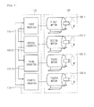
- Fig. 5 is a schematic view illustrating a configuration of an inverter according to an embodiment.
- Figs. 6 and 7 are flowcharts illustrating a communication method of an inverter communication system according to an embodiment.
- Fig. 2 is a schematic view illustrating a configuration of an inverter communication system according to an embodiment.
- the inverter communication system includes an inverter 110, and a motor 120 operated by a control of the inverter 110.
- the inverter 110 includes a first inverter 110-1, a second inverter 110-2, a third inverter 110-3, and a fourth inverter 110-4.
- the motor 120 includes a first motor 120-1 operated by a control of the first inverter 110-1, a second motor 120-2 operated by a control of the second inverter 110-2, a third motor 120-3 operated by a control of the third inverter 110-3, and a fourth motor 120-4 operated by a control of the fourth inverter 110-4.
- the first inverter 110-1, the second inverter 110-2, the third inverter 110-3, and the fourth inverter 110-4 are mutually connected to each other through a communication lines.
- the first inverter 110-1 is connected to the second inverter 110-2; the second inverter 110-2 is connected to the third inverter 110-3; the third inverter 110-3 is connected to the fourth inverter 110-4; and the fourth inverter 110-4 is connected to the first inverter 110-1, on the basis of the transmission line.
- the first inverter 110-1 transmits a data frame to the second inverter 110-2; the second inverter 110-2 transmits a data frame to the third inverter 110-3; the third inverter 110-3 transmits a data frame to the fourth inverter 110-4; and the fourth inverter 110-4 transmits a data frame to the first inverter 110-1.
- the transmitted data frame may be a data frame generated from an inverter itself (i.e., a transfer subject), or unlike that, may be a data frame generated from another and transmitted through an adjacent inverter.
- the first inverter 110-1, the second inverter 110-2, the third inverter 110-3, and the fourth inverter 110-4 that constitute the inverter system may perform mutual data communication through the communication line.
- each of the first inverter 110-1, the second inverter 110-2, the third inverter 110-3, and the fourth inverter 110-4 may operate as a master to perform communication.
- the first inverter 110-1 may operate as a master; the second inverter 110-2 may operate as a master; the third inverter 110-3 may operate as a master; and the fourth inverter 110-4 may operate as a master.
- the transmitted data frame includes inverter information corresponding to a final destination where the data frame arrives finally and inverter information corresponding to a departure where the data frame is transmitted initially
- the data frame may continuously remain on a communication line between the plurality of inverters.
- the data frame needs to include departure information corresponding to an inverter that generates the data frame and initially transmits the generated data frame.
- first, original identifiers are assigned to the first inverter 110-1, the second inverter 110-2, the third inverter 110-3, and the fourth inverter 110-4, respectively.
- Fig. 3 is a view illustrating an original identifier assigned to an inverter constituting an inverter system according to an embodiment.
- the first inverter 110-1 has the original identifier of '0x01'; the second inverter 110-1 has the original identifier of '0x02'; the third inverter 110-3 has the original identifier of '0x03'; and the fourth inverter 110-4 has the original identifier of '0x04.;
- the original identifiers are information to distinguish and identify each inverter, and the data frame includes information corresponding to the original identifier assigned to each of the inverters.
- the data frame includes destination information that refers to an original identifier of an inverter corresponding to a final destination and departure information that refers to an original identifier corresponding to an initial departure.
- each of the inverters generates the data frame if a data frame to be transmitted is needed, and inserts departure information including an original identifier assigned to itself into the generated data frame.
- each of the inverters inserts destination information including an original identifier of an inverter corresponding to a final destination where the generated data frame arrives into the data frame.
- Fig. 4 is a schematic view illustrating a format of a data frame according to an embodiment.
- the data frame 200 includes fields such as destination information 210, departure information 220, a Frame Type 230, a Data Length 240, Data 250 and a CRC16 260.
- the destination information 210 includes an original identifier of an inverter corresponding to a final destination of the data frame 200.
- the field of the destination information 210 may consist of 2 bits. For example, if the data frame 200 to be transmitted from the first inverter 110-1 to the fourth inverter 110-4 is generated, the field of the destination information 210 includes the original identifier of '0x04' assigned to the fourth inverter 110-4.
- the destination information 210 is used to stably transmit the data frame 200 to a specific inverter corresponding to a final destination.
- the departure information 220 includes an original identifier of an inverter (i.e., a departure of the data frame 200) that generates the data frame 200.
- the field of the departure information 220 may consist of 2 bits. For example, if the data frame 200 to be transmitted from the second inverter 110-2 to the third inverter 110-3 is generated, the field of the departure information 220 includes the original identifier of '0x02' assigned to the second inverter 110-2.
- the departure information 220 may prevent the data frame 220 from continuously remaining on a communication line due to communication errors.
- the Frame Type 230 includes information on kinds of data in the data frame 200.
- the Data Length 240 includes information on the length of the data frame 200.
- the Data 250 includes data that are actually delivered to a specific inverter.
- the data in the field of the Data 250 may include basic information data including at least one of a driving direction, a driving status, and trip of an inverter, and command data including at least one of DC-link voltage, output voltage, output current, output frequency, and output power of an inverter.
- the CRC16 260 includes information used for checking errors in the data frame 200.
- the data frame 200 is stably transmitted to an inverter corresponding to a final destination.
- the departure information 220 is added to the data frame 200, the situation that the data frame 200 continuously remains on a communication line between the inverters due to communication errors may be prevented in advance.
- Fig. 5 is a schematic view illustrating a configuration of an inverter according to an embodiment.
- the inverter 110 includes a data transmission unit 111, a data reception unit 112, a storage unit 113, a data frame generation unit 114, and a control unit 115.
- Fig. 5 may illustrate a configuration of one inverter among the first inverter 110-1, the second inverter 110-2, the third inverter 110-3, and the fourth inverter 110-4.
- the data transmission unit 111 transmits a data frame to another adjacent inverter.
- the data transmission unit 111 transmits a data frame to an adjacent inverter connected to a communication line, i.e., the subsequent inverter having the subsequent original identifier assigned based on a current inverter having its own original identifier.
- the data frame transmitted through the data transmission unit 111 may be a data frame generated from the data frame generation unit 114, or may be a data frame transmitted from a previous inverter having a previous original identifier assigned into a current inverter having its own original identifier.
- the data transmission unit 112 receives a data frame transmitted from another adjacent inverter.
- the storage unit 113 stores various programs and information necessary for driving the inverter 110. Especially, the storage unit 113 stores an original identifier assigned to its inverter.
- the data frame generation unit 114 generates a data frame that is to be transmitted to an adjacent inverter.
- the data frame generation unit 114 generates a data frame having the same format as Fig. 4 .
- the departure information of the generated data frame includes its own original identifier. Since the departure information corresponds to the information on the departure of the data frame, that is, the original identifier of an inverter that generates the data frame, the data frame generation unit 114 constitutes the departure information by using the original identifier assigned to its own inverter.
- the control unit 115 controls general operations of the inverter 110.
- control unit 115 controls an operation of a motor, in case that data need to be transmitted to another inverter, a data frame to be transmitted to the other inverter is generated from the data frame generation unit 114.
- control unit 15 confirms the original identifier of an inverter to which the data frame is transmitted. Accordingly, the control unit 15 creates destination information of the data frame on the basis of the confirmed original identifier, and creates departure information of the data frame on the basis of the original identifier of its own inverter.
- control unit 115 confirms the destination information in the data frame.
- control unit 115 confirms whether an original identifier in the received destination information of the data frame is that assigned to its own inverter. Accordingly, the control unit 115 applies data in the data field of the data frame when the original identifier in the received destination information of the data frame is identical to that assigned to its own inverter.
- control unit 115 transmits the received data frame to an adjacent inverter when the original identifier in the received destination information of the data frame is different from that assigned to its own inverter.
- the inverter serves to relay the transmission of the data frame.
- control unit 115 confirms departure information in the data frame before transmitting the received data frame to adjacent another inverter, and accordingly, confirms whether the departure information corresponds to the original identifier assigned to its own inverter.
- control unit 115 confirms whether the received data frame is a data frame generated through the its own inverter.
- control unit 115 determines that the data frame remains on a communication line due to communication errors when the received data frame corresponds to a data frame generated through its own inverter, and accordingly, deletes the received data frame without transmitting it to another inverter.
- control unit 115 transmits the data frame to adjacent another inverter when departure information in the received data frame is different from an original identifier in its own inverter.
- the inverter 110 transmits the received data frame to adjacent another inverter by using departure information and destination information in a data frame.
- the inverter 110 generates a data frame including destination information having an original identifier of an inverter to which the data is to be transmitted, and transmits the data frame to adjacent another inverter.
- the inverter implements a communication system with adjacent another inverter through a communication line in a ring form
- an efficient communication system may be implemented at low cost in an inverter linking system, and all inverters may operate as a master.
- the system configuration becomes easier.
- Figs. 6 and 7 are flowcharts illustrating a communication method of an inverter communication system according to an embodiment.
- Fig. 6 is the flowchart illustrating operations when data that are to be transmitted from its own inverter into another specific inverter occur.
- Fig. 7 is the flowchart illustrating operations when a data frame is transmitted from another inverter into its own inverter.
- Fig. 6 will be described on the assumption that operations are performed in the first inverter 110-1. However, the operations of Fig. 6 may be performed in any one of the second inverter 110-2, the third inverter 110-3, and the fourth inverter 110-4, not in the first inverter 110-1.
- the first inverter 110-1 confirms whether transmission data to be transmitted to another inverter occurs during an operation control of the first motor 120-1 in operation S110.
- the first inverter 110-1 confirms whether an event for transmitting information data including at least one of a driving direction, a driving status, and trip of an inverter, which is to be transmitted to another inverter, or command data including at least one of DC-link voltage, output voltage, output current, output frequency, and output power of an inverter occurs.
- the first inverter 110-1 confirms the original identifier of an inverter to which the transmission data are transmitted. For example, if transmission data to be transmitted from the first inverter 110-1 to the third inverter 110-3 occur, the first inverter 110-1 confirms the original identifier assigned to the third inverter 110-3 in operation S120.
- the original identifier is stored in the storage unit 113 of the inverter 110.
- the first inverter 110-1 confirms the original identifier of an inverter to which the transmission data are transmitted, and creates destination information by using the confirmed original identifier.
- the first inverter 110-1 creates departure information by using an original identifier assigned to its own inverter, and generates a data frame including the destination information and the departure information in operation S130.
- the first inverter 110-1 generates a data frame, which includes departure information that has an original identifier of '0x01' assigned to itself, destination information that has an original identifier of '0x03' assigned to the third inverter 110-3, and data that are to be transmitted to the third inverter 110-3.
- the first inverter 110-1 transmits the generated data frame to adjacent another inverter connected to a communication line in operation S140.
- the first inverter 110-1 transmits the generated data frame to the second inverter 110-2 connected through the communication line.
- Fig. 7 will be described on the assumption that operations are performed in the second inverter 110-2. However, it is apparent that the operations may be performed in the first, third, and fourth inverters.
- the second inverter 110-2 confirms whether a data frame is received through an adjacent inverter in operation S210.
- control unit 115 of the second inverter 110-2 confirms whether the data frame is received through the data reception unit 112. That is, the second inverter 110-2 confirms whether the data frame is received through the first inverter 110-1.
- the second inverter 110-2 confirms the destination information in the received data frame in operation S220.
- the second inverter 110-2 confirms the original identifier of an inverter corresponding to the final destination of the data frame by using the destination information in the data frame.
- the second inverter 110-2 determines whether the confirmed original identifier of the inverter corresponding to the final destination is identical to its own identifier in operation S230.
- the second inverter 110-2 analyzes the received data frame in operation S240. That is, the second inverter 110-2 analyzes a data field in the data frame when the final destination of the received data frame is its own inverter.
- the second inverter 110-2 applies data in the analyzed data field in order to drive the second motor 120-2 in operation S250.
- the second inverter 110-2 confirms the departure information in the received data frame in operation S260.
- the second inverter 110-2 confirms the original identifier of an inverter that initially transmits the received data frame, that is, the original identifier of an inverter that generates the data frame.
- the second inverter 110-2 determines whether the confirmed original identifier is identical to its own original identifier in operation S270. That is, the second inverter 110-2 determines whether the received data frame is a data frame generated by the second inverter itself 110-2.
- the second inverter 110-2 deletes the received data frame in operation S280.
- the second inverter 110-2 determines that the data frame remains on a communication line due to communication errors, and accordingly, deletes the received data frame.
- the second inverter 110-2 transmits the received data frame to adjacent another inverter, that is, the third inverter 110-3.
- the third inverter 110-3 performs operations S210 to S290 of Fig. 7 .
- an efficient communication system may be implemented at low cost in an inverter linking system, and all inverters may operate as a master.
- the system configuration becomes easier.
Abstract
Description
- The present application claims priority under 35 U.S.C. 119 and 35 U.S.C. 365 to Korean Patent Application No.
10-2011-0055336 (filed on June 8, 2011 - The present disclosure relates to an inverter, and more particularly, to a communication method in an inverter system including a plurality of inverts.
- In modern industries, most of driving devices include motors, and inverters are required to precisely control the motors. Additionally, a Programmable Logic Controller (PLC) is currently used as a method of controlling a plurality of inverters.
- Moreover, motors are indispensable across all industries, and therefore, the need for inverters is increased. As devices for efficiently controlling motors, inverters reduce power consumption of motors and increase their energy efficiency.
- Recently, linking and operating a plurality of motors become more frequent, and accordingly, a linking operation by sharing information on a plurality of inverters becomes more frequent.
- As mentioned above, when inverters are in linking operations, a plurality of inverters need to exchange information data or command data with each other in order to smoothly drive motors.
-
Fig. 1 is a schematic view illustrating a configuration of a related art inverter system. - Referring to
Fig. 1 , an inverter communication system includes acommunication device 10, a plurality of inverters 20-1, 20-2, 20-3, and 20-4, and a plurality of motors 30-1, 30-2, 30-3, and 30-4 driven by controls of the inverters 20-1, 20-2, 20-3, and 20-4. - The
communication device 10 operates as a communication master for communication between the plurality of inverters 20-1, 20-2, 20-3, and 20-4. - The plurality of inverters 20-1, 20-2, 20-3, and 20-4 serve as a slave device to perform a communication with the
communication device 10 through a communication line. Additionally, the plurality of inverters 20-1, 20-2, 20-3, and 20-4 and thecommunication device 10 exchange mutual data with each other through the communication line. - The
communication device 10 collects data through communication with each of the plurality of inverters 20-1, 20-2, 20-3, and 20-4, and controls each of the plurality of inverters 20-1, 20-2, 20-3, and 20-4 by using the collected data. - In the same manner, the
communication device 10 may efficiently control the plurality of inverters 20-1, 20-2, 20-3, and 20-4 in a complex system or a large scale system. - However, if there are a plurality of motors 30-1, 30-2, 30-3, and 30-4 (for example, two to five motors), the structure of the inverter system becomes complex. Accordingly, operators may make errors easily.
- Additionally, since the inverter system includes the
additional communication device 10, system building costs are increased. - Additionally, since the
communication device 10 needs to be installed in a different place than a place where the plurality of inverters 20-1, 20-2, 20-3, and 20-4 are installed, installation space may be wasted. - Moreover, since the inverters 20-1, 20-2, 20-3, and 20-4 communicate with the
communication device 10 that operates as the master, a communication line used for communicating with thecommunication device 10 becomes longer. Therefore, errors may occur in communication data according to external environmental conditions such as noise. - Embodiments provide an efficient communication method in a system including a plurality of inverters.
- Embodiments also provide a communication method in which one of a plurality of inverters operates as a master to communicate with another inverter.
- In one embodiment, an inverter communication system includes: a plurality of inverters connected to each other through a communication line, and assigned with different original identifiers for mutual distinction, wherein each of the plurality of inverters: receives a data frame transmitted through a previous inverter; selectively transmits the received data frame to a subsequent inverter; generates a data frame to be transmitted when data to be transmitted to a specific inverter occur; and transmits the generated data frame to a subsequent inverter.
- In another embodiment, an inverter includes: a data reception unit receiving a data frame transmitted through a previous inverter; a data transmission unit selectively transmitting the data frame received through the data reception unit to a subsequent inverter; and a control unit confirming destination information in the data frame when the data frame is received, and selectively transmitting the data frame to a subsequent inverter by using the confirmed destination information,
- The details of one or more embodiments are set forth in the accompanying drawings and the description below. Other features will be apparent from the description and drawings, and from the claims.
-
Fig. 1 is a schematic view illustrating a configuration of a related art inverter communication system. -
Fig. 2 is a schematic view illustrating a configuration of an inverter communication system according to an embodiment. -
Fig. 3 is a view illustrating an original identifier assigned to each inverter according to an embodiment. -
Fig. 4 is a schematic view illustrating a format of a data frame according to an embodiment. -
Fig. 5 is a schematic view illustrating a configuration of an inverter according to an embodiment. -
Figs. 6 and7 are flowcharts illustrating a communication method of an inverter communication system according to an embodiment. - Reference will now be made in detail to the embodiments of the present disclosure, examples of which are illustrated in the accompanying drawings.
- Suggested embodiments will be described.
-
Fig. 2 is a schematic view illustrating a configuration of an inverter communication system according to an embodiment. - Referring to
Fig. 2 , the inverter communication system includes aninverter 110, and amotor 120 operated by a control of theinverter 110. - The
inverter 110 includes a first inverter 110-1, a second inverter 110-2, a third inverter 110-3, and a fourth inverter 110-4. - Additionally, the
motor 120 includes a first motor 120-1 operated by a control of the first inverter 110-1, a second motor 120-2 operated by a control of the second inverter 110-2, a third motor 120-3 operated by a control of the third inverter 110-3, and a fourth motor 120-4 operated by a control of the fourth inverter 110-4. - The first inverter 110-1, the second inverter 110-2, the third inverter 110-3, and the fourth inverter 110-4 are mutually connected to each other through a communication lines.
- That is, the first inverter 110-1 is connected to the second inverter 110-2; the second inverter 110-2 is connected to the third inverter 110-3; the third inverter 110-3 is connected to the fourth inverter 110-4; and the fourth inverter 110-4 is connected to the first inverter 110-1, on the basis of the transmission line.
- Accordingly, the first inverter 110-1 transmits a data frame to the second inverter 110-2; the second inverter 110-2 transmits a data frame to the third inverter 110-3; the third inverter 110-3 transmits a data frame to the fourth inverter 110-4; and the fourth inverter 110-4 transmits a data frame to the first inverter 110-1.
- At this point, the transmitted data frame may be a data frame generated from an inverter itself (i.e., a transfer subject), or unlike that, may be a data frame generated from another and transmitted through an adjacent inverter.
- Accordingly, the first inverter 110-1, the second inverter 110-2, the third inverter 110-3, and the fourth inverter 110-4 that constitute the inverter system may perform mutual data communication through the communication line.
- Additionally, according to data communication environments, each of the first inverter 110-1, the second inverter 110-2, the third inverter 110-3, and the fourth inverter 110-4 may operate as a master to perform communication.
- That is, according to data communication environments, the first inverter 110-1 may operate as a master; the second inverter 110-2 may operate as a master; the third inverter 110-3 may operate as a master; and the fourth inverter 110-4 may operate as a master.
- At this point, the transmitted data frame includes inverter information corresponding to a final destination where the data frame arrives finally and inverter information corresponding to a departure where the data frame is transmitted initially
- That is, when the data frame is simply transmitted between a plurality of inverters, information that the data frame is transmitted to which one of the plurality of inverters (i.e., destination information) needs to be included in the data frame.
- Additionally, even if the data frame includes destination information, due to transmission errors, the data frame may continuously remain on a communication line between the plurality of inverters.
- That is, if destination information in the transmitted data frame is damaged or the data frame itself is damaged, since there is no final destination of the data frame, the data frame remains between the plurality of inverters.
- Accordingly, the data frame needs to include departure information corresponding to an inverter that generates the data frame and initially transmits the generated data frame.
- For this, first, original identifiers are assigned to the first inverter 110-1, the second inverter 110-2, the third inverter 110-3, and the fourth inverter 110-4, respectively.
-
Fig. 3 is a view illustrating an original identifier assigned to an inverter constituting an inverter system according to an embodiment. - Referring to
Fig. 3 , different original identifiers are assigned to the first inverter 110-1, the second inverter 110-2, the third inverter 110-3, and the fourth inverter 110-4, respectively, all of which constitute the inverter system. - That is, the first inverter 110-1 has the original identifier of '0x01'; the second inverter 110-1 has the original identifier of '0x02'; the third inverter 110-3 has the original identifier of '0x03'; and the fourth inverter 110-4 has the original identifier of '0x04.;
- The original identifiers are information to distinguish and identify each inverter, and the data frame includes information corresponding to the original identifier assigned to each of the inverters.
- That is, the data frame includes destination information that refers to an original identifier of an inverter corresponding to a final destination and departure information that refers to an original identifier corresponding to an initial departure.
- That is, each of the inverters generates the data frame if a data frame to be transmitted is needed, and inserts departure information including an original identifier assigned to itself into the generated data frame.
- Moreover, each of the inverters inserts destination information including an original identifier of an inverter corresponding to a final destination where the generated data frame arrives into the data frame.
-
Fig. 4 is a schematic view illustrating a format of a data frame according to an embodiment. - Referring to
Fig. 4 , the data frame 200includes fields such asdestination information 210,departure information 220, aFrame Type 230, aData Length 240,Data 250 and aCRC16 260. - The
destination information 210 includes an original identifier of an inverter corresponding to a final destination of thedata frame 200. At this point, the field of thedestination information 210 may consist of 2 bits. For example, if thedata frame 200 to be transmitted from the first inverter 110-1 to the fourth inverter 110-4 is generated, the field of thedestination information 210 includes the original identifier of '0x04' assigned to the fourth inverter 110-4. - The
destination information 210 is used to stably transmit thedata frame 200 to a specific inverter corresponding to a final destination. - The
departure information 220 includes an original identifier of an inverter (i.e., a departure of the data frame 200) that generates thedata frame 200. At this point, the field of thedeparture information 220 may consist of 2 bits. For example, if thedata frame 200 to be transmitted from the second inverter 110-2 to the third inverter 110-3 is generated, the field of thedeparture information 220 includes the original identifier of '0x02' assigned to the second inverter 110-2. - The
departure information 220 may prevent thedata frame 220 from continuously remaining on a communication line due to communication errors. - The
Frame Type 230 includes information on kinds of data in thedata frame 200. - The
Data Length 240 includes information on the length of thedata frame 200. - The
Data 250 includes data that are actually delivered to a specific inverter. - The data in the field of the
Data 250 may include basic information data including at least one of a driving direction, a driving status, and trip of an inverter, and command data including at least one of DC-link voltage, output voltage, output current, output frequency, and output power of an inverter. - The
CRC16 260 includes information used for checking errors in thedata frame 200. - As mentioned above, according to an embodiment, since the
destination information 210 is added to thedata frame 200, thedata frame 200 is stably transmitted to an inverter corresponding to a final destination. - Additionally, since the
departure information 220 is added to thedata frame 200, the situation that thedata frame 200 continuously remains on a communication line between the inverters due to communication errors may be prevented in advance. - Hereinafter, an inverter constituting the above inverter system and a communication process of the inverter will be described in more detail.
-
Fig. 5 is a schematic view illustrating a configuration of an inverter according to an embodiment. - Referring to
Fig. 5 , theinverter 110 includes adata transmission unit 111, adata reception unit 112, astorage unit 113, a dataframe generation unit 114, and acontrol unit 115. -
Fig. 5 may illustrate a configuration of one inverter among the first inverter 110-1, the second inverter 110-2, the third inverter 110-3, and the fourth inverter 110-4. - The
data transmission unit 111 transmits a data frame to another adjacent inverter. - That is, the
data transmission unit 111 transmits a data frame to an adjacent inverter connected to a communication line, i.e., the subsequent inverter having the subsequent original identifier assigned based on a current inverter having its own original identifier. - At this point, the data frame transmitted through the
data transmission unit 111 may be a data frame generated from the dataframe generation unit 114, or may be a data frame transmitted from a previous inverter having a previous original identifier assigned into a current inverter having its own original identifier. - The
data transmission unit 112 receives a data frame transmitted from another adjacent inverter. - The
storage unit 113 stores various programs and information necessary for driving theinverter 110. Especially, thestorage unit 113 stores an original identifier assigned to its inverter. - The data
frame generation unit 114 generates a data frame that is to be transmitted to an adjacent inverter. - That is, the data
frame generation unit 114 generates a data frame having the same format asFig. 4 . At this point, the departure information of the generated data frame includes its own original identifier. Since the departure information corresponds to the information on the departure of the data frame, that is, the original identifier of an inverter that generates the data frame, the dataframe generation unit 114 constitutes the departure information by using the original identifier assigned to its own inverter. - The
control unit 115 controls general operations of theinverter 110. - Especially, while the
control unit 115 controls an operation of a motor, in case that data need to be transmitted to another inverter, a data frame to be transmitted to the other inverter is generated from the dataframe generation unit 114. - At this point, the control unit 15 confirms the original identifier of an inverter to which the data frame is transmitted. Accordingly, the control unit 15 creates destination information of the data frame on the basis of the confirmed original identifier, and creates departure information of the data frame on the basis of the original identifier of its own inverter.
- Additionally, on receiving the data frame transmitted through the
data reception unit 112, thecontrol unit 115 confirms the destination information in the data frame. - That is, the
control unit 115 confirms whether an original identifier in the received destination information of the data frame is that assigned to its own inverter. Accordingly, thecontrol unit 115 applies data in the data field of the data frame when the original identifier in the received destination information of the data frame is identical to that assigned to its own inverter. - Moreover, the
control unit 115 transmits the received data frame to an adjacent inverter when the original identifier in the received destination information of the data frame is different from that assigned to its own inverter. At this point, the inverter serves to relay the transmission of the data frame. - At this point, the
control unit 115 confirms departure information in the data frame before transmitting the received data frame to adjacent another inverter, and accordingly, confirms whether the departure information corresponds to the original identifier assigned to its own inverter. - That is, the
control unit 115 confirms whether the received data frame is a data frame generated through the its own inverter. - Moreover, the
control unit 115 determines that the data frame remains on a communication line due to communication errors when the received data frame corresponds to a data frame generated through its own inverter, and accordingly, deletes the received data frame without transmitting it to another inverter. - That is, the
control unit 115 transmits the data frame to adjacent another inverter when departure information in the received data frame is different from an original identifier in its own inverter. - As mentioned above, the
inverter 110 transmits the received data frame to adjacent another inverter by using departure information and destination information in a data frame. - Furthermore, once data to be transmitted to another inverter occur, the
inverter 110 generates a data frame including destination information having an original identifier of an inverter to which the data is to be transmitted, and transmits the data frame to adjacent another inverter. - Since the inverter implements a communication system with adjacent another inverter through a communication line in a ring form, an efficient communication system may be implemented at low cost in an inverter linking system, and all inverters may operate as a master. The system configuration becomes easier.
-
Figs. 6 and7 are flowcharts illustrating a communication method of an inverter communication system according to an embodiment. -
Fig. 6 is the flowchart illustrating operations when data that are to be transmitted from its own inverter into another specific inverter occur.Fig. 7 is the flowchart illustrating operations when a data frame is transmitted from another inverter into its own inverter. - Hereinafter,
Fig. 6 will be described on the assumption that operations are performed in the first inverter 110-1. However, the operations ofFig. 6 may be performed in any one of the second inverter 110-2, the third inverter 110-3, and the fourth inverter 110-4, not in the first inverter 110-1. - Referring to
Fig. 6 , first, the first inverter 110-1 confirms whether transmission data to be transmitted to another inverter occurs during an operation control of the first motor 120-1 in operation S110. - That is, the first inverter 110-1 confirms whether an event for transmitting information data including at least one of a driving direction, a driving status, and trip of an inverter, which is to be transmitted to another inverter, or command data including at least one of DC-link voltage, output voltage, output current, output frequency, and output power of an inverter occurs.
- On the basis of the determination result in operation S110, if transmission data to be transmitted to another inverter occurs, the first inverter 110-1 confirms the original identifier of an inverter to which the transmission data are transmitted. For example, if transmission data to be transmitted from the first inverter 110-1 to the third inverter 110-3 occur, the first inverter 110-1 confirms the original identifier assigned to the third inverter 110-3 in operation S120.
- The original identifier is stored in the
storage unit 113 of theinverter 110. - The first inverter 110-1 confirms the original identifier of an inverter to which the transmission data are transmitted, and creates destination information by using the confirmed original identifier.
- Additionally, the first inverter 110-1 creates departure information by using an original identifier assigned to its own inverter, and generates a data frame including the destination information and the departure information in operation S130.
- That is, the first inverter 110-1 generates a data frame, which includes departure information that has an original identifier of '0x01' assigned to itself, destination information that has an original identifier of '0x03' assigned to the third inverter 110-3, and data that are to be transmitted to the third inverter 110-3.
- Then, the first inverter 110-1 transmits the generated data frame to adjacent another inverter connected to a communication line in operation S140.
- That is, the first inverter 110-1 transmits the generated data frame to the second inverter 110-2 connected through the communication line.
- Hereinafter, a communication process of the above transmitted data frame will be described.
- Hereinafter,
Fig. 7 will be described on the assumption that operations are performed in the second inverter 110-2. However, it is apparent that the operations may be performed in the first, third, and fourth inverters. - Referring to
Fig. 7 , the second inverter 110-2 confirms whether a data frame is received through an adjacent inverter in operation S210. - That is, the
control unit 115 of the second inverter 110-2 confirms whether the data frame is received through thedata reception unit 112. That is, the second inverter 110-2 confirms whether the data frame is received through the first inverter 110-1. - On the basis of the determination result in operation S210, if the data frame is received in the second inverter 110-2, the second inverter 110-2 confirms the destination information in the received data frame in operation S220.
- That is, the second inverter 110-2 confirms the original identifier of an inverter corresponding to the final destination of the data frame by using the destination information in the data frame.
- Then, the second inverter 110-2 determines whether the confirmed original identifier of the inverter corresponding to the final destination is identical to its own identifier in operation S230.
- On the basis of the determination result in operation S230, if the confirmed original identifier of the inverter corresponding to the final destination is identical to its own identifier, the second inverter 110-2 analyzes the received data frame in operation S240. That is, the second inverter 110-2 analyzes a data field in the data frame when the final destination of the received data frame is its own inverter.
- Moreover, the second inverter 110-2 applies data in the analyzed data field in order to drive the second motor 120-2 in operation S250.
- Moreover, on the basis of the determination result in operation S230, if the confirmed original identifier of the inverter corresponding to the final destination is not identical to its own identifier, the second inverter 110-2 confirms the departure information in the received data frame in operation S260.
- That is, the second inverter 110-2 confirms the original identifier of an inverter that initially transmits the received data frame, that is, the original identifier of an inverter that generates the data frame.
- When the original identifier of an inverter that initially transmits the data frame is confirmed, the second inverter 110-2 determines whether the confirmed original identifier is identical to its own original identifier in operation S270. That is, the second inverter 110-2 determines whether the received data frame is a data frame generated by the second inverter itself 110-2.
- When the received data frame is generated by the second inverter 110-2 itself, the second inverter 110-2 deletes the received data frame in operation S280.
- That is, if the received data frame is generated by the second inverter 110-2 itself, the second inverter 110-2 determines that the data frame remains on a communication line due to communication errors, and accordingly, deletes the received data frame.
- Additionally, if the received data frame is not generated by the second inverter 110-2 itself, the second inverter 110-2 transmits the received data frame to adjacent another inverter, that is, the third inverter 110-3.
- Then, when the data frame is transmitted from the second inverter 110-2 to the third inverter 110-3, the third inverter 110-3 performs operations S210 to S290 of
Fig. 7 . - According to embodiments, an efficient communication system may be implemented at low cost in an inverter linking system, and all inverters may operate as a master. The system configuration becomes easier.
- Although embodiments have been described with reference to a number of illustrative embodiments thereof, it should be understood that numerous other modifications and embodiments can be devised by those skilled in the art that will fall within the spirit and scope of the principles of this disclosure. More particularly, various variations and modifications are possible in the component parts and/or arrangements of the subject combination arrangement within the scope of the disclosure, the drawings and the appended claims. In addition to variations and modifications in the component parts and/or arrangements, alternative uses will also be apparent to those skilled in the art.
Claims (15)
- An inverter communication system assigned with different original identifiers and performing a linking operation by sharing information through a communication line, wherein each of the plurality of inverters:receives a data frame transmitted through a previous inverter;selectively transmits the received data frame to a subsequent inverter;generates a data frame to be transmitted when data to be transmitted to a specific inverter occur; andtransmits the generated data frame to a subsequent inverter.
- The inverter communication system according to claim 1, wherein each of the plurality of inverters controls a motor by applying data in the data frame when the destination information in the received data frame is identical to an original identifier assigned to the each; and
transmits the received data frame to a subsequent inverter if the destination information is different from the original identifier assigned to the each. - The inverter communication system according to any one of claims 1 and 2, wherein the data frame comprises departure information having an original identifier of an inverter that initially transmits the data frame.
- The inverter communication system according to claim 3, wherein each of the plurality of inverters operates as a master to generate a data frame to be transmitted when data to be transmitted to the specific inverter occur and transmits the generated data frame to a subsequent inverter,
wherein the generated data frame comprises destination information having an original identifier of an inverter where the data frame arrives and departure information having an original identifier of an inverter where the data frame departures. - The inverter communication system according to claim 4, wherein each of the plurality of inverter deletes the received data frame when the departure information in the received data frame is identical to an original identifier assigned to the each; and transmits the received data frame to a subsequent inverter when the departure information is different from the original identifier assigned to the each.
- An inverter comprises:a data reception unit receiving a data frame transmitted through a previous inverter;a data transmission unit selectively transmitting the data frame received through the data reception unit to a subsequent inverter; anda control unit confirming destination information in the data frame when the data frame is received, and selectively transmitting the data frame to a subsequent inverter by using the confirmed destination information,wherein the destination information is an original identifier of an inverter where the data frame arrives finally; andthe control unit drives a motor by applying the received data frame when the destination information is identical to an original identifier assigned to itself and transmits the received data frame to a subsequent inverter when the destination information is different from the original identifier assigned to itself.
- The inverter according to claim 6, further comprising a data frame generation unit generating a data frame to be transmitted to a specific inverter when data to be transmitted to the specific inverter occur,
wherein destination information having an original identifier of an inverter where the generated data frame arrives finally is inserted into the generated data frame. - The inverter according to claim 7, wherein the generated data frame comprises an original identifier of an inverter that generates the data frame.
- The inverter according to claim 8, wherein the control unit confirms departure information of the received data frame when the destination information of the received data frame is different from an original identifier assigned to itself;
deletes the received data frame when the confirmed departure information is identical to the original identifier assigned to itself; and
transmitting the received data frame to a subsequent inverter when the confirmed departure information is different from the original identifier assigned to itself. - A communication method of an inverter comprising:receiving a data frame transmitted through a previous inverter;confirming destination information in the received data frame;determining whether the confirmed destination information is identical to an original identifier assigned to itself;driving a motor by applying the received data frame when the destination information is identical to the original identifier assigned to itself; andtransmitting the received data frame to a subsequent inverter when the destination information is different from the original identifier assigned to itself.
- The method according to claim 10, further comprising:generating a data frame to be transmitted to a specific inverter when data to be transmitted to the specific inverter occur; andinserting destination information having an original identifier of an inverter where the generated data frame arrives finally into the generated data frame.
- The method according to claim 11, wherein the generating of the data frame comprises generating a data frame having departure information with an original identifier of an inverter that generates the data frame.
- The method according to claim 12, wherein the data frame received through the previous inverter is a data frame generated by itself or a data frame generated by another inverter.
- The method according to claim 13, further comprising;
confirming departure information in the received data frame when the confirmed destination information is different from an original identifier assigned to itself,
Wherein the transmitting of the data frame to the subsequent inverter is performed when the confirmed departure information is different from the original identifier assigned to itself. - The method according to claim 14, when the confirmed departure information is the identical to the original identifier assigned to itself, further comprising deleting the received data frame.
Applications Claiming Priority (1)
| Application Number | Priority Date | Filing Date | Title |
|---|---|---|---|
| KR1020110055336A KR101779614B1 (en) | 2011-06-08 | 2011-06-08 | Inverter communication system |
Publications (3)
| Publication Number | Publication Date |
|---|---|
| EP2533400A2 true EP2533400A2 (en) | 2012-12-12 |
| EP2533400A3 EP2533400A3 (en) | 2017-12-13 |
| EP2533400B1 EP2533400B1 (en) | 2019-11-20 |
Family
ID=46458149
Family Applications (1)
| Application Number | Title | Priority Date | Filing Date |
|---|---|---|---|
| EP12170451.4A Active EP2533400B1 (en) | 2011-06-08 | 2012-06-01 | Inverter, inverter communication system, communication method thereof |
Country Status (5)
| Country | Link |
|---|---|
| US (1) | US9071086B2 (en) |
| EP (1) | EP2533400B1 (en) |
| KR (1) | KR101779614B1 (en) |
| CN (1) | CN102820948B (en) |
| ES (1) | ES2769584T3 (en) |
Cited By (1)
| Publication number | Priority date | Publication date | Assignee | Title |
|---|---|---|---|---|
| WO2016165718A1 (en) * | 2015-04-16 | 2016-10-20 | Vestas Wind Systems A/S | Controlling of wind-turbine-converter system over a communication bus |
Families Citing this family (3)
| Publication number | Priority date | Publication date | Assignee | Title |
|---|---|---|---|---|
| CN103957034B (en) * | 2014-05-16 | 2015-12-09 | 浙江昱能科技有限公司 | The power line communication method of inverter system |
| CN108712784B (en) * | 2018-05-11 | 2020-07-24 | 成都六零加信息技术有限公司 | Communication method and device |
| WO2020059037A1 (en) * | 2018-09-19 | 2020-03-26 | 株式会社安川電機 | Power conversion system, ip address transmission method for power conversion device and program |
Family Cites Families (19)
| Publication number | Priority date | Publication date | Assignee | Title |
|---|---|---|---|---|
| CN1031775C (en) * | 1993-07-23 | 1996-05-08 | 武法正 | Digital user loop central machine system |
| JP2000047715A (en) | 1998-07-29 | 2000-02-18 | Omron Corp | Communication device |
| JP3784989B2 (en) | 1999-03-31 | 2006-06-14 | 株式会社東芝 | Electric motor control communication system |
| JP2005537556A (en) * | 2002-08-29 | 2005-12-08 | コーニンクレッカ フィリップス エレクトロニクス エヌ ヴィ | Reconfigurable electronic device having interconnected data storage devices |
| EP1414176B1 (en) * | 2002-10-24 | 2010-03-31 | Panasonic Corporation | Communication device and communication method immune to burst error, program for executing the method, and computer-readable storage medium storing the program |
| BR0300173A (en) * | 2003-01-31 | 2004-10-26 | Engetron Engenharia Eletronica | Single-phase or multi-phase inverter power supply system |
| CA2518696C (en) * | 2003-07-30 | 2012-11-13 | Nippon Telegraph And Telephone Corporation | Wireless packet communication method |
| DE102005014783A1 (en) * | 2005-03-31 | 2006-10-05 | Siemens Ag | Method and devices for transmitting data to a data line between a control device and at least one decentralized data processing device |
| US8432809B2 (en) * | 2005-04-27 | 2013-04-30 | Broadcom Corporation | Method for communication between processors |
| DE102006003904A1 (en) * | 2006-01-27 | 2007-08-09 | Sma Technologie Ag | Method for converting a DC voltage into a three-phase AC voltage |
| AT504120B1 (en) | 2006-09-28 | 2008-03-15 | Fronius Int Gmbh | INVERTER SYSTEM, INVERTER AND METHOD FOR OPERATING INVERTERS OF AN INVERTER SYSTEM |
| US7449859B2 (en) * | 2007-02-20 | 2008-11-11 | Gm Global Technology Operations, Inc. | Reduction of subharmonic oscillation at high frequency operation of a power inverter |
| US7679309B2 (en) * | 2007-05-03 | 2010-03-16 | Gm Global Technologies Operations, Inc. | Method and system for motor control with delay compensation |
| JP4922230B2 (en) * | 2008-04-14 | 2012-04-25 | 三菱電機株式会社 | Cable drawing machine control system |
| CN102007682A (en) * | 2008-04-15 | 2011-04-06 | 松下电器产业株式会社 | Motor devices, and motor driving system and integrated circuit device comprising the same |
| WO2009132158A1 (en) * | 2008-04-22 | 2009-10-29 | Array Converter, Inc. | High voltage array converter |
| AT508104B1 (en) * | 2009-02-12 | 2015-05-15 | Fronius Int Gmbh | PHOTOVOLTAIC SYSTEM WITH MULTIPLE INVERTERS, INVERTERS, USB MASS STORAGE DEVICE AND METHOD FOR PERFORMING SOFTWARE UPDATES TO INVERTERS |
| KR101638410B1 (en) * | 2009-09-15 | 2016-07-11 | 삼성전자주식회사 | Image forming apparatus, motor controlling apparatus and method for controlling thereof |
| US9160408B2 (en) * | 2010-10-11 | 2015-10-13 | Sunpower Corporation | System and method for establishing communication with an array of inverters |
-
2011
- 2011-06-08 KR KR1020110055336A patent/KR101779614B1/en active IP Right Grant
-
2012
- 2012-05-30 US US13/484,027 patent/US9071086B2/en not_active Expired - Fee Related
- 2012-06-01 EP EP12170451.4A patent/EP2533400B1/en active Active
- 2012-06-01 ES ES12170451T patent/ES2769584T3/en active Active
- 2012-06-04 CN CN201210181485.XA patent/CN102820948B/en not_active Expired - Fee Related
Non-Patent Citations (1)
| Title |
|---|
| None |
Cited By (1)
| Publication number | Priority date | Publication date | Assignee | Title |
|---|---|---|---|---|
| WO2016165718A1 (en) * | 2015-04-16 | 2016-10-20 | Vestas Wind Systems A/S | Controlling of wind-turbine-converter system over a communication bus |
Also Published As
| Publication number | Publication date |
|---|---|
| EP2533400B1 (en) | 2019-11-20 |
| US9071086B2 (en) | 2015-06-30 |
| KR101779614B1 (en) | 2017-09-18 |
| KR20120136243A (en) | 2012-12-18 |
| CN102820948A (en) | 2012-12-12 |
| ES2769584T3 (en) | 2020-06-26 |
| US20120313558A1 (en) | 2012-12-13 |
| EP2533400A3 (en) | 2017-12-13 |
| CN102820948B (en) | 2015-04-15 |
Similar Documents
| Publication | Publication Date | Title |
|---|---|---|
| CN102104515B (en) | Coupling devices, system comprising a coupling device and method for use in a system comprising a coupling device | |
| EP2533400A2 (en) | Inverter, inverter communication system, communication method thereof | |
| CN109981010A (en) | A kind of motor driven systems and method | |
| CN107395787A (en) | Address distribution method, system, gateway and the medium of CAN communication network | |
| CN102654766A (en) | Wireless remote PLC (Programmable Logic Controller) monitoring system and application thereof | |
| EP2541428B1 (en) | Parallel communication device and communication method thereof | |
| US9092031B2 (en) | Method for operating a system, and driver-less transport system | |
| CN202166875U (en) | Servo driver with distributed motion control function and servo driver network architecture | |
| US20160357194A1 (en) | Method of controlling inverters | |
| AU2009311067B2 (en) | Master-slave mode direct current carrier communication system | |
| CN104670250A (en) | Remote control unit and system for locomotives | |
| CN203739891U (en) | Remote control unit and system for engine | |
| US8578077B2 (en) | Group master communication system and method for serially transmitting data in automation systems | |
| CN106444530A (en) | AC-AC (alternating current) frequency conversion control panel integrating with MODBUS protocol | |
| JP2014068466A (en) | Charge device | |
| EP3242372B1 (en) | System for controlling power device | |
| CN110356433A (en) | A kind of computer interlock system | |
| KR20060124340A (en) | Communication unit of multi-kinds host and ied and communication method thereof | |
| CN104109934B (en) | Weaving device and control circuit board, expansion board | |
| CN102955444A (en) | PLC network extension system | |
| CN201114173Y (en) | Vehicle integrated controller | |
| CN104133447A (en) | Engineering machine control system and engineering machine | |
| CN111076387B (en) | Variable-frequency centrifugal unit, control method thereof, storage medium and air conditioner | |
| CN102301357B (en) | Method for switching work clock, intelligent gating circuit and system | |
| CN103777070B (en) | The communication means of the rack ammeter of tool I2C bus contention mechanism |
Legal Events
| Date | Code | Title | Description |
|---|---|---|---|
| PUAI | Public reference made under article 153(3) epc to a published international application that has entered the european phase |
Free format text: ORIGINAL CODE: 0009012 |
|
| AK | Designated contracting states |
Kind code of ref document: A2 Designated state(s): AL AT BE BG CH CY CZ DE DK EE ES FI FR GB GR HR HU IE IS IT LI LT LU LV MC MK MT NL NO PL PT RO RS SE SI SK SM TR |
|
| AX | Request for extension of the european patent |
Extension state: BA ME |
|
| PUAL | Search report despatched |
Free format text: ORIGINAL CODE: 0009013 |
|
| AK | Designated contracting states |
Kind code of ref document: A3 Designated state(s): AL AT BE BG CH CY CZ DE DK EE ES FI FR GB GR HR HU IE IS IT LI LT LU LV MC MK MT NL NO PL PT RO RS SE SI SK SM TR |
|
| AX | Request for extension of the european patent |
Extension state: BA ME |
|
| RIC1 | Information provided on ipc code assigned before grant |
Ipc: H02M 1/00 20060101ALI20171103BHEP Ipc: H02J 13/00 20060101AFI20171103BHEP |
|
| STAA | Information on the status of an ep patent application or granted ep patent |
Free format text: STATUS: REQUEST FOR EXAMINATION WAS MADE |
|
| 17P | Request for examination filed |
Effective date: 20180514 |
|
| RBV | Designated contracting states (corrected) |
Designated state(s): AL AT BE BG CH CY CZ DE DK EE ES FI FR GB GR HR HU IE IS IT LI LT LU LV MC MK MT NL NO PL PT RO RS SE SI SK SM TR |
|
| GRAP | Despatch of communication of intention to grant a patent |
Free format text: ORIGINAL CODE: EPIDOSNIGR1 |
|
| STAA | Information on the status of an ep patent application or granted ep patent |
Free format text: STATUS: GRANT OF PATENT IS INTENDED |
|
| INTG | Intention to grant announced |
Effective date: 20190710 |
|
| GRAS | Grant fee paid |
Free format text: ORIGINAL CODE: EPIDOSNIGR3 |
|
| GRAA | (expected) grant |
Free format text: ORIGINAL CODE: 0009210 |
|
| STAA | Information on the status of an ep patent application or granted ep patent |
Free format text: STATUS: THE PATENT HAS BEEN GRANTED |
|
| AK | Designated contracting states |
Kind code of ref document: B1 Designated state(s): AL AT BE BG CH CY CZ DE DK EE ES FI FR GB GR HR HU IE IS IT LI LT LU LV MC MK MT NL NO PL PT RO RS SE SI SK SM TR |
|
| REG | Reference to a national code |
Ref country code: GB Ref legal event code: FG4D |
|
| REG | Reference to a national code |
Ref country code: CH Ref legal event code: EP |
|
| REG | Reference to a national code |
Ref country code: IE Ref legal event code: FG4D |
|
| REG | Reference to a national code |
Ref country code: DE Ref legal event code: R096 Ref document number: 602012065767 Country of ref document: DE |
|
| REG | Reference to a national code |
Ref country code: AT Ref legal event code: REF Ref document number: 1205299 Country of ref document: AT Kind code of ref document: T Effective date: 20191215 |
|
| REG | Reference to a national code |
Ref country code: NL Ref legal event code: MP Effective date: 20191120 |
|
| REG | Reference to a national code |
Ref country code: LT Ref legal event code: MG4D |
|
| PG25 | Lapsed in a contracting state [announced via postgrant information from national office to epo] |
Ref country code: BG Free format text: LAPSE BECAUSE OF FAILURE TO SUBMIT A TRANSLATION OF THE DESCRIPTION OR TO PAY THE FEE WITHIN THE PRESCRIBED TIME-LIMIT Effective date: 20200220 Ref country code: FI Free format text: LAPSE BECAUSE OF FAILURE TO SUBMIT A TRANSLATION OF THE DESCRIPTION OR TO PAY THE FEE WITHIN THE PRESCRIBED TIME-LIMIT Effective date: 20191120 Ref country code: NO Free format text: LAPSE BECAUSE OF FAILURE TO SUBMIT A TRANSLATION OF THE DESCRIPTION OR TO PAY THE FEE WITHIN THE PRESCRIBED TIME-LIMIT Effective date: 20200220 Ref country code: GR Free format text: LAPSE BECAUSE OF FAILURE TO SUBMIT A TRANSLATION OF THE DESCRIPTION OR TO PAY THE FEE WITHIN THE PRESCRIBED TIME-LIMIT Effective date: 20200221 Ref country code: LT Free format text: LAPSE BECAUSE OF FAILURE TO SUBMIT A TRANSLATION OF THE DESCRIPTION OR TO PAY THE FEE WITHIN THE PRESCRIBED TIME-LIMIT Effective date: 20191120 Ref country code: NL Free format text: LAPSE BECAUSE OF FAILURE TO SUBMIT A TRANSLATION OF THE DESCRIPTION OR TO PAY THE FEE WITHIN THE PRESCRIBED TIME-LIMIT Effective date: 20191120 Ref country code: LV Free format text: LAPSE BECAUSE OF FAILURE TO SUBMIT A TRANSLATION OF THE DESCRIPTION OR TO PAY THE FEE WITHIN THE PRESCRIBED TIME-LIMIT Effective date: 20191120 Ref country code: SE Free format text: LAPSE BECAUSE OF FAILURE TO SUBMIT A TRANSLATION OF THE DESCRIPTION OR TO PAY THE FEE WITHIN THE PRESCRIBED TIME-LIMIT Effective date: 20191120 |
|
| PG25 | Lapsed in a contracting state [announced via postgrant information from national office to epo] |
Ref country code: IS Free format text: LAPSE BECAUSE OF FAILURE TO SUBMIT A TRANSLATION OF THE DESCRIPTION OR TO PAY THE FEE WITHIN THE PRESCRIBED TIME-LIMIT Effective date: 20200320 Ref country code: RS Free format text: LAPSE BECAUSE OF FAILURE TO SUBMIT A TRANSLATION OF THE DESCRIPTION OR TO PAY THE FEE WITHIN THE PRESCRIBED TIME-LIMIT Effective date: 20191120 Ref country code: HR Free format text: LAPSE BECAUSE OF FAILURE TO SUBMIT A TRANSLATION OF THE DESCRIPTION OR TO PAY THE FEE WITHIN THE PRESCRIBED TIME-LIMIT Effective date: 20191120 |
|
| REG | Reference to a national code |
Ref country code: ES Ref legal event code: FG2A Ref document number: 2769584 Country of ref document: ES Kind code of ref document: T3 Effective date: 20200626 |
|
| PG25 | Lapsed in a contracting state [announced via postgrant information from national office to epo] |
Ref country code: AL Free format text: LAPSE BECAUSE OF FAILURE TO SUBMIT A TRANSLATION OF THE DESCRIPTION OR TO PAY THE FEE WITHIN THE PRESCRIBED TIME-LIMIT Effective date: 20191120 |
|
| PGFP | Annual fee paid to national office [announced via postgrant information from national office to epo] |
Ref country code: FR Payment date: 20200306 Year of fee payment: 9 |
|
| PG25 | Lapsed in a contracting state [announced via postgrant information from national office to epo] |
Ref country code: DK Free format text: LAPSE BECAUSE OF FAILURE TO SUBMIT A TRANSLATION OF THE DESCRIPTION OR TO PAY THE FEE WITHIN THE PRESCRIBED TIME-LIMIT Effective date: 20191120 Ref country code: RO Free format text: LAPSE BECAUSE OF FAILURE TO SUBMIT A TRANSLATION OF THE DESCRIPTION OR TO PAY THE FEE WITHIN THE PRESCRIBED TIME-LIMIT Effective date: 20191120 Ref country code: CZ Free format text: LAPSE BECAUSE OF FAILURE TO SUBMIT A TRANSLATION OF THE DESCRIPTION OR TO PAY THE FEE WITHIN THE PRESCRIBED TIME-LIMIT Effective date: 20191120 Ref country code: EE Free format text: LAPSE BECAUSE OF FAILURE TO SUBMIT A TRANSLATION OF THE DESCRIPTION OR TO PAY THE FEE WITHIN THE PRESCRIBED TIME-LIMIT Effective date: 20191120 Ref country code: PT Free format text: LAPSE BECAUSE OF FAILURE TO SUBMIT A TRANSLATION OF THE DESCRIPTION OR TO PAY THE FEE WITHIN THE PRESCRIBED TIME-LIMIT Effective date: 20200412 |
|
| PGFP | Annual fee paid to national office [announced via postgrant information from national office to epo] |
Ref country code: DE Payment date: 20200305 Year of fee payment: 9 |
|
| REG | Reference to a national code |
Ref country code: AT Ref legal event code: MK05 Ref document number: 1205299 Country of ref document: AT Kind code of ref document: T Effective date: 20191120 |
|
| REG | Reference to a national code |
Ref country code: DE Ref legal event code: R097 Ref document number: 602012065767 Country of ref document: DE |
|
| PG25 | Lapsed in a contracting state [announced via postgrant information from national office to epo] |
Ref country code: SK Free format text: LAPSE BECAUSE OF FAILURE TO SUBMIT A TRANSLATION OF THE DESCRIPTION OR TO PAY THE FEE WITHIN THE PRESCRIBED TIME-LIMIT Effective date: 20191120 Ref country code: SM Free format text: LAPSE BECAUSE OF FAILURE TO SUBMIT A TRANSLATION OF THE DESCRIPTION OR TO PAY THE FEE WITHIN THE PRESCRIBED TIME-LIMIT Effective date: 20191120 |
|
| PGFP | Annual fee paid to national office [announced via postgrant information from national office to epo] |
Ref country code: IT Payment date: 20200623 Year of fee payment: 9 Ref country code: GB Payment date: 20200408 Year of fee payment: 9 |
|
| PLBE | No opposition filed within time limit |
Free format text: ORIGINAL CODE: 0009261 |
|
| STAA | Information on the status of an ep patent application or granted ep patent |
Free format text: STATUS: NO OPPOSITION FILED WITHIN TIME LIMIT |
|
| 26N | No opposition filed |
Effective date: 20200821 |
|
| PGFP | Annual fee paid to national office [announced via postgrant information from national office to epo] |
Ref country code: ES Payment date: 20200709 Year of fee payment: 9 |
|
| PG25 | Lapsed in a contracting state [announced via postgrant information from national office to epo] |
Ref country code: PL Free format text: LAPSE BECAUSE OF FAILURE TO SUBMIT A TRANSLATION OF THE DESCRIPTION OR TO PAY THE FEE WITHIN THE PRESCRIBED TIME-LIMIT Effective date: 20191120 Ref country code: SI Free format text: LAPSE BECAUSE OF FAILURE TO SUBMIT A TRANSLATION OF THE DESCRIPTION OR TO PAY THE FEE WITHIN THE PRESCRIBED TIME-LIMIT Effective date: 20191120 Ref country code: AT Free format text: LAPSE BECAUSE OF FAILURE TO SUBMIT A TRANSLATION OF THE DESCRIPTION OR TO PAY THE FEE WITHIN THE PRESCRIBED TIME-LIMIT Effective date: 20191120 |
|
| PG25 | Lapsed in a contracting state [announced via postgrant information from national office to epo] |
Ref country code: MC Free format text: LAPSE BECAUSE OF FAILURE TO SUBMIT A TRANSLATION OF THE DESCRIPTION OR TO PAY THE FEE WITHIN THE PRESCRIBED TIME-LIMIT Effective date: 20191120 |
|
| REG | Reference to a national code |
Ref country code: CH Ref legal event code: PL |
|
| PG25 | Lapsed in a contracting state [announced via postgrant information from national office to epo] |
Ref country code: LU Free format text: LAPSE BECAUSE OF NON-PAYMENT OF DUE FEES Effective date: 20200601 |
|
| REG | Reference to a national code |
Ref country code: BE Ref legal event code: MM Effective date: 20200630 |
|
| PG25 | Lapsed in a contracting state [announced via postgrant information from national office to epo] |
Ref country code: CH Free format text: LAPSE BECAUSE OF NON-PAYMENT OF DUE FEES Effective date: 20200630 Ref country code: IE Free format text: LAPSE BECAUSE OF NON-PAYMENT OF DUE FEES Effective date: 20200601 Ref country code: LI Free format text: LAPSE BECAUSE OF NON-PAYMENT OF DUE FEES Effective date: 20200630 |
|
| PG25 | Lapsed in a contracting state [announced via postgrant information from national office to epo] |
Ref country code: BE Free format text: LAPSE BECAUSE OF NON-PAYMENT OF DUE FEES Effective date: 20200630 |
|
| REG | Reference to a national code |
Ref country code: DE Ref legal event code: R119 Ref document number: 602012065767 Country of ref document: DE |
|
| GBPC | Gb: european patent ceased through non-payment of renewal fee |
Effective date: 20210601 |
|
| PG25 | Lapsed in a contracting state [announced via postgrant information from national office to epo] |
Ref country code: GB Free format text: LAPSE BECAUSE OF NON-PAYMENT OF DUE FEES Effective date: 20210601 Ref country code: DE Free format text: LAPSE BECAUSE OF NON-PAYMENT OF DUE FEES Effective date: 20220101 |
|
| PG25 | Lapsed in a contracting state [announced via postgrant information from national office to epo] |
Ref country code: TR Free format text: LAPSE BECAUSE OF FAILURE TO SUBMIT A TRANSLATION OF THE DESCRIPTION OR TO PAY THE FEE WITHIN THE PRESCRIBED TIME-LIMIT Effective date: 20191120 Ref country code: MT Free format text: LAPSE BECAUSE OF FAILURE TO SUBMIT A TRANSLATION OF THE DESCRIPTION OR TO PAY THE FEE WITHIN THE PRESCRIBED TIME-LIMIT Effective date: 20191120 Ref country code: FR Free format text: LAPSE BECAUSE OF NON-PAYMENT OF DUE FEES Effective date: 20210630 Ref country code: CY Free format text: LAPSE BECAUSE OF FAILURE TO SUBMIT A TRANSLATION OF THE DESCRIPTION OR TO PAY THE FEE WITHIN THE PRESCRIBED TIME-LIMIT Effective date: 20191120 |
|
| PG25 | Lapsed in a contracting state [announced via postgrant information from national office to epo] |
Ref country code: MK Free format text: LAPSE BECAUSE OF FAILURE TO SUBMIT A TRANSLATION OF THE DESCRIPTION OR TO PAY THE FEE WITHIN THE PRESCRIBED TIME-LIMIT Effective date: 20191120 |
|
| PG25 | Lapsed in a contracting state [announced via postgrant information from national office to epo] |
Ref country code: IT Free format text: LAPSE BECAUSE OF NON-PAYMENT OF DUE FEES Effective date: 20210601 |
|
| REG | Reference to a national code |
Ref country code: ES Ref legal event code: FD2A Effective date: 20220826 |
|
| PG25 | Lapsed in a contracting state [announced via postgrant information from national office to epo] |
Ref country code: ES Free format text: LAPSE BECAUSE OF NON-PAYMENT OF DUE FEES Effective date: 20210602 |