EP2532919A2 - Planetary gear system - Google Patents
Planetary gear system Download PDFInfo
- Publication number
- EP2532919A2 EP2532919A2 EP12170272A EP12170272A EP2532919A2 EP 2532919 A2 EP2532919 A2 EP 2532919A2 EP 12170272 A EP12170272 A EP 12170272A EP 12170272 A EP12170272 A EP 12170272A EP 2532919 A2 EP2532919 A2 EP 2532919A2
- Authority
- EP
- European Patent Office
- Prior art keywords
- insert
- carrier
- pin
- planet
- planetary gear
- Prior art date
- Legal status (The legal status is an assumption and is not a legal conclusion. Google has not performed a legal analysis and makes no representation as to the accuracy of the status listed.)
- Withdrawn
Links
Images






Classifications
-
- F—MECHANICAL ENGINEERING; LIGHTING; HEATING; WEAPONS; BLASTING
- F16—ENGINEERING ELEMENTS AND UNITS; GENERAL MEASURES FOR PRODUCING AND MAINTAINING EFFECTIVE FUNCTIONING OF MACHINES OR INSTALLATIONS; THERMAL INSULATION IN GENERAL
- F16H—GEARING
- F16H1/00—Toothed gearings for conveying rotary motion
- F16H1/28—Toothed gearings for conveying rotary motion with gears having orbital motion
- F16H1/2809—Toothed gearings for conveying rotary motion with gears having orbital motion with means for equalising the distribution of load on the planet gears
- F16H1/2836—Toothed gearings for conveying rotary motion with gears having orbital motion with means for equalising the distribution of load on the planet gears by allowing limited movement of the planet gears relative to the planet carrier or by using free floating planet gears
-
- F—MECHANICAL ENGINEERING; LIGHTING; HEATING; WEAPONS; BLASTING
- F16—ENGINEERING ELEMENTS AND UNITS; GENERAL MEASURES FOR PRODUCING AND MAINTAINING EFFECTIVE FUNCTIONING OF MACHINES OR INSTALLATIONS; THERMAL INSULATION IN GENERAL
- F16H—GEARING
- F16H57/00—General details of gearing
- F16H57/08—General details of gearing of gearings with members having orbital motion
- F16H57/082—Planet carriers
-
- F—MECHANICAL ENGINEERING; LIGHTING; HEATING; WEAPONS; BLASTING
- F16—ENGINEERING ELEMENTS AND UNITS; GENERAL MEASURES FOR PRODUCING AND MAINTAINING EFFECTIVE FUNCTIONING OF MACHINES OR INSTALLATIONS; THERMAL INSULATION IN GENERAL
- F16H—GEARING
- F16H57/00—General details of gearing
- F16H57/08—General details of gearing of gearings with members having orbital motion
- F16H2057/085—Bearings for orbital gears
Definitions
- the invention relates generally to a gear system, and more particularly, to a gear system with planet pins, for anchoring planet gears, which centralize the load on each of the planet gears and balance the load between the planet gears.
- Planetary gear systems are known. Examples of planetary gear systems may be found in U.S. Patents Nos. 6,994,651 and 7,297,086 and U.S. Patents Pubs. 2011/0039654 and 2011/0053730 .
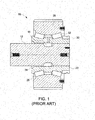
- an epicyclic gear system 10 is shown in cross-section in FIG. 1 to include a planet pin 12 about which a sleeve 22 is disposed.
- a planet gear 26 encompasses the sleeve 22 and is connected thereto through a rib ring 30.
- the planet pin 12 includes a groove 14 at a central location thereof.
- the sleeve 22 includes a tapered landing 24.
- the planet gear 26 has an indent 28.
- Rollers 32 are positioned between races found on an inner surface of the planet gear 26 and races found on an outer surface of the sleeve 22.
- the planet pin 12 is press fit to an upwind carrier plate (not shown).
- the gear system 10 acts as a double joint system that allows the planet gear 26 to align to a ring gear and a sun gear (not shown) despite planet pin's 12 tangential location and misalignment.
- Planetary gear systems such as system 10, find use in applications such as wind turbines. Other potential applications can be found in mill operations, the oil and gas industry, and the aviation industry.
- K ⁇ T Branch ⁇ N CP / T Nom
- T Branch is the torque for the gear with the heaviest load
- N CP is the number of planets
- T Nom is the total nominal torque for the system.
- K ⁇ 1.0
- gear teeth of the planetary gears are manufactured with a normal variance for such teeth.
- the thickness of the gear teeth may vary to an extent expected of tolerances for gear teeth.
- the pitch - the distance between adjacent gear teeth - also may vary.
- a planetary gear system that includes planetary gears that self-align as they mesh with a ring and a centralized sun gear would be welcome in the art.
- An embodiment of the invention includes a planetary gear system that includes a carrier body configured to receive planet gears, at least one pin received by the carrier body, and an insert positioned between the carrier body and the at least one pin.
- the flex means includes an inner ring, an outer ring, a pair of stabilizers connecting the inner and outer rings, and a stopper material positioned between the inner and outer rings.
- An embodiment of the invention includes a planetary gear system that includes a carrier body configured to receive planet gears, at least one pin received by the carrier body, and a compliant insert positioned within a cut-out portion formed on an interior surface of the carrier body.
- An embodiment of the invention includes a method for balancing a load on a planetary gear system that has a plurality of planet gears mounted on a carrier through a plurality of planet pins.
- the method includes preparing the carrier and providing flex means between the planet pins and the carrier, the flex means configured to enable movement of the planet pins in response to a force directed thereon.
- Various embodiments of the invention are intended to better accommodate pin misalignment relative to the central shaft, to more evenly distribute the force along the planet gear tooth width, and to more evenly share the loading among the various planet gears.
- FIG. 2 illustrates a planetary gear system 100 including a carrier 110 and a planet gear 120.
- the carrier 110 has a carrier body 112 which includes a sun gear opening 114, a plurality of planet gear openings 116, and a plurality of planet pin openings 118.
- the planet pin openings 118 serve as anchoring points for planet pins, about which each planet gear 120 is disposed. A portion of each planet gear 120 protrudes through a respective planet gear opening 116.
- FIG. 2 Although only a single planet gear 120 is illustrated in FIG. 2 , it is to be understood that four such planet gears 120 are intended for mounting on the carrier 110 of FIG. 2 . Further, it is to be understood that more or less than four planet gears 120 may be mounted on a carrier, depending upon the need and the configuration of the carrier.
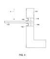
- FIGS. 3 and 4 illustrate the planetary gear system 100 of FIG. 2 in greater clarity.
- the planetary gear system 100 includes a spring insert 140 through which a planet pin 115 ( FIG. 4 ) may extend.
- the spring insert 140 is a toroid-shaped object that includes an outer flange 142 surrounding an inner flange 144.
- the spring insert 140 may be may be sized to cause an interference fit within the planet pin opening 118. It should be appreciated, however, that there are a plurality of attachment methods and mechanisms that can be used.
- One process for shrink fitting the spring insert 140 is to cool the insert down; the fit being created when the insert 140 warms back up.
- the spring insert inner flange 144 is configured to fit around the planet pin 115.
- the spring insert 140 provides flexure to the planet pins 115 to accommodate manufacturing tolerances and pin misalignments.
- the spring insert 140 is formed of a high strength metal, such as a high strength steel. Further, the geometry and the thinness of the spring insert 140 is such as to allow springiness, or flexure, of the insert. The springiness is translated to the planet pins 115. As shown in FIG. 4 , a bushing 149 may be located within the planet pin openings 118 to ensure the pin 115 remains in place.
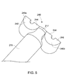
- FIG. 5 illustrates an embodiment of an insert and a planet pin, the planet pin 215 having an extrusion portion 217.
- the body of the pin 215 slopes down to the substantially rectangular-shaped extrusion portion 217.
- Engaged with the extrusion portion 217 is an insert 240 having a first part 240a and a second part 240b.
- Each of the first and second parts 240a, 240b has an outer flange 242 and an inner flange 244.
- the insert 240 acts similarly as the insert 140; the major difference being that the insert 240 flexes in only on direction, whereas the insert 140 has the capability of flexing in any direction.
- the portion of the pin 215 sloping toward the extrusion portion 217 is configured to accommodate the sloping portion of the first and second parts 240a, 240b. It should be understood, however, that the first and second parts 240a, 240b may be reversed such that the open ends of the outer and inner flanges 242, 244 face toward the sloping portion of the pin 215.
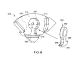
- FIG. 6 illustrates a carrier 310 according to an embodiment of the invention.
- the carrier 310 includes a carrier body 312 which has an inner surface 314. Cut-out portions 316, 318 are contiguous with one another and are located on the inner surface 314. A beveled edge 320 extends around the contour of at least the ring/neck cut-out portion 316 and may extend into the base cut-out portion 318. An oil passage is located in the middle of cut-out portion 316. A step-down line 322 may be located at a transition position between the ring/neck cut-out portion 316 and the base cut-out portion 318.
- An insert 340 is formed to fit within the cut out portions 316, 318.
- the insert 340 includes a ring portion 342 extending from a neck portion 344.
- the ring portion 342 is configured to receive a pin (not shown).
- a base portion 346 extends outwardly from a lower extent of the neck portion 344.
- On a back surface of the insert 340 is a beveled surface 348.
- the cut-out portion 318 and the insert 340 are configured and sized such that there is an interference fit therebetween.
- the cut-out portion 316 and the ring and neck portions 342, 344 are configured and sized such that there is a slight gap therebetween.
- the gap allows the ring portion 342 and the neck portion 344 to move slightly in the direction D within the cut-out portion 316 due to force placed on the pin (not shown).
- the gap between the ring and neck portions 342, 344 and the cut-out portion 316 is sized to allow normal operating torque but not extreme torque. When extreme torque is experienced, the ring portion 342 contacts the beveled edge 320 of the cut-out portion 316, allowing the carrier 310 to share the increased load.
- cut-out portions 316, 318 are created at all the pin positions for the carrier 310 such that inserts 340 are enabled to be fit within the cut-out portions.
- the insert 340 has geometry that is more compliant, or more flexible, than the material used to form the carrier 310. Further, the material forming the insert 340 may be a high strength material that has a greater yield strength than the material used to form the carrier 310. For example, the carrier 310 may be formed of cast iron, whereas the insert 340 may be formed of steel. The high strength of the insert 340, plus the shape of the insert, gives the insert suitable flexibility. The greater compliance of the insert 340 is translated to the pin held therein, thus assisting in providing a more even load share between pins.
- FIG. 7 illustrates a carrier 410 and an insert 440 according to an embodiment of the invention.
- the carrier 410 includes a carrier body 412 having a carrier inner surface 414.
- An insert cut-out portion 416 is located in the inner surface 414.
- the insert cut-out portion 416 includes a central cut-out portion 422 from which radially extend a plurality of ring cut-out portions 418 and neck cut-out portions 420.
- a beveled edge 424 extends along a periphery of the insert cut-out portion 416.
- Attachment openings 426 are located throughout the central cut-out portion 422.
- an insert 440 that includes a central portion 446 from which a plurality of neck portions 444 and ring portions 442 radially extend.
- the ring portions 442 are configured to each receive a pin (not shown).
- a plurality of attachment openings 448 is located in the central portion 446.
- the insert cut-out portion 416 and the insert 440 are sized and configured such that the central portion 446 does not move within the central cut-out portion 422, but the ring and neck portions 442, 444 can move slightly within, respectively, the ring cut-out and neck cut-out portions 418, 420.
- the central portion 446 may be sized to cause an interference fit within the central cut-out portion 422 such that there is no gap therebetween.
- attachment means may be placed through several attachment openings 448 and through respective attachment openings 426 to attach the insert 440 to the carrier 410.
- the gap between the ring and neck portions 442, 444 and the cut-out portions 418, 420 is sized to allow normal operating torque but not extreme torque. When extreme torque is experienced, the ring portion 442 contacts the beveled edge 424 of the cut-out portion 418, allowing the carrier 410 to share the increased load.
- insert 440 is more compliant, or more flexible, than the carrier 410.
- the material forming the insert 440 is a high strength material that has a greater yield strength than the material used to form the carrier 410.
- the carrier 410 may be formed of cast iron, whereas the insert 440 may be formed of steel. The greater compliance of the insert 440 is translated to the pin held therein, thus assisting in providing a more even load sharing among pins.
- the insert 440 is sized and positioned such that the carrier 410 is split into two portions.
- the insert may be sized and positioned such that the carrier need not be split into two portions to accommodate it.
- each carrier portion may accommodate an insert 440. Since the carrier 410 is in two portions, it has to be re-formed in such a way as to inhibit shear forces from separating the carrier portions from each other.
- a shear block 428 may be utilized, along with attachment means such as bolts or screws to recombine the carrier portions together once the inserts 440 have been put in place.
- FIG. 8 illustrates a carrier 510 and an insert 540 according to another embodiment of the invention.
- the carrier 510 includes an opening 513 having a wall 519. It is to be understood that the carrier 510 will have a plurality of openings 513, one being shown for ease of illustration.
- the openings 513 are located at a periphery of the carrier 510.
- the insert 540 includes an insert body 542 and first and second springs 550, 556.
- the insert body 542 includes a first surface 544 and an opposing second surface 546 as well as a pin opening 548.
- the first spring 550 has a first end 552 and an opposing second end 554.
- the second spring 556 has a first end 558 and an opposing second end 560.
- the insert 540 is placed within the opening 513 such that the first surface 544 contacts the wall 519.
- the insert 540 and the opening 513 may be configured and sized such that the insert 540 is under tension when in place within the opening 513.
- the first and second springs 550, 556 are sized and formed of a material that allows for flexing. When exposed to a tangential force, the first spring 550 flexes such that the first and second ends 552, 554 contact the second surface 546. The second spring 556 flexes such that the first and second ends 558, 560 contact the wall 519 of the opening 513. The flexing of the first and second springs 550, 556 is such that they contact one another at a midpoint M.
- the first and second springs 550, 556 provide flexure to the pin.
- the insert 540 will not exhibit flexure in response to a tangential force in a direction opposite direction D T1 . Nonetheless, the inserts 540 can be installed to allow for flexing in both tangential direction D T1 and the opposite direction. It should be further understood that more or less than two springs may be utilized with the insert body 542.
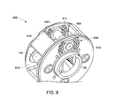
- FIG. 9 illustrates a planetary gear system 600 including a carrier 610 and inserts 640 according to an embodiment of the invention.
- the carrier 610 has a carrier body 612 with a plurality of planetary gear openings 613 through which planetary gears, such as the planetary gear 26, extend.
- the carrier 610 also has a plurality of carrier openings 614.
- the openings 614 are paired on opposing sides of the carrier body 612.
- Each insert 640 includes an insert ring 642 from which extend a plurality of insert springs 644.
- the insert rings 642 are configured to receive planet pins 115.
- the inserts 640 are sized and shaped to form an interference fit with the openings 614.
- the springs 644 are sized and formed of a material that allow for flexing in response to a tangential force exerted on the pins 115.
- the springs 644 may be S-shaped or shaped otherwise, and they may be formed of steel.
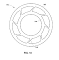
- FIG. 10 illustrates an insert 740 according to another embodiment of the invention.
- the insert 740 is configured and sized to be interference fit within a planet pin opening 118.
- the insert 740 includes an outer ring 742 connected to an inner ring 744 by a plurality of springs 746.
- the inner ring 744 is sized to receive a planet pin, such as pin 115.
- the springs 746 flex in response to a force directed at the pin.
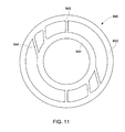
- FIG. 11 illustrates an insert 840 according to an embodiment of the invention, which like insert 740, is interference fit within a planet pin opening 118.
- the insert 840 includes an outer ring 842 separated from an inner ring 844.
- the outer ring 842 is connected to the inner ring 842 with a pair of stabilizers 845 and a plurality of springs 846.
- the inner ring 844 is sized to receive a planet pin, such as pin 115.
- the springs 846 flex in response to a force directed at the planet pin in a first direction.
- the stabilizers 845 extend along a midline of the insert 840.
- the stabilizers 845 inhibit flexing in response to a force directed at the planet pin in a second direction.
- the insert 840 can be installed in a planet pin opening 118 such that the first direction is a tangential direction and the second direction is a radial direction. In other words, the insert 840 can be installed such that the stabilizers 845 inhibit force in a radial direction on the planet pin.
- FIG. 12 illustrates an insert 940 according to an embodiment of the invention.
- the insert 940 is sized to be interference fit within a planetary pin opening 118.
- the insert 940 includes an outer ring 942 connected to an inner ring 944 by a plurality of springs 946.
- the inner ring 944 is sized to receive a planet pin, such as planet pin 115.
- the springs 946 are overloaded on one side of the insert 940.
- the springs 946 allow flexing of the planet pin in response to a force on the pin in a first direction.
- the insert 940 can be installed such that the springs 946 foster flexing in the first tangential direction but inhibit flexing in a second radial direction. Further, the overloading of the springs 946 on one side of the insert 940 allows greater flexing from force in one tangential direction D T1 as opposed to force applied in an opposite tangential direction D T2 . Nonetheless, the inserts 940, like the inserts 540, can be installed to allow for flexing in both tangential directions D T1 and D T2 .
- pairs of the inserts 940 on opposite ends of one planet pin may be reversed so that the springs 946 are overloaded on the D T2 direction side on one end of the planet pin and overloaded on the D T1 direction side on the other end of the planet pin.
- FIG. 13 illustrates a partial carrier 610 and an insert 1040 according to an embodiment of the invention.
- a complete carrier 610 has a plurality of planetary gear openings 613 to receive planetary gears. Further, the carrier 610 has carrier openings 614 to accommodate inserts 1040. As shown, an opening 614 is formed on one side of the carrier 610 but not the other. It should be understood that the openings 614 may be formed on opposing sides of the carrier 610 to accommodate inserts 1040.
- the insert 1040 which is sized to cause an interference fit within an opening 614, includes an outer ring 1042 connected to an inner ring 1044 by a pair of stabilizers 1045.
- the inner ring 1044 is sized to receive a planet pin 115.
- Filling in the space between the outer and inner rings 1042, 1044 is a stopper material 1049.
- the outer and inner rings 1042, 1044 are formed to be more compliant or flexible than the stopper material 1049.
- the outer and inner rings 1042, 1044 may be formed of a material having a higher strength than the stopper material 1049.
- the outer and inner rings 1042, 1044 may be formed of steel, while the stopper material 1049 is formed of cast iron.
- the greater compliancy of the outer and inner rings 1042, 1044 allow for flexing, which translates into tangential movement of the pin 115.
- the outer and inner rings 1042, 1044 can flex in response to normal, operating torque.
- the force of the torque is transferred to the stopper material 1049, thus causing the carrier to share in the load.
- FIG. 14 illustrates a partial carrier 610 and an insert 1140 according to an embodiment of the invention.
- the insert 1140 is configured and sized to be interference fit within the carrier openings 614.
- an opening 614 is formed on one side of the carrier 610 but not the other. It should be understood that the openings 614 may be formed on opposing sides of the carrier 610 to accommodate inserts 1140.
- the insert 1140 includes an outer ring 1142 connected to an inner ring 1144 by a pair of stabilizers 1145 and stiffeners 1147.
- the inner ring 1144 is sized to receive a planet pin 115.
- Filling in the space between the outer and inner rings 1142, 1144 is a stopper material 1149.
- the outer and inner rings 1142, 1144 are formed to be more compliant or flexible than the stopper material 1149.
- the outer and inner rings 1142, 1144 may be formed of steel, while the stopper material 1149 is formed of cast iron.
- a distinction between the insert 1040 ( FIG. 13 ) and insert 1140 is the length of the stabilizers 1145. The longer stabilizers 1145 of insert 1140 allow for greater compliance in response to a tangentially directed force.
- the greater compliancy of the outer and inner rings 1142, 1144 allow for flexing, which translates into tangential movement of the pin 115.
- the outer and inner rings 1142, 1144 can flex in response to normal, operating torque.
- the force of the torque is combatted by the stiffeners 1147 and transferred to the stopper material 1149, thus causing the carrier to share in the load.
- FIG. 15 illustrates a partial carrier 1210 and an insert 1240 according to an embodiment of the invention.
- the carrier 1210 has a carrier body 1212 that includes a plurality of carrier cut-outs 1213. Each cut-out 713 includes a wall 1216. An opening is formed in the carrier cut-outs 1213 to receive a planet pin 115.
- the insert 1240 includes a ring 1242 sized and configured to receive the planet pin 115. Further, the insert 1240 includes a pair of stabilizers 1245 connected to the ring 1242 by a pair of stiffeners 1247. The stabilizers 1245 are not intimate with the cut-out walls 716 except at the comers. This arrangement allows the stabilizers to flex in response to a force tangentially directed on the pin 115, absorbing some of the torque. Filling in the remaining space within the cut-outs 1213 is a stopper material (not shown). The insert 1240 can withstand normal, operating torque. If extreme torque is experienced by the pin 115, the stabilizers 1245 will flex to a certain extent to absorb some of the torque, and then the remaining torque will be taken up by the stiffeners 1247 and the stopper material.
- a carrier is prepared.
- Preparation of the carrier may include boring planet pin openings, such as opening 118, within a carrier.
- Preparation of the carrier also may include creating cut-outs within the carrier, such as cut-outs 316, 318 or cut-out 416 or cut-out 1213.
- preparation of the carrier also may include splitting the carrier into two parts.
- Preparation of the carrier also may include creating slots, like slots 513, or carrier openings 614.
- Preparation of the carrier also may include forming the carrier, or at least one part of the carrier, out of a high strength material like steel.
- a flex means is provided to the carrier.
- Provision of a flex means may include fitting spring inserts, like spring inserts 140, 240, 740, 840, or 940 within planet pin openings, like openings 118.
- Provision of a flex means may include adding compliant inserts, like compliant inserts 340 or compliant inserts 440, into, respectively, cut-outs 316, 318 or cut-outs 416.
- Provision of flex means may include adding inserts 540 into slots 513.
- Provision of flex means may include fitting inserts, like inserts 640, 1040, or 1140 within carrier openings 614.
- Provision of flex means may include fitting inserts 1240 within cut-outs 1213.
Landscapes
- Engineering & Computer Science (AREA)
- General Engineering & Computer Science (AREA)
- Mechanical Engineering (AREA)
- Retarders (AREA)
- General Details Of Gearings (AREA)
Abstract
a carrier body (112) configured to receive planet gears (120);
at least one pin (115) received by said carrier body; and
an insert (140, 240, 540, 640, 740, 840, 940, 1040, 1140, 1240) positioned between said carrier body and said at least one pin.

Description
- The invention relates generally to a gear system, and more particularly, to a gear system with planet pins, for anchoring planet gears, which centralize the load on each of the planet gears and balance the load between the planet gears.
- Planetary gear systems are known. Examples of planetary gear systems may be found in
U.S. Patents Nos. 6,994,651 and7,297,086 andU.S. Patents Pubs. 2011/0039654 and2011/0053730 . - One such system, an
epicyclic gear system 10, is shown in cross-section inFIG. 1 to include aplanet pin 12 about which asleeve 22 is disposed. Aplanet gear 26 encompasses thesleeve 22 and is connected thereto through arib ring 30. Theplanet pin 12 includes agroove 14 at a central location thereof. Thesleeve 22 includes atapered landing 24. Theplanet gear 26 has an indent 28.Rollers 32 are positioned between races found on an inner surface of theplanet gear 26 and races found on an outer surface of thesleeve 22. - The
planet pin 12 is press fit to an upwind carrier plate (not shown). Thegear system 10 acts as a double joint system that allows theplanet gear 26 to align to a ring gear and a sun gear (not shown) despite planet pin's 12 tangential location and misalignment. There is agap 24 between thesleeve 22 and theplanet pin 12 to allow relative motion and adjustment of theplanet pin 12 for rotational and tangential dislocation due to forces being exerted on theplanet gear 26. - Planetary gear systems, such as
system 10, find use in applications such as wind turbines. Other potential applications can be found in mill operations, the oil and gas industry, and the aviation industry. - For known planetary gear systems utilizing multiple planet gears, a problem that has developed is the creation of an unbalanced load among the planet gears. As a rotating member - depending upon the gear system, the ring gear, the carrier, or the sun gear may supply an input to the gearbox - rotates, it places a force, or a load, on the planet gears. The load factor Kγ of a planetary gear system may be defmed as :

- Where TBranch is the torque for the gear with the heaviest load, NCP is the number of planets, and TNom is the total nominal torque for the system. Ideally, the force should be the same on each planet gear, i.e., Kγ = 1.0, thereby creating a balanced load. However, for a variety of reasons planetary gear systems often suffer from unbalanced loads.
- One reason for unbalanced loads is that the gear teeth of the planetary gears are manufactured with a normal variance for such teeth. For example, the thickness of the gear teeth may vary to an extent expected of tolerances for gear teeth. Additionally, the pitch - the distance between adjacent gear teeth - also may vary.
- Under normal manufacturing practices, the planet pin holes in the carrier will be drilled away from their centric true positions. This is due to manufacturing tolerance limitations, complexity of the machined part, measuring capability, and human error. This scenario causes (1) planet pins to be out of alignment from the central shaft, and (2) each planet gear to carry a load different from what they are designed for. Under normal loading conditions, the carrier may twist slightly. This twist may contribute to the misalignment between the planet gears and the ring gear/sun gear assembly. Depending on the number of planets and their respective tolerances, loads experienced by any single planet can increase dramatically, as much as 2X or more.
- Reducing the load factor Kγ on a gear system will allow smaller system components to be utilized or allow greater loads on system components than are currently placed. A more evenly distributed shared load may allow for an increase in the gearbox torque density.
- With some of these concerns in mind, a planetary gear system that includes planetary gears that self-align as they mesh with a ring and a centralized sun gear would be welcome in the art.
- An embodiment of the invention includes a planetary gear system that includes a carrier body configured to receive planet gears, at least one pin received by the carrier body, and an insert positioned between the carrier body and the at least one pin.
- In an aspect, the flex means includes an inner ring, an outer ring, a pair of stabilizers connecting the inner and outer rings, and a stopper material positioned between the inner and outer rings.
- An embodiment of the invention includes a planetary gear system that includes a carrier body configured to receive planet gears, at least one pin received by the carrier body, and a compliant insert positioned within a cut-out portion formed on an interior surface of the carrier body.
- An embodiment of the invention includes a method for balancing a load on a planetary gear system that has a plurality of planet gears mounted on a carrier through a plurality of planet pins. The method includes preparing the carrier and providing flex means between the planet pins and the carrier, the flex means configured to enable movement of the planet pins in response to a force directed thereon.
- Various features, aspects and advantages of the present invention may be further understood and/or illustrated when the following detailed description is considered along with the attached drawings, in which:
-
FIG. 1 is a cross-sectional view of a conventional planet gear system. -
FIG. 2 is a schematic view illustrating a carrier and one planet gear in accordance with an embodiment of the invention. -
FIG. 3 is a schematic partial view of the planet gear ofFIG. 2 in accordance with an embodiment of the invention. -
FIG. 4 is a cross-sectional view of the planet gear ofFIG. 3 taken along line IV-IV and including a pin. -
FIG. 5 is a schematic view of a planet pin in accordance with an embodiment of the invention. -
FIG. 6 is a partial perspective view of a carrier and an insert in accordance with an embodiment of the invention. -
FIG. 7 is a perspective view of a carrier and an insert in accordance with an embodiment of the invention. -
FIG. 8 is a perspective view of a carrier and an insert in accordance with an embodiment of the invention. -
FIG. 9 is a perspective view of a carrier and an insert in accordance with an embodiment of the invention. -
FIG. 10 is a schematic view of an insert in accordance with an embodiment of the invention. -
FIG. 11 is a schematic view of an insert in accordance with an embodiment of the invention. -
FIG. 12 is a schematic view of an insert in accordance with an embodiment of the invention. -
FIG. 13 is a partial perspective view of a carrier and insert in accordance with an embodiment of the invention. -
FIG. 14 is a partial perspective view of a carrier and insert in accordance with an embodiment of the invention. -
FIG. 15 is a partial cross-sectional view of a carrier and insert in accordance with an embodiment of the invention. -
FIG. 16 illustrates a process for balancing a load on a planetary gear system. - The present specification provides certain definitions and methods to better define the embodiments and aspects of the invention and to guide those of ordinary skill in the art in the practice of its fabrication. Provision, or lack of the provision, of a definition for a particular term or phrase is not meant to imply any particular importance, or lack thereof; rather, and unless otherwise noted, terms are to be understood according to conventional usage by those of ordinary skill in the relevant art.
- Unless defined otherwise, technical and scientific terms used herein have the same meaning as is commonly understood by one of skill in the art to which this invention belongs. The terms "first", "second", and the like, as used herein do not denote any order, quantity, or importance, but rather are used to distinguish one element from another. Also, the terms "a" and "an" do not denote a limitation of quantity, but rather denote the presence of at least one of the referenced item, and the terms "front", "back", "bottom", and/or "top", unless otherwise noted, are merely used for convenience of description, and are not limited to any one position or spatial orientation. If ranges are disclosed, the endpoints of all ranges directed to the same component or property are inclusive and independently combinable.
- The modifier "about" used in connection with a quantity is inclusive of the stated value and has the meaning dictated by the context (e.g., includes the degree of error associated with measurement of the particular quantity). Reference throughout the specification to "one embodiment", "another embodiment", "an embodiment", and so forth, means that a particular element (e.g., feature, structure, and/or characteristic) described in connection with the embodiment is included in at least one embodiment described herein, and may or may not be present in other embodiments. In addition, it is to be understood that the described inventive features may be combined in any suitable manner in the various embodiments.
- Various embodiments of the invention are intended to better accommodate pin misalignment relative to the central shaft, to more evenly distribute the force along the planet gear tooth width, and to more evenly share the loading among the various planet gears.
-
FIG. 2 illustrates aplanetary gear system 100 including acarrier 110 and aplanet gear 120. Thecarrier 110 has acarrier body 112 which includes asun gear opening 114, a plurality ofplanet gear openings 116, and a plurality ofplanet pin openings 118. Theplanet pin openings 118 serve as anchoring points for planet pins, about which eachplanet gear 120 is disposed. A portion of eachplanet gear 120 protrudes through a respectiveplanet gear opening 116. Although only asingle planet gear 120 is illustrated inFIG. 2 , it is to be understood that four such planet gears 120 are intended for mounting on thecarrier 110 ofFIG. 2 . Further, it is to be understood that more or less than fourplanet gears 120 may be mounted on a carrier, depending upon the need and the configuration of the carrier. -
FIGS. 3 and4 illustrate theplanetary gear system 100 ofFIG. 2 in greater clarity. As shown, theplanetary gear system 100 includes aspring insert 140 through which a planet pin 115 (FIG. 4 ) may extend. Specifically, thespring insert 140 is a toroid-shaped object that includes anouter flange 142 surrounding aninner flange 144. Thespring insert 140 may be may be sized to cause an interference fit within theplanet pin opening 118. It should be appreciated, however, that there are a plurality of attachment methods and mechanisms that can be used. One process for shrink fitting thespring insert 140 is to cool the insert down; the fit being created when theinsert 140 warms back up. The spring insertinner flange 144 is configured to fit around theplanet pin 115. Thespring insert 140 provides flexure to the planet pins 115 to accommodate manufacturing tolerances and pin misalignments. Thespring insert 140 is formed of a high strength metal, such as a high strength steel. Further, the geometry and the thinness of thespring insert 140 is such as to allow springiness, or flexure, of the insert. The springiness is translated to the planet pins 115. As shown inFIG. 4 , abushing 149 may be located within theplanet pin openings 118 to ensure thepin 115 remains in place. - As a force F is applied to the
planet pin 115, one side of theinner flange 144 will flex toward theouter flange 142. This flexure is elastic; as the force F is removed from thepin 115, theflanges flanges carrier body 112, it should be understood that the open ends of theflanges carrier body 112. -
FIG. 5 illustrates an embodiment of an insert and a planet pin, theplanet pin 215 having anextrusion portion 217. The body of thepin 215 slopes down to the substantially rectangular-shapedextrusion portion 217. Engaged with theextrusion portion 217 is aninsert 240 having afirst part 240a and asecond part 240b. Each of the first andsecond parts outer flange 242 and aninner flange 244. Theinsert 240 acts similarly as theinsert 140; the major difference being that theinsert 240 flexes in only on direction, whereas theinsert 140 has the capability of flexing in any direction. As shown, the portion of thepin 215 sloping toward theextrusion portion 217 is configured to accommodate the sloping portion of the first andsecond parts second parts inner flanges pin 215. -
FIG. 6 illustrates acarrier 310 according to an embodiment of the invention. Thecarrier 310 includes acarrier body 312 which has aninner surface 314. Cut-outportions inner surface 314. Abeveled edge 320 extends around the contour of at least the ring/neck cut-outportion 316 and may extend into the base cut-outportion 318. An oil passage is located in the middle of cut-outportion 316. A step-downline 322 may be located at a transition position between the ring/neck cut-outportion 316 and the base cut-outportion 318. - An
insert 340 is formed to fit within the cut outportions insert 340 includes aring portion 342 extending from aneck portion 344. Thering portion 342 is configured to receive a pin (not shown). Abase portion 346 extends outwardly from a lower extent of theneck portion 344. On a back surface of theinsert 340 is abeveled surface 348. - There is no gap between the
insert 340 and the cut-outportion 318 below the step-downline 322. Thus, properly configured, the cut-outportion 318 and theinsert 340 are configured and sized such that there is an interference fit therebetween. The cut-outportion 316 and the ring andneck portions ring portion 342 and theneck portion 344 to move slightly in the direction D within the cut-outportion 316 due to force placed on the pin (not shown). The gap between the ring andneck portions portion 316 is sized to allow normal operating torque but not extreme torque. When extreme torque is experienced, thering portion 342 contacts thebeveled edge 320 of the cut-outportion 316, allowing thecarrier 310 to share the increased load. - Although only one pin position is shown in
FIG. 6 , it should be understood that cut-outportions carrier 310 such that inserts 340 are enabled to be fit within the cut-out portions. - The
insert 340 has geometry that is more compliant, or more flexible, than the material used to form thecarrier 310. Further, the material forming theinsert 340 may be a high strength material that has a greater yield strength than the material used to form thecarrier 310. For example, thecarrier 310 may be formed of cast iron, whereas theinsert 340 may be formed of steel. The high strength of theinsert 340, plus the shape of the insert, gives the insert suitable flexibility. The greater compliance of theinsert 340 is translated to the pin held therein, thus assisting in providing a more even load share between pins. -
FIG. 7 illustrates acarrier 410 and aninsert 440 according to an embodiment of the invention. Thecarrier 410 includes acarrier body 412 having a carrierinner surface 414. An insert cut-outportion 416 is located in theinner surface 414. The insert cut-outportion 416 includes a central cut-outportion 422 from which radially extend a plurality of ring cut-outportions 418 and neck cut-outportions 420. Abeveled edge 424 extends along a periphery of the insert cut-outportion 416.Attachment openings 426 are located throughout the central cut-outportion 422. - Further illustrated in
FIG. 7 is aninsert 440 that includes acentral portion 446 from which a plurality ofneck portions 444 andring portions 442 radially extend. Thering portions 442 are configured to each receive a pin (not shown). A plurality ofattachment openings 448 is located in thecentral portion 446. As shown, there are four ring andneck portions portions - The insert cut-out
portion 416 and theinsert 440 are sized and configured such that thecentral portion 446 does not move within the central cut-outportion 422, but the ring andneck portions portions central portion 446 may be sized to cause an interference fit within the central cut-outportion 422 such that there is no gap therebetween. Alternatively, attachment means may be placed throughseveral attachment openings 448 and throughrespective attachment openings 426 to attach theinsert 440 to thecarrier 410. - Through either attachment scenario, a gap exists between the ring and neck cut-out
portions neck portions neck portions neck portions portions ring portion 442 contacts thebeveled edge 424 of the cut-outportion 418, allowing thecarrier 410 to share the increased load. - The shape of
insert 440 is more compliant, or more flexible, than thecarrier 410. The material forming theinsert 440 is a high strength material that has a greater yield strength than the material used to form thecarrier 410. For example, thecarrier 410 may be formed of cast iron, whereas theinsert 440 may be formed of steel. The greater compliance of theinsert 440 is translated to the pin held therein, thus assisting in providing a more even load sharing among pins. - The
insert 440 is sized and positioned such that thecarrier 410 is split into two portions. Alternatively, as shown inFIG. 6 , the insert may be sized and positioned such that the carrier need not be split into two portions to accommodate it. Although only one carrier portion and oneinsert 440 are illustrated, it should be understood that each carrier portion may accommodate aninsert 440. Since thecarrier 410 is in two portions, it has to be re-formed in such a way as to inhibit shear forces from separating the carrier portions from each other. Ashear block 428 may be utilized, along with attachment means such as bolts or screws to recombine the carrier portions together once theinserts 440 have been put in place. -
FIG. 8 illustrates acarrier 510 and aninsert 540 according to another embodiment of the invention. As shown, thecarrier 510 includes anopening 513 having awall 519. It is to be understood that thecarrier 510 will have a plurality ofopenings 513, one being shown for ease of illustration. Theopenings 513 are located at a periphery of thecarrier 510. Theinsert 540 includes aninsert body 542 and first andsecond springs insert body 542 includes afirst surface 544 and an opposingsecond surface 546 as well as apin opening 548. Thefirst spring 550 has afirst end 552 and an opposingsecond end 554. Thesecond spring 556 has afirst end 558 and an opposingsecond end 560. - The
insert 540 is placed within theopening 513 such that thefirst surface 544 contacts thewall 519. Specifically, theinsert 540 and theopening 513 may be configured and sized such that theinsert 540 is under tension when in place within theopening 513. The first andsecond springs first spring 550 flexes such that the first and second ends 552, 554 contact thesecond surface 546. Thesecond spring 556 flexes such that the first and second ends 558, 560 contact thewall 519 of theopening 513. The flexing of the first andsecond springs second springs insert 540 will not exhibit flexure in response to a tangential force in a direction opposite direction DT1. Nonetheless, theinserts 540 can be installed to allow for flexing in both tangential direction DT1 and the opposite direction. It should be further understood that more or less than two springs may be utilized with theinsert body 542. -
FIG. 9 illustrates aplanetary gear system 600 including acarrier 610 and inserts 640 according to an embodiment of the invention. Thecarrier 610 has acarrier body 612 with a plurality ofplanetary gear openings 613 through which planetary gears, such as theplanetary gear 26, extend. Thecarrier 610 also has a plurality ofcarrier openings 614. Theopenings 614 are paired on opposing sides of thecarrier body 612. - Each
insert 640 includes aninsert ring 642 from which extend a plurality of insert springs 644. The insert rings 642 are configured to receive planet pins 115. Theinserts 640 are sized and shaped to form an interference fit with theopenings 614. Thesprings 644 are sized and formed of a material that allow for flexing in response to a tangential force exerted on thepins 115. Thesprings 644 may be S-shaped or shaped otherwise, and they may be formed of steel. -
FIG. 10 illustrates aninsert 740 according to another embodiment of the invention. Theinsert 740 is configured and sized to be interference fit within aplanet pin opening 118. Theinsert 740 includes anouter ring 742 connected to aninner ring 744 by a plurality ofsprings 746. Theinner ring 744 is sized to receive a planet pin, such aspin 115. Thesprings 746 flex in response to a force directed at the pin. -
FIG. 11 illustrates aninsert 840 according to an embodiment of the invention, which likeinsert 740, is interference fit within aplanet pin opening 118. Theinsert 840 includes anouter ring 842 separated from aninner ring 844. Theouter ring 842 is connected to theinner ring 842 with a pair ofstabilizers 845 and a plurality ofsprings 846. Theinner ring 844 is sized to receive a planet pin, such aspin 115. Thesprings 846 flex in response to a force directed at the planet pin in a first direction. As shown, thestabilizers 845 extend along a midline of theinsert 840. Thestabilizers 845 inhibit flexing in response to a force directed at the planet pin in a second direction. Theinsert 840 can be installed in a planet pin opening 118 such that the first direction is a tangential direction and the second direction is a radial direction. In other words, theinsert 840 can be installed such that thestabilizers 845 inhibit force in a radial direction on the planet pin. -
FIG. 12 illustrates aninsert 940 according to an embodiment of the invention. Theinsert 940 is sized to be interference fit within aplanetary pin opening 118. Theinsert 940 includes anouter ring 942 connected to aninner ring 944 by a plurality ofsprings 946. Theinner ring 944 is sized to receive a planet pin, such asplanet pin 115. - The
springs 946 are overloaded on one side of theinsert 940. Thesprings 946 allow flexing of the planet pin in response to a force on the pin in a first direction. Theinsert 940 can be installed such that thesprings 946 foster flexing in the first tangential direction but inhibit flexing in a second radial direction. Further, the overloading of thesprings 946 on one side of theinsert 940 allows greater flexing from force in one tangential direction DT1 as opposed to force applied in an opposite tangential direction DT2. Nonetheless, theinserts 940, like theinserts 540, can be installed to allow for flexing in both tangential directions DT1 and DT2. For example, pairs of theinserts 940 on opposite ends of one planet pin may be reversed so that thesprings 946 are overloaded on the DT2 direction side on one end of the planet pin and overloaded on the DT1 direction side on the other end of the planet pin. -
FIG. 13 illustrates apartial carrier 610 and aninsert 1040 according to an embodiment of the invention. Acomplete carrier 610 has a plurality ofplanetary gear openings 613 to receive planetary gears. Further, thecarrier 610 hascarrier openings 614 to accommodateinserts 1040. As shown, anopening 614 is formed on one side of thecarrier 610 but not the other. It should be understood that theopenings 614 may be formed on opposing sides of thecarrier 610 to accommodateinserts 1040. - The
insert 1040, which is sized to cause an interference fit within anopening 614, includes anouter ring 1042 connected to aninner ring 1044 by a pair ofstabilizers 1045. Theinner ring 1044 is sized to receive aplanet pin 115. Filling in the space between the outer andinner rings stopper material 1049. The outer andinner rings stopper material 1049. The outer andinner rings stopper material 1049. For example, the outer andinner rings stopper material 1049 is formed of cast iron. Upon application of a tangential force, the greater compliancy of the outer andinner rings pin 115. The outer andinner rings stopper material 1049, thus causing the carrier to share in the load. -
FIG. 14 illustrates apartial carrier 610 and aninsert 1140 according to an embodiment of the invention. Theinsert 1140 is configured and sized to be interference fit within thecarrier openings 614. As shown, anopening 614 is formed on one side of thecarrier 610 but not the other. It should be understood that theopenings 614 may be formed on opposing sides of thecarrier 610 to accommodateinserts 1140. - The
insert 1140 includes anouter ring 1142 connected to aninner ring 1144 by a pair ofstabilizers 1145 andstiffeners 1147. Theinner ring 1144 is sized to receive aplanet pin 115. Filling in the space between the outer andinner rings stopper material 1149. The outer andinner rings stopper material 1149. For example, the outer andinner rings stopper material 1149 is formed of cast iron. A distinction between the insert 1040 (FIG. 13 ) andinsert 1140 is the length of thestabilizers 1145. Thelonger stabilizers 1145 ofinsert 1140 allow for greater compliance in response to a tangentially directed force. - Upon application of a tangential force, the greater compliancy of the outer and
inner rings pin 115. The outer andinner rings stiffeners 1147 and transferred to thestopper material 1149, thus causing the carrier to share in the load. -
FIG. 15 illustrates apartial carrier 1210 and aninsert 1240 according to an embodiment of the invention. Thecarrier 1210 has acarrier body 1212 that includes a plurality of carrier cut-outs 1213. Each cut-out 713 includes awall 1216. An opening is formed in the carrier cut-outs 1213 to receive aplanet pin 115. - The
insert 1240 includes aring 1242 sized and configured to receive theplanet pin 115. Further, theinsert 1240 includes a pair ofstabilizers 1245 connected to thering 1242 by a pair ofstiffeners 1247. Thestabilizers 1245 are not intimate with the cut-out walls 716 except at the comers. This arrangement allows the stabilizers to flex in response to a force tangentially directed on thepin 115, absorbing some of the torque. Filling in the remaining space within the cut-outs 1213 is a stopper material (not shown). Theinsert 1240 can withstand normal, operating torque. If extreme torque is experienced by thepin 115, thestabilizers 1245 will flex to a certain extent to absorb some of the torque, and then the remaining torque will be taken up by thestiffeners 1247 and the stopper material. - Next, with particular reference to
FIG. 16 and general reference toFIGS. 2-15 , will be described a method for balancing a load on a planetary gear system. At step 1700 a carrier is prepared. Preparation of the carrier may include boring planet pin openings, such asopening 118, within a carrier. Preparation of the carrier also may include creating cut-outs within the carrier, such as cut-outs out 1213. With regard to cut-out 416, preparation of the carrier also may include splitting the carrier into two parts. Preparation of the carrier also may include creating slots, likeslots 513, orcarrier openings 614. Preparation of the carrier also may include forming the carrier, or at least one part of the carrier, out of a high strength material like steel. - At step 1705 a flex means is provided to the carrier. Provision of a flex means may include fitting spring inserts, like spring inserts 140, 240, 740, 840, or 940 within planet pin openings, like
openings 118. Provision of a flex means may include adding compliant inserts, likecompliant inserts 340 orcompliant inserts 440, into, respectively, cut-outs outs 416. Provision of flex means may include addinginserts 540 intoslots 513. Provision of flex means may include fitting inserts, likeinserts carrier openings 614. Provision of flex means may includefitting inserts 1240 within cut-outs 1213. - The embodiments of the invention described herein will enable an increase in torque capacity, as well as an improved load distribution, for a planetary gearbox. Further, these enhancements are enabled with a minimum of overall mass impact on the gearbox.
- While the invention has been described in detail in connection with only a limited number of embodiments, it should be readily understood that the invention is not limited to such disclosed embodiments. Rather, the invention can be modified to incorporate any number of variations, alterations, substitutions or equivalent arrangements not heretofore described, but which are commensurate with the spirit and scope of the invention. For example, while embodiments have been described in terms that may initially connote singularity, it should be appreciated that multiple components may be utilized. Additionally, while various embodiments of the invention have been described, it is to be understood that aspects of the invention may include only some of the described embodiments. Accordingly, the invention is not to be seen as limited by the foregoing description, but is only limited by the scope of the appended claims.
- Various aspects and embodiments of the present invention are defined by the following numbered clauses:
- 1. A planetary gear system, comprising:
- a carrier body configured to receive planet gears;
- at least one pin received by said carrier body; and
- an insert positioned between said carrier body and said at least one pin.
- 2. The planetary gear system of clause 1, wherein said insert is positioned within an opening within said carrier body.
- 3. The planetary gear system of any preceding clause, wherein said insert comprises an inner and an outer flange.
- 4. The planetary gear system of any preceding clause, wherein said at least one pin includes an extrusion portion configured to receive said insert.
- 5. The planetary gear system of any preceding clause, wherein said insert includes an inner ring connected to an outer ring with a plurality of springs.
- 6. The planetary gear system of any preceding clause, wherein the insert includes at least one stabilizer.
- 7. The planetary gear system of any preceding clause, wherein said opening within said carrier body comprises a wall and said insert includes an insert body and at least two springs.
- 8. The planetary gear system of any preceding clause, wherein said insert includes an insert ring and a plurality of springs positioned within said opening within said carrier body.
- 9. The planetary gear system of any preceding clause, wherein said plurality of springs are S-shaped.
- 10. The planetary gear system of any preceding clause, wherein said insert comprises:
- an inner ring;
- an outer ring;
- a pair of stabilizers connecting said inner and outer rings; and
- a stopper material positioned between said inner and outer rings.
- 11. The planetary gear system of any preceding clause, wherein said inner and outer rings and said pair of stabilizers are formed of a higher strength material than said stopper material.
- 12. The planetary gear system of any preceding clause, wherein said insert includes a ring and a pair of stabilizers, said insert fitting within a cut-out portion within said carrier body.
- 13. A planetary gear system, comprising:
- a carrier body configured to receive planet gears;
- at least one pin received by said carrier body; and
- a compliant insert positioned within a cut-out portion formed on an interior surface of said carrier body.
- 14. The planetary gear system of any preceding clause, wherein said compliant insert comprises:
- a ring portion configured to receive the at least one pin;
- a neck portion, wherein said ring and neck portions are separated from a wall of said cut-out portion by a gap; and
- a third portion positioned within said cut-out portion.
- 15. The planetary gear system of any preceding clause, wherein said third portion is a central portion attached to said carrier body and said ring and neck portions extend radially therefrom.
- 16. A method of balancing a load on a planetary gear system comprising a plurality of planet gears mounted on a carrier through a plurality of planet pins, the method comprising:
- preparing the carrier; and
- providing flex means between said planet pins and said carrier, said flex means configured to enable movement of said planet pins in response to a force directed thereon.
- 17. The method of any preceding clause, wherein said providing flex means comprises providing an insert or a compliant insert.
- 18. The method of any preceding clause, wherein providing a compliant insert comprises:
- providing ring portions configured to each receive one of the plurality of planet pins;
- providing a neck portion, wherein said ring and neck portions are separated from a wall of said cut-out portion by a gap; and
- providing a third portion positioned within said cut-out portion.
- 19. The method of any preceding clause, wherein providing an insert comprises providing an inner and an outer flange.
- 20. The method of any preceding clause, wherein providing an insert comprises providing an inner ring connected to an outer ring with a plurality of springs.
Claims (9)
- A planetary gear system (100), comprising:a carrier body (112) configured to receive planet gears (120);at least one pin (115) received by said carrier body; andan insert (140, 240, 540, 640, 740, 840, 940, 1040, 1140, 1240) positioned between said carrier body and said at least one pin.
- The planetary gear system of claim 1, wherein said insert is positioned within an opening (118, 513) within said carrier body.
- The planetary gear system of any preceding claim, wherein said insert comprises an inner (144, 244) and an outer (142, 242) flange.
- The planetary gear system of any preceding claim, wherein said insert includes an inner ring (744, 844, 944, 1044, 1144) connected to an outer ring (742, 842, 942, 1042, 1142) with a plurality of springs(746, 846, 946, 1046, 1146).
- The planetary gear system of any preceding claim, wherein said opening within said carrier body comprises a wall (519) and said insert (540) includes an insert body (542) and at least two springs (550, 556).
- The planetary gear system of any preceding claim, wherein said insert (640) includes an insert ring (642) and a plurality of springs (644) positioned within said opening within said carrier body.
- The planetary gear system of any preceding claim, wherein said insert (840) includes a ring (842) and a pair of stabilizers (845), said insert fitting within a cut-out portion within said carrier body.
- The planetary gear system of any preceding claim, wherein said insert (1040, 1140) comprises:an inner ring (1044, 144);an outer ring (1042, 1142);a pair of stabilizers (1045, 1145) connecting said inner and outer rings; anda stopper material (1049, 1149) positioned between said inner and outer rings.
- A planetary gear system (100), comprising:a carrier body (312, 412) configured to receive planet gears (120);at least one pin received (115) by said carrier body; anda compliant insert (340, 440) positioned within a cut-out portion (316, 318, 416) formed on a radially interior surface of said carrier body.
Applications Claiming Priority (1)
| Application Number | Priority Date | Filing Date | Title |
|---|---|---|---|
| US13/155,417 US8550957B2 (en) | 2011-06-08 | 2011-06-08 | Gear system and method for using same |
Publications (2)
| Publication Number | Publication Date |
|---|---|
| EP2532919A2 true EP2532919A2 (en) | 2012-12-12 |
| EP2532919A3 EP2532919A3 (en) | 2013-04-10 |
Family
ID=46208332
Family Applications (1)
| Application Number | Title | Priority Date | Filing Date |
|---|---|---|---|
| EP12170272.4A Withdrawn EP2532919A3 (en) | 2011-06-08 | 2012-05-31 | Planetary gear system |
Country Status (3)
| Country | Link |
|---|---|
| US (1) | US8550957B2 (en) |
| EP (1) | EP2532919A3 (en) |
| CN (1) | CN102817966B (en) |
Cited By (5)
| Publication number | Priority date | Publication date | Assignee | Title |
|---|---|---|---|---|
| WO2015106896A1 (en) * | 2014-01-16 | 2015-07-23 | Zf Friedrichshafen Ag | Stepped planetary gear with inner bearing |
| EP3293422A1 (en) * | 2016-08-23 | 2018-03-14 | Rolls-Royce plc | A mounting arrangement for a planet gear |
| GB2555600A (en) * | 2016-11-02 | 2018-05-09 | Johnson Electric Sa | Planetary gear carrier and electric parking brake |
| EP3926213A1 (en) * | 2020-06-19 | 2021-12-22 | Ge Avio S.r.l. | Epicyclic gearing with press-fit collar with reduced edge contact stress concentrations |
| EP4647631A1 (en) * | 2024-05-08 | 2025-11-12 | Hamilton Sundstrand Corporation | Epicyclic gear assembly planetary gear carrier |
Families Citing this family (29)
| Publication number | Priority date | Publication date | Assignee | Title |
|---|---|---|---|---|
| DE102009032294A1 (en) * | 2009-07-09 | 2011-01-13 | Aktiebolaget Skf | bearing arrangement |
| ITTO20111202A1 (en) * | 2011-12-23 | 2013-06-24 | Avio Spa | EPICYCLOIDAL ROTISM |
| DE102012204354B3 (en) * | 2012-03-20 | 2013-09-05 | Schaeffler Technologies AG & Co. KG | Planet pinion carrier for spur gear differential of e.g. lorry, has weakening aperture filled with reinforcing stiffener and limited by portion of collar, which is designed as part of bearing regions forming integral component of carrier |
| CN103925338A (en) * | 2013-01-11 | 2014-07-16 | 劲力工业有限公司 | Planetary gear system and planetary gear set thereof |
| US10145259B2 (en) | 2013-05-08 | 2018-12-04 | United Technologies Corporation | Fan drive gear system with improved misalignment capability |
| US20160146112A1 (en) * | 2013-06-28 | 2016-05-26 | General Electric Company | Lightweight gear assembly for epicyclic gearbox |
| US10267365B2 (en) * | 2015-12-11 | 2019-04-23 | General Electric Company | Power gearbox pin arrangement |
| US10100875B2 (en) | 2016-07-26 | 2018-10-16 | General Electric Company | Roller bearing and systems including such |
| US10030708B2 (en) | 2016-07-29 | 2018-07-24 | General Electric Company | Roller bearing cage for use in a gearbox |
| US10138940B2 (en) | 2016-08-09 | 2018-11-27 | General Electric Company | Roller bearing cage for use in a gearbox |
| US10400678B2 (en) | 2017-01-03 | 2019-09-03 | General Electric Company | Apparatus and system for light-weight, flexible double-helical gear |
| US10508731B2 (en) | 2017-01-05 | 2019-12-17 | General Electric Company | Apparatus and method for managing pinch loads on a gear |
| US10228024B2 (en) | 2017-01-10 | 2019-03-12 | General Electric Company | Reduced-weight bearing pins and methods of manufacturing such bearing pins |
| US10247298B2 (en) | 2017-01-10 | 2019-04-02 | General Electric Company | Resilient bearing pin and gear assemblies including resilient bearing pins |
| US10247297B2 (en) | 2017-01-18 | 2019-04-02 | General Electric Company | Apparatus for a gearbox with multiple scavenge ports |
| US10408304B2 (en) | 2017-02-07 | 2019-09-10 | General Electric Company | Gears having reduced roller element stresses and methods of manufacturing such gears |
| US10451113B2 (en) | 2017-05-18 | 2019-10-22 | General Electric Company | Bearing cages for roller bearing assemblies |
| US10260563B2 (en) | 2017-05-18 | 2019-04-16 | General Electric Company | Bearing cages for roller bearing assemblies |
| US10816086B2 (en) | 2017-08-14 | 2020-10-27 | General Electric Company | Power gearbox gear arrangement |
| US10385961B2 (en) | 2017-10-25 | 2019-08-20 | General Electric Company | Planetary gear system |
| US10851671B2 (en) | 2019-03-29 | 2020-12-01 | Pratt & Whitney Canada Corp. | Bending stiffening feature used for compliant journal bearing |
| US11353089B2 (en) | 2019-10-03 | 2022-06-07 | Rolls-Royce Corporation | Epicyclical gear system housing assembly |
| US11391217B2 (en) | 2019-10-03 | 2022-07-19 | Rolls-Royce Corporation | Stiffening member for epicyclical gear system housing assembly |
| US11215265B2 (en) | 2019-10-03 | 2022-01-04 | Rolls-Royce Corporation | Static curvic joint for epicyclical gear system housing assembly |
| CN215293537U (en) * | 2021-04-21 | 2021-12-24 | 采埃孚(天津)风电有限公司 | Planet carrier and gear box |
| US11566701B1 (en) | 2022-01-14 | 2023-01-31 | Textron Innovations Inc. | Propped cantilever carrier |
| US12066096B2 (en) * | 2022-08-30 | 2024-08-20 | Dana Automotive Systems Group, Llc | Systems for differential assembly |
| EP4647630A1 (en) * | 2024-05-05 | 2025-11-12 | Hamilton Sundstrand Corporation | Epicyclic gear assembly planetary gear carrier |
| CN119244731A (en) * | 2024-10-24 | 2025-01-03 | 钟文 | Elastic buffer planetary carrier and reducer |
Citations (4)
| Publication number | Priority date | Publication date | Assignee | Title |
|---|---|---|---|---|
| US6994651B2 (en) | 2003-10-07 | 2006-02-07 | The Timken Company | Epicyclic gear system |
| US7297086B2 (en) | 2003-01-27 | 2007-11-20 | The Timken Company | Epicyclic gear systems |
| US20110039654A1 (en) | 2008-04-30 | 2011-02-17 | The Timken Company | Epicyclic Gear System With Flexpins |
| US20110053730A1 (en) | 2008-02-13 | 2011-03-03 | The Timken Company | Epicyclic Gear System Having Two Arrays Of Pinions Mounted On Flexpins With Compensation For Carrier Distortion |
Family Cites Families (19)
| Publication number | Priority date | Publication date | Assignee | Title |
|---|---|---|---|---|
| US2460629A (en) * | 1945-03-19 | 1949-02-01 | Thomas L Fawick | Cushioned planetary gearing |
| SE372806B (en) * | 1973-03-01 | 1975-01-13 | Stal Laval Turbin Ab | |
| GB1448059A (en) | 1974-04-18 | 1976-09-02 | Vickers Ltd | Gears |
| EP0093584A1 (en) * | 1982-05-01 | 1983-11-09 | Hicks Transmissions Limited | Gear mounting |
| JPS63231036A (en) | 1987-03-16 | 1988-09-27 | Masanori Mochizuki | Epicyclic gear unit |
| FR2651185B1 (en) | 1989-08-31 | 1991-10-25 | Cousin Freres Sa | REDUCING MECHANISM FOR JOINT WITHOUT GAME USABLE IN PARTICULAR FOR THE ADJUSTMENT OF VARIOUS PARTS OF A MOTOR VEHICLE SEAT. |
| DE4411604C2 (en) | 1994-04-02 | 1999-07-08 | Schaeffler Waelzlager Ohg | Planet carrier of a planetary gear |
| JPH08170695A (en) | 1994-12-19 | 1996-07-02 | Nippon Seiko Kk | Rotational support device for planetary gears |
| US5679089A (en) | 1995-09-14 | 1997-10-21 | The United States Of America As Represented By The Secretary Of The Navy | Bicoupled contrarotating epicyclic gears |
| US20030008748A1 (en) | 2001-06-28 | 2003-01-09 | Gerald Fox | Epicyclic gear system |
| US20030073537A1 (en) | 2001-10-15 | 2003-04-17 | Eastman Kodak Company | Precision differential planetary gear drive |
| DE10334824A1 (en) | 2003-07-31 | 2005-05-19 | Zf Friedrichshafen Ag | Gearing e.g. for automotive transmission, has gear cog located near pin carried by pin carrier and pin is held for pin carrier and turned away in pinion cage |
| GB0326951D0 (en) | 2003-11-20 | 2003-12-24 | Hansen Transmissions Int | Gear transmission unit wit planetary gears |
| DE102004014578A1 (en) | 2004-03-25 | 2005-12-15 | Zf Friedrichshafen Ag | planetary gear |
| EP2055986B1 (en) | 2005-08-01 | 2011-09-07 | The Timken Company | Epicyclic Gear System with Flexpins |
| ES2364319T3 (en) | 2007-12-20 | 2011-08-31 | Vestas Wind Systems A/S | STAGE OF EPICYCLIC GEARS FOR A GEARBOX OF WIND TURBINE, GEARBOX OF WIND TURBINE AND WIND TURBINE. |
| US8313412B2 (en) | 2009-02-05 | 2012-11-20 | Friede & Goldman, Ltd. | Gear assembly with asymmetric flex pin |
| US20120028754A1 (en) * | 2011-04-29 | 2012-02-02 | General Electric Company | Liquid equalized gear system and method for using same |
| US8172717B2 (en) * | 2011-06-08 | 2012-05-08 | General Electric Company | Compliant carrier wall for improved gearbox load sharing |
-
2011
- 2011-06-08 US US13/155,417 patent/US8550957B2/en active Active
-
2012
- 2012-05-31 EP EP12170272.4A patent/EP2532919A3/en not_active Withdrawn
- 2012-06-08 CN CN201210188879.8A patent/CN102817966B/en active Active
Patent Citations (4)
| Publication number | Priority date | Publication date | Assignee | Title |
|---|---|---|---|---|
| US7297086B2 (en) | 2003-01-27 | 2007-11-20 | The Timken Company | Epicyclic gear systems |
| US6994651B2 (en) | 2003-10-07 | 2006-02-07 | The Timken Company | Epicyclic gear system |
| US20110053730A1 (en) | 2008-02-13 | 2011-03-03 | The Timken Company | Epicyclic Gear System Having Two Arrays Of Pinions Mounted On Flexpins With Compensation For Carrier Distortion |
| US20110039654A1 (en) | 2008-04-30 | 2011-02-17 | The Timken Company | Epicyclic Gear System With Flexpins |
Cited By (7)
| Publication number | Priority date | Publication date | Assignee | Title |
|---|---|---|---|---|
| WO2015106896A1 (en) * | 2014-01-16 | 2015-07-23 | Zf Friedrichshafen Ag | Stepped planetary gear with inner bearing |
| EP3293422A1 (en) * | 2016-08-23 | 2018-03-14 | Rolls-Royce plc | A mounting arrangement for a planet gear |
| US10422420B2 (en) | 2016-08-23 | 2019-09-24 | Rolls-Royce Plc | Mounting arrangement for a planet gear |
| GB2555600A (en) * | 2016-11-02 | 2018-05-09 | Johnson Electric Sa | Planetary gear carrier and electric parking brake |
| EP3926213A1 (en) * | 2020-06-19 | 2021-12-22 | Ge Avio S.r.l. | Epicyclic gearing with press-fit collar with reduced edge contact stress concentrations |
| US11578610B2 (en) | 2020-06-19 | 2023-02-14 | Ge Avio S.R.L. | System and method for reducing edge contact stress concentrations in a press-fit |
| EP4647631A1 (en) * | 2024-05-08 | 2025-11-12 | Hamilton Sundstrand Corporation | Epicyclic gear assembly planetary gear carrier |
Also Published As
| Publication number | Publication date |
|---|---|
| US8550957B2 (en) | 2013-10-08 |
| CN102817966B (en) | 2017-06-27 |
| US20120316027A1 (en) | 2012-12-13 |
| CN102817966A (en) | 2012-12-12 |
| EP2532919A3 (en) | 2013-04-10 |
Similar Documents
| Publication | Publication Date | Title |
|---|---|---|
| EP2532919A2 (en) | Planetary gear system | |
| EP2532928B1 (en) | Compliant carrier wall for improved gearbox load sharing | |
| EP2518371A1 (en) | Planet pin and planetary gear system | |
| JP6635502B2 (en) | Planetary carrier for planetary gear set, and planetary gear set provided with the planetary carrier | |
| EP2518367A1 (en) | Load equalized gear system | |
| EP2394075B1 (en) | Gear assembly with tapered flex pin | |
| US10274047B2 (en) | Planetary gear device with inward flange having recesses | |
| WO2014024505A1 (en) | Jig for rotor connection of a rotary machine, and rotor connection method | |
| EP2745031B1 (en) | Multi-ratio gearbox housing | |
| EP4328466A1 (en) | Planetary carrier and gear box | |
| EP2241780B1 (en) | Planetary reduction gear apparatus | |
| EP2383468A1 (en) | System and method for connecting shafts of a wind turbine | |
| WO2013097865A1 (en) | A ring segment for a flange of a wind turbine tower | |
| EP3564544B1 (en) | Reduced shank fasteners | |
| US8523188B2 (en) | Centered floating seal | |
| EP4136347B1 (en) | Alternating shimming for support structure flanges | |
| EP2798134B1 (en) | A ring shaped flange for attachment of a wind turbine tower section to another tower section | |
| CN112696469A (en) | Gearbox with flexpin | |
| WO2015055155A2 (en) | Planet gear assembly | |
| AU2011339070B2 (en) | Boltless locking arrangement | |
| CN223975533U (en) | Planetary transmission mechanism and wind turbine gearbox | |
| CN121229610A (en) | A planetary carrier assembly for a speed reducer and the speed reducer itself. | |
| US20070110570A1 (en) | Stacked reaction steam turbine rotor assembly | |
| US20250116301A1 (en) | Disc coupling | |
| EP2840273A2 (en) | A joint |
Legal Events
| Date | Code | Title | Description |
|---|---|---|---|
| PUAI | Public reference made under article 153(3) epc to a published international application that has entered the european phase |
Free format text: ORIGINAL CODE: 0009012 |
|
| AK | Designated contracting states |
Kind code of ref document: A2 Designated state(s): AL AT BE BG CH CY CZ DE DK EE ES FI FR GB GR HR HU IE IS IT LI LT LU LV MC MK MT NL NO PL PT RO RS SE SI SK SM TR |
|
| AX | Request for extension of the european patent |
Extension state: BA ME |
|
| PUAL | Search report despatched |
Free format text: ORIGINAL CODE: 0009013 |
|
| AK | Designated contracting states |
Kind code of ref document: A3 Designated state(s): AL AT BE BG CH CY CZ DE DK EE ES FI FR GB GR HR HU IE IS IT LI LT LU LV MC MK MT NL NO PL PT RO RS SE SI SK SM TR |
|
| AX | Request for extension of the european patent |
Extension state: BA ME |
|
| RIC1 | Information provided on ipc code assigned before grant |
Ipc: F16H 1/28 20060101AFI20130307BHEP Ipc: F16H 57/08 20060101ALI20130307BHEP |
|
| 17P | Request for examination filed |
Effective date: 20131010 |
|
| RBV | Designated contracting states (corrected) |
Designated state(s): AL AT BE BG CH CY CZ DE DK EE ES FI FR GB GR HR HU IE IS IT LI LT LU LV MC MK MT NL NO PL PT RO RS SE SI SK SM TR |
|
| 17Q | First examination report despatched |
Effective date: 20141112 |
|
| STAA | Information on the status of an ep patent application or granted ep patent |
Free format text: STATUS: THE APPLICATION IS DEEMED TO BE WITHDRAWN |
|
| 18D | Application deemed to be withdrawn |
Effective date: 20150523 |