EP2532857A1 - Turbomachine assembly with combustors having different flow directions and corresponding operating method - Google Patents
Turbomachine assembly with combustors having different flow directions and corresponding operating method Download PDFInfo
- Publication number
- EP2532857A1 EP2532857A1 EP12168699A EP12168699A EP2532857A1 EP 2532857 A1 EP2532857 A1 EP 2532857A1 EP 12168699 A EP12168699 A EP 12168699A EP 12168699 A EP12168699 A EP 12168699A EP 2532857 A1 EP2532857 A1 EP 2532857A1
- Authority
- EP
- European Patent Office
- Prior art keywords
- combustor
- section
- turbomachine
- turbine
- spool
- Prior art date
- Legal status (The legal status is an assumption and is not a legal conclusion. Google has not performed a legal analysis and makes no representation as to the accuracy of the status listed.)
- Granted
Links
Images


Classifications
-
- F—MECHANICAL ENGINEERING; LIGHTING; HEATING; WEAPONS; BLASTING
- F02—COMBUSTION ENGINES; HOT-GAS OR COMBUSTION-PRODUCT ENGINE PLANTS
- F02C—GAS-TURBINE PLANTS; AIR INTAKES FOR JET-PROPULSION PLANTS; CONTROLLING FUEL SUPPLY IN AIR-BREATHING JET-PROPULSION PLANTS
- F02C3/00—Gas-turbine plants characterised by the use of combustion products as the working fluid
- F02C3/14—Gas-turbine plants characterised by the use of combustion products as the working fluid characterised by the arrangement of the combustion chamber in the plant
- F02C3/145—Gas-turbine plants characterised by the use of combustion products as the working fluid characterised by the arrangement of the combustion chamber in the plant the combustion chamber being in the reverse flow-type
-
- F—MECHANICAL ENGINEERING; LIGHTING; HEATING; WEAPONS; BLASTING
- F23—COMBUSTION APPARATUS; COMBUSTION PROCESSES
- F23R—GENERATING COMBUSTION PRODUCTS OF HIGH PRESSURE OR HIGH VELOCITY, e.g. GAS-TURBINE COMBUSTION CHAMBERS
- F23R3/00—Continuous combustion chambers using liquid or gaseous fuel
- F23R3/28—Continuous combustion chambers using liquid or gaseous fuel characterised by the fuel supply
- F23R3/34—Feeding into different combustion zones
- F23R3/346—Feeding into different combustion zones for staged combustion
-
- F—MECHANICAL ENGINEERING; LIGHTING; HEATING; WEAPONS; BLASTING
- F23—COMBUSTION APPARATUS; COMBUSTION PROCESSES
- F23R—GENERATING COMBUSTION PRODUCTS OF HIGH PRESSURE OR HIGH VELOCITY, e.g. GAS-TURBINE COMBUSTION CHAMBERS
- F23R3/00—Continuous combustion chambers using liquid or gaseous fuel
- F23R3/42—Continuous combustion chambers using liquid or gaseous fuel characterised by the arrangement or form of the flame tubes or combustion chambers
- F23R3/54—Reverse-flow combustion chambers
-
- F—MECHANICAL ENGINEERING; LIGHTING; HEATING; WEAPONS; BLASTING
- F23—COMBUSTION APPARATUS; COMBUSTION PROCESSES
- F23R—GENERATING COMBUSTION PRODUCTS OF HIGH PRESSURE OR HIGH VELOCITY, e.g. GAS-TURBINE COMBUSTION CHAMBERS
- F23R2900/00—Special features of, or arrangements for continuous combustion chambers; Combustion processes therefor
- F23R2900/03341—Sequential combustion chambers or burners
Definitions
- This disclosure relates generally to a combustor section of a turbomachine and, more particularly to a combustor section that includes combustors having different flow paths.
- Turbomachines include multiple sections.
- a gas turbine engine is a type of turbomachine.
- Gas turbine engines, and other turbomachines may include a fan section, a compressor section, a combustor section, a turbine section, and an exhaust section.
- air moves into the engine through the fan section.
- Rotors in the compressor section rotate to compress the air, which is then mixed with fuel and combusted in the combustor section.
- the products of combustion are expanded to rotatably drive rotors in the turbine section.
- the rotating turbine section rotatably drives the fan and compressor sections. Flow moves axially through the engine from the fan section to the exhaust section.
- High temperatures can damage turbomachine components. Maintaining a desirable overall pressure ratio while avoiding damaging high temperatures is often difficult. For example, incorporating features to increase and maintain the overall pressure ratio can increase the size of the turbomachine.
- An example turbomachine assembly includes a first combustor configured to combust fuel and compressed air and a second combustor configured to combust fuel and compressed air. Flow moves through the first combustor in a first direction and flow moves though the second combustor in a second direction different than the first direction. The first combustor is axially spaced from the second combustor.
- An example turbomachine assembly includes a compressor section, a first combustor section that receives a flow of compressed fluid from the compressor section, and a first turbine section that receives a product of combustion from the first combustor section.
- the example turbomachine assembly further includes a second combustor section that receives a flow of compressed fluid from the first turbine section, and a second turbine section that receives a product of combustion from the second combustor section. Flow moves through the first combustor in a first direction and flow moves though the second combustor in a second direction different than the first direction.
- An example method of operating a turbomachine includes moving a mixture of fuel and compressed air through a first combustor section in a first direction. The method also includes moving a mixture of fuel and compressed air through a second combustor section in a second direction different than the first direction.
- an example turbomachine such as a gas turbine engine 10 is circumferentially disposed about an axis A.
- the gas turbine engine 10 includes a fan section 12, a compression section 14, a combustion section 16, a turbine section 18, and an exhaust section 20.
- Other example turbomachines may include more or fewer sections.
- the fan section 12 includes a first fan 22 and a second fan 24.
- the example compression section 14 includes a low-pressure compressor 26 and a high-pressure compressor 28.
- the example combustion section 16 includes a first combustor 30 and a second combustor 32.
- the example turbine section 18 includes a high-pressure turbine 34, an intermediate-pressure turbine 36, and low-pressure turbine 38.
- the example gas turbine engine 10 includes a first spool 40, a second spool 42, and a third spool 44.
- the first spool 40 rotatably couples the first fan 22 to the low-pressure turbine 38.
- a fan drive gear system 46 is used to rotatably link the first fan 22 with the first spool 40.
- the second spool 42 rotatably couples the second fan 24 and the low-pressure compressor 26 to the intermediate-pressure turbine 36.
- the third spool 44 rotatably couples the high-pressure compressor 28 to the high-pressure turbine 34.
- the examples described in this disclosure are not limited to the three-spool gas turbine architecture described, and may be used in other architectures, such as a single-spool axial design, a two-spool axial design, and still other architectures. That is, there are various types of gas turbine engines, and other turbomachines, that can benefit from the examples disclosed herein.
- a flow of air enters the engine 10 through the fan section 12.
- the flow of air is compressed in the compression section 14.
- the compressed flow is then mixed with fuel and combusted in the combustion section 16.
- the products of combustion are then expanded to rotate rotors of the turbine section 18.
- the rotors rotatably drive the first fan 22, the second fan 24, the low-pressure compressor 26, and the high-pressure compressor 28.
- flow exits the engine 10 at the exhaust section 20.
- flow generally moves through the engine 10 in a direction F.
- the first combustor 30 includes a nozzle 48a and a first combustion chamber 50.
- a mixture of fuel and compressed air is injected from the nozzle 48a into the first combustion chamber 50.
- the nozzle 48a sprays the mixture of fuel and compressed air into the first combustion chamber 50 in a first direction D 1.
- first combustion chamber 50 Flow moves through the first combustion chamber 50 in the first direction D1, which is opposite the general direction of flow F through the engine 10.
- the flow includes the products of combustion.
- the first combustor 30 is considered a reverse flow combustor because the flow moves through the first combustion chamber 50 in a direction opposite the general direction of flow F through the engine 10.
- flow moves from the first combustion chamber 50 through an outlet conduit 52 to drive the high-pressure turbine 34.
- Flow moves through the outlet conduit 52 in a direction opposite the first direction D1.
- the second combustor 32 includes a nozzle 54a and a second combustion chamber 56.
- a mixture of fuel and compressed air is injected from the nozzle 54a into the second combustion chamber 56 of the second combustor 32.
- the nozzle 54a sprays the mixture of fuel and compressed air into the second combustion chamber 56 in a second direction D2, which is the same as the general direction of flow F through the engine 10.
- Flow moves from the second combustion chamber 56 through an outlet conduit 58 to drive the intermediate-pressure turbine 36.
- the flow includes the products of combustion within the second combustor 32.
- flow moves through the first combustion chamber 50 and the second combustion chamber 56 in opposite directions.
- a single fuel manifold 60 is used to control the flow of fuel to both the nozzle 48a of the first combustor 30 and the nozzle 54a of the second combustor 32.
- the single fuel manifold 60 receives fuel from a fuel supply 62. Arranging the nozzle 48a to be axially adjacent the nozzle 54a facilitates this communication of fuel from the single fuel manifold 60.
- a swirl air conduit 72 swirls and delivers pressurized air from the high-pressure compressor 28 to the combustor 30.
- Another swirl air conduit 74 swirls and delivers pressurized air from high-pressure compressor 28 and combustor housing to the fuel nozzles 54a. The air delivered by the conduits 72 and 74 facilitates atomization and cools the nozzles 48a and 54a to prevent coking.
- the example gas turbine engine 10 includes six of the first combustors 30 and six of the second combustors 32.
- the first combustors 30 and the second combustors 32 are circumferentially distributed about the axis A.
- the first combustors 30 are axially in front of the second combustors 32 relative to the direction of flow F through the engine 10.
- the single fuel manifold 60 delivers fuel to all twelve of the combustors 30 and 32 within the engine 10.
- the fuel manifold 60 is a helix that is centered radially about the axis A, and centered axially relative to the first combustors 30 and the second combustors 32.
- the example fuel manifold 60 is configured to deliver fuel to the fuel nozzles 54a-54f of the second combustors 32 prior to the fuel nozzles 48a-48f of the first combustors 30.
- the fuel manifold 60 shown in Figure 5 has been axially stretched for clarity.
- the fuel manifold 60 includes a valve 70 that can be closed to block fuel flow to the first combustors 30.
- the valve 70 When the valve 70 is closed, no fuel is combusted in first combustors 30.
- the high-pressure turbine 34 windmills, which causes the high-pressure compressor 28 to rotate at an insufficient speed to generate a significant increase in the temperature or pressure of the air.
- the valve 70 is closed when the engine 10 ( Figure 1 ) is propelling an aircraft during takeoff on a hot day.
- the valve 70 is opened when the engine 10 is propelling an aircraft during cruise. Opening the valve 70 delivers fuel to the first combustors 30, which drive the high-pressure turbine 34 to maximize the compression pressure of high-pressure compressor 28.
- the power of the engine 10 is thus controlled in part by controlling the fuel supply 62.
- the products of combustion moving through the outlet conduit 52 drive the third spool 44, and the products of combustion moving through the outlet conduit 58 drive the second spool 42.
- the example first combustor 30 and the second combustor 32 are thus configured to drive different spools.
- the spools 40, 42, and 44 are held by bearing arrangements in a known manner. Sealing of the hot gas path from the shafts 40, 42, and 44 and the bearing arrangements is also executed in a known manner.
- the nozzles 54a-54f introduce air and uncombusted fuel from the outlet conduit 52 into the second combustion chamber 56.
- the nozzle 54a is able to introduce fuel into the second combustion chamber 56 even if the nozzle 54a is not connected to the single fuel manifold 60. That is, the first combustor 30 may not combust all of the fuel introduced by the nozzles 48a-48f. This fuel is not wasted, because the second combustor 32 is able to combust this fuel.
- the example rotors in the turbine section 18 include an array of blades 64 that rotate together with the third shaft 44 about the axis A.
- the example high-pressure turbine 34 also includes two axial rows of vanes 66 that do not rotate.
- the vanes 66a in the first row are adjustable vanes. That is, the vanes 66a can be pivoted, or otherwise actuated, to control flow through the high-pressure turbine 34. Controlling flow through the high-pressure turbine 34 regulates rotation of the high-pressure compressor 28, which is rotatably coupled to the high-pressure turbine 34. In this example, the vanes 66a are pivoted about a radially extending axis. Other examples include other ways of manipulating the vanes 66a to control flow through the high-pressure turbine 34.
- the intermediate-pressure turbine 36 and the low-pressure turbine 38 could also include variable vanes. That is, any area of the turbine section 18 could include variable vanes to control flow through a desired area of the turbine section 18. Also, the blades 64 in turbine section 18, or other components, could be varied to control flow through a desired area of the turbine section 18.
- the example engine 10 may include a clutch 68.
- the low-pressure compressor 26 and the high-pressure compressor 28 are selectively coupled in rotation together via the clutch 68.
- coupling the low-pressure compressor 26 together with the high-pressure compressor 28 slows the rotational speed of the low-pressure compressor 26 to desirably reduce the pressure ratio of the high-pressure compressor 28.
- inventions of some of the disclosed examples include a back-to-back arrangement of the first combustor and the second combustor, which decreases the axial length of the engine over other designs.
- the back-to-back arrangement also enables a delivering fuel to the combustors using a single fuel manifold.
- Another feature of some of the disclosed examples includes the variable turbines, which can act as chokepoint for flow through the engine.
Landscapes
- Engineering & Computer Science (AREA)
- Chemical & Material Sciences (AREA)
- Combustion & Propulsion (AREA)
- Mechanical Engineering (AREA)
- General Engineering & Computer Science (AREA)
- Structures Of Non-Positive Displacement Pumps (AREA)
Abstract
Description
- This disclosure relates generally to a combustor section of a turbomachine and, more particularly to a combustor section that includes combustors having different flow paths.
- Turbomachines include multiple sections. A gas turbine engine is a type of turbomachine. Gas turbine engines, and other turbomachines, may include a fan section, a compressor section, a combustor section, a turbine section, and an exhaust section. During operation, air moves into the engine through the fan section. Rotors in the compressor section rotate to compress the air, which is then mixed with fuel and combusted in the combustor section. The products of combustion are expanded to rotatably drive rotors in the turbine section. The rotating turbine section rotatably drives the fan and compressor sections. Flow moves axially through the engine from the fan section to the exhaust section.
- High temperatures can damage turbomachine components. Maintaining a desirable overall pressure ratio while avoiding damaging high temperatures is often difficult. For example, incorporating features to increase and maintain the overall pressure ratio can increase the size of the turbomachine.
- An example turbomachine assembly includes a first combustor configured to combust fuel and compressed air and a second combustor configured to combust fuel and compressed air. Flow moves through the first combustor in a first direction and flow moves though the second combustor in a second direction different than the first direction. The first combustor is axially spaced from the second combustor.
- An example turbomachine assembly includes a compressor section, a first combustor section that receives a flow of compressed fluid from the compressor section, and a first turbine section that receives a product of combustion from the first combustor section. The example turbomachine assembly further includes a second combustor section that receives a flow of compressed fluid from the first turbine section, and a second turbine section that receives a product of combustion from the second combustor section. Flow moves through the first combustor in a first direction and flow moves though the second combustor in a second direction different than the first direction.
- An example method of operating a turbomachine includes moving a mixture of fuel and compressed air through a first combustor section in a first direction. The method also includes moving a mixture of fuel and compressed air through a second combustor section in a second direction different than the first direction.
- The various features and advantages of the disclosed examples will become apparent to those skilled in the art from the detailed description. The figures that accompany the detailed description can be briefly described as follows:
-
FIGURE 1 shows a section view of an example gas turbine engine. -
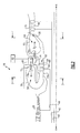
FIGURE 2 shows a close up view of a portion of a combustion section of theFIGURE 1 engine. -
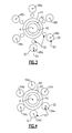
FIGURE 3 shows a simplified sectional view of theFIGURE 1 engine at line 3-3 inFIGURE 2 . -
FIGURE 4 shows a simplified sectional view of theFIGURE 1 engine at line 4-4 inFIGURE 2 . -
FIGURE 5 shows a fuel delivery manifold of theFIGURE 1 engine. - Referring to
Figure 1 , an example turbomachine, such as agas turbine engine 10, is circumferentially disposed about an axis A. Thegas turbine engine 10 includes afan section 12, acompression section 14, a combustion section 16, aturbine section 18, and anexhaust section 20. Other example turbomachines may include more or fewer sections. - In this example, the
fan section 12 includes afirst fan 22 and asecond fan 24. Theexample compression section 14 includes a low-pressure compressor 26 and a high-pressure compressor 28. The example combustion section 16 includes afirst combustor 30 and asecond combustor 32. Also, theexample turbine section 18 includes a high-pressure turbine 34, an intermediate-pressure turbine 36, and low-pressure turbine 38. - The example
gas turbine engine 10 includes afirst spool 40, asecond spool 42, and athird spool 44. Thefirst spool 40 rotatably couples thefirst fan 22 to the low-pressure turbine 38. In this example, a fandrive gear system 46 is used to rotatably link thefirst fan 22 with thefirst spool 40. Thesecond spool 42 rotatably couples thesecond fan 24 and the low-pressure compressor 26 to the intermediate-pressure turbine 36. Thethird spool 44 rotatably couples the high-pressure compressor 28 to the high-pressure turbine 34. - Except where indicated otherwise, the examples described in this disclosure are not limited to the three-spool gas turbine architecture described, and may be used in other architectures, such as a single-spool axial design, a two-spool axial design, and still other architectures. That is, there are various types of gas turbine engines, and other turbomachines, that can benefit from the examples disclosed herein.
- During operation, a flow of air enters the
engine 10 through thefan section 12. The flow of air is compressed in thecompression section 14. The compressed flow is then mixed with fuel and combusted in the combustion section 16. The products of combustion are then expanded to rotate rotors of theturbine section 18. The rotors rotatably drive thefirst fan 22, thesecond fan 24, the low-pressure compressor 26, and the high-pressure compressor 28. Once expanded, flow exits theengine 10 at theexhaust section 20. As can be appreciated, flow generally moves through theengine 10 in a direction F. - Referring to
Figure 2 with continuing reference toFigure 1 , thefirst combustor 30 includes anozzle 48a and afirst combustion chamber 50. During operation, a mixture of fuel and compressed air is injected from thenozzle 48a into thefirst combustion chamber 50. Thenozzle 48a sprays the mixture of fuel and compressed air into thefirst combustion chamber 50 in a first direction D 1. - Flow moves through the
first combustion chamber 50 in the first direction D1, which is opposite the general direction of flow F through theengine 10. The flow includes the products of combustion. In some examples, thefirst combustor 30 is considered a reverse flow combustor because the flow moves through thefirst combustion chamber 50 in a direction opposite the general direction of flow F through theengine 10. - Once combusted, flow moves from the
first combustion chamber 50 through anoutlet conduit 52 to drive the high-pressure turbine 34. Flow moves through theoutlet conduit 52 in a direction opposite the first direction D1. - The
second combustor 32 includes anozzle 54a and asecond combustion chamber 56. During operation, a mixture of fuel and compressed air is injected from thenozzle 54a into thesecond combustion chamber 56 of thesecond combustor 32. Notably, thenozzle 54a sprays the mixture of fuel and compressed air into thesecond combustion chamber 56 in a second direction D2, which is the same as the general direction of flow F through theengine 10. - Flow moves from the
second combustion chamber 56 through anoutlet conduit 58 to drive the intermediate-pressure turbine 36. The flow includes the products of combustion within thesecond combustor 32. As can be appreciated, flow moves through thefirst combustion chamber 50 and thesecond combustion chamber 56 in opposite directions. - In this example, a
single fuel manifold 60 is used to control the flow of fuel to both thenozzle 48a of thefirst combustor 30 and thenozzle 54a of thesecond combustor 32. Thesingle fuel manifold 60 receives fuel from afuel supply 62. Arranging thenozzle 48a to be axially adjacent thenozzle 54a facilitates this communication of fuel from thesingle fuel manifold 60. - A
swirl air conduit 72 swirls and delivers pressurized air from the high-pressure compressor 28 to thecombustor 30. Anotherswirl air conduit 74 swirls and delivers pressurized air from high-pressure compressor 28 and combustor housing to thefuel nozzles 54a. The air delivered by theconduits nozzles - Referring now to
Figures 3-5 with continuing reference toFigure 2 , the examplegas turbine engine 10 includes six of thefirst combustors 30 and six of thesecond combustors 32. Thefirst combustors 30 and thesecond combustors 32 are circumferentially distributed about the axis A. Thefirst combustors 30 are axially in front of thesecond combustors 32 relative to the direction of flow F through theengine 10. - In this example, the
single fuel manifold 60 delivers fuel to all twelve of thecombustors engine 10. Notably, thefuel manifold 60 is a helix that is centered radially about the axis A, and centered axially relative to thefirst combustors 30 and thesecond combustors 32. Theexample fuel manifold 60 is configured to deliver fuel to thefuel nozzles 54a-54f of thesecond combustors 32 prior to thefuel nozzles 48a-48f of thefirst combustors 30. Notably, thefuel manifold 60 shown inFigure 5 has been axially stretched for clarity. - The
fuel manifold 60 includes avalve 70 that can be closed to block fuel flow to thefirst combustors 30. When thevalve 70 is closed, no fuel is combusted infirst combustors 30. When no fuel is combusted in thefirst combustors 30, the high-pressure turbine 34 windmills, which causes the high-pressure compressor 28 to rotate at an insufficient speed to generate a significant increase in the temperature or pressure of the air. In one example, thevalve 70 is closed when the engine 10 (Figure 1 ) is propelling an aircraft during takeoff on a hot day. In another example, thevalve 70 is opened when theengine 10 is propelling an aircraft during cruise. Opening thevalve 70 delivers fuel to thefirst combustors 30, which drive the high-pressure turbine 34 to maximize the compression pressure of high-pressure compressor 28. The power of theengine 10 is thus controlled in part by controlling thefuel supply 62. - In this example, the products of combustion moving through the
outlet conduit 52 drive thethird spool 44, and the products of combustion moving through theoutlet conduit 58 drive thesecond spool 42. The examplefirst combustor 30 and thesecond combustor 32 are thus configured to drive different spools. - The
spools shafts - In some examples, the
nozzles 54a-54f introduce air and uncombusted fuel from theoutlet conduit 52 into thesecond combustion chamber 56. In such examples, thenozzle 54a is able to introduce fuel into thesecond combustion chamber 56 even if thenozzle 54a is not connected to thesingle fuel manifold 60. That is, thefirst combustor 30 may not combust all of the fuel introduced by thenozzles 48a-48f. This fuel is not wasted, because thesecond combustor 32 is able to combust this fuel. - The example rotors in the
turbine section 18 include an array of blades 64 that rotate together with thethird shaft 44 about the axis A. The example high-pressure turbine 34 also includes two axial rows ofvanes 66 that do not rotate. - In this example, the vanes 66a in the first row are adjustable vanes. That is, the vanes 66a can be pivoted, or otherwise actuated, to control flow through the high-
pressure turbine 34. Controlling flow through the high-pressure turbine 34 regulates rotation of the high-pressure compressor 28, which is rotatably coupled to the high-pressure turbine 34. In this example, the vanes 66a are pivoted about a radially extending axis. Other examples include other ways of manipulating the vanes 66a to control flow through the high-pressure turbine 34. - A person having skill in this art and the benefit of this disclosure would understand how to vary the position of the
vanes 66 and 66a to control flow through the high-pressure turbine 34. United States Published Application No.20090016871 , which is incorporated herein by reference, discloses an example configuration having variable vanes that control flow through a gas turbine engine. Other examples configurations of variable vanes could be used. - Although only the high-
pressure turbine 34 is described as having variable vanes 66a, the intermediate-pressure turbine 36 and the low-pressure turbine 38 could also include variable vanes. That is, any area of theturbine section 18 could include variable vanes to control flow through a desired area of theturbine section 18. Also, the blades 64 inturbine section 18, or other components, could be varied to control flow through a desired area of theturbine section 18. - The
example engine 10 may include a clutch 68. The low-pressure compressor 26 and the high-pressure compressor 28 are selectively coupled in rotation together via the clutch 68. In some examples, coupling the low-pressure compressor 26 together with the high-pressure compressor 28 slows the rotational speed of the low-pressure compressor 26 to desirably reduce the pressure ratio of the high-pressure compressor 28. - Features of some of the disclosed examples include a back-to-back arrangement of the first combustor and the second combustor, which decreases the axial length of the engine over other designs. The back-to-back arrangement also enables a delivering fuel to the combustors using a single fuel manifold. Another feature of some of the disclosed examples includes the variable turbines, which can act as chokepoint for flow through the engine.
- The preceding description is exemplary rather than limiting in nature. Variations and modifications to the disclosed examples may become apparent to those skilled in the art that do not necessarily depart from the essence of this disclosure. Thus, the scope of legal protection given to this disclosure can only be determined by studying the following claims.
Claims (15)
- A turbomachine assembly, comprising:a first combustor (30) configured to combust fuel and compressed air; anda second combustor (32) configured to combust fuel and compressed air, wherein flow moves through the first combustor (30) in a first direction and flow moves though the second combustor (32) in a second direction different than the first direction, the first combustor (30) axially spaced from the second combustor (32).
- The turbomachine assembly of claim 1, wherein products of combustion from the first combustor (30) are expanded to drive a first spool (44), and products of combustion from the second combustor (32) are expanded to drive a second spool (42) different than the first spool (44).
- The turbomachine assembly of claim 1 or 2, wherein the first direction is opposite a general direction of flow through the turbomachine, the general direction of flow extending from a fan section (12) of the turbomachine to an exhaust section (20) of the turbomachine.
- The turbomachine assembly of any preceding claim, wherein the first combustor (30) comprises a plurality of reverse flow combustors (30) annularly distributed about an axis of the turbomachine.
- The turbomachine assembly of any preceding claim, wherein a compressor (28) directly provides compressed air to the first combustor (30), and a turbine section (34) directly provides compressed air to the second combustor (32).
- The turbomachine assembly of claim 5, wherein the turbine section (34) includes variable vanes (66a).
- A turbomachine assembly, comprising:a compressor section (14);a first combustor section (30) that receives a flow of compressed fluid from the compressor section (14);a first turbine section (34) that receives a product of combustion from the first combustor section (30);a second combustor section (32) that receives a flow of compressed fluid from the first turbine section (34); anda second turbine section (36) that receives a product of combustion from the second combustor section (32), wherein flow moves through the first combustor (30) in a first direction and flow moves though the second combustor (32) in a second direction different than the first direction.
- The turbomachine assembly of claim 7, wherein the first turbine section (34) is a higher pressure turbine than the second turbine section (36).
- The turbomachine assembly of claim 7 or 8, wherein the first turbine section (34) drives a first spool (44), and the second turbine section (36) drives a second spool (42) different than the first spool (44).
- The turbomachine assembly of claim 2 or 9, wherein the first spool (44) is rotatably coupled to a high-pressure compressor (28) of the compressor section, and the second spool (42) is rotatably coupled to a low-pressure compressor (26) of the compressor section (14), the assembly optionally further, including a third turbine section (38) that is rotatably coupled to a fan with a third spool (40).
- The turbomachine assembly of any preceding claim, including a (common) manifold (60) configured to supply fuel to both the first combustor (30) and the second combustor (32).
- The turbomachine assembly of any preceding claim, wherein the first direction is opposite the second direction.
- The turbomachine assembly of any preceding claim, wherein the turbomachine is a gas turbine engine (10).
- A method of operating a turbomachine, comprising:moving a mixture of fuel and compressed air through a first combustor section (30) in a first direction; andmoving a mixture of fuel and compressed air through a second combustor section in a second (32) direction different than the first direction.
- The method of claim 14, comprising one or more of:communicating products of combustion from the first combustor section (30) to a turbine section (34) and communicating compressed air from the turbine section (34) to the second combustor section (32);communicating fuel to the first combustor section (30) and the second combustor section (32) using a common manifold (60); anddriving a first turbine section (34) with the first combustor section (30) and driving a second turbine section (36) with the second combustor section (32), the first turbine section (34) and the second turbine section (36) configured to drive different spools (44,42).
Applications Claiming Priority (1)
| Application Number | Priority Date | Filing Date | Title |
|---|---|---|---|
| US13/153,550 US20120304660A1 (en) | 2011-06-06 | 2011-06-06 | Turbomachine combustors having different flow paths |
Publications (2)
| Publication Number | Publication Date |
|---|---|
| EP2532857A1 true EP2532857A1 (en) | 2012-12-12 |
| EP2532857B1 EP2532857B1 (en) | 2016-02-10 |
Family
ID=46146732
Family Applications (1)
| Application Number | Title | Priority Date | Filing Date |
|---|---|---|---|
| EP12168699.2A Not-in-force EP2532857B1 (en) | 2011-06-06 | 2012-05-21 | Turbomachine assembly with combustors having different flow directions and corresponding operating method |
Country Status (2)
| Country | Link |
|---|---|
| US (1) | US20120304660A1 (en) |
| EP (1) | EP2532857B1 (en) |
Cited By (4)
| Publication number | Priority date | Publication date | Assignee | Title |
|---|---|---|---|---|
| WO2014152875A1 (en) | 2013-03-14 | 2014-09-25 | United Technologies Corporation | Gas turbine engine architecture with nested concentric combustor |
| CN109826706A (en) * | 2019-01-24 | 2019-05-31 | 四川旭虹光电科技有限公司 | A kind of pair of oxygen-containing gas carries out the device of heating pressurized treatment |
| US11156164B2 (en) | 2019-05-21 | 2021-10-26 | General Electric Company | System and method for high frequency accoustic dampers with caps |
| US11174792B2 (en) | 2019-05-21 | 2021-11-16 | General Electric Company | System and method for high frequency acoustic dampers with baffles |
Families Citing this family (8)
| Publication number | Priority date | Publication date | Assignee | Title |
|---|---|---|---|---|
| US9957832B2 (en) * | 2012-02-28 | 2018-05-01 | United Technologies Corporation | Variable area turbine |
| US9222409B2 (en) * | 2012-03-15 | 2015-12-29 | United Technologies Corporation | Aerospace engine with augmenting turbojet |
| US20160047304A1 (en) * | 2013-12-19 | 2016-02-18 | United Technologies Corporation | Ultra high overall pressure ratio gas turbine engine |
| US20150176530A1 (en) * | 2013-12-19 | 2015-06-25 | United Technologies Corporation | Ultra high overall pessure ratio gas turbine engine |
| GB201406386D0 (en) * | 2014-04-09 | 2014-05-21 | Rolls Royce Plc | Gas turbine engine |
| GB201510167D0 (en) * | 2015-06-11 | 2015-07-29 | Rolls Royce Plc | Gas turbine engine |
| EP3438530B1 (en) * | 2017-07-31 | 2020-03-04 | Ansaldo Energia Switzerland AG | Sequential combustor assembly for a gas turbine assembly |
| US11859539B2 (en) * | 2021-02-01 | 2024-01-02 | General Electric Company | Aircraft propulsion system with inter-turbine burner |
Citations (5)
| Publication number | Priority date | Publication date | Assignee | Title |
|---|---|---|---|---|
| GB814380A (en) * | 1954-11-10 | 1959-06-03 | Power Jets Res & Dev Ltd | Power plant incorporating a dynamic compressor |
| GB2010407A (en) * | 1977-12-01 | 1979-06-27 | United Technologies Corp | Burner for gas turbine engine |
| EP0276397A1 (en) * | 1986-12-09 | 1988-08-03 | BBC Brown Boveri AG | Gas turbine combustor |
| EP0501877A1 (en) * | 1991-02-28 | 1992-09-02 | Societe Nationale D'etude Et De Construction De Moteurs D'aviation "Snecma" | Combustion chamber with lean premix and counterflow chamber for stabilisation of the premix flame |
| US20090016871A1 (en) | 2007-07-10 | 2009-01-15 | United Technologies Corp. | Systems and Methods Involving Variable Vanes |
-
2011
- 2011-06-06 US US13/153,550 patent/US20120304660A1/en not_active Abandoned
-
2012
- 2012-05-21 EP EP12168699.2A patent/EP2532857B1/en not_active Not-in-force
Patent Citations (5)
| Publication number | Priority date | Publication date | Assignee | Title |
|---|---|---|---|---|
| GB814380A (en) * | 1954-11-10 | 1959-06-03 | Power Jets Res & Dev Ltd | Power plant incorporating a dynamic compressor |
| GB2010407A (en) * | 1977-12-01 | 1979-06-27 | United Technologies Corp | Burner for gas turbine engine |
| EP0276397A1 (en) * | 1986-12-09 | 1988-08-03 | BBC Brown Boveri AG | Gas turbine combustor |
| EP0501877A1 (en) * | 1991-02-28 | 1992-09-02 | Societe Nationale D'etude Et De Construction De Moteurs D'aviation "Snecma" | Combustion chamber with lean premix and counterflow chamber for stabilisation of the premix flame |
| US20090016871A1 (en) | 2007-07-10 | 2009-01-15 | United Technologies Corp. | Systems and Methods Involving Variable Vanes |
Cited By (5)
| Publication number | Priority date | Publication date | Assignee | Title |
|---|---|---|---|---|
| WO2014152875A1 (en) | 2013-03-14 | 2014-09-25 | United Technologies Corporation | Gas turbine engine architecture with nested concentric combustor |
| EP2971649A4 (en) * | 2013-03-14 | 2016-03-16 | United Technologies Corp | GAS TURBINE ENGINE ARCHITECTURE HAVING CONCENTRIC NITROGEN COMBUSTION CHAMBERS |
| CN109826706A (en) * | 2019-01-24 | 2019-05-31 | 四川旭虹光电科技有限公司 | A kind of pair of oxygen-containing gas carries out the device of heating pressurized treatment |
| US11156164B2 (en) | 2019-05-21 | 2021-10-26 | General Electric Company | System and method for high frequency accoustic dampers with caps |
| US11174792B2 (en) | 2019-05-21 | 2021-11-16 | General Electric Company | System and method for high frequency acoustic dampers with baffles |
Also Published As
| Publication number | Publication date |
|---|---|
| EP2532857B1 (en) | 2016-02-10 |
| US20120304660A1 (en) | 2012-12-06 |
Similar Documents
| Publication | Publication Date | Title |
|---|---|---|
| EP2532857B1 (en) | Turbomachine assembly with combustors having different flow directions and corresponding operating method | |
| US11215121B2 (en) | Fuel spray nozzle | |
| US11236675B2 (en) | Gas turbine engine with intercooled cooling air and turbine drive | |
| EP3239478B1 (en) | Combined drive for cooling air using cooling compressor and aircraft air supply pump | |
| EP3181868B1 (en) | Control cooling air by heat exchanger bypass | |
| JP5121440B2 (en) | Convertible gas turbine engine | |
| US9726113B2 (en) | Turbine engine assembly and methods of assembling same | |
| US11781490B2 (en) | Operability geared turbofan engine including compressor section variable guide vanes | |
| EP3431738B1 (en) | Tangential drive for gas turbine engine accessories | |
| US8365514B1 (en) | Hybrid turbofan engine | |
| US20120131902A1 (en) | Aft fan adaptive cycle engine | |
| EP3330517B1 (en) | Gas turbine engine with intercooled cooling air and controlled boost compressor | |
| EP3096023B1 (en) | Gas turbine with compressor blade tip injector | |
| US20150330301A1 (en) | Gas turbine engine with variable speed turbines | |
| EP3219959B1 (en) | Intercooled cooling air using existing heat exchanger | |
| EP2497904B1 (en) | Gas turbine engine rotor cooling with swirled cooling air | |
| US20250354520A1 (en) | Fuel injector manifold for a turbine engine | |
| EP2959132B1 (en) | Self-purging fuel injector system for a gas turbine engine | |
| US9964033B2 (en) | Two-spool design for a turboshaft engine with a high-pressure compressor connected to a low-pressure turbine | |
| US20230028552A1 (en) | Gas turbine engine with idle thrust ratio | |
| EP3109436B1 (en) | Gas turbine engine with intercooled cooling air with improved air flow | |
| US12516668B2 (en) | Gear pump assembly | |
| EP4417795A1 (en) | Gas turbine engine with bleed diffuser baffles |
Legal Events
| Date | Code | Title | Description |
|---|---|---|---|
| PUAI | Public reference made under article 153(3) epc to a published international application that has entered the european phase |
Free format text: ORIGINAL CODE: 0009012 |
|
| AK | Designated contracting states |
Kind code of ref document: A1 Designated state(s): AL AT BE BG CH CY CZ DE DK EE ES FI FR GB GR HR HU IE IS IT LI LT LU LV MC MK MT NL NO PL PT RO RS SE SI SK SM TR |
|
| AX | Request for extension of the european patent |
Extension state: BA ME |
|
| 17P | Request for examination filed |
Effective date: 20130610 |
|
| RBV | Designated contracting states (corrected) |
Designated state(s): AL AT BE BG CH CY CZ DE DK EE ES FI FR GB GR HR HU IE IS IT LI LT LU LV MC MK MT NL NO PL PT RO RS SE SI SK SM TR |
|
| GRAP | Despatch of communication of intention to grant a patent |
Free format text: ORIGINAL CODE: EPIDOSNIGR1 |
|
| RIC1 | Information provided on ipc code assigned before grant |
Ipc: F23R 3/34 20060101ALI20150828BHEP Ipc: F02C 3/14 20060101AFI20150828BHEP Ipc: F23R 3/54 20060101ALI20150828BHEP |
|
| INTG | Intention to grant announced |
Effective date: 20150917 |
|
| GRAS | Grant fee paid |
Free format text: ORIGINAL CODE: EPIDOSNIGR3 |
|
| GRAA | (expected) grant |
Free format text: ORIGINAL CODE: 0009210 |
|
| AK | Designated contracting states |
Kind code of ref document: B1 Designated state(s): AL AT BE BG CH CY CZ DE DK EE ES FI FR GB GR HR HU IE IS IT LI LT LU LV MC MK MT NL NO PL PT RO RS SE SI SK SM TR |
|
| REG | Reference to a national code |
Ref country code: GB Ref legal event code: FG4D |
|
| REG | Reference to a national code |
Ref country code: AT Ref legal event code: REF Ref document number: 774775 Country of ref document: AT Kind code of ref document: T Effective date: 20160215 Ref country code: CH Ref legal event code: EP |
|
| REG | Reference to a national code |
Ref country code: IE Ref legal event code: FG4D |
|
| REG | Reference to a national code |
Ref country code: DE Ref legal event code: R096 Ref document number: 602012014619 Country of ref document: DE |
|
| REG | Reference to a national code |
Ref country code: LT Ref legal event code: MG4D |
|
| REG | Reference to a national code |
Ref country code: NL Ref legal event code: MP Effective date: 20160210 |
|
| REG | Reference to a national code |
Ref country code: AT Ref legal event code: MK05 Ref document number: 774775 Country of ref document: AT Kind code of ref document: T Effective date: 20160210 |
|
| PG25 | Lapsed in a contracting state [announced via postgrant information from national office to epo] |
Ref country code: IT Free format text: LAPSE BECAUSE OF FAILURE TO SUBMIT A TRANSLATION OF THE DESCRIPTION OR TO PAY THE FEE WITHIN THE PRESCRIBED TIME-LIMIT Effective date: 20160210 Ref country code: ES Free format text: LAPSE BECAUSE OF FAILURE TO SUBMIT A TRANSLATION OF THE DESCRIPTION OR TO PAY THE FEE WITHIN THE PRESCRIBED TIME-LIMIT Effective date: 20160210 Ref country code: HR Free format text: LAPSE BECAUSE OF FAILURE TO SUBMIT A TRANSLATION OF THE DESCRIPTION OR TO PAY THE FEE WITHIN THE PRESCRIBED TIME-LIMIT Effective date: 20160210 Ref country code: FI Free format text: LAPSE BECAUSE OF FAILURE TO SUBMIT A TRANSLATION OF THE DESCRIPTION OR TO PAY THE FEE WITHIN THE PRESCRIBED TIME-LIMIT Effective date: 20160210 Ref country code: GR Free format text: LAPSE BECAUSE OF FAILURE TO SUBMIT A TRANSLATION OF THE DESCRIPTION OR TO PAY THE FEE WITHIN THE PRESCRIBED TIME-LIMIT Effective date: 20160511 Ref country code: NO Free format text: LAPSE BECAUSE OF FAILURE TO SUBMIT A TRANSLATION OF THE DESCRIPTION OR TO PAY THE FEE WITHIN THE PRESCRIBED TIME-LIMIT Effective date: 20160510 |
|
| PG25 | Lapsed in a contracting state [announced via postgrant information from national office to epo] |
Ref country code: AT Free format text: LAPSE BECAUSE OF FAILURE TO SUBMIT A TRANSLATION OF THE DESCRIPTION OR TO PAY THE FEE WITHIN THE PRESCRIBED TIME-LIMIT Effective date: 20160210 Ref country code: NL Free format text: LAPSE BECAUSE OF FAILURE TO SUBMIT A TRANSLATION OF THE DESCRIPTION OR TO PAY THE FEE WITHIN THE PRESCRIBED TIME-LIMIT Effective date: 20160210 Ref country code: SE Free format text: LAPSE BECAUSE OF FAILURE TO SUBMIT A TRANSLATION OF THE DESCRIPTION OR TO PAY THE FEE WITHIN THE PRESCRIBED TIME-LIMIT Effective date: 20160210 Ref country code: RS Free format text: LAPSE BECAUSE OF FAILURE TO SUBMIT A TRANSLATION OF THE DESCRIPTION OR TO PAY THE FEE WITHIN THE PRESCRIBED TIME-LIMIT Effective date: 20160210 Ref country code: PL Free format text: LAPSE BECAUSE OF FAILURE TO SUBMIT A TRANSLATION OF THE DESCRIPTION OR TO PAY THE FEE WITHIN THE PRESCRIBED TIME-LIMIT Effective date: 20160210 Ref country code: BE Free format text: LAPSE BECAUSE OF NON-PAYMENT OF DUE FEES Effective date: 20160531 Ref country code: LV Free format text: LAPSE BECAUSE OF FAILURE TO SUBMIT A TRANSLATION OF THE DESCRIPTION OR TO PAY THE FEE WITHIN THE PRESCRIBED TIME-LIMIT Effective date: 20160210 Ref country code: LT Free format text: LAPSE BECAUSE OF FAILURE TO SUBMIT A TRANSLATION OF THE DESCRIPTION OR TO PAY THE FEE WITHIN THE PRESCRIBED TIME-LIMIT Effective date: 20160210 Ref country code: IS Free format text: LAPSE BECAUSE OF FAILURE TO SUBMIT A TRANSLATION OF THE DESCRIPTION OR TO PAY THE FEE WITHIN THE PRESCRIBED TIME-LIMIT Effective date: 20160610 Ref country code: PT Free format text: LAPSE BECAUSE OF FAILURE TO SUBMIT A TRANSLATION OF THE DESCRIPTION OR TO PAY THE FEE WITHIN THE PRESCRIBED TIME-LIMIT Effective date: 20160613 |
|
| REG | Reference to a national code |
Ref country code: CH Ref legal event code: PCOW Free format text: NEW ADDRESS: 10 FARM SPRINGS RD., FARMINGTON, CT 06032 (US) |
|
| RAP2 | Party data changed (patent owner data changed or rights of a patent transferred) |
Owner name: UNITED TECHNOLOGIES CORPORATION |
|
| REG | Reference to a national code |
Ref country code: FR Ref legal event code: PLFP Year of fee payment: 5 |
|
| PG25 | Lapsed in a contracting state [announced via postgrant information from national office to epo] |
Ref country code: DK Free format text: LAPSE BECAUSE OF FAILURE TO SUBMIT A TRANSLATION OF THE DESCRIPTION OR TO PAY THE FEE WITHIN THE PRESCRIBED TIME-LIMIT Effective date: 20160210 Ref country code: EE Free format text: LAPSE BECAUSE OF FAILURE TO SUBMIT A TRANSLATION OF THE DESCRIPTION OR TO PAY THE FEE WITHIN THE PRESCRIBED TIME-LIMIT Effective date: 20160210 |
|
| REG | Reference to a national code |
Ref country code: DE Ref legal event code: R097 Ref document number: 602012014619 Country of ref document: DE |
|
| PG25 | Lapsed in a contracting state [announced via postgrant information from national office to epo] |
Ref country code: SM Free format text: LAPSE BECAUSE OF FAILURE TO SUBMIT A TRANSLATION OF THE DESCRIPTION OR TO PAY THE FEE WITHIN THE PRESCRIBED TIME-LIMIT Effective date: 20160210 Ref country code: CZ Free format text: LAPSE BECAUSE OF FAILURE TO SUBMIT A TRANSLATION OF THE DESCRIPTION OR TO PAY THE FEE WITHIN THE PRESCRIBED TIME-LIMIT Effective date: 20160210 Ref country code: RO Free format text: LAPSE BECAUSE OF FAILURE TO SUBMIT A TRANSLATION OF THE DESCRIPTION OR TO PAY THE FEE WITHIN THE PRESCRIBED TIME-LIMIT Effective date: 20160210 Ref country code: SK Free format text: LAPSE BECAUSE OF FAILURE TO SUBMIT A TRANSLATION OF THE DESCRIPTION OR TO PAY THE FEE WITHIN THE PRESCRIBED TIME-LIMIT Effective date: 20160210 |
|
| PLBE | No opposition filed within time limit |
Free format text: ORIGINAL CODE: 0009261 |
|
| STAA | Information on the status of an ep patent application or granted ep patent |
Free format text: STATUS: NO OPPOSITION FILED WITHIN TIME LIMIT |
|
| PG25 | Lapsed in a contracting state [announced via postgrant information from national office to epo] |
Ref country code: BE Free format text: LAPSE BECAUSE OF FAILURE TO SUBMIT A TRANSLATION OF THE DESCRIPTION OR TO PAY THE FEE WITHIN THE PRESCRIBED TIME-LIMIT Effective date: 20160210 Ref country code: LU Free format text: LAPSE BECAUSE OF FAILURE TO SUBMIT A TRANSLATION OF THE DESCRIPTION OR TO PAY THE FEE WITHIN THE PRESCRIBED TIME-LIMIT Effective date: 20160521 |
|
| REG | Reference to a national code |
Ref country code: CH Ref legal event code: PL |
|
| 26N | No opposition filed |
Effective date: 20161111 |
|
| PG25 | Lapsed in a contracting state [announced via postgrant information from national office to epo] |
Ref country code: LI Free format text: LAPSE BECAUSE OF NON-PAYMENT OF DUE FEES Effective date: 20160531 Ref country code: CH Free format text: LAPSE BECAUSE OF NON-PAYMENT OF DUE FEES Effective date: 20160531 |
|
| REG | Reference to a national code |
Ref country code: IE Ref legal event code: MM4A |
|
| PG25 | Lapsed in a contracting state [announced via postgrant information from national office to epo] |
Ref country code: SI Free format text: LAPSE BECAUSE OF FAILURE TO SUBMIT A TRANSLATION OF THE DESCRIPTION OR TO PAY THE FEE WITHIN THE PRESCRIBED TIME-LIMIT Effective date: 20160210 Ref country code: BG Free format text: LAPSE BECAUSE OF FAILURE TO SUBMIT A TRANSLATION OF THE DESCRIPTION OR TO PAY THE FEE WITHIN THE PRESCRIBED TIME-LIMIT Effective date: 20160510 |
|
| REG | Reference to a national code |
Ref country code: FR Ref legal event code: PLFP Year of fee payment: 6 |
|
| PG25 | Lapsed in a contracting state [announced via postgrant information from national office to epo] |
Ref country code: IE Free format text: LAPSE BECAUSE OF NON-PAYMENT OF DUE FEES Effective date: 20160521 |
|
| REG | Reference to a national code |
Ref country code: DE Ref legal event code: R082 Ref document number: 602012014619 Country of ref document: DE Representative=s name: SCHMITT-NILSON SCHRAUD WAIBEL WOHLFROM PATENTA, DE |
|
| REG | Reference to a national code |
Ref country code: DE Ref legal event code: R082 Ref document number: 602012014619 Country of ref document: DE Representative=s name: SCHMITT-NILSON SCHRAUD WAIBEL WOHLFROM PATENTA, DE Ref country code: DE Ref legal event code: R081 Ref document number: 602012014619 Country of ref document: DE Owner name: UNITED TECHNOLOGIES CORP. (N.D.GES.D. STAATES , US Free format text: FORMER OWNER: UNITED TECHNOLOGIES CORPORATION, HARTFORD, CONN., US |
|
| REG | Reference to a national code |
Ref country code: FR Ref legal event code: PLFP Year of fee payment: 7 |
|
| PG25 | Lapsed in a contracting state [announced via postgrant information from national office to epo] |
Ref country code: HU Free format text: LAPSE BECAUSE OF FAILURE TO SUBMIT A TRANSLATION OF THE DESCRIPTION OR TO PAY THE FEE WITHIN THE PRESCRIBED TIME-LIMIT; INVALID AB INITIO Effective date: 20120521 Ref country code: CY Free format text: LAPSE BECAUSE OF FAILURE TO SUBMIT A TRANSLATION OF THE DESCRIPTION OR TO PAY THE FEE WITHIN THE PRESCRIBED TIME-LIMIT Effective date: 20160210 |
|
| PG25 | Lapsed in a contracting state [announced via postgrant information from national office to epo] |
Ref country code: TR Free format text: LAPSE BECAUSE OF FAILURE TO SUBMIT A TRANSLATION OF THE DESCRIPTION OR TO PAY THE FEE WITHIN THE PRESCRIBED TIME-LIMIT Effective date: 20160210 Ref country code: MC Free format text: LAPSE BECAUSE OF FAILURE TO SUBMIT A TRANSLATION OF THE DESCRIPTION OR TO PAY THE FEE WITHIN THE PRESCRIBED TIME-LIMIT Effective date: 20160210 Ref country code: MK Free format text: LAPSE BECAUSE OF FAILURE TO SUBMIT A TRANSLATION OF THE DESCRIPTION OR TO PAY THE FEE WITHIN THE PRESCRIBED TIME-LIMIT Effective date: 20160210 Ref country code: MT Free format text: LAPSE BECAUSE OF NON-PAYMENT OF DUE FEES Effective date: 20160531 |
|
| PG25 | Lapsed in a contracting state [announced via postgrant information from national office to epo] |
Ref country code: AL Free format text: LAPSE BECAUSE OF FAILURE TO SUBMIT A TRANSLATION OF THE DESCRIPTION OR TO PAY THE FEE WITHIN THE PRESCRIBED TIME-LIMIT Effective date: 20160210 |
|
| REG | Reference to a national code |
Ref country code: DE Ref legal event code: R081 Ref document number: 602012014619 Country of ref document: DE Owner name: RAYTHEON TECHNOLOGIES CORPORATION (N.D.GES.D.S, US Free format text: FORMER OWNER: UNITED TECHNOLOGIES CORP. (N.D.GES.D. STAATES DELAWARE), FARMINGTON, CONN., US |
|
| P01 | Opt-out of the competence of the unified patent court (upc) registered |
Effective date: 20230520 |
|
| PGFP | Annual fee paid to national office [announced via postgrant information from national office to epo] |
Ref country code: GB Payment date: 20240418 Year of fee payment: 13 |
|
| PGFP | Annual fee paid to national office [announced via postgrant information from national office to epo] |
Ref country code: DE Payment date: 20240418 Year of fee payment: 13 |
|
| PGFP | Annual fee paid to national office [announced via postgrant information from national office to epo] |
Ref country code: FR Payment date: 20240418 Year of fee payment: 13 |
|
| REG | Reference to a national code |
Ref country code: DE Ref legal event code: R119 Ref document number: 602012014619 Country of ref document: DE |
|
| GBPC | Gb: european patent ceased through non-payment of renewal fee |
Effective date: 20250521 |
|
| PG25 | Lapsed in a contracting state [announced via postgrant information from national office to epo] |
Ref country code: GB Free format text: LAPSE BECAUSE OF NON-PAYMENT OF DUE FEES Effective date: 20250521 |
|
| PG25 | Lapsed in a contracting state [announced via postgrant information from national office to epo] |
Ref country code: DE Free format text: LAPSE BECAUSE OF NON-PAYMENT OF DUE FEES Effective date: 20251202 |
|
| PG25 | Lapsed in a contracting state [announced via postgrant information from national office to epo] |
Ref country code: FR Free format text: LAPSE BECAUSE OF NON-PAYMENT OF DUE FEES Effective date: 20250531 |