EP2532831A2 - Mehrstufige hydraulische Bohrlochstimulationsanordnung - Google Patents
Mehrstufige hydraulische Bohrlochstimulationsanordnung Download PDFInfo
- Publication number
- EP2532831A2 EP2532831A2 EP12171400A EP12171400A EP2532831A2 EP 2532831 A2 EP2532831 A2 EP 2532831A2 EP 12171400 A EP12171400 A EP 12171400A EP 12171400 A EP12171400 A EP 12171400A EP 2532831 A2 EP2532831 A2 EP 2532831A2
- Authority
- EP
- European Patent Office
- Prior art keywords
- hydraulic
- tool
- application
- assembly
- well
- Prior art date
- Legal status (The legal status is an assumption and is not a legal conclusion. Google has not performed a legal analysis and makes no representation as to the accuracy of the status listed.)
- Granted
Links
Images

Classifications
-
- E—FIXED CONSTRUCTIONS
- E21—EARTH OR ROCK DRILLING; MINING
- E21B—EARTH OR ROCK DRILLING; OBTAINING OIL, GAS, WATER, SOLUBLE OR MELTABLE MATERIALS OR A SLURRY OF MINERALS FROM WELLS
- E21B43/00—Methods or apparatus for obtaining oil, gas, water, soluble or meltable materials or a slurry of minerals from wells
- E21B43/11—Perforators; Permeators
- E21B43/114—Perforators using direct fluid action on the wall to be perforated, e.g. abrasive jets
-
- E—FIXED CONSTRUCTIONS
- E21—EARTH OR ROCK DRILLING; MINING
- E21B—EARTH OR ROCK DRILLING; OBTAINING OIL, GAS, WATER, SOLUBLE OR MELTABLE MATERIALS OR A SLURRY OF MINERALS FROM WELLS
- E21B43/00—Methods or apparatus for obtaining oil, gas, water, soluble or meltable materials or a slurry of minerals from wells
- E21B43/25—Methods for stimulating production
- E21B43/26—Methods for stimulating production by forming crevices or fractures
Definitions
- Embodiments described relate to stimulation operations in downhole production zones of a well. More specifically, multi-stage hydraulic isolating, perforating, clean-out and fracturing tools and techniques are detailed. Such multiple applications may even be performed on a single wellbore tubular trip into the well delivering an embodiment of a hydraulic treatment assembly therefor.
- a variety of well access applications may be performed within the well with a host of different tools or measurement devices.
- providing downhole access to wells of such challenging architecture may require more than simply dropping a wireline into the well with the applicable tool located at the end thereof.
- wellbore tubulars such as coiled tubing are frequently employed to provide access to wells of such challenging architecture.
- Coiled tubing operations are particularly adept at providing access to highly deviated or tortuous wells where gravity alone fails to provide access to all regions of the wells.
- a spool of pipe i.e., a coiled tubing
- This may be achieved by running coiled tubing from the spool and through a gooseneck guide arm and injector which are positioned over the well at the oilfield. In this manner, forces necessary to drive the coiled tubing through the deviated well may be employed, thereby delivering the tool to a desired downhole location.
- stimulation of different well zones may be carried out in the form of perforating and fracturing applications.
- a perforating gun may be suspended at the end of the coiled tubing and employed for forming perforations through the well wall and into the surrounding formation.
- Subsequent hydraulic fracturing applications may be undertaken in order to deliver proppant and further encourage hydrocarbon recovery from the formation via the perforations.
- a hydraulic jetting tool may be substituted for a more conventional perforating gun.
- a hydraulic jetting tool may comprise a solid body tool with jetting ports through sidewalls thereof and a ball seat positioned therebelow.
- a ball may be pumped from surface and landed on the seat, thereby activating hydraulic jetting through the ports.
- Such a tool may be utilized where the nature of the surrounding formation dictates more effective perforating via a jetting tool.
- coiled tubing is outfitted with a perforating tool which is delivered downhole to a target location to form perforations.
- the coiled tubing is then withdrawn from the well and the perforating tool swapped out for a hydraulic fracturing tool which is subsequently delivered to the same target location for follow-on fracing.
- the perforating tool is a hydraulic jetting tool, it may not subsequently be employed for the lower pressure hydraulic fracturing. That is to say, once the ball has landed, it is stably and irreversibly held in place while the tool is downhole, so as to ensure reliable jetting through the ports.
- a method of performing an application in a well is detailed.
- the application takes place through a wellbore tubular which is utilized to deliver an assembly with a ported tool to a target location. Ports of the tool may be opened for a first hydraulic treatment of the location at a first hydraulic setting.
- the tubular is then retained in the well to perform a second hydraulic treatment with the assembly at a second hydraulic setting.
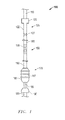
- Fig. 1 is a schematic front view of an embodiment of a multi-stage hydraulic treatment assembly for performing various downhole applications on a single trip into a well.
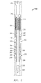
- Fig. 2 is a side cross-sectional schematic view of a hydraulic perforating tool of the treatment assembly of Fig. 1 .
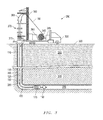
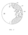
- Fig. 3 is an schematic overview of an oilfield having a well accommodating the treatment assembly of Fig. 1 therein.
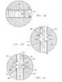
- Fig. 4A is an enlarged depiction of a horizontal section of the well of Fig. 3 having a mechanical packer of the treatment assembly set therein.
- Fig. 4B is an enlarged depiction of a vertical section of the well of Fig. 3 having perforations formed thereat via the perforating tool of the assembly.
- Fig. 4C is an enlarged view of a clean-out application by a fracturing tool of the assembly directed at the perforations of Fig. 4B .
- Fig. 5 is an enlarged view of a perforation taken from 5-5 of Fig. 4C revealing frac-matrix support following a fracturing application with the fracturing tool.
- Fig. 6 is a flow-chart summarizing an embodiment of employing a multi-stage downhole hydraulic treatment assembly.
- Embodiments are described with reference to certain multi-stage downhole hydraulic applications.
- downhole isolating and stimulation applications are described.
- a variety of different downhole hydraulic applications may make use of different embodiments of a hydraulic treatment assembly as detailed herein.
- any number of additional or alternative downhole hydraulic applications such as water jet cutting may also be undertaken.
- embodiments of the downhole assembly employed will include use of a jetting tool capable of forming perforations while also being reversibly actuatable. So, for example, applications with tools uphole and downhole of the jetting tool may also be performed without requiring that the entire assembly first be removed from the well for adjustment of the jetting tool.
- a front view of an embodiment of a multi-stage hydraulic treatment assembly 100 is shown.
- the assembly 100 is configured for performing various downhole applications on a single trip into a well 380 such as that depicted in Fig. 3 .
- the assembly 100 is outfitted with a reversibly actuatable hydraulic jetting tool 150 with nozzles 155 capable of forming perforations 475 as depicted in Fig. 4B .
- the tool 150 may be hydraulically actuated for such an application and effectively deactivated thereafter to allow a hydraulic application through another tool such as the depicted fracturing tool 125.
- the fracturing tool 125 or another tool may also be used in advance of the jetting tool 150.
- the assembly 100 may be constructed with a number of different tools for use in downhole operations. So, for example, in the embodiment shown, a mechanical packer unit 175 is provided downhole of the jetting tool 150. Similarly, the assembly 100 also accommodates the above-noted fracturing tool 125 above the jetting tool 150. Each of the fracturing tool 125, the packer unit 175, and the jetting tool 150 may be used in whatever sequential order called for by downhole operations, for example, as detailed with reference to Figs. 4A-4C herein. That is, concern over actuation of the jetting tool 150 leading to permanent deactivation of other tools, without removal of the assembly 100 from the well 380, is obviated by the reversible nature of the jetting tool 150 (see Fig. 3 ).
- the assembly 100 is shown secured to coiled tubing 110 for downhole conveyance.
- coiled tubing 110 for downhole conveyance.
- alternative forms of hydraulic tubular conveyance, such as jointed pipe, may be utilized.
- zonal isolation may be sought, for example, in advance of stimulation operations.
- the noted mechanical packer unit 175 is provided.
- a bridge plug, slotted liner, or any number of zonal structures may be outfitted at the downhole end of the assembly 100 for deployment.
- a packer 185 with expandable seals 187 is provided along with a setting mechanism 190 which may be hydraulically controlled through the assembly 100.
- the setting mechanism 190 of Fig. 1 is a hydrostatic set module with a hydraulic line 195 to the packer 185 to direct setting thereof. Actuation of the module itself may be directed hydraulically through the interior of a tubular 180 serving as a central mandrel for the entire assembly 100.
- perforating may take place through the jetting tool 150 as alluded to above.
- the tool 150 is outfitted with four nozzles 155 which are vertically offset from one another as with a conventional embodiment.
- alternative orientations or total number of nozzles 155 may also be employed.
- a conventional perforating fluid may be pumped internally through the coiled tubing 110, fracturing tool 125, tubular 180, and eventually out the nozzles 155 to initiate perforating.
- the assembly 100 may be positioned for clean-out and/or fracturing through opened valves 127 in the fracturing tool 125.
- a fluid such as water
- a fluid may be pumped through the interior of the coiled tubing 110, past a hydraulic sub 120 of the fracturing tool 125 and out the opened valves 127 for clean-out of debris.
- the pumping of water in this manner may take place at an increased rate as compared to perforating through the jetting tool 150.
- the larger size orifices of the valves 127 as compared to the jetting nozzles 155 effectively deactivates the jetting tool 150 as described further below.
- a conventional 20/40, 100 mesh fracturing sand, fibers, and other constituents may be added to the fluid at surface, perhaps along with further modification of pump rate. In this manner, a transition from a clean-out application to a fracturing application may be made via the same fracturing tool 125.
- FIG. 2 side cross-sectional view of the hydraulic jetting tool 150 is shown revealing its reversible nature. That is, as opposed to actuation by way of a ball hydraulically delivered to a seal below the jetting nozzles 155, 255, an internal hydraulic mandrel 201 is provided.
- This mandrel 201 is equipped with openings 260, 265 which may be reversibly aligned with the noted nozzles 155, 255 for their actuation and deactivation as the case may be. That is to say, with the openings 260, 265 out of alignment with the nozzles 155, 255, a hydraulic application may take place below the tool 150, as evidenced by the pass through of fluid flow 200.
- Subsequent alignment of the openings 260, 265 with the nozzles 155, 255 may allow for jetting (e.g. perforating) through the nozzles 155, 255. Indeed, subsequent lower pressure hydraulic applications above the tool 150 may take place, even while maintaining the noted alignment. Such is the case with a clean-out or fracturing application through the fracturing tool 125 of Fig. 1 as noted above and detailed further below.
- a fluid flow 200 is shown passing through the entire tool 150 without actuation of the nozzles 155, 255.
- a hydraulically responsive orifice head 210 is provided which is biasingly coupled to the noted mandrel 201 as governed through a spring 220.
- the orifice head 210 and spring 220 may be configured for shifting of the mandrel 201 upon introduction of a given flow rate. So, for example, where a flow rate of less than about 2 barrels per minute (BPM) is pumped through the tool 150, the mandrel 201 may be left in the nozzle closed alignment as shown. However, when a flow rate exceeding 2 BPM is introduced, the head 210 and spring 220 may move downhole, shifting the mandrel 201 into nozzle open alignment as described below.
- BPM barrels per minute
- a nozzle open alignment of the mandrel openings 260, 265 with the nozzles 155, 255 takes place as the mandrel 201 shifts downhole. More specifically, as the mandrel 201 shifts downhole, the uphole openings 260 of the mandrel 201 are moved into alignment with an uphole chamber 272 defined by uphole seals 282, 284. This chamber 272 in turn, is in fluid communication with the uphole nozzles 155, thereby allowing for jet perforating therethrough. Similarly, the downhole openings 265 are simultaneously moved from alignment with an isolated central chamber 274 and into alignment with a downhole chamber 276 defined by downhole seals 286, 288. Thus, with the downhole chamber 276 in fluid communication with the downhole nozzles 255, jet perforating may also take place therethrough.
- the central chamber 274 defined by both uphole 284 and downhole 286 seals, is provided so that while in the nozzle closed position, the downhole openings 265 remain sealed off from possible communication with the downhole nozzles 255.
- the flow 200 is allowed to pass through the tool 150 and a blank orifice 290 thereof, perhaps to hydraulically direct further downhole applications.
- higher flow rate applications above and below the tool 150 may nevertheless take place.
- lower pressure applications such as a 5-6 BPM clean-out, or perhaps packer setting or other applications may take place. That is, due to lower pressures involved, no more than minimal fluid leakage would take place through the nozzles 155, 255 without affect on the higher flow rate applications.
- FIG. 3 an overview of an oilfield 300 is depicted with a well 380 accommodating the overall treatment assembly 100 of Fig. 1 therein.
- the well 380 traverses various formation layers 390, 395 and is outfitted with a casing 385 throughout, even into a lateral leg region.
- this region may remain open-hole in nature.
- coiled tubing 110 is employed for conveyance of the assembly 100 through the well 380, including positioning of a mechanical packer 175 within the noted lateral leg region.
- the setting mechanism 190 may ultimately be employed to direct isolation of this region with the packer 175 (see also Fig. 4A ).
- further downhole activity such as clean-out below the packer 175 by way of the assembly 100 may precede packer setting.
- the assembly 100 includes tubular structure 180 for joining the packer 175 to the jetting tool 150. Indeed, a detachable coupling 380 is shown disposed therebetween.
- the tool 150 and the remainder of the assembly 100 may be detached from the set packer 175 and utilized elsewhere in the well 380.
- perforating via the jetting tool 150 is to take place immediately above the packer 175 and into the lower formation layer 395 as described above.
- other formation locations may also be targeted.
- Subsequent clean-out, fracturing or other stimulation applications may take place through the fracturing tool 125, with fluid, debris and other material produced through a production line 375 at surface.
- a host of surface equipment 350 is provided for directing and driving the use of the entire treatment assembly 100.
- a mobile coiled tubing truck 330 is delivered to the well site accommodating a coiled tubing reel 340 along with a control unit 355 for directing the deployment of the assembly 100 as well as hydraulic applications therethrough.
- a pump 345 is also provided for maintaining flow through the coiled tubing 110 as well as for introducing application specific constituents such as proppant, fibers and/or sand as needed.
- the truck 330 is outfitted with a mobile rig 360 which accommodates a conventional gooseneck injector 365.
- the injector 365 is configured for driving the coiled tubing 110 and assembly 100 through valve and pressure control equipment 370, often referred to as a "Christmas tree".
- valve and pressure control equipment 370 often referred to as a "Christmas tree”.
- positioning is provided for the carrying out of downhole hydraulic applications as detailed further below.
- separate multi-stage operations may proceed without the need to remove and adjust the assembly 100, particularly the jetting tool 150 between different hydraulic applications.
- FIG. 4A reveals the setting of the mechanical packer 175 in the horizontal region of the well 380. This is followed by the perforating of the well 380 in a vertical region with the jetting tool 150 as depicted in Fig. 4B . Subsequently, a clean-out of the perforations 475 may be performed by the fracturing tool 125 as depicted in Fig. 4C .
- additional stimulation through the fracturing tool 125 is also possible, such as acidizing or actual fracturing (see the frac-matrix support 500, evident in Fig. 5 ).
- FIG. 4A an enlarged depiction of a horizontal section of the well 380 is shown with the noted mechanical packer 175 set therein. That is, in contrast to the depiction of Fig. 3 , the seals 187 are fully expanded into engagement with the casing 385 so as to provide isolation below the packer 175. As indicated above, this may be achieved by way of hydraulic actuation of a setting mechanism 190, which in turn sets the packer 175.
- the setting mechanism 190 may be a hydrostatic set module linked to the packer 175 through a hydraulic line 195 to drive the setting.
- the mechanism 190 may be activated through a conventional 'ball drop' or other suitable technique.
- such a nozzle may be employed for clean-out in advance of packer setting. That is, packer setting via the setting mechanism 190 (or perforating through the jetting tool 150 (see Fig. 4B )) may be responsive to certain hydraulic profiles and/or pump rates. However, different hydraulic profiles and/or pump rates may be utilized for clean-outs. So, for example, pump rates outside of a 1-3 BPM rate or so may be utilized for clean-outs, whereas such a 1-3 BPM rate may be utilized for perforating as described above. Meanwhile, a ball-drop technique, sonic profile or other suitable hydraulic actuation means may be utilized for packer setting via the mechanism 190 or other alternative downhole application.
- FIG. 4B an enlarged depiction of a vertical section of the well 380 is shown with the noted perforations 475 formed via the perforating tool 150.
- the perforations 475 may be formed by way of pumping a flow of 1-3 BPM through the tool 150 to actuate the nozzles 155.
- Conventional perforating sand and other material may be pumped along with fluid flow as directed from surface so as to form the perforations 475 through the casing 385 and into the formation 395.
- the effectiveness of the perforating may be enhanced due to the zonal isolation provided by the set packer 175 therebelow (see Fig. 4A ).
- FIG. 4C reveals an enlarged view of a clean-out application by the above detailed fracturing tool 125.
- the tool 125 may be a conventional multi-cycle circulating valve. Regardless, a clean-out takes place, generally at a pump rate of between about 4-7 BPM, debris 480 and other fluid may be flowed uphole and eventually produced through the production line 375 at surface (see Fig. 3 ). Once more, as noted above, this clean-out may be initiated through the fracturing tool 125 following the perforating with the jetting tool 150, without any need for removal of the jetting tool 150 from the well 380.
- FIG. 5 an enlarged view of a perforation 475 is depicted, taken from 5-5 of Fig. 4C .
- frac-matrix support 500 is shown following a fracturing application with the fracturing tool 125 of Fig. 4C . That is, after a clean-out via the tool 125 as noted above, fibers, proppant and other constituents may be added to the flow and/or the flow rate adjusted for fracturing to proceed.
- the end result, represented in the perforation 475 of Fig. 5 may be a matrix support 500 of structure to help hold open and enhance hydrocarbon recovery from the perforation 475 and into the main body of the well 380 for production to surface.
- a flow-chart summarizing an embodiment of employing a multi-stage downhole hydraulic stimulation assembly is depicted.
- the assembly is deployed into the well and an initial actuation may take place such as the hydraulic setting of a mechanical packer (see 620, 640).
- the deployment may take place over coiled tubing, jointed pipe or other appropriate hydraulic tubular conveyance.
- the hydraulic actuation may take place via conventional ball-drop, wireless acoustics or sonic signaling, the particular mode dependent upon the type of setting mechanism utilized.
- the tool may also be a downhole tool other than a mechanical packer, bridge plug or other isolating mechanism.
- a clean-out application as indicated at 680 may take place before, after, or in lieu of the initial actuation of this downhole tool.
- subsequent stages may include the performing of a perforating application via a jetting tool as indicated at 660.
- This perforating may take place at a comparatively high pressure but low BPM flow rate.
- the entire assembly may be maintained in the well as indicated at 680 regardless of the particular next stage hydraulic application to be undertaken (e.g. such as a higher BPM clean-out).
- Embodiments described hereinabove include a downhole treatment and/or stimulation assembly that may be utilized for multi-stage applications in a given well zone without requiring that the assembly be removed between stages of the applications. More specifically, where one stage includes perforating, the assembly need not be removed for adjustment of the perforating tool before or after the perforating. Rather, the application stage to be undertaken before or after the perforating may be undertaken without compromise even in the absence of removal of the perforating tool to surface.
Landscapes
- Geology (AREA)
- Life Sciences & Earth Sciences (AREA)
- Engineering & Computer Science (AREA)
- Mining & Mineral Resources (AREA)
- Environmental & Geological Engineering (AREA)
- Fluid Mechanics (AREA)
- Physics & Mathematics (AREA)
- General Life Sciences & Earth Sciences (AREA)
- Geochemistry & Mineralogy (AREA)
- Consolidation Of Soil By Introduction Of Solidifying Substances Into Soil (AREA)
- Cleaning In General (AREA)
- Earth Drilling (AREA)
- Branch Pipes, Bends, And The Like (AREA)
- Nozzles (AREA)
Applications Claiming Priority (1)
| Application Number | Priority Date | Filing Date | Title |
|---|---|---|---|
| US13/157,978 US9920600B2 (en) | 2011-06-10 | 2011-06-10 | Multi-stage downhole hydraulic stimulation assembly |
Publications (3)
| Publication Number | Publication Date |
|---|---|
| EP2532831A2 true EP2532831A2 (de) | 2012-12-12 |
| EP2532831A3 EP2532831A3 (de) | 2016-09-28 |
| EP2532831B1 EP2532831B1 (de) | 2019-01-23 |
Family
ID=46298261
Family Applications (1)
| Application Number | Title | Priority Date | Filing Date |
|---|---|---|---|
| EP12171400.0A Active EP2532831B1 (de) | 2011-06-10 | 2012-06-08 | Mehrstufige hydraulische Bohrlochstimulationsanordnung |
Country Status (4)
| Country | Link |
|---|---|
| US (1) | US9920600B2 (de) |
| EP (1) | EP2532831B1 (de) |
| CA (1) | CA2779210C (de) |
| DK (1) | DK2532831T3 (de) |
Families Citing this family (8)
| Publication number | Priority date | Publication date | Assignee | Title |
|---|---|---|---|---|
| CN103266876B (zh) * | 2013-02-28 | 2015-11-04 | 中国石油集团川庆钻探工程有限公司长庆井下技术作业公司 | 多级水力喷射分段压裂管柱的压裂工作方法 |
| CN103266875B (zh) * | 2013-02-28 | 2015-12-02 | 中国石油集团川庆钻探工程有限公司长庆井下技术作业公司 | 一种多级水力喷射分段压裂管柱的压裂工作方法 |
| US11015417B2 (en) * | 2014-04-07 | 2021-05-25 | Halliburton Energy Services, Inc. | Using cement slurries in hydrajetting tools |
| GB2551915B (en) | 2015-02-06 | 2021-05-12 | Halliburton Energy Services Inc | Multi-zone fracturing with full wellbore access |
| US10364649B2 (en) | 2015-02-06 | 2019-07-30 | Halliburton Energy Services, Inc. | Multi-zone fracturing with full wellbore access |
| CN105201461A (zh) * | 2015-09-02 | 2015-12-30 | 北京泰坦通源天然气资源技术有限公司 | 连续油管带底封多级喷砂射孔与压裂联作方法 |
| US10450813B2 (en) * | 2017-08-25 | 2019-10-22 | Salavat Anatolyevich Kuzyaev | Hydraulic fraction down-hole system with circulation port and jet pump for removal of residual fracking fluid |
| CN110965978B (zh) * | 2020-01-03 | 2024-07-30 | 中国石油天然气股份有限公司 | 水平井重复压裂工具和水平井重复压裂的工艺方法 |
Family Cites Families (29)
| Publication number | Priority date | Publication date | Assignee | Title |
|---|---|---|---|---|
| GB9513657D0 (en) | 1995-07-05 | 1995-09-06 | Phoenix P A Ltd | Downhole flow control tool |
| US6378612B1 (en) | 1998-03-14 | 2002-04-30 | Andrew Philip Churchill | Pressure actuated downhole tool |
| GB9913370D0 (en) | 1999-06-10 | 1999-08-11 | Nat Oilwell Uk Ltd | A circulating sub apparatus and method |
| GB9916513D0 (en) | 1999-07-15 | 1999-09-15 | Churchill Andrew P | Bypass tool |
| US6607607B2 (en) | 2000-04-28 | 2003-08-19 | Bj Services Company | Coiled tubing wellbore cleanout |
| US7516792B2 (en) * | 2002-09-23 | 2009-04-14 | Exxonmobil Upstream Research Company | Remote intervention logic valving method and apparatus |
| EP1689968A1 (de) | 2003-11-17 | 2006-08-16 | Churchill Drilling Tools Limited | Bohrlochwerkzeug |
| US7311153B2 (en) | 2004-06-18 | 2007-12-25 | Schlumberger Technology Corporation | Flow-biased sequencing valve |
| JP2006106993A (ja) | 2004-10-04 | 2006-04-20 | Hitachi Ltd | ストレージの予約管理方法及びストレージ管理システム |
| US7273099B2 (en) | 2004-12-03 | 2007-09-25 | Halliburton Energy Services, Inc. | Methods of stimulating a subterranean formation comprising multiple production intervals |
| US8066059B2 (en) * | 2005-03-12 | 2011-11-29 | Thru Tubing Solutions, Inc. | Methods and devices for one trip plugging and perforating of oil and gas wells |
| US7267172B2 (en) * | 2005-03-15 | 2007-09-11 | Peak Completion Technologies, Inc. | Cemented open hole selective fracing system |
| US7343975B2 (en) | 2005-09-06 | 2008-03-18 | Halliburton Energy Services, Inc. | Method for stimulating a well |
| US20090056952A1 (en) | 2005-11-24 | 2009-03-05 | Andrew Philip Churchill | Downhole Tool |
| US7497259B2 (en) | 2006-02-01 | 2009-03-03 | Schlumberger Technology Corporation | System and method for forming cavities in a well |
| US7575062B2 (en) * | 2006-06-09 | 2009-08-18 | Halliburton Energy Services, Inc. | Methods and devices for treating multiple-interval well bores |
| US20070284106A1 (en) * | 2006-06-12 | 2007-12-13 | Kalman Mark D | Method and apparatus for well drilling and completion |
| US7673673B2 (en) | 2007-08-03 | 2010-03-09 | Halliburton Energy Services, Inc. | Apparatus for isolating a jet forming aperture in a well bore servicing tool |
| GB0716049D0 (en) | 2007-08-17 | 2007-09-26 | Welltools Ltd | Switchable circulating tool |
| US7849924B2 (en) * | 2007-11-27 | 2010-12-14 | Halliburton Energy Services Inc. | Method and apparatus for moving a high pressure fluid aperture in a well bore servicing tool |
| US20090308588A1 (en) * | 2008-06-16 | 2009-12-17 | Halliburton Energy Services, Inc. | Method and Apparatus for Exposing a Servicing Apparatus to Multiple Formation Zones |
| US8960292B2 (en) * | 2008-08-22 | 2015-02-24 | Halliburton Energy Services, Inc. | High rate stimulation method for deep, large bore completions |
| US7775285B2 (en) * | 2008-11-19 | 2010-08-17 | Halliburton Energy Services, Inc. | Apparatus and method for servicing a wellbore |
| US8312925B2 (en) * | 2009-02-02 | 2012-11-20 | Schlumberger Technology Corporation | Bottom hole assembly for wellbore operations |
| US8944167B2 (en) * | 2009-07-27 | 2015-02-03 | Baker Hughes Incorporated | Multi-zone fracturing completion |
| US8613321B2 (en) * | 2009-07-27 | 2013-12-24 | Baker Hughes Incorporated | Bottom hole assembly with ported completion and methods of fracturing therewith |
| CN101979823A (zh) | 2010-10-14 | 2011-02-23 | 中国石油天然气股份有限公司 | 水力喷射射孔压裂气举排液一体化工艺管柱 |
| US20120199353A1 (en) * | 2011-02-07 | 2012-08-09 | Brent Daniel Fermaniuk | Wellbore injection system |
| US20130180721A1 (en) * | 2011-12-27 | 2013-07-18 | Ncs Oilfield Services Canada Inc. | Downhole Fluid Treatment Tool |
-
2011
- 2011-06-10 US US13/157,978 patent/US9920600B2/en active Active
-
2012
- 2012-06-08 DK DK12171400.0T patent/DK2532831T3/da active
- 2012-06-08 CA CA2779210A patent/CA2779210C/en active Active
- 2012-06-08 EP EP12171400.0A patent/EP2532831B1/de active Active
Non-Patent Citations (1)
| Title |
|---|
| None |
Also Published As
| Publication number | Publication date |
|---|---|
| EP2532831A3 (de) | 2016-09-28 |
| EP2532831B1 (de) | 2019-01-23 |
| US9920600B2 (en) | 2018-03-20 |
| US20120312536A1 (en) | 2012-12-13 |
| CA2779210C (en) | 2020-07-14 |
| CA2779210A1 (en) | 2012-12-10 |
| DK2532831T3 (da) | 2019-05-06 |
Similar Documents
| Publication | Publication Date | Title |
|---|---|---|
| EP2532831B1 (de) | Mehrstufige hydraulische Bohrlochstimulationsanordnung | |
| CA2986438C (en) | Advancement of a tubular string into a wellbore | |
| US7278486B2 (en) | Fracturing method providing simultaneous flow back | |
| EP2126282B1 (de) | Vorrichtung und verfahren zur herstellung eines wasserstrahl-bohrlochs | |
| US9581003B2 (en) | Completing a well in a reservoir | |
| US7681654B1 (en) | Isolating well bore portions for fracturing and the like | |
| US9428988B2 (en) | Hydrocarbon well and technique for perforating casing toe | |
| US20140158357A1 (en) | Nozzle selective perforating jet assembly | |
| US20100212912A1 (en) | Valve | |
| US9133694B2 (en) | Nozzle selective perforating jet assembly | |
| US7857067B2 (en) | Downhole application for a backpressure valve | |
| CA2999197C (en) | Method of well completion | |
| Van Gijtenbeek et al. | Overdisplacing Propped Fracture Treatments-Good Practice or Asking for Trouble?(SPE 154397) | |
| EP2659089B1 (de) | Verfahren und vorrichtung zur durchflussregelung in ein bohrloch | |
| Algadi et al. | Multistage hydraulic fracturing using coiled tubing-activated frac sleeves: Case study from the permian basin | |
| US7213648B2 (en) | Pressure-actuated perforation with continuous removal of debris | |
| DK201470817A1 (en) | Wellbore completion method | |
| US9404350B2 (en) | Flow-activated flow control device and method of using same in wellbores | |
| US20160369603A1 (en) | Redressing method and redressed completion system |
Legal Events
| Date | Code | Title | Description |
|---|---|---|---|
| PUAI | Public reference made under article 153(3) epc to a published international application that has entered the european phase |
Free format text: ORIGINAL CODE: 0009012 |
|
| 17P | Request for examination filed |
Effective date: 20120608 |
|
| AK | Designated contracting states |
Kind code of ref document: A2 Designated state(s): AL AT BE BG CH CY CZ DE DK EE ES FI FR GB GR HR HU IE IS IT LI LT LU LV MC MK MT NL NO PL PT RO RS SE SI SK SM TR |
|
| AX | Request for extension of the european patent |
Extension state: BA ME |
|
| PUAL | Search report despatched |
Free format text: ORIGINAL CODE: 0009013 |
|
| AK | Designated contracting states |
Kind code of ref document: A3 Designated state(s): AL AT BE BG CH CY CZ DE DK EE ES FI FR GB GR HR HU IE IS IT LI LT LU LV MC MK MT NL NO PL PT RO RS SE SI SK SM TR |
|
| AX | Request for extension of the european patent |
Extension state: BA ME |
|
| RIC1 | Information provided on ipc code assigned before grant |
Ipc: E21B 43/26 20060101ALI20160823BHEP Ipc: E21B 43/114 20060101AFI20160823BHEP |
|
| RIN1 | Information on inventor provided before grant (corrected) |
Inventor name: MCCALLUM, BARRY Inventor name: SWAREN, JASON Inventor name: MULLEN, KEVIN Inventor name: MALONE, BRADLEY P. Inventor name: MAUTH, KEVIN DOUGLAS |
|
| RIN1 | Information on inventor provided before grant (corrected) |
Inventor name: SWAREN, JASON Inventor name: MALONE, BRADLEY P. Inventor name: MCCALLUM, BARRY Inventor name: MAUTH, KEVIN DOUGLAS Inventor name: MULLEN, KEVIN |
|
| GRAP | Despatch of communication of intention to grant a patent |
Free format text: ORIGINAL CODE: EPIDOSNIGR1 |
|
| STAA | Information on the status of an ep patent application or granted ep patent |
Free format text: STATUS: GRANT OF PATENT IS INTENDED |
|
| RIC1 | Information provided on ipc code assigned before grant |
Ipc: E21B 43/26 20060101ALI20180417BHEP Ipc: E21B 43/114 20060101AFI20180417BHEP |
|
| INTG | Intention to grant announced |
Effective date: 20180517 |
|
| GRAS | Grant fee paid |
Free format text: ORIGINAL CODE: EPIDOSNIGR3 |
|
| GRAA | (expected) grant |
Free format text: ORIGINAL CODE: 0009210 |
|
| STAA | Information on the status of an ep patent application or granted ep patent |
Free format text: STATUS: THE PATENT HAS BEEN GRANTED |
|
| AK | Designated contracting states |
Kind code of ref document: B1 Designated state(s): AL AT BE BG CH CY CZ DE DK EE ES FI FR GB GR HR HU IE IS IT LI LT LU LV MC MK MT NL NO PL PT RO RS SE SI SK SM TR |
|
| REG | Reference to a national code |
Ref country code: GB Ref legal event code: FG4D |
|
| REG | Reference to a national code |
Ref country code: CH Ref legal event code: EP |
|
| REG | Reference to a national code |
Ref country code: AT Ref legal event code: REF Ref document number: 1091595 Country of ref document: AT Kind code of ref document: T Effective date: 20190215 |
|
| REG | Reference to a national code |
Ref country code: IE Ref legal event code: FG4D |
|
| REG | Reference to a national code |
Ref country code: DE Ref legal event code: R096 Ref document number: 602012056147 Country of ref document: DE |
|
| REG | Reference to a national code |
Ref country code: DK Ref legal event code: T3 Effective date: 20190429 |
|
| REG | Reference to a national code |
Ref country code: NL Ref legal event code: MP Effective date: 20190123 |
|
| PG25 | Lapsed in a contracting state [announced via postgrant information from national office to epo] |
Ref country code: NL Free format text: LAPSE BECAUSE OF FAILURE TO SUBMIT A TRANSLATION OF THE DESCRIPTION OR TO PAY THE FEE WITHIN THE PRESCRIBED TIME-LIMIT Effective date: 20190123 |
|
| REG | Reference to a national code |
Ref country code: NO Ref legal event code: T2 Effective date: 20190123 |
|
| PG25 | Lapsed in a contracting state [announced via postgrant information from national office to epo] |
Ref country code: SE Free format text: LAPSE BECAUSE OF FAILURE TO SUBMIT A TRANSLATION OF THE DESCRIPTION OR TO PAY THE FEE WITHIN THE PRESCRIBED TIME-LIMIT Effective date: 20190123 Ref country code: PL Free format text: LAPSE BECAUSE OF FAILURE TO SUBMIT A TRANSLATION OF THE DESCRIPTION OR TO PAY THE FEE WITHIN THE PRESCRIBED TIME-LIMIT Effective date: 20190123 Ref country code: ES Free format text: LAPSE BECAUSE OF FAILURE TO SUBMIT A TRANSLATION OF THE DESCRIPTION OR TO PAY THE FEE WITHIN THE PRESCRIBED TIME-LIMIT Effective date: 20190123 Ref country code: LT Free format text: LAPSE BECAUSE OF FAILURE TO SUBMIT A TRANSLATION OF THE DESCRIPTION OR TO PAY THE FEE WITHIN THE PRESCRIBED TIME-LIMIT Effective date: 20190123 Ref country code: PT Free format text: LAPSE BECAUSE OF FAILURE TO SUBMIT A TRANSLATION OF THE DESCRIPTION OR TO PAY THE FEE WITHIN THE PRESCRIBED TIME-LIMIT Effective date: 20190523 Ref country code: FI Free format text: LAPSE BECAUSE OF FAILURE TO SUBMIT A TRANSLATION OF THE DESCRIPTION OR TO PAY THE FEE WITHIN THE PRESCRIBED TIME-LIMIT Effective date: 20190123 |
|
| PGFP | Annual fee paid to national office [announced via postgrant information from national office to epo] |
Ref country code: ES Payment date: 20190604 Year of fee payment: 14 |
|
| REG | Reference to a national code |
Ref country code: AT Ref legal event code: MK05 Ref document number: 1091595 Country of ref document: AT Kind code of ref document: T Effective date: 20190123 |
|
| PG25 | Lapsed in a contracting state [announced via postgrant information from national office to epo] |
Ref country code: IS Free format text: LAPSE BECAUSE OF FAILURE TO SUBMIT A TRANSLATION OF THE DESCRIPTION OR TO PAY THE FEE WITHIN THE PRESCRIBED TIME-LIMIT Effective date: 20190523 Ref country code: BG Free format text: LAPSE BECAUSE OF FAILURE TO SUBMIT A TRANSLATION OF THE DESCRIPTION OR TO PAY THE FEE WITHIN THE PRESCRIBED TIME-LIMIT Effective date: 20190423 Ref country code: RS Free format text: LAPSE BECAUSE OF FAILURE TO SUBMIT A TRANSLATION OF THE DESCRIPTION OR TO PAY THE FEE WITHIN THE PRESCRIBED TIME-LIMIT Effective date: 20190123 Ref country code: HR Free format text: LAPSE BECAUSE OF FAILURE TO SUBMIT A TRANSLATION OF THE DESCRIPTION OR TO PAY THE FEE WITHIN THE PRESCRIBED TIME-LIMIT Effective date: 20190123 Ref country code: GR Free format text: LAPSE BECAUSE OF FAILURE TO SUBMIT A TRANSLATION OF THE DESCRIPTION OR TO PAY THE FEE WITHIN THE PRESCRIBED TIME-LIMIT Effective date: 20190424 Ref country code: LV Free format text: LAPSE BECAUSE OF FAILURE TO SUBMIT A TRANSLATION OF THE DESCRIPTION OR TO PAY THE FEE WITHIN THE PRESCRIBED TIME-LIMIT Effective date: 20190123 |
|
| REG | Reference to a national code |
Ref country code: DE Ref legal event code: R097 Ref document number: 602012056147 Country of ref document: DE |
|
| PG25 | Lapsed in a contracting state [announced via postgrant information from national office to epo] |
Ref country code: AL Free format text: LAPSE BECAUSE OF FAILURE TO SUBMIT A TRANSLATION OF THE DESCRIPTION OR TO PAY THE FEE WITHIN THE PRESCRIBED TIME-LIMIT Effective date: 20190123 Ref country code: SK Free format text: LAPSE BECAUSE OF FAILURE TO SUBMIT A TRANSLATION OF THE DESCRIPTION OR TO PAY THE FEE WITHIN THE PRESCRIBED TIME-LIMIT Effective date: 20190123 Ref country code: EE Free format text: LAPSE BECAUSE OF FAILURE TO SUBMIT A TRANSLATION OF THE DESCRIPTION OR TO PAY THE FEE WITHIN THE PRESCRIBED TIME-LIMIT Effective date: 20190123 Ref country code: IT Free format text: LAPSE BECAUSE OF FAILURE TO SUBMIT A TRANSLATION OF THE DESCRIPTION OR TO PAY THE FEE WITHIN THE PRESCRIBED TIME-LIMIT Effective date: 20190123 Ref country code: RO Free format text: LAPSE BECAUSE OF FAILURE TO SUBMIT A TRANSLATION OF THE DESCRIPTION OR TO PAY THE FEE WITHIN THE PRESCRIBED TIME-LIMIT Effective date: 20190123 Ref country code: CZ Free format text: LAPSE BECAUSE OF FAILURE TO SUBMIT A TRANSLATION OF THE DESCRIPTION OR TO PAY THE FEE WITHIN THE PRESCRIBED TIME-LIMIT Effective date: 20190123 |
|
| PG25 | Lapsed in a contracting state [announced via postgrant information from national office to epo] |
Ref country code: SM Free format text: LAPSE BECAUSE OF FAILURE TO SUBMIT A TRANSLATION OF THE DESCRIPTION OR TO PAY THE FEE WITHIN THE PRESCRIBED TIME-LIMIT Effective date: 20190123 |
|
| PLBE | No opposition filed within time limit |
Free format text: ORIGINAL CODE: 0009261 |
|
| STAA | Information on the status of an ep patent application or granted ep patent |
Free format text: STATUS: NO OPPOSITION FILED WITHIN TIME LIMIT |
|
| PG25 | Lapsed in a contracting state [announced via postgrant information from national office to epo] |
Ref country code: AT Free format text: LAPSE BECAUSE OF FAILURE TO SUBMIT A TRANSLATION OF THE DESCRIPTION OR TO PAY THE FEE WITHIN THE PRESCRIBED TIME-LIMIT Effective date: 20190123 |
|
| 26N | No opposition filed |
Effective date: 20191024 |
|
| REG | Reference to a national code |
Ref country code: DE Ref legal event code: R119 Ref document number: 602012056147 Country of ref document: DE |
|
| PG25 | Lapsed in a contracting state [announced via postgrant information from national office to epo] |
Ref country code: MC Free format text: LAPSE BECAUSE OF FAILURE TO SUBMIT A TRANSLATION OF THE DESCRIPTION OR TO PAY THE FEE WITHIN THE PRESCRIBED TIME-LIMIT Effective date: 20190123 |
|
| REG | Reference to a national code |
Ref country code: CH Ref legal event code: PL |
|
| PG25 | Lapsed in a contracting state [announced via postgrant information from national office to epo] |
Ref country code: SI Free format text: LAPSE BECAUSE OF FAILURE TO SUBMIT A TRANSLATION OF THE DESCRIPTION OR TO PAY THE FEE WITHIN THE PRESCRIBED TIME-LIMIT Effective date: 20190123 |
|
| REG | Reference to a national code |
Ref country code: BE Ref legal event code: MM Effective date: 20190630 |
|
| PG25 | Lapsed in a contracting state [announced via postgrant information from national office to epo] |
Ref country code: TR Free format text: LAPSE BECAUSE OF FAILURE TO SUBMIT A TRANSLATION OF THE DESCRIPTION OR TO PAY THE FEE WITHIN THE PRESCRIBED TIME-LIMIT Effective date: 20190123 |
|
| PG25 | Lapsed in a contracting state [announced via postgrant information from national office to epo] |
Ref country code: DE Free format text: LAPSE BECAUSE OF NON-PAYMENT OF DUE FEES Effective date: 20200101 Ref country code: IE Free format text: LAPSE BECAUSE OF NON-PAYMENT OF DUE FEES Effective date: 20190608 |
|
| PG25 | Lapsed in a contracting state [announced via postgrant information from national office to epo] |
Ref country code: CH Free format text: LAPSE BECAUSE OF NON-PAYMENT OF DUE FEES Effective date: 20190630 Ref country code: LU Free format text: LAPSE BECAUSE OF NON-PAYMENT OF DUE FEES Effective date: 20190608 Ref country code: LI Free format text: LAPSE BECAUSE OF NON-PAYMENT OF DUE FEES Effective date: 20190630 Ref country code: BE Free format text: LAPSE BECAUSE OF NON-PAYMENT OF DUE FEES Effective date: 20190630 |
|
| PG25 | Lapsed in a contracting state [announced via postgrant information from national office to epo] |
Ref country code: FR Free format text: LAPSE BECAUSE OF NON-PAYMENT OF DUE FEES Effective date: 20190630 |
|
| REG | Reference to a national code |
Ref country code: DK Ref legal event code: EBP Effective date: 20200630 |
|
| PG25 | Lapsed in a contracting state [announced via postgrant information from national office to epo] |
Ref country code: CY Free format text: LAPSE BECAUSE OF FAILURE TO SUBMIT A TRANSLATION OF THE DESCRIPTION OR TO PAY THE FEE WITHIN THE PRESCRIBED TIME-LIMIT Effective date: 20190123 |
|
| PG25 | Lapsed in a contracting state [announced via postgrant information from national office to epo] |
Ref country code: MT Free format text: LAPSE BECAUSE OF FAILURE TO SUBMIT A TRANSLATION OF THE DESCRIPTION OR TO PAY THE FEE WITHIN THE PRESCRIBED TIME-LIMIT Effective date: 20190123 Ref country code: HU Free format text: LAPSE BECAUSE OF FAILURE TO SUBMIT A TRANSLATION OF THE DESCRIPTION OR TO PAY THE FEE WITHIN THE PRESCRIBED TIME-LIMIT; INVALID AB INITIO Effective date: 20120608 |
|
| PG25 | Lapsed in a contracting state [announced via postgrant information from national office to epo] |
Ref country code: DK Free format text: LAPSE BECAUSE OF NON-PAYMENT OF DUE FEES Effective date: 20200630 |
|
| PG25 | Lapsed in a contracting state [announced via postgrant information from national office to epo] |
Ref country code: MK Free format text: LAPSE BECAUSE OF FAILURE TO SUBMIT A TRANSLATION OF THE DESCRIPTION OR TO PAY THE FEE WITHIN THE PRESCRIBED TIME-LIMIT Effective date: 20190123 |
|
| PGFP | Annual fee paid to national office [announced via postgrant information from national office to epo] |
Ref country code: GB Payment date: 20250401 Year of fee payment: 14 |
|
| PGFP | Annual fee paid to national office [announced via postgrant information from national office to epo] |
Ref country code: NO Payment date: 20250610 Year of fee payment: 14 |