EP2532549A2 - Engine start control device for hybrid vehicle - Google Patents
Engine start control device for hybrid vehicle Download PDFInfo
- Publication number
- EP2532549A2 EP2532549A2 EP12001768A EP12001768A EP2532549A2 EP 2532549 A2 EP2532549 A2 EP 2532549A2 EP 12001768 A EP12001768 A EP 12001768A EP 12001768 A EP12001768 A EP 12001768A EP 2532549 A2 EP2532549 A2 EP 2532549A2
- Authority
- EP
- European Patent Office
- Prior art keywords
- engine start
- motor
- generator
- engine
- travel
- Prior art date
- Legal status (The legal status is an assumption and is not a legal conclusion. Google has not performed a legal analysis and makes no representation as to the accuracy of the status listed.)
- Granted
Links
Images


Classifications
-
- B—PERFORMING OPERATIONS; TRANSPORTING
- B60—VEHICLES IN GENERAL
- B60W—CONJOINT CONTROL OF VEHICLE SUB-UNITS OF DIFFERENT TYPE OR DIFFERENT FUNCTION; CONTROL SYSTEMS SPECIALLY ADAPTED FOR HYBRID VEHICLES; ROAD VEHICLE DRIVE CONTROL SYSTEMS FOR PURPOSES NOT RELATED TO THE CONTROL OF A PARTICULAR SUB-UNIT
- B60W20/00—Control systems specially adapted for hybrid vehicles
-
- B—PERFORMING OPERATIONS; TRANSPORTING
- B60—VEHICLES IN GENERAL
- B60K—ARRANGEMENT OR MOUNTING OF PROPULSION UNITS OR OF TRANSMISSIONS IN VEHICLES; ARRANGEMENT OR MOUNTING OF PLURAL DIVERSE PRIME-MOVERS IN VEHICLES; AUXILIARY DRIVES FOR VEHICLES; INSTRUMENTATION OR DASHBOARDS FOR VEHICLES; ARRANGEMENTS IN CONNECTION WITH COOLING, AIR INTAKE, GAS EXHAUST OR FUEL SUPPLY OF PROPULSION UNITS IN VEHICLES
- B60K6/00—Arrangement or mounting of plural diverse prime-movers for mutual or common propulsion, e.g. hybrid propulsion systems comprising electric motors and internal combustion engines ; Control systems therefor, i.e. systems controlling two or more prime movers, or controlling one of these prime movers and any of the transmission, drive or drive units Informative references: mechanical gearings with secondary electric drive F16H3/72; arrangements for handling mechanical energy structurally associated with the dynamo-electric machine H02K7/00; machines comprising structurally interrelated motor and generator parts H02K51/00; dynamo-electric machines not otherwise provided for in H02K see H02K99/00
- B60K6/20—Arrangement or mounting of plural diverse prime-movers for mutual or common propulsion, e.g. hybrid propulsion systems comprising electric motors and internal combustion engines ; Control systems therefor, i.e. systems controlling two or more prime movers, or controlling one of these prime movers and any of the transmission, drive or drive units Informative references: mechanical gearings with secondary electric drive F16H3/72; arrangements for handling mechanical energy structurally associated with the dynamo-electric machine H02K7/00; machines comprising structurally interrelated motor and generator parts H02K51/00; dynamo-electric machines not otherwise provided for in H02K see H02K99/00 the prime-movers consisting of electric motors and internal combustion engines, e.g. HEVs
- B60K6/42—Arrangement or mounting of plural diverse prime-movers for mutual or common propulsion, e.g. hybrid propulsion systems comprising electric motors and internal combustion engines ; Control systems therefor, i.e. systems controlling two or more prime movers, or controlling one of these prime movers and any of the transmission, drive or drive units Informative references: mechanical gearings with secondary electric drive F16H3/72; arrangements for handling mechanical energy structurally associated with the dynamo-electric machine H02K7/00; machines comprising structurally interrelated motor and generator parts H02K51/00; dynamo-electric machines not otherwise provided for in H02K see H02K99/00 the prime-movers consisting of electric motors and internal combustion engines, e.g. HEVs characterised by the architecture of the hybrid electric vehicle
- B60K6/48—Parallel type
-
- B—PERFORMING OPERATIONS; TRANSPORTING
- B60—VEHICLES IN GENERAL
- B60W—CONJOINT CONTROL OF VEHICLE SUB-UNITS OF DIFFERENT TYPE OR DIFFERENT FUNCTION; CONTROL SYSTEMS SPECIALLY ADAPTED FOR HYBRID VEHICLES; ROAD VEHICLE DRIVE CONTROL SYSTEMS FOR PURPOSES NOT RELATED TO THE CONTROL OF A PARTICULAR SUB-UNIT
- B60W10/00—Conjoint control of vehicle sub-units of different type or different function
- B60W10/02—Conjoint control of vehicle sub-units of different type or different function including control of driveline clutches
-
- B—PERFORMING OPERATIONS; TRANSPORTING
- B60—VEHICLES IN GENERAL
- B60W—CONJOINT CONTROL OF VEHICLE SUB-UNITS OF DIFFERENT TYPE OR DIFFERENT FUNCTION; CONTROL SYSTEMS SPECIALLY ADAPTED FOR HYBRID VEHICLES; ROAD VEHICLE DRIVE CONTROL SYSTEMS FOR PURPOSES NOT RELATED TO THE CONTROL OF A PARTICULAR SUB-UNIT
- B60W10/00—Conjoint control of vehicle sub-units of different type or different function
- B60W10/04—Conjoint control of vehicle sub-units of different type or different function including control of propulsion units
- B60W10/06—Conjoint control of vehicle sub-units of different type or different function including control of propulsion units including control of combustion engines
-
- B—PERFORMING OPERATIONS; TRANSPORTING
- B60—VEHICLES IN GENERAL
- B60W—CONJOINT CONTROL OF VEHICLE SUB-UNITS OF DIFFERENT TYPE OR DIFFERENT FUNCTION; CONTROL SYSTEMS SPECIALLY ADAPTED FOR HYBRID VEHICLES; ROAD VEHICLE DRIVE CONTROL SYSTEMS FOR PURPOSES NOT RELATED TO THE CONTROL OF A PARTICULAR SUB-UNIT
- B60W10/00—Conjoint control of vehicle sub-units of different type or different function
- B60W10/04—Conjoint control of vehicle sub-units of different type or different function including control of propulsion units
- B60W10/08—Conjoint control of vehicle sub-units of different type or different function including control of propulsion units including control of electric propulsion units, e.g. motors or generators
-
- B—PERFORMING OPERATIONS; TRANSPORTING
- B60—VEHICLES IN GENERAL
- B60W—CONJOINT CONTROL OF VEHICLE SUB-UNITS OF DIFFERENT TYPE OR DIFFERENT FUNCTION; CONTROL SYSTEMS SPECIALLY ADAPTED FOR HYBRID VEHICLES; ROAD VEHICLE DRIVE CONTROL SYSTEMS FOR PURPOSES NOT RELATED TO THE CONTROL OF A PARTICULAR SUB-UNIT
- B60W20/00—Control systems specially adapted for hybrid vehicles
- B60W20/10—Controlling the power contribution of each of the prime movers to meet required power demand
-
- B—PERFORMING OPERATIONS; TRANSPORTING
- B60—VEHICLES IN GENERAL
- B60W—CONJOINT CONTROL OF VEHICLE SUB-UNITS OF DIFFERENT TYPE OR DIFFERENT FUNCTION; CONTROL SYSTEMS SPECIALLY ADAPTED FOR HYBRID VEHICLES; ROAD VEHICLE DRIVE CONTROL SYSTEMS FOR PURPOSES NOT RELATED TO THE CONTROL OF A PARTICULAR SUB-UNIT
- B60W20/00—Control systems specially adapted for hybrid vehicles
- B60W20/40—Controlling the engagement or disengagement of prime movers, e.g. for transition between prime movers
-
- B—PERFORMING OPERATIONS; TRANSPORTING
- B60—VEHICLES IN GENERAL
- B60W—CONJOINT CONTROL OF VEHICLE SUB-UNITS OF DIFFERENT TYPE OR DIFFERENT FUNCTION; CONTROL SYSTEMS SPECIALLY ADAPTED FOR HYBRID VEHICLES; ROAD VEHICLE DRIVE CONTROL SYSTEMS FOR PURPOSES NOT RELATED TO THE CONTROL OF A PARTICULAR SUB-UNIT
- B60W30/00—Purposes of road vehicle drive control systems not related to the control of a particular sub-unit, e.g. of systems using conjoint control of vehicle sub-units, or advanced driver assistance systems for ensuring comfort, stability and safety or drive control systems for propelling or retarding the vehicle
- B60W30/18—Propelling the vehicle
- B60W30/192—Mitigating problems related to power-up or power-down of the driveline, e.g. start-up of a cold engine
-
- B—PERFORMING OPERATIONS; TRANSPORTING
- B60—VEHICLES IN GENERAL
- B60K—ARRANGEMENT OR MOUNTING OF PROPULSION UNITS OR OF TRANSMISSIONS IN VEHICLES; ARRANGEMENT OR MOUNTING OF PLURAL DIVERSE PRIME-MOVERS IN VEHICLES; AUXILIARY DRIVES FOR VEHICLES; INSTRUMENTATION OR DASHBOARDS FOR VEHICLES; ARRANGEMENTS IN CONNECTION WITH COOLING, AIR INTAKE, GAS EXHAUST OR FUEL SUPPLY OF PROPULSION UNITS IN VEHICLES
- B60K6/00—Arrangement or mounting of plural diverse prime-movers for mutual or common propulsion, e.g. hybrid propulsion systems comprising electric motors and internal combustion engines ; Control systems therefor, i.e. systems controlling two or more prime movers, or controlling one of these prime movers and any of the transmission, drive or drive units Informative references: mechanical gearings with secondary electric drive F16H3/72; arrangements for handling mechanical energy structurally associated with the dynamo-electric machine H02K7/00; machines comprising structurally interrelated motor and generator parts H02K51/00; dynamo-electric machines not otherwise provided for in H02K see H02K99/00
- B60K6/20—Arrangement or mounting of plural diverse prime-movers for mutual or common propulsion, e.g. hybrid propulsion systems comprising electric motors and internal combustion engines ; Control systems therefor, i.e. systems controlling two or more prime movers, or controlling one of these prime movers and any of the transmission, drive or drive units Informative references: mechanical gearings with secondary electric drive F16H3/72; arrangements for handling mechanical energy structurally associated with the dynamo-electric machine H02K7/00; machines comprising structurally interrelated motor and generator parts H02K51/00; dynamo-electric machines not otherwise provided for in H02K see H02K99/00 the prime-movers consisting of electric motors and internal combustion engines, e.g. HEVs
- B60K6/22—Arrangement or mounting of plural diverse prime-movers for mutual or common propulsion, e.g. hybrid propulsion systems comprising electric motors and internal combustion engines ; Control systems therefor, i.e. systems controlling two or more prime movers, or controlling one of these prime movers and any of the transmission, drive or drive units Informative references: mechanical gearings with secondary electric drive F16H3/72; arrangements for handling mechanical energy structurally associated with the dynamo-electric machine H02K7/00; machines comprising structurally interrelated motor and generator parts H02K51/00; dynamo-electric machines not otherwise provided for in H02K see H02K99/00 the prime-movers consisting of electric motors and internal combustion engines, e.g. HEVs characterised by apparatus, components or means specially adapted for HEVs
- B60K6/26—Arrangement or mounting of plural diverse prime-movers for mutual or common propulsion, e.g. hybrid propulsion systems comprising electric motors and internal combustion engines ; Control systems therefor, i.e. systems controlling two or more prime movers, or controlling one of these prime movers and any of the transmission, drive or drive units Informative references: mechanical gearings with secondary electric drive F16H3/72; arrangements for handling mechanical energy structurally associated with the dynamo-electric machine H02K7/00; machines comprising structurally interrelated motor and generator parts H02K51/00; dynamo-electric machines not otherwise provided for in H02K see H02K99/00 the prime-movers consisting of electric motors and internal combustion engines, e.g. HEVs characterised by apparatus, components or means specially adapted for HEVs characterised by the motors or the generators
- B60K2006/268—Electric drive motor starts the engine, i.e. used as starter motor
-
- B—PERFORMING OPERATIONS; TRANSPORTING
- B60—VEHICLES IN GENERAL
- B60W—CONJOINT CONTROL OF VEHICLE SUB-UNITS OF DIFFERENT TYPE OR DIFFERENT FUNCTION; CONTROL SYSTEMS SPECIALLY ADAPTED FOR HYBRID VEHICLES; ROAD VEHICLE DRIVE CONTROL SYSTEMS FOR PURPOSES NOT RELATED TO THE CONTROL OF A PARTICULAR SUB-UNIT
- B60W2510/00—Input parameters relating to a particular sub-units
- B60W2510/08—Electric propulsion units
- B60W2510/081—Speed
-
- B—PERFORMING OPERATIONS; TRANSPORTING
- B60—VEHICLES IN GENERAL
- B60W—CONJOINT CONTROL OF VEHICLE SUB-UNITS OF DIFFERENT TYPE OR DIFFERENT FUNCTION; CONTROL SYSTEMS SPECIALLY ADAPTED FOR HYBRID VEHICLES; ROAD VEHICLE DRIVE CONTROL SYSTEMS FOR PURPOSES NOT RELATED TO THE CONTROL OF A PARTICULAR SUB-UNIT
- B60W2520/00—Input parameters relating to overall vehicle dynamics
- B60W2520/10—Longitudinal speed
-
- F—MECHANICAL ENGINEERING; LIGHTING; HEATING; WEAPONS; BLASTING
- F02—COMBUSTION ENGINES; HOT-GAS OR COMBUSTION-PRODUCT ENGINE PLANTS
- F02N—STARTING OF COMBUSTION ENGINES; STARTING AIDS FOR SUCH ENGINES, NOT OTHERWISE PROVIDED FOR
- F02N11/00—Starting of engines by means of electric motors
- F02N11/006—Starting of engines by means of electric motors using a plurality of electric motors
-
- F—MECHANICAL ENGINEERING; LIGHTING; HEATING; WEAPONS; BLASTING
- F02—COMBUSTION ENGINES; HOT-GAS OR COMBUSTION-PRODUCT ENGINE PLANTS
- F02N—STARTING OF COMBUSTION ENGINES; STARTING AIDS FOR SUCH ENGINES, NOT OTHERWISE PROVIDED FOR
- F02N11/00—Starting of engines by means of electric motors
- F02N11/08—Circuits or control means specially adapted for starting of engines
-
- F—MECHANICAL ENGINEERING; LIGHTING; HEATING; WEAPONS; BLASTING
- F02—COMBUSTION ENGINES; HOT-GAS OR COMBUSTION-PRODUCT ENGINE PLANTS
- F02N—STARTING OF COMBUSTION ENGINES; STARTING AIDS FOR SUCH ENGINES, NOT OTHERWISE PROVIDED FOR
- F02N2200/00—Parameters used for control of starting apparatus
- F02N2200/08—Parameters used for control of starting apparatus said parameters being related to the vehicle or its components
- F02N2200/0801—Vehicle speed
-
- F—MECHANICAL ENGINEERING; LIGHTING; HEATING; WEAPONS; BLASTING
- F02—COMBUSTION ENGINES; HOT-GAS OR COMBUSTION-PRODUCT ENGINE PLANTS
- F02N—STARTING OF COMBUSTION ENGINES; STARTING AIDS FOR SUCH ENGINES, NOT OTHERWISE PROVIDED FOR
- F02N2300/00—Control related aspects of engine starting
- F02N2300/20—Control related aspects of engine starting characterised by the control method
- F02N2300/2002—Control related aspects of engine starting characterised by the control method using different starting modes, methods, or actuators depending on circumstances, e.g. engine temperature or component wear
-
- Y—GENERAL TAGGING OF NEW TECHNOLOGICAL DEVELOPMENTS; GENERAL TAGGING OF CROSS-SECTIONAL TECHNOLOGIES SPANNING OVER SEVERAL SECTIONS OF THE IPC; TECHNICAL SUBJECTS COVERED BY FORMER USPC CROSS-REFERENCE ART COLLECTIONS [XRACs] AND DIGESTS
- Y02—TECHNOLOGIES OR APPLICATIONS FOR MITIGATION OR ADAPTATION AGAINST CLIMATE CHANGE
- Y02T—CLIMATE CHANGE MITIGATION TECHNOLOGIES RELATED TO TRANSPORTATION
- Y02T10/00—Road transport of goods or passengers
- Y02T10/10—Internal combustion engine [ICE] based vehicles
- Y02T10/40—Engine management systems
-
- Y—GENERAL TAGGING OF NEW TECHNOLOGICAL DEVELOPMENTS; GENERAL TAGGING OF CROSS-SECTIONAL TECHNOLOGIES SPANNING OVER SEVERAL SECTIONS OF THE IPC; TECHNICAL SUBJECTS COVERED BY FORMER USPC CROSS-REFERENCE ART COLLECTIONS [XRACs] AND DIGESTS
- Y02—TECHNOLOGIES OR APPLICATIONS FOR MITIGATION OR ADAPTATION AGAINST CLIMATE CHANGE
- Y02T—CLIMATE CHANGE MITIGATION TECHNOLOGIES RELATED TO TRANSPORTATION
- Y02T10/00—Road transport of goods or passengers
- Y02T10/60—Other road transportation technologies with climate change mitigation effect
- Y02T10/62—Hybrid vehicles
Definitions
- the present invention relates to an engine start control device for a hybrid vehicle that includes an engine, a first clutch, a motor/generator, a second clutch, and driving wheels arranged in order of a transmission path and can select electric travel only with the motor/generator or hybrid travel with the cooperation of the engine and the motor/generator, through engaging and disengaging control of the first and second clutches.
- a one-motor two-clutch parallel hybrid vehicle for example, described in Japanese Unexamined Patent Application Publication No. 2010-179865 .
- a motor/generator is coupled and arranged between an engine and driving wheels, a first clutch can connect and disconnect the engine with and from the motor/generator, and a second clutch can connect and disconnect the motor/generator with and from the driving wheels.
- This hybrid vehicle can select an EV mode for electric (EV) travel with the motor/generator if the first clutch is disengaged and the second clutch is engaged, and a HEV mode for hybrid (HEV) travel with the cooperation of the motor/generator and the engine if both the first and second clutches are engaged.
- EV electric
- HEV HEV mode for hybrid
- the mode is changed to the HEV travel (the HEV mode) with the cooperation of the motor/generator and the engine.
- the first clutch which is in the disengaged state in the EV mode, is engaged, and the engine is started by a motor torque from the motor/generator.
- the rated torque of the motor/generator has to cover an electric (EV) travel torque part that is the sum of a driving torque part corresponding to a running resistance (an air resistance, a rolling resistance, etc.) of the vehicle and an acceleration torque margin part corresponding to a predetermined acceleration margin part of the vehicle, and an engine start torque (cranking torque) part.
- EV electric
- a driving torque part corresponding to a running resistance (an air resistance, a rolling resistance, etc.) of the vehicle
- an acceleration torque margin part corresponding to a predetermined acceleration margin part of the vehicle
- the motor/generator is desired to have a rated torque as small as possible and is desired to be downsized in view of the cost and mounting space of the motor/generator.
- the amplitude of the rated torque is restricted.
- the driving torque part obtained by subtracting the acceleration torque margin part and engine start torque part from the rated torque of the motor/generator becomes small.
- the mode has to be changed to the HEV mode with the cooperation of the engine and the motor/generator at an early timing (even at a low vehicle speed).
- an object of the present invention is to provide an engine start control device for a hybrid vehicle that addresses the problem relating to the fuel efficiency (i.e., the problem in which the EV mode range is narrowed) by effectively using the second engine start system.
- an engine start control device for a hybrid vehicle has the following configuration.
- the hybrid vehicle includes an engine, a first clutch, a motor/generator, a second clutch, and driving wheels arranged in order of a transmission path and can select electric travel only with the motor/generator from among the engine and the motor/generator or hybrid travel with the cooperation of the engine and the motor/generator, through engaging and disengaging control of the first and second clutches.
- the engine start control device used for the hybrid vehicle and serving as a precondition includes a first engine start system that engages the first clutch and starts the engine with the motor/generator; and a second engine start system that starts the engine with a starter motor for starting the engine.
- the aspect of the present invention has a feature that the engine start control device includes an engine start system selecting unit.
- the engine start system selecting unit selects the first engine start system or the second engine start system so that, based on rotation speed information relating to the electric travel, engine start control using the first engine start system is executed if the rotation speed information is lower than a predetermined speed and engine start control using the second engine start system is executed if the rotation speed information is the predetermined speed or higher.
- the engine start control using the first engine start system is executed if the rotation speed information relating to the electric travel is lower than the predetermined speed
- the engine start control using the second engine start system is executed if the rotation speed information relating to the electric travel is the predetermined speed or higher. Accordingly, the following advantage can be attained.
- the electric travel only with the motor/generator becomes unavailable at an early timing (even at a low rotation speed) because of insufficiency of the driving torque of the motor/generator as described above, and the mode has to be changed to the hybrid travel with the cooperation of the engine and the motor/generator at an early timing (even at a low rotation speed).
- the electric travel range is narrowed and the fuel efficiency is degraded.
- the engine start control using the second engine start system is executed if the rotation speed information relating to the electric travel is the predetermined speed or higher.
- the restricted rated torque of the motor/generator does not have to cover the engine start toque part during the engine start control using the second engine start system. Occurrence of insufficiency of the driving torque of the motor/generator can be delayed by the amount corresponding to the engine start torque part.
- the electric travel only with the motor/generator can be continued until its rotation speed reaches a higher rotation speed. Accordingly, the electric travel range can expand, and the fuel efficiency can be improved.
- Fig. 1 illustrates a power train and a control system of a hybrid vehicle including an engine start control device according to an embodiment of the present invention.
- This hybrid vehicle is formed by using a front-engine front-wheel drive car (a front-wheel drive car) as a base vehicle and configuring the vehicle as a hybrid vehicle.
- reference sign 1 denotes an engine serving as a power source
- 2FL and 2FR respectively denote left and right front wheels (left and right driving wheels)
- 3RL and 3RR respectively denote left and right rear wheels (left and right driven wheels).
- a V-belt continuously variable transmission 4 is arranged at one side in a vehicle width direction of the engine 1 that is transversely mounted like a typical front-wheel drive car.
- a motor/generator 6 (MG, a power source) is coupled with a shaft 5 that transmits rotation from the engine 1 (more particularly, a crank shaft 1a) to an input shaft 4a of the V-belt continuously variable transmission 4.
- the motor/generator 6 includes a ring-like stator fixed in a housing and a rotor arranged in the stator coaxially with the stator with a predetermined air gap interposed therebetween.
- the motor/generator 6 acts as an electric motor (a motor) or a generator (a power generator) in accordance with a request of a driving state, and is arranged between the engine 1 and the V-belt continuously variable transmission 4.
- the motor/generator 6 penetrates through the shaft 5 and is coupled with the center of the rotor.
- the motor/generator 6 uses the shaft 5 as a motor/generator shaft.
- a first clutch 7 is arranged between the motor/generator 6 and the engine 1, and more particularly between the motor/generator shaft 5 and an engine crank shaft 1a.
- the first clutch 7 can connect and disconnect the engine 1 with and from the motor/generator 6.
- the first clutch 7 can continuously change a transmission torque (clutch engaging) capacity.
- the first clutch 7 is a wet multi-disk clutch that can change the transmission torque (clutch engaging) capacity by continuously controlling a clutch hydraulic fluid amount and a clutch hydraulic fluid pressure by a proportional solenoid.
- the motor/generator 6 and the V-belt continuously variable transmission 4 are directly coupled with each other through direct coupling between the motor/generator shaft 5 and the transmission input shaft 4a.
- a second clutch 9 is arranged in the middle of the transmission input shaft 4a.
- V-belt continuously variable transmission 4 may be a typical continuously variable transmission
- a torque converter is removed from the continuously variable transmission and the motor/generator 6 is directly coupled with the transmission input shaft 4a. If the transmission input shaft 4a is in an engaged state, the speed of rotation from the input shaft 4a is changed with a speed reduction ratio corresponding to a pulley ratio of the V-belt continuously variable transmission mechanism, and the result rotation is output to an output shaft 4b.
- the rotation output from the output shaft 4b of the V-belt continuously variable transmission 4 is transmitted to the left and right front wheels 2FL and 2FR through a differential gear device (not shown), and is used for travel of the vehicle.
- V-belt continuously variable transmission 4 may be alternatively a stepped automatic transmission.
- the second clutch 9 that connects and disconnects the motor/generator 6 with and from the driving wheels 2FL and 2FR and that is necessary for the hybrid vehicle may be arranged downstream of the V-belt continuously variable transmission 4 instead of being arranged in the middle of the transmission input shaft 4a as shown in Fig. 1 .
- the second clutch 9 may continuously change a transmission torque capacity (a clutch engaging capacity) like the first clutch 7.
- the V-belt continuously variable transmission 4 changes the speed of rotation to the input shaft 4a in accordance with a selected pulley ratio and outputs the result rotation from the transmission output shaft 4b.
- hybrid travel used during, for example, high-speed travel or large-load travel is requested, the first clutch 7 is engaged and the second clutch 9 is engaged.
- V-belt continuously variable transmission 4 changes the speed of rotation to the input shaft 4a in accordance with a selected pulley ratio, and outputs the result rotation from the transmission output shaft 4b.
- the rotation from the transmission output shaft 4b reaches the front wheels 2FL and 2FR through the differential gear device (not shown), so that the vehicle travels by hybrid travel (HEV travel) with the cooperation of the engine 1 and the motor/generator 6.
- HEV travel hybrid travel
- the excessive energy is converted into electric power such that the motor/generator 6 acts as a generator by using the excessive energy.
- the generated electric power is charged to be used for motor driving of the motor/generator 6. Accordingly, the fuel efficiency of the engine 1 can be improved.
- the EV mode or the HEV mode is generally selected as follows.
- the vehicle speed is a predetermined vehicle speed (for example, 30 km/h) or lower
- the accelerator pedal opening is a predetermined opening (for example, 1/8) or smaller or the rate of change in accelerator pedal opening is a predetermined acceleration request (for example, 0.05 G) or smaller
- the motor/generator rotation speed is a predetermined motor rotation speed (for example, 1000 rpm) or smaller
- the engine cooling water temperature is a predetermined water temperature (for example, 40°C) or higher
- the battery state of charge (SOC) is a predetermined state of charge (for example, 60%) or more.
- This control system includes a hybrid controller 11 that provides integrated control for operating points of the power train.
- the operating points of the power train are defined by a target engine torque tTe, a target motor/generator torque tTm, a target engaging capacity tTc1 of the first clutch 7 (a first clutch engaging pressure command value tPc1), and a target engaging capacity tTc2 of the second clutch 9 (a second clutch engaging pressure command value tPc2).
- the hybrid controller 11 also generates a starter motor control signal Ssm that provides ON/OFF control for a starter motor 8 for starting the engine at low temperatures.
- the starter motor control signal Ssm is used for engine start control (described later) that is the aim of the present invention.
- the hybrid controller 11 receives a signal from an engine rotation sensor 12 that detects an engine rotation speed Ne, a signal from a motor/generator rotation sensor 13 that detects a motor/generator rotation speed Nm, a signal from an input rotation sensor 14 that detects a transmission input rotation speed Ni, a signal from an output rotation sensor 15 that detects a transmission output rotation speed No (a vehicle speed VSP), a signal from an accelerator pedal opening sensor 16 that detects a depressed amount of the accelerator pedal (an accelerator pedal opening APO), a signal from a charge state sensor 17 that detects a battery state of charge SOC of a high-voltage battery 31 that charges electric power for the motor/generator 6, and a signal from an engine cooling water temperature sensor 18 that detects an engine cooling water temperature Temp.
- the hybrid controller 11 selects a drive mode (the EV mode, the HEV mode) that can provide a driving force of the vehicle desired by a driver, and calculates the target engine torque tTe, the target motor/generator torque tTm, the first clutch target engaging capacity tTc1, and the second clutch target engaging capacity tTc2, by using the accelerator pedal opening APO, the battery state of charge SOC, and the transmission output rotation speed No (the vehicle speed VSP) from among the aforementioned input information.
- a drive mode the EV mode, the HEV mode
- the target engine torque tTe is fed to an engine controller 32.
- the engine controller 32 controls the engine 1 such that the engine torque becomes the target engine torque tTe by using the engine rotation speed Ne detected by the sensor 12 and the target engine torque tTe, through throttle opening control or fuel-injection amount control for achieving the target engine torque tTe based on the engine rotation speed Ne.
- the target motor/generator torque tTm is fed to a motor controller 33.
- the motor controller 33 converts electric power of the high-voltage battery 31 through DC/AC conversion by an inverter 34, feeds the electric power to the stator of the motor/generator 6 under the control of the inverter 34, and controls the motor/generator 6 such that the motor/generator torque meets the target motor/generator torque tTm.
- the motor controller 33 gives a power generation load, which prevents the high-voltage battery 31 from being overcharged, to the motor/generator 6 in accordance with the battery state of charge SOC detected by the sensor 17, through the inverter 34.
- the motor controller 33 converts the electric power generated by the motor/generator 6 through the regenerative braking, through AC/DC conversion by the inverter 34, and the electric power is charged in the high-voltage battery 31.
- the first clutch target engaging capacity tTc1 is fed to a first clutch controller 36.
- the first clutch controller 36 executes engaging capacity control for the first clutch 7 by controlling the engaging pressure of the first clutch 7 through a first clutch engaging pressure control unit 37 so that an engaging pressure Pc1 of the first clutch 7 detected by a sensor 19 becomes the first clutch engaging pressure command value tPc1 through comparison between the first clutch engaging pressure command value tPc1 corresponding to the first clutch target engaging capacity tTc1 and the engaging pressure Pc1 of the first clutch 7.
- the second clutch target engaging capacity tTc2 is fed to a transmission controller 38.
- the transmission controller 38 executes engaging capacity control for the second clutch 9 by controlling the engaging pressure of the second clutch 9 through a second clutch engaging pressure control unit 39 so that an engaging pressure Pc2 of the second clutch 9 detected by a sensor 20 becomes the second clutch engaging pressure command value tPc2 through comparison between the second clutch engaging pressure command value tPc2 corresponding to the second clutch target engaging capacity tTc2 and the engaging pressure Pc2 of the second clutch 9.
- the transmission controller 38 obtains a pulley ratio optimal to the current driving state based on the transmission output rotation speed No (the vehicle speed VSP) detected by the sensor 15 and the accelerator pedal opening APO detected by the sensor 16 with reference to a predetermined speed change map, and the transmission controller 38 continuously changes the speed from the current pulley ratio to the optimal pulley ratio.
- the engine start control that is the aim of the present invention is executed as described below such that the hybrid controller 11 in Fig. 1 executes an engine start control program shown in Fig. 2 .
- Start-up of the engine includes a method using a first engine start system that starts the engine by engaging the first clutch 7 and cranking the engine 1 by the motor/generator 6, and a method using a second engine start system that starts the engine such that the starter motor 8 cranks the engine 1 with electric power from a low-voltage battery.
- the second engine start system using the starter motor 8 is installed for independently starting combustion of the engine 1 in order to ensure engine startability at low temperatures.
- step S11 it is checked whether or not the vehicle speed VSP during the EV travel while the engine 1 is stopped is a vehicle speed lower than a predetermined vehicle speed VSP_s.
- the motor output torque (the rated torque) of the motor/generator 6 that varies as exemplarily shown in Fig. 3 with respect to the vehicle speed VSP (the motor/generator rotation speed Nm) has to have the amplitude that covers an electric (EV) travel torque part that is the sum of a driving torque part corresponding to a running resistance (air resistance, rolling resistance, etc.) of the vehicle and an acceleration torque margin part corresponding to a predetermined acceleration margin part of the vehicle, and the engine start torque (cranking torque) part.
- EV electric
- the motor/generator 6 is desired to have the motor output torque (the rated torque) as small as possible and is desired to be downsized in view of the cost and mounting space of the motor/generator 6.
- the amplitude of the motor output torque (the rated torque) is restricted.
- the driving torque part obtained by subtracting the acceleration torque margin part and engine start torque part from the rated torque of the motor/generator becomes small.
- the mode has to be changed to the HEV mode with the cooperation of the engine 1 and the motor/generator 6 at an early timing (even at a low vehicle speed).
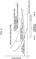
- the broken line plots a motor output driving force that is a value obtained by converting the motor output torque (the rated torque) in Fig. 3 into a driving force
- the dotted chain line plots an EV travel driving force obtained by subtracting the driving force of the engine start torque part in Fig. 3 from the motor output driving force (a value obtained by converting the EV travel torque part shown in Fig. 3 into a driving force)
- the solid line plots an EV travel request driving force (the sum of the running resistance and the predetermined acceleration margin part).
- the engine is started by using the first engine start system (the motor/generator 6), when the vehicle speed VSP during the EV travel becomes VSP_s in Fig. 4 or higher, the EV travel driving force (the dotted chain line) of the motor/generator 6 used for the EV travel becomes smaller than the EV travel request driving force (the solid line), and the EV travel only with the motor/generator 6 becomes unavailable because of insufficiency of the driving torque of the motor/generator 6.
- the mode has to be changed to the HEV travel mode with the cooperation of the engine 1 and the motor/generator 6. This may narrow the EV mode range that provides an improvement in specific fuel consumption. Hence, the fuel efficiency of the vehicle may be degraded.
- the predetermined vehicle speed VSP_s used in step S11 is determined as a vehicle speed value denoted by the same reference sign in Fig. 4 .
- step S11 if it is determined that the vehicle speed VSP during the EV travel is a vehicle speed lower than the predetermined vehicle speed VSP_s (see Fig. 4 ), the engine start control using the first engine start system is executed in step S12.
- the presence of an engine start request is checked by checking the presence of a mode change request from the EV mode to the HEV mode, and if the engine start request is generated, the engine is started by using the first engine start system (the motor/generator 6) such that the target engaging capacity tTc1 of the first clutch 7 in Fig. 1 is set to the predetermined capacity with which the first clutch 7 is engaged or larger and the target motor torque tTm is set to the motor torque value with which the engine 1 can be cranked or larger.
- the first engine start system the motor/generator 6
- steps S11 and S12 correspond to an engine start system selecting unit according to an aspect of the present invention.
- the vehicle speed VSP during the EV travel is a low vehicle speed of VSP ⁇ VSP_s
- the EV travel driving force (the dotted chain line in Fig. 4 ) of the motor/generator 6 used for the EV travel is equal to or larger than the EV travel request driving force (the solid line in Fig. 4 ).
- the EV travel only with the motor/generator 6 is available, and the above-mentioned problem relating to the degradation in fuel efficiency does not occur.
- the EV travel driving force (the dotted chain line in Fig. 4 ) of the motor/generator 6 used for the EV travel is smaller than the EV travel request driving force (the solid line in Fig. 4 ).
- the EV travel only with the motor/generator 6 is not available because of insufficiency of the driving force.
- the mode has to be changed to the HEV travel with the cooperation of the engine 1 and the motor/generator 6. This may narrow the EV mode range that provides an improvement in specific fuel consumption. Hence, the fuel efficiency of the vehicle may be degraded.
- step S11 if the vehicle speed VSP during the EV travel is in a vehicle speed range of VSP ⁇ VSP_s (step S11), the control goes to step S13, and the engine start control is executed as follows by effectively using the second engine start system (the starter motor 8) that is used when the engine is started at low temperatures but is rarely used in other situations.
- the second engine start system the starter motor 8
- the engine is started by using the second engine start system (the starter motor 8).
- steps S11 and S13 correspond to an engine start system selecting unit according to an aspect of the present invention.
- step S11 if the vehicle speed VSP during the EV travel is in the vehicle speed range of VSP ⁇ VSP_s (step S11), if the engine 1 is started by using the second engine start system (the starter motor 8) for starting the engine at low temperatures (S13), the restricted rated torque of the motor/generator 6 does not have to cover the engine start torque part.
- the motor output driving force of the motor/generator 6 indicated by the broken line in the same drawing can be entirely used as the EV travel driving force.
- the EV travel only with the motor/generator 6 is available until the vehicle speed VSP reaches a vehicle speed VSP_u at which the motor output driving force indicated by the broken line in Fig. 4 becomes' smaller than the EV travel request driving force indicated by the solid line.
- the timing at which the mode is changed to the HEV travel with the cooperation of the engine 1 and the motor/generator 6 can be delayed until the vehicle speed VSP reaches the vehicle speed VSP_u.
- the EV mode range that provides an improvement in specific fuel consumption can expand from VSP_s to VSP_u as indicated by an arrow in Fig. 4 .
- the fuel efficiency of the vehicle can be improved as shown in Fig. 5 by the amount corresponding to the expansion of the EV mode range.
- step S11 and S12 if the engine start request is generated in a vehicle speed range lower than the predetermined vehicle speed VSP_s in which the EV travel driving force of the motor/generator 6 indicated by the dotted chain line in Fig. 4 is larger than the EV travel request driving force indicated by the solid line in the same drawing (steps S11 and S12), the engine start control using the first engine start system (the motor/generator 6) is executed (step S12). If the vehicle speed VSP during the EV travel is the predetermined vehicle speed VSP_s or higher (steps S11 and S13), the engine start control using the second engine start system (the starter motor 8) is executed (step S13).
- the restricted rated torque of the motor/generator 6 does not have to cover the engine start torque part, and the motor output driving force of the motor/generator 6 indicated by the broken line in Fig. 4 can be entirely used as the EV travel driving force.
- the EV travel only with the motor/generator 6 is available until the vehicle speed VSP reaches the vehicle speed VSP_u at which the motor output driving force indicated by the broken line in Fig. 4 becomes smaller than the EV travel request driving force indicated by the solid line.
- the change of mode to the HEV travel with the cooperation of the engine 1 and the motor/generator 6 can extend to the vehicle speed VSP_u.
- the EV mode range can expand from VSP_s to VSP_u as indicated by the arrow in Fig. 4 .
- the fuel efficiency of the vehicle can be improved by the amount corresponding to the expansion of the EV mode range.
- the engine start control using the first engine start system (the motor/generator 6) is executed or the engine start control using the second engine start system (the starter motor 8) is executed, depending on whether or not the vehicle speed VSP during the EV travel is lower than the predetermined vehicle speed VSP_s.
- the motor/generator rotation speed Nm during the EV travel is used as rotation speed information during the EV travel instead of the vehicle speed VSP during the EV travel in order to crank the engine 1 with the motor rotation speed that can generate the rated torque of the motor/generator 6 if start-up of the engine employs the motor/generator 6 (the first engine start system).
- the rotation speed that can generate the rated torque is determined as a predetermined rotation speed. If the motor/generator rotation speed Nm during the EV travel is smaller than the predetermined rotation speed (the rotation speed that can generate the rated torque), the engine start control using the first engine start system (the motor/generator 6) is executed, and if the motor/generator rotation speed Nm during the EV travel is the predetermined rotation speed (the rotation speed that can generate the rated torque) or larger, the engine start control using the second engine start system (the starter motor 8) is executed.
- the fuel efficiency can be improved by the expansion of the EV mode range that provides an improvement in fuel efficiency.
- a first engine start system and a second engine start system are provided, the first engine start system is used if rotation speed information is lower than a predetermined speed, and the second engine start system is used if the rotation speed information is the predetermined speed or higher.
- the rotation speed information is a vehicle speed during electric travel.
- the predetermined vehicle speed is defined.
- the rotation speed information is a motor/generator rotation speed during the electric travel.
- the predetermined rotation speed is defined.
Landscapes
- Engineering & Computer Science (AREA)
- Transportation (AREA)
- Mechanical Engineering (AREA)
- Chemical & Material Sciences (AREA)
- Combustion & Propulsion (AREA)
- Automation & Control Theory (AREA)
- Electric Propulsion And Braking For Vehicles (AREA)
- Hybrid Electric Vehicles (AREA)
- Control Of Vehicle Engines Or Engines For Specific Uses (AREA)
Abstract
Description
- The present invention relates to an engine start control device for a hybrid vehicle that includes an engine, a first clutch, a motor/generator, a second clutch, and driving wheels arranged in order of a transmission path and can select electric travel only with the motor/generator or hybrid travel with the cooperation of the engine and the motor/generator, through engaging and disengaging control of the first and second clutches.
- There is known, as the above-described hybrid vehicle, a one-motor two-clutch parallel hybrid vehicle, for example, described in Japanese Unexamined Patent Application Publication No.
2010-179865 - This hybrid vehicle can select an EV mode for electric (EV) travel with the motor/generator if the first clutch is disengaged and the second clutch is engaged, and a HEV mode for hybrid (HEV) travel with the cooperation of the motor/generator and the engine if both the first and second clutches are engaged.
- In the one-motor two-clutch parallel hybrid vehicle, if a request driving force is increased, for example, because an accelerator pedal is depressed during travel in the EV mode that is selected in a small-load and low-rotation-speed situation and the request driving force is no longer provided only by the motor/generator, the mode is changed to the HEV travel (the HEV mode) with the cooperation of the motor/generator and the engine.
- To start the engine for changing the mode from the EV mode to the HEV mode, the first clutch, which is in the disengaged state in the EV mode, is engaged, and the engine is started by a motor torque from the motor/generator.
- However, to ensure start-up of the engine as described in Japanese Unexamined Patent Application Publication No.
2010-179865 - Meanwhile, the motor/generator is desired to have a rated torque as small as possible and is desired to be downsized in view of the cost and mounting space of the motor/generator. Thus, the amplitude of the rated torque is restricted.
- However, although the rated torque of the motor/generator is restricted, the required acceleration torque margin part and engine start torque part are almost determined, and these margin part and torque part cannot be decreased.
- Hence, the driving torque part obtained by subtracting the acceleration torque margin part and engine start torque part from the rated torque of the motor/generator becomes small.
- If the driving torque part becomes small, the travel in the EV mode only with the motor/generator becomes unavailable at an early timing (even at a low vehicle speed) because of insufficiency of the torque. Thus, the mode has to be changed to the HEV mode with the cooperation of the engine and the motor/generator at an early timing (even at a low vehicle speed).
- This may narrow an EV mode range that provides an improvement in specific fuel consumption. Hence, fuel efficiency of the vehicle may be degraded.
- In the case of the one-motor two-clutch parallel hybrid vehicle, in addition to a first engine start system that starts the engine with the motor/generator, a second engine start system that starts the engine with a dedicated starter motor is provided in view of engine startability at low temperatures. The second engine start system is advantageous for starting the engine at low temperatures; however, the starter motor is less frequently used in normal situations and is not effectively used. Hence, an object of the present invention is to provide an engine start control device for a hybrid vehicle that addresses the problem relating to the fuel efficiency (i.e., the problem in which the EV mode range is narrowed) by effectively using the second engine start system.
- The solution of the object is achieved by the features of claim 1. The dependent claims contain advantageous embodiments of the invention.
- To attain the object, an engine start control device for a hybrid vehicle according to an aspect of the present invention has the following configuration.
- First, describing the hybrid vehicle serving as a precondition, the hybrid vehicle includes an engine, a first clutch, a motor/generator, a second clutch, and driving wheels arranged in order of a transmission path and can select electric travel only with the motor/generator from among the engine and the motor/generator or hybrid travel with the cooperation of the engine and the motor/generator, through engaging and disengaging control of the first and second clutches. The engine start control device used for the hybrid vehicle and serving as a precondition includes a first engine start system that engages the first clutch and starts the engine with the motor/generator; and a second engine start system that starts the engine with a starter motor for starting the engine.
- Then, the aspect of the present invention has a feature that the engine start control device includes an engine start system selecting unit.
- The engine start system selecting unit selects the first engine start system or the second engine start system so that, based on rotation speed information relating to the electric travel, engine start control using the first engine start system is executed if the rotation speed information is lower than a predetermined speed and engine start control using the second engine start system is executed if the rotation speed information is the predetermined speed or higher.
- With the engine start control device for the hybrid vehicle according to the aspect of the present invention, the engine start control using the first engine start system is executed if the rotation speed information relating to the electric travel is lower than the predetermined speed, and the engine start control using the second engine start system is executed if the rotation speed information relating to the electric travel is the predetermined speed or higher. Accordingly, the following advantage can be attained.
- If only the engine start control using the first engine start system is executed, since the rated torque of the motor/generator is restricted, the electric travel only with the motor/generator becomes unavailable at an early timing (even at a low rotation speed) because of insufficiency of the driving torque of the motor/generator as described above, and the mode has to be changed to the hybrid travel with the cooperation of the engine and the motor/generator at an early timing (even at a low rotation speed). The electric travel range is narrowed and the fuel efficiency is degraded.
- However, with the aspect of the present invention, the engine start control using the second engine start system is executed if the rotation speed information relating to the electric travel is the predetermined speed or higher. The restricted rated torque of the motor/generator does not have to cover the engine start toque part during the engine start control using the second engine start system. Occurrence of insufficiency of the driving torque of the motor/generator can be delayed by the amount corresponding to the engine start torque part. The electric travel only with the motor/generator can be continued until its rotation speed reaches a higher rotation speed. Accordingly, the electric travel range can expand, and the fuel efficiency can be improved.
-
-
Fig. 1 is a schematic system diagram showing a power train and a control system of a hybrid vehicle including an engine start control device according to an embodiment of the present invention; -
Fig. 2 is a flowchart showing an engine start control program executed by a hybrid controller of the power train control system shown inFig. 1 ; -
Fig. 3 is a graph used for explaining a procedure when a motor output torque (a rated torque) of a motor/generator shown inFig. 1 is determined; -
Fig. 4 is a graph showing a motor output driving force by the motor output torque (the rated torque) shown inFig. 3 together with an EV travel driving force provided by the motor/generator for EV travel and an EV travel request driving force; and -
Fig. 5 is a graph showing a change characteristic of the improvement rate of fuel efficiency attained by engine start control shown inFig. 2 . - An aspect of the present invention is described in detail based on embodiments shown in the drawings. Power Train of Hybrid Vehicle
-
Fig. 1 illustrates a power train and a control system of a hybrid vehicle including an engine start control device according to an embodiment of the present invention. - This hybrid vehicle is formed by using a front-engine front-wheel drive car (a front-wheel drive car) as a base vehicle and configuring the vehicle as a hybrid vehicle. Referring to
Fig. 1 , reference sign 1 denotes an engine serving as a power source, 2FL and 2FR respectively denote left and right front wheels (left and right driving wheels), and 3RL and 3RR respectively denote left and right rear wheels (left and right driven wheels). - In the power train of the hybrid vehicle shown in
Fig. 1 , a V-belt continuouslyvariable transmission 4 is arranged at one side in a vehicle width direction of the engine 1 that is transversely mounted like a typical front-wheel drive car. A motor/generator 6 (MG, a power source) is coupled with ashaft 5 that transmits rotation from the engine 1 (more particularly, acrank shaft 1a) to aninput shaft 4a of the V-belt continuouslyvariable transmission 4. - The motor/generator 6 includes a ring-like stator fixed in a housing and a rotor arranged in the stator coaxially with the stator with a predetermined air gap interposed therebetween. The motor/generator 6 acts as an electric motor (a motor) or a generator (a power generator) in accordance with a request of a driving state, and is arranged between the engine 1 and the V-belt continuously
variable transmission 4. - The motor/generator 6 penetrates through the
shaft 5 and is coupled with the center of the rotor. The motor/generator 6 uses theshaft 5 as a motor/generator shaft. - A
first clutch 7 is arranged between the motor/generator 6 and the engine 1, and more particularly between the motor/generator shaft 5 and anengine crank shaft 1a. Thefirst clutch 7 can connect and disconnect the engine 1 with and from the motor/generator 6. - The
first clutch 7 can continuously change a transmission torque (clutch engaging) capacity. For example, thefirst clutch 7 is a wet multi-disk clutch that can change the transmission torque (clutch engaging) capacity by continuously controlling a clutch hydraulic fluid amount and a clutch hydraulic fluid pressure by a proportional solenoid. - The motor/generator 6 and the V-belt continuously
variable transmission 4 are directly coupled with each other through direct coupling between the motor/generator shaft 5 and thetransmission input shaft 4a. Asecond clutch 9 is arranged in the middle of thetransmission input shaft 4a. - While the V-belt continuously
variable transmission 4 may be a typical continuously variable transmission, a torque converter is removed from the continuously variable transmission and the motor/generator 6 is directly coupled with thetransmission input shaft 4a. If thetransmission input shaft 4a is in an engaged state, the speed of rotation from theinput shaft 4a is changed with a speed reduction ratio corresponding to a pulley ratio of the V-belt continuously variable transmission mechanism, and the result rotation is output to anoutput shaft 4b. - The rotation output from the
output shaft 4b of the V-belt continuouslyvariable transmission 4 is transmitted to the left and right front wheels 2FL and 2FR through a differential gear device (not shown), and is used for travel of the vehicle. - It is to be noted that the V-belt continuously
variable transmission 4 may be alternatively a stepped automatic transmission. - Also, the
second clutch 9 that connects and disconnects the motor/generator 6 with and from the driving wheels 2FL and 2FR and that is necessary for the hybrid vehicle may be arranged downstream of the V-belt continuouslyvariable transmission 4 instead of being arranged in the middle of thetransmission input shaft 4a as shown inFig. 1 . - It is to be noted that the
second clutch 9 may continuously change a transmission torque capacity (a clutch engaging capacity) like thefirst clutch 7. - Travel modes of the power train described above with reference to
Fig. 1 are described below. - In the power train shown in
Fig. 1 , if electric travel (EV mode) used in a small-load and low-vehicle-speed situation such as start-up from a stopped state is requested, thefirst clutch 7 is disengaged and thesecond clutch 9 is engaged. - If the motor/generator 6 is driven in this state, only output rotation from the motor/generator 6 reaches the
transmission input shaft 4a. Then, the V-belt continuouslyvariable transmission 4 changes the speed of rotation to theinput shaft 4a in accordance with a selected pulley ratio and outputs the result rotation from thetransmission output shaft 4b. - The rotation from the
transmission output shaft 4b reaches the front wheels 2FL and 2FR through the differential gear device (not shown), so that the vehicle travels by electric travel (EV travel) only with the motor/generator 6. - If hybrid travel (HEV mode) used during, for example, high-speed travel or large-load travel is requested, the
first clutch 7 is engaged and thesecond clutch 9 is engaged. - In this state, both the output rotation from the engine 1 and the output rotation from the motor/generator 6 reach the
transmission input shaft 4a by the cooperation of the engine 1 and the motor/generator 6. The V-belt continuouslyvariable transmission 4 changes the speed of rotation to theinput shaft 4a in accordance with a selected pulley ratio, and outputs the result rotation from thetransmission output shaft 4b. - The rotation from the
transmission output shaft 4b reaches the front wheels 2FL and 2FR through the differential gear device (not shown), so that the vehicle travels by hybrid travel (HEV travel) with the cooperation of the engine 1 and the motor/generator 6. - During the HEV travel, if the amount of energy is excessive when the engine 1 is operated with an optimal fuel efficiency, the excessive energy is converted into electric power such that the motor/generator 6 acts as a generator by using the excessive energy. The generated electric power is charged to be used for motor driving of the motor/generator 6. Accordingly, the fuel efficiency of the engine 1 can be improved.
- The EV mode or the HEV mode is generally selected as follows.
- Selection of the EV mode in which the electric (EV) travel is provided only by the motor/generator 6 is commanded if the vehicle speed is a predetermined vehicle speed (for example, 30 km/h) or lower, the accelerator pedal opening is a predetermined opening (for example, 1/8) or smaller or the rate of change in accelerator pedal opening is a predetermined acceleration request (for example, 0.05 G) or smaller, the motor/generator rotation speed is a predetermined motor rotation speed (for example, 1000 rpm) or smaller, the engine cooling water temperature is a predetermined water temperature (for example, 40°C) or higher, and the battery state of charge (SOC) is a predetermined state of charge (for example, 60%) or more.
- If even one of the EV-mode selection conditions is not satisfied, i.e., for example, if the accelerator pedal opening exceeds the predetermined opening (1/8) or the rate of change in accelerator pedal opening exceeds the predetermined acceleration request (0.05 G) because of depression of the accelerator pedal during the EV travel, or if the battery state of charge SOC is less than the predetermined state of charge (60%), selection of the HEV mode in which the hybrid (HEV) travel is provided by the cooperation of the engine 1 and the motor/generator 6 is commanded.
- Next, the control system for the engine 1, the motor/generator 6, the
first clutch 7, and thesecond clutch 9 that form the power train of the hybrid vehicle is briefly described with reference toFig. 1 . - This control system includes a
hybrid controller 11 that provides integrated control for operating points of the power train. The operating points of the power train are defined by a target engine torque tTe, a target motor/generator torque tTm, a target engaging capacity tTc1 of the first clutch 7 (a first clutch engaging pressure command value tPc1), and a target engaging capacity tTc2 of the second clutch 9 (a second clutch engaging pressure command value tPc2). - The
hybrid controller 11 also generates a starter motor control signal Ssm that provides ON/OFF control for astarter motor 8 for starting the engine at low temperatures. The starter motor control signal Ssm is used for engine start control (described later) that is the aim of the present invention. - In order to determine the operating points of the power train and to generate an engine stop control signal, the
hybrid controller 11 receives a signal from anengine rotation sensor 12 that detects an engine rotation speed Ne, a signal from a motor/generator rotation sensor 13 that detects a motor/generator rotation speed Nm, a signal from aninput rotation sensor 14 that detects a transmission input rotation speed Ni, a signal from anoutput rotation sensor 15 that detects a transmission output rotation speed No (a vehicle speed VSP), a signal from an acceleratorpedal opening sensor 16 that detects a depressed amount of the accelerator pedal (an accelerator pedal opening APO), a signal from acharge state sensor 17 that detects a battery state of charge SOC of a high-voltage battery 31 that charges electric power for the motor/generator 6, and a signal from an engine coolingwater temperature sensor 18 that detects an engine cooling water temperature Temp. - The
hybrid controller 11 selects a drive mode (the EV mode, the HEV mode) that can provide a driving force of the vehicle desired by a driver, and calculates the target engine torque tTe, the target motor/generator torque tTm, the first clutch target engaging capacity tTc1, and the second clutch target engaging capacity tTc2, by using the accelerator pedal opening APO, the battery state of charge SOC, and the transmission output rotation speed No (the vehicle speed VSP) from among the aforementioned input information. - The target engine torque tTe is fed to an
engine controller 32. Theengine controller 32 controls the engine 1 such that the engine torque becomes the target engine torque tTe by using the engine rotation speed Ne detected by thesensor 12 and the target engine torque tTe, through throttle opening control or fuel-injection amount control for achieving the target engine torque tTe based on the engine rotation speed Ne. - The target motor/generator torque tTm is fed to a
motor controller 33. Themotor controller 33 converts electric power of the high-voltage battery 31 through DC/AC conversion by aninverter 34, feeds the electric power to the stator of the motor/generator 6 under the control of theinverter 34, and controls the motor/generator 6 such that the motor/generator torque meets the target motor/generator torque tTm. - If the target motor/generator torque tTm is a value that requests the motor/generator 6 to execute regenerative braking, the
motor controller 33 gives a power generation load, which prevents the high-voltage battery 31 from being overcharged, to the motor/generator 6 in accordance with the battery state of charge SOC detected by thesensor 17, through theinverter 34. Themotor controller 33 converts the electric power generated by the motor/generator 6 through the regenerative braking, through AC/DC conversion by theinverter 34, and the electric power is charged in the high-voltage battery 31. - The first clutch target engaging capacity tTc1 is fed to a first
clutch controller 36. The firstclutch controller 36 executes engaging capacity control for thefirst clutch 7 by controlling the engaging pressure of thefirst clutch 7 through a first clutch engagingpressure control unit 37 so that an engaging pressure Pc1 of thefirst clutch 7 detected by a sensor 19 becomes the first clutch engaging pressure command value tPc1 through comparison between the first clutch engaging pressure command value tPc1 corresponding to the first clutch target engaging capacity tTc1 and the engaging pressure Pc1 of thefirst clutch 7. - The second clutch target engaging capacity tTc2 is fed to a
transmission controller 38. Thetransmission controller 38 executes engaging capacity control for thesecond clutch 9 by controlling the engaging pressure of thesecond clutch 9 through a second clutch engagingpressure control unit 39 so that an engaging pressure Pc2 of thesecond clutch 9 detected by asensor 20 becomes the second clutch engaging pressure command value tPc2 through comparison between the second clutch engaging pressure command value tPc2 corresponding to the second clutch target engaging capacity tTc2 and the engaging pressure Pc2 of thesecond clutch 9. - The
transmission controller 38 obtains a pulley ratio optimal to the current driving state based on the transmission output rotation speed No (the vehicle speed VSP) detected by thesensor 15 and the accelerator pedal opening APO detected by thesensor 16 with reference to a predetermined speed change map, and thetransmission controller 38 continuously changes the speed from the current pulley ratio to the optimal pulley ratio. - The brief explanation for the normal control executed by the control system in
Fig. 1 is provided above. - In this embodiment, the engine start control that is the aim of the present invention is executed as described below such that the
hybrid controller 11 inFig. 1 executes an engine start control program shown inFig. 2 . - Start-up of the engine includes a method using a first engine start system that starts the engine by engaging the
first clutch 7 and cranking the engine 1 by the motor/generator 6, and a method using a second engine start system that starts the engine such that thestarter motor 8 cranks the engine 1 with electric power from a low-voltage battery. The second engine start system using thestarter motor 8 is installed for independently starting combustion of the engine 1 in order to ensure engine startability at low temperatures. - The engine start control program in
Fig. 2 is executed in a situation other than the situation at low temperatures that needs to ensure the engine startability. In step S11, it is checked whether or not the vehicle speed VSP during the EV travel while the engine 1 is stopped is a vehicle speed lower than a predetermined vehicle speed VSP_s. - Now, the predetermined vehicle speed VSP_s is described.
- To allow the motor/generator 6 serving as the first engine start system to start the engine 1 as described above, the motor output torque (the rated torque) of the motor/generator 6 that varies as exemplarily shown in
Fig. 3 with respect to the vehicle speed VSP (the motor/generator rotation speed Nm) has to have the amplitude that covers an electric (EV) travel torque part that is the sum of a driving torque part corresponding to a running resistance (air resistance, rolling resistance, etc.) of the vehicle and an acceleration torque margin part corresponding to a predetermined acceleration margin part of the vehicle, and the engine start torque (cranking torque) part. - Meanwhile, the motor/generator 6 is desired to have the motor output torque (the rated torque) as small as possible and is desired to be downsized in view of the cost and mounting space of the motor/generator 6. The amplitude of the motor output torque (the rated torque) is restricted.
- However, although the motor output torque (the rated torque) of the motor/generator 6 is restricted, the required acceleration torque margin part and the engine start torque part are almost determined, and these margin part and torque part cannot be decreased.
- Hence, the driving torque part obtained by subtracting the acceleration torque margin part and engine start torque part from the rated torque of the motor/generator becomes small.
- If the driving torque part becomes small, the travel in the EV mode only with the motor/generator 6 becomes unavailable at an early timing (even at a low vehicle speed) because of insufficiency of the torque. Thus, the mode has to be changed to the HEV mode with the cooperation of the engine 1 and the motor/generator 6 at an early timing (even at a low vehicle speed).
- This may narrow an EV mode range that provides an improvement in specific fuel consumption. Hence, the fuel efficiency of the vehicle may be degraded.
- Referring to
Fig. 4 , the broken line plots a motor output driving force that is a value obtained by converting the motor output torque (the rated torque) inFig. 3 into a driving force, the dotted chain line plots an EV travel driving force obtained by subtracting the driving force of the engine start torque part inFig. 3 from the motor output driving force (a value obtained by converting the EV travel torque part shown inFig. 3 into a driving force), and the solid line plots an EV travel request driving force (the sum of the running resistance and the predetermined acceleration margin part). - If the engine is started by using the first engine start system (the motor/generator 6), when the vehicle speed VSP during the EV travel becomes VSP_s in
Fig. 4 or higher, the EV travel driving force (the dotted chain line) of the motor/generator 6 used for the EV travel becomes smaller than the EV travel request driving force (the solid line), and the EV travel only with the motor/generator 6 becomes unavailable because of insufficiency of the driving torque of the motor/generator 6. - Hence, if the vehicle speed VSP during the EV travel becomes VSP ≥ VSP_s, the mode has to be changed to the HEV travel mode with the cooperation of the engine 1 and the motor/generator 6. This may narrow the EV mode range that provides an improvement in specific fuel consumption. Hence, the fuel efficiency of the vehicle may be degraded.
- Owing to this, in this embodiment, the predetermined vehicle speed VSP_s used in step S11 is determined as a vehicle speed value denoted by the same reference sign in
Fig. 4 . - In step S11, if it is determined that the vehicle speed VSP during the EV travel is a vehicle speed lower than the predetermined vehicle speed VSP_s (see
Fig. 4 ), the engine start control using the first engine start system is executed in step S12. - When the engine start control using the first engine start system is executed, the presence of an engine start request is checked by checking the presence of a mode change request from the EV mode to the HEV mode, and if the engine start request is generated, the engine is started by using the first engine start system (the motor/generator 6) such that the target engaging capacity tTc1 of the
first clutch 7 inFig. 1 is set to the predetermined capacity with which thefirst clutch 7 is engaged or larger and the target motor torque tTm is set to the motor torque value with which the engine 1 can be cranked or larger. - Hence, steps S11 and S12 correspond to an engine start system selecting unit according to an aspect of the present invention.
- Meanwhile, if the vehicle speed VSP during the EV travel is a low vehicle speed of VSP < VSP_s, even if the motor/generator 6 is used for starting the engine, the EV travel driving force (the dotted chain line in
Fig. 4 ) of the motor/generator 6 used for the EV travel is equal to or larger than the EV travel request driving force (the solid line inFig. 4 ). The EV travel only with the motor/generator 6 is available, and the above-mentioned problem relating to the degradation in fuel efficiency does not occur. - Therefore, if the vehicle speed VSP during the EV travel is in the vehicle speed range of VSP ≥ VSP_s, when the motor/generator 6 is used for starting the engine, the EV travel driving force (the dotted chain line in
Fig. 4 ) of the motor/generator 6 used for the EV travel is smaller than the EV travel request driving force (the solid line inFig. 4 ). The EV travel only with the motor/generator 6 is not available because of insufficiency of the driving force. The mode has to be changed to the HEV travel with the cooperation of the engine 1 and the motor/generator 6. This may narrow the EV mode range that provides an improvement in specific fuel consumption. Hence, the fuel efficiency of the vehicle may be degraded. - Owing to this, according to this embodiment, if the vehicle speed VSP during the EV travel is in a vehicle speed range of VSP ≥ VSP_s (step S11), the control goes to step S13, and the engine start control is executed as follows by effectively using the second engine start system (the starter motor 8) that is used when the engine is started at low temperatures but is rarely used in other situations.
- In step S13, the presence of the engine start request is checked by checking the presence of the mode change request from the EV mode to the HEV mode, and if the engine start request is generated, the starter motor control signal Ssm in
Fig. 1 is set to Ssm = ON, to drive thestarter motor 8. Thus, the engine is started by using the second engine start system (the starter motor 8). - Hence, steps S11 and S13 correspond to an engine start system selecting unit according to an aspect of the present invention.
- As described above, if the vehicle speed VSP during the EV travel is in the vehicle speed range of VSP ≥ VSP_s (step S11), if the engine 1 is started by using the second engine start system (the starter motor 8) for starting the engine at low temperatures (S13), the restricted rated torque of the motor/generator 6 does not have to cover the engine start torque part. In the vehicle speed range of VSP ≥ VSP_s in
Fig. 4 , the motor output driving force of the motor/generator 6 indicated by the broken line in the same drawing can be entirely used as the EV travel driving force. - Accordingly, the EV travel only with the motor/generator 6 is available until the vehicle speed VSP reaches a vehicle speed VSP_u at which the motor output driving force indicated by the broken line in
Fig. 4 becomes' smaller than the EV travel request driving force indicated by the solid line. The timing at which the mode is changed to the HEV travel with the cooperation of the engine 1 and the motor/generator 6 can be delayed until the vehicle speed VSP reaches the vehicle speed VSP_u. - Accordingly, the EV mode range that provides an improvement in specific fuel consumption can expand from VSP_s to VSP_u as indicated by an arrow in
Fig. 4 . The fuel efficiency of the vehicle can be improved as shown inFig. 5 by the amount corresponding to the expansion of the EV mode range. - With the engine start control of this embodiment with reference to
Fig. 2 , if the engine start request is generated in a vehicle speed range lower than the predetermined vehicle speed VSP_s in which the EV travel driving force of the motor/generator 6 indicated by the dotted chain line inFig. 4 is larger than the EV travel request driving force indicated by the solid line in the same drawing (steps S11 and S12), the engine start control using the first engine start system (the motor/generator 6) is executed (step S12). If the vehicle speed VSP during the EV travel is the predetermined vehicle speed VSP_s or higher (steps S11 and S13), the engine start control using the second engine start system (the starter motor 8) is executed (step S13). Accordingly, if the vehicle speed VSP during the EV travel is in the vehicle speed range of VSP ≥ VSP_s, the restricted rated torque of the motor/generator 6 does not have to cover the engine start torque part, and the motor output driving force of the motor/generator 6 indicated by the broken line inFig. 4 can be entirely used as the EV travel driving force. - Accordingly, the EV travel only with the motor/generator 6 is available until the vehicle speed VSP reaches the vehicle speed VSP_u at which the motor output driving force indicated by the broken line in
Fig. 4 becomes smaller than the EV travel request driving force indicated by the solid line. The change of mode to the HEV travel with the cooperation of the engine 1 and the motor/generator 6 can extend to the vehicle speed VSP_u. - Hence, the EV mode range can expand from VSP_s to VSP_u as indicated by the arrow in
Fig. 4 . The fuel efficiency of the vehicle can be improved by the amount corresponding to the expansion of the EV mode range. - In the above-described embodiment, it is determined whether the engine start control using the first engine start system (the motor/generator 6) is executed or the engine start control using the second engine start system (the starter motor 8) is executed, depending on whether or not the vehicle speed VSP during the EV travel is lower than the predetermined vehicle speed VSP_s. Alternatively, it may be determined whether the engine start control using the first engine start system (the motor/generator 6) is executed or the engine start control using the second engine start system (the starter motor 8) is executed, depending on the motor/generator rotation speed Nm during the EV travel.
- The motor/generator rotation speed Nm during the EV travel is used as rotation speed information during the EV travel instead of the vehicle speed VSP during the EV travel in order to crank the engine 1 with the motor rotation speed that can generate the rated torque of the motor/generator 6 if start-up of the engine employs the motor/generator 6 (the first engine start system).
- In this case, the rotation speed that can generate the rated torque is determined as a predetermined rotation speed. If the motor/generator rotation speed Nm during the EV travel is smaller than the predetermined rotation speed (the rotation speed that can generate the rated torque), the engine start control using the first engine start system (the motor/generator 6) is executed, and if the motor/generator rotation speed Nm during the EV travel is the predetermined rotation speed (the rotation speed that can generate the rated torque) or larger, the engine start control using the second engine start system (the starter motor 8) is executed.
- With this configuration, an advantage similar to that of the illustrated embodiment can be attained. The fuel efficiency can be improved by the expansion of the EV mode range that provides an improvement in fuel efficiency.
- Main aspects of the invention: A first engine start system and a second engine start system are provided, the first engine start system is used if rotation speed information is lower than a predetermined speed, and the second engine start system is used if the rotation speed information is the predetermined speed or higher. Further, the rotation speed information is a vehicle speed during electric travel. Moreover, the predetermined vehicle speed is defined. Additionally, the rotation speed information is a motor/generator rotation speed during the electric travel. Finally, the predetermined rotation speed is defined.
Claims (5)
- An engine start control device for a hybrid vehicle that includes an engine, a first clutch, a motor/generator, a second clutch, and driving wheels arranged in order of a transmission path and can select electric travel only with the motor/generator from among the engine and the motor/generator or hybrid travel with cooperation of the engine and the motor/generator, through engaging and disengaging control of the first and second clutches, the engine start control device comprising:a first engine start system that engages the first clutch and starts the engine with the motor/generator;a second engine start system that starts the engine with a starter motor for starting the engine; andan engine start system selecting unit that selects the first engine start system or the second engine start system so that, based on rotation speed information relating to the electric travel, engine start control using the first engine start system is executed if the rotation speed information is lower than a predetermined speed and engine start control using the second engine start system is executed if the rotation speed information is the predetermined speed or higher.
- The engine start control device for the hybrid vehicle according to claim 1, wherein the engine start system selecting unit selects the first engine start system or the second engine start system by using a vehicle speed during the electric travel as the rotation speed information so that the engine start control using the first engine start system is executed if the vehicle speed is lower than a predetermined vehicle speed and the engine start control using the second engine start system is executed if the vehicle speed is the predetermined vehicle speed or higher.
- The engine start control device for the hybrid vehicle according to claim 2, wherein the predetermined vehicle speed is a vehicle speed when an electric travel driving force that can be generated by an electric travel torque part obtained by subtracting an engine start torque part required for starting the engine from a rated torque of the motor/generator is smaller than the sum of a running resistance and a predetermined acceleration margin part of the vehicle.
- The engine start control device for the hybrid vehicle according to claim 1, wherein the engine start system selecting unit selects the first engine start system or the second engine start system by using a motor/generator rotation speed during the electric travel as the rotation speed information so that the engine start control using the first engine start system is executed if the motor/generator rotation speed is smaller than a predetermined rotation speed and the engine start control using the second engine start system is executed if the motor/generator rotation speed is the predetermined rotation speed or larger.
- The engine start control device for the hybrid vehicle according to claim 4,
wherein a rated torque of the motor/generator is determined to correspond to the sum of an engine start torque part required for starting the engine and an electric travel torque part, and
wherein the predetermined rotation speed is a motor/generator rotation speed that can generate the rated torque of the motor/generator.
Applications Claiming Priority (1)
| Application Number | Priority Date | Filing Date | Title |
|---|---|---|---|
| JP2011126881A JP5899666B2 (en) | 2011-06-07 | 2011-06-07 | Engine start control device for hybrid vehicle |
Publications (3)
| Publication Number | Publication Date |
|---|---|
| EP2532549A2 true EP2532549A2 (en) | 2012-12-12 |
| EP2532549A3 EP2532549A3 (en) | 2018-04-18 |
| EP2532549B1 EP2532549B1 (en) | 2020-02-19 |
Family
ID=45893998
Family Applications (1)
| Application Number | Title | Priority Date | Filing Date |
|---|---|---|---|
| EP12001768.6A Active EP2532549B1 (en) | 2011-06-07 | 2012-03-15 | Engine start control device for hybrid vehicle |
Country Status (4)
| Country | Link |
|---|---|
| US (1) | US8755962B2 (en) |
| EP (1) | EP2532549B1 (en) |
| JP (1) | JP5899666B2 (en) |
| CN (1) | CN102815294B (en) |
Cited By (5)
| Publication number | Priority date | Publication date | Assignee | Title |
|---|---|---|---|---|
| EP3006293A4 (en) * | 2013-06-03 | 2016-06-15 | Nissan Motor | Hybrid vehicle control device |
| EP3050766A1 (en) * | 2013-09-26 | 2016-08-03 | Nissan Motor Co., Ltd. | Startup control device and startup control method for hybrid vehicle |
| CN108661838A (en) * | 2018-04-25 | 2018-10-16 | 北京长安汽车工程技术研究有限责任公司 | The starting method of hybrid vehicle and its engine, device, equipment |
| WO2021084172A1 (en) * | 2019-10-31 | 2021-05-06 | Psa Automobiles Sa | Method for starting an internal combustion engine in a hybrid traction architecture |
| EP3974637A3 (en) * | 2013-05-30 | 2022-04-20 | NISSAN MOTOR Co., Ltd. | Starting control device for internal combustion engines and starting control method |
Families Citing this family (28)
| Publication number | Priority date | Publication date | Assignee | Title |
|---|---|---|---|---|
| KR101294054B1 (en) * | 2011-06-01 | 2013-08-07 | 현대자동차주식회사 | Fuel cut mehod of hybrid vehicle |
| JP5899666B2 (en) * | 2011-06-07 | 2016-04-06 | 日産自動車株式会社 | Engine start control device for hybrid vehicle |
| WO2013077161A1 (en) * | 2011-11-25 | 2013-05-30 | 日産自動車株式会社 | Hybrid vehicle control device |
| US8892289B2 (en) | 2012-05-04 | 2014-11-18 | Ford Global Technologies, Llc | Methods and systems for operating a vehicle driveline |
| KR101371748B1 (en) * | 2012-10-29 | 2014-03-07 | 기아자동차(주) | Control method for hybrid vehicle |
| JP2014189032A (en) * | 2013-03-26 | 2014-10-06 | Toyota Motor Corp | Control system of vehicle |
| CN105102286B (en) * | 2013-04-01 | 2017-09-26 | 丰田自动车株式会社 | The stop control of internal combustion engine |
| JP6070855B2 (en) | 2013-10-10 | 2017-02-08 | 日産自動車株式会社 | Control device for hybrid vehicle |
| JP6183169B2 (en) * | 2013-11-14 | 2017-08-23 | 日産自動車株式会社 | Control device for hybrid vehicle |
| JP6303422B2 (en) * | 2013-11-14 | 2018-04-04 | 日産自動車株式会社 | Control device for hybrid vehicle |
| GB2523080A (en) * | 2014-02-12 | 2015-08-19 | Ford Global Tech Llc | An apparatus and method for starting an engine |
| JP6318909B2 (en) * | 2014-06-25 | 2018-05-09 | 三菱自動車工業株式会社 | Control device for hybrid vehicle |
| DE102014219221B4 (en) * | 2014-09-24 | 2022-12-01 | Robert Bosch Gmbh | Method for starting an internal combustion engine of a motor vehicle |
| JP5963904B1 (en) * | 2015-04-14 | 2016-08-03 | 三菱電機株式会社 | Control device and control method for hybrid vehicle |
| US9932914B2 (en) * | 2015-04-14 | 2018-04-03 | Ford Global Technologies, Llc | Method for increasing electric operation in hybrid electric vehicles |
| CN107107906B (en) * | 2015-04-30 | 2020-11-03 | 庞巴迪动力产品公司 | Method for engine braking of a vehicle with a continuously variable transmission |
| BR112017026235B1 (en) | 2015-06-08 | 2022-10-04 | Nissan Motor Co., Ltd | POWER GENERATION CONTROL DEVICE FOR A HYBRID VEHICLE |
| US10166855B2 (en) * | 2015-09-12 | 2019-01-01 | GM Global Technology Operations LLC | Vehicle, system, and method of calculating an engine torque request value |
| CN105128848B (en) * | 2015-09-15 | 2017-07-25 | 重庆长安汽车股份有限公司 | The control method of engine is started between a kind of traveling |
| JP6520661B2 (en) * | 2015-11-20 | 2019-05-29 | スズキ株式会社 | Control device for hybrid vehicle |
| US20170203666A1 (en) * | 2016-01-19 | 2017-07-20 | Ford Global Technologies, Llc | Battery charging system and servicing method |
| US9937919B2 (en) * | 2016-03-10 | 2018-04-10 | Ford Global Technologies, Llc | System and method for coupled and decoupled engine starting in a hybrid vehicle |
| JP6520908B2 (en) * | 2016-12-22 | 2019-05-29 | トヨタ自動車株式会社 | Hybrid vehicle |
| JP6978219B2 (en) * | 2017-04-18 | 2021-12-08 | トヨタ自動車株式会社 | Vehicle control device |
| US10112598B1 (en) | 2017-09-21 | 2018-10-30 | Ford Global Technologies, Llc | System and method of controlling engine torque of hybrid vehicle |
| JP6888528B2 (en) * | 2017-11-20 | 2021-06-16 | トヨタ自動車株式会社 | Hybrid vehicle control device |
| CN108327701B (en) * | 2018-02-22 | 2019-11-15 | 安徽江淮汽车集团股份有限公司 | A kind of starting control method and system |
| JP6975277B2 (en) * | 2020-02-28 | 2021-12-01 | 本田技研工業株式会社 | Vehicle control device |
Citations (1)
| Publication number | Priority date | Publication date | Assignee | Title |
|---|---|---|---|---|
| JP2010179865A (en) | 2009-02-09 | 2010-08-19 | Nissan Motor Co Ltd | Controller for hybrid vehicle |
Family Cites Families (9)
| Publication number | Priority date | Publication date | Assignee | Title |
|---|---|---|---|---|
| JP3775012B2 (en) * | 1997-08-29 | 2006-05-17 | アイシン・エィ・ダブリュ株式会社 | Hybrid drive device for vehicle |
| US6554088B2 (en) * | 1998-09-14 | 2003-04-29 | Paice Corporation | Hybrid vehicles |
| JP2001065437A (en) * | 1999-08-25 | 2001-03-16 | Honda Motor Co Ltd | Control device for hybrid vehicle |
| JP3649058B2 (en) * | 1999-10-08 | 2005-05-18 | トヨタ自動車株式会社 | Vehicle control apparatus having a plurality of prime movers |
| JP3852604B2 (en) * | 2003-05-13 | 2006-12-06 | トヨタ自動車株式会社 | HYBRID VEHICLE AND ENGINE START CONTROL METHOD |
| JP2006183547A (en) * | 2004-12-27 | 2006-07-13 | Nissan Motor Co Ltd | Engine start device for hybrid vehicle |
| JP4265572B2 (en) * | 2005-06-01 | 2009-05-20 | トヨタ自動車株式会社 | POWER OUTPUT DEVICE, VEHICLE MOUNTING THE SAME, AND METHOD FOR CONTROLLING POWER OUTPUT DEVICE |
| US8010247B2 (en) * | 2007-11-03 | 2011-08-30 | GM Global Technology Operations LLC | Method for operating an engine in a hybrid powertrain system |
| JP5899666B2 (en) * | 2011-06-07 | 2016-04-06 | 日産自動車株式会社 | Engine start control device for hybrid vehicle |
-
2011
- 2011-06-07 JP JP2011126881A patent/JP5899666B2/en active Active
-
2012
- 2012-03-05 US US13/411,923 patent/US8755962B2/en active Active
- 2012-03-06 CN CN201210056649.6A patent/CN102815294B/en active Active
- 2012-03-15 EP EP12001768.6A patent/EP2532549B1/en active Active
Patent Citations (1)
| Publication number | Priority date | Publication date | Assignee | Title |
|---|---|---|---|---|
| JP2010179865A (en) | 2009-02-09 | 2010-08-19 | Nissan Motor Co Ltd | Controller for hybrid vehicle |
Cited By (10)
| Publication number | Priority date | Publication date | Assignee | Title |
|---|---|---|---|---|
| EP3974637A3 (en) * | 2013-05-30 | 2022-04-20 | NISSAN MOTOR Co., Ltd. | Starting control device for internal combustion engines and starting control method |
| EP3006293A4 (en) * | 2013-06-03 | 2016-06-15 | Nissan Motor | Hybrid vehicle control device |
| US9452753B2 (en) | 2013-06-03 | 2016-09-27 | Nissan Motor Co., Ltd. | Control system for a plug-in hybrid vehicle |
| EP3050766A1 (en) * | 2013-09-26 | 2016-08-03 | Nissan Motor Co., Ltd. | Startup control device and startup control method for hybrid vehicle |
| EP3050766A4 (en) * | 2013-09-26 | 2017-05-03 | Nissan Motor Co., Ltd | Startup control device and startup control method for hybrid vehicle |
| US9744966B2 (en) | 2013-09-26 | 2017-08-29 | Nissan Motor Co., Ltd. | Startup control device and startup control method for hybrid vehicle |
| CN108661838A (en) * | 2018-04-25 | 2018-10-16 | 北京长安汽车工程技术研究有限责任公司 | The starting method of hybrid vehicle and its engine, device, equipment |
| CN108661838B (en) * | 2018-04-25 | 2020-12-08 | 北京长安汽车工程技术研究有限责任公司 | Hybrid electric vehicle and starting method, device and equipment of engine of hybrid electric vehicle |
| WO2021084172A1 (en) * | 2019-10-31 | 2021-05-06 | Psa Automobiles Sa | Method for starting an internal combustion engine in a hybrid traction architecture |
| FR3102809A1 (en) * | 2019-10-31 | 2021-05-07 | Psa Automobiles Sa | METHOD OF CONTROL OF A STARTING OF A THERMAL ENGINE IN A HYBRID TRACTION ARCHITECTURE |
Also Published As
| Publication number | Publication date |
|---|---|
| CN102815294B (en) | 2015-05-06 |
| CN102815294A (en) | 2012-12-12 |
| JP5899666B2 (en) | 2016-04-06 |
| US8755962B2 (en) | 2014-06-17 |
| EP2532549A3 (en) | 2018-04-18 |
| US20120316715A1 (en) | 2012-12-13 |
| JP2012250676A (en) | 2012-12-20 |
| EP2532549B1 (en) | 2020-02-19 |
Similar Documents
| Publication | Publication Date | Title |
|---|---|---|
| EP2532549B1 (en) | Engine start control device for hybrid vehicle | |
| JP5899657B2 (en) | Engine start control device for hybrid vehicle | |
| KR101453252B1 (en) | Control device | |
| JP6048585B2 (en) | Start-up control device and start-up control method for hybrid vehicle | |
| US9139077B2 (en) | Vehicle control system and controller | |
| US8682518B2 (en) | Shift control system and shift control method for hybrid vehicle | |
| US9573584B2 (en) | Hybrid vehicle control device | |
| KR101703613B1 (en) | Method and device for controlling start time of engine in hybrid vehicle | |
| US8666573B2 (en) | Shift control system and shift control method for hybrid vehicle | |
| KR20020012120A (en) | Control system for a vehicle | |
| WO2013021504A1 (en) | Hybrid vehicle control device | |
| US20140088813A1 (en) | Control device | |
| US20140162841A1 (en) | Control device | |
| US9321456B2 (en) | Hybrid vehicle control device | |
| WO2016151658A1 (en) | Vehicle control apparatus for hybrid vehicles | |
| JP2012240566A (en) | Electric travel controller for hybrid vehicle | |
| JP6492908B2 (en) | Control device for hybrid vehicle | |
| US11584359B2 (en) | Control device of hybrid vehicle and control method | |
| JP2019025985A (en) | Hybrid vehicular engine start control apparatus and start control method | |
| US11390268B2 (en) | Control device and control method for vehicle | |
| KR101114379B1 (en) | Method for correction torque oscillation of hybrid vehicle | |
| JP2019026038A (en) | Hybrid vehicular engine start control apparatus and start control method | |
| KR20160142727A (en) | Method and device for controlling start time of engine in hybrid vehicle | |
| JP2017177970A (en) | Hybrid vehicle system, control device for hybrid vehicle system and control method for hybrid vehicle system | |
| JPWO2013021504A1 (en) | Control device for hybrid vehicle |
Legal Events
| Date | Code | Title | Description |
|---|---|---|---|
| PUAI | Public reference made under article 153(3) epc to a published international application that has entered the european phase |
Free format text: ORIGINAL CODE: 0009012 |
|
| 17P | Request for examination filed |
Effective date: 20120315 |
|
| AK | Designated contracting states |
Kind code of ref document: A2 Designated state(s): AL AT BE BG CH CY CZ DE DK EE ES FI FR GB GR HR HU IE IS IT LI LT LU LV MC MK MT NL NO PL PT RO RS SE SI SK SM TR |
|
| AX | Request for extension of the european patent |
Extension state: BA ME |
|
| PUAL | Search report despatched |
Free format text: ORIGINAL CODE: 0009013 |
|
| AK | Designated contracting states |
Kind code of ref document: A3 Designated state(s): AL AT BE BG CH CY CZ DE DK EE ES FI FR GB GR HR HU IE IS IT LI LT LU LV MC MK MT NL NO PL PT RO RS SE SI SK SM TR |
|
| AX | Request for extension of the european patent |
Extension state: BA ME |
|
| RIC1 | Information provided on ipc code assigned before grant |
Ipc: B60K 6/48 20071001AFI20180315BHEP Ipc: B60W 10/02 20060101ALI20180315BHEP Ipc: F02N 11/00 20060101ALI20180315BHEP Ipc: B60W 10/06 20060101ALI20180315BHEP Ipc: B60W 20/00 20060101ALI20180315BHEP Ipc: B60W 10/08 20060101ALI20180315BHEP Ipc: B60W 30/192 20120101ALI20180315BHEP |
|
| RIC1 | Information provided on ipc code assigned before grant |
Ipc: B60W 10/08 20060101ALI20180315BHEP Ipc: B60K 6/48 20071001AFI20180315BHEP Ipc: B60W 30/192 20120101ALI20180315BHEP Ipc: B60W 20/00 20160101ALI20180315BHEP Ipc: B60W 10/02 20060101ALI20180315BHEP Ipc: B60W 10/06 20060101ALI20180315BHEP Ipc: F02N 11/00 20060101ALI20180315BHEP |
|
| GRAP | Despatch of communication of intention to grant a patent |
Free format text: ORIGINAL CODE: EPIDOSNIGR1 |
|
| STAA | Information on the status of an ep patent application or granted ep patent |
Free format text: STATUS: GRANT OF PATENT IS INTENDED |
|
| RIN1 | Information on inventor provided before grant (corrected) |
Inventor name: SUZUKI, HIROYUKI |
|
| INTG | Intention to grant announced |
Effective date: 20191126 |
|
| RAP1 | Party data changed (applicant data changed or rights of an application transferred) |
Owner name: NISSAN MOTOR CO., LTD. |
|
| GRAS | Grant fee paid |
Free format text: ORIGINAL CODE: EPIDOSNIGR3 |
|
| GRAA | (expected) grant |
Free format text: ORIGINAL CODE: 0009210 |
|
| STAA | Information on the status of an ep patent application or granted ep patent |
Free format text: STATUS: THE PATENT HAS BEEN GRANTED |
|
| AK | Designated contracting states |
Kind code of ref document: B1 Designated state(s): AL AT BE BG CH CY CZ DE DK EE ES FI FR GB GR HR HU IE IS IT LI LT LU LV MC MK MT NL NO PL PT RO RS SE SI SK SM TR |
|
| REG | Reference to a national code |
Ref country code: GB Ref legal event code: FG4D |
|
| REG | Reference to a national code |
Ref country code: CH Ref legal event code: EP |
|
| REG | Reference to a national code |
Ref country code: DE Ref legal event code: R096 Ref document number: 602012067826 Country of ref document: DE |
|
| REG | Reference to a national code |
Ref country code: AT Ref legal event code: REF Ref document number: 1234554 Country of ref document: AT Kind code of ref document: T Effective date: 20200315 |
|
| REG | Reference to a national code |
Ref country code: IE Ref legal event code: FG4D |
|
| REG | Reference to a national code |
Ref country code: NL Ref legal event code: MP Effective date: 20200219 |
|
| PG25 | Lapsed in a contracting state [announced via postgrant information from national office to epo] |
Ref country code: NO Free format text: LAPSE BECAUSE OF FAILURE TO SUBMIT A TRANSLATION OF THE DESCRIPTION OR TO PAY THE FEE WITHIN THE PRESCRIBED TIME-LIMIT Effective date: 20200519 Ref country code: RS Free format text: LAPSE BECAUSE OF FAILURE TO SUBMIT A TRANSLATION OF THE DESCRIPTION OR TO PAY THE FEE WITHIN THE PRESCRIBED TIME-LIMIT Effective date: 20200219 Ref country code: FI Free format text: LAPSE BECAUSE OF FAILURE TO SUBMIT A TRANSLATION OF THE DESCRIPTION OR TO PAY THE FEE WITHIN THE PRESCRIBED TIME-LIMIT Effective date: 20200219 |
|
| REG | Reference to a national code |
Ref country code: LT Ref legal event code: MG4D |
|
| PG25 | Lapsed in a contracting state [announced via postgrant information from national office to epo] |
Ref country code: BG Free format text: LAPSE BECAUSE OF FAILURE TO SUBMIT A TRANSLATION OF THE DESCRIPTION OR TO PAY THE FEE WITHIN THE PRESCRIBED TIME-LIMIT Effective date: 20200519 Ref country code: IS Free format text: LAPSE BECAUSE OF FAILURE TO SUBMIT A TRANSLATION OF THE DESCRIPTION OR TO PAY THE FEE WITHIN THE PRESCRIBED TIME-LIMIT Effective date: 20200619 Ref country code: GR Free format text: LAPSE BECAUSE OF FAILURE TO SUBMIT A TRANSLATION OF THE DESCRIPTION OR TO PAY THE FEE WITHIN THE PRESCRIBED TIME-LIMIT Effective date: 20200520 Ref country code: SE Free format text: LAPSE BECAUSE OF FAILURE TO SUBMIT A TRANSLATION OF THE DESCRIPTION OR TO PAY THE FEE WITHIN THE PRESCRIBED TIME-LIMIT Effective date: 20200219 Ref country code: LV Free format text: LAPSE BECAUSE OF FAILURE TO SUBMIT A TRANSLATION OF THE DESCRIPTION OR TO PAY THE FEE WITHIN THE PRESCRIBED TIME-LIMIT Effective date: 20200219 Ref country code: HR Free format text: LAPSE BECAUSE OF FAILURE TO SUBMIT A TRANSLATION OF THE DESCRIPTION OR TO PAY THE FEE WITHIN THE PRESCRIBED TIME-LIMIT Effective date: 20200219 |
|
| PG25 | Lapsed in a contracting state [announced via postgrant information from national office to epo] |
Ref country code: NL Free format text: LAPSE BECAUSE OF FAILURE TO SUBMIT A TRANSLATION OF THE DESCRIPTION OR TO PAY THE FEE WITHIN THE PRESCRIBED TIME-LIMIT Effective date: 20200219 |
|
| PG25 | Lapsed in a contracting state [announced via postgrant information from national office to epo] |
Ref country code: ES Free format text: LAPSE BECAUSE OF FAILURE TO SUBMIT A TRANSLATION OF THE DESCRIPTION OR TO PAY THE FEE WITHIN THE PRESCRIBED TIME-LIMIT Effective date: 20200219 Ref country code: DK Free format text: LAPSE BECAUSE OF FAILURE TO SUBMIT A TRANSLATION OF THE DESCRIPTION OR TO PAY THE FEE WITHIN THE PRESCRIBED TIME-LIMIT Effective date: 20200219 Ref country code: PT Free format text: LAPSE BECAUSE OF FAILURE TO SUBMIT A TRANSLATION OF THE DESCRIPTION OR TO PAY THE FEE WITHIN THE PRESCRIBED TIME-LIMIT Effective date: 20200712 Ref country code: SK Free format text: LAPSE BECAUSE OF FAILURE TO SUBMIT A TRANSLATION OF THE DESCRIPTION OR TO PAY THE FEE WITHIN THE PRESCRIBED TIME-LIMIT Effective date: 20200219 Ref country code: LT Free format text: LAPSE BECAUSE OF FAILURE TO SUBMIT A TRANSLATION OF THE DESCRIPTION OR TO PAY THE FEE WITHIN THE PRESCRIBED TIME-LIMIT Effective date: 20200219 Ref country code: EE Free format text: LAPSE BECAUSE OF FAILURE TO SUBMIT A TRANSLATION OF THE DESCRIPTION OR TO PAY THE FEE WITHIN THE PRESCRIBED TIME-LIMIT Effective date: 20200219 Ref country code: CZ Free format text: LAPSE BECAUSE OF FAILURE TO SUBMIT A TRANSLATION OF THE DESCRIPTION OR TO PAY THE FEE WITHIN THE PRESCRIBED TIME-LIMIT Effective date: 20200219 Ref country code: SM Free format text: LAPSE BECAUSE OF FAILURE TO SUBMIT A TRANSLATION OF THE DESCRIPTION OR TO PAY THE FEE WITHIN THE PRESCRIBED TIME-LIMIT Effective date: 20200219 Ref country code: RO Free format text: LAPSE BECAUSE OF FAILURE TO SUBMIT A TRANSLATION OF THE DESCRIPTION OR TO PAY THE FEE WITHIN THE PRESCRIBED TIME-LIMIT Effective date: 20200219 |
|
| REG | Reference to a national code |
Ref country code: CH Ref legal event code: PL |
|
| REG | Reference to a national code |
Ref country code: AT Ref legal event code: MK05 Ref document number: 1234554 Country of ref document: AT Kind code of ref document: T Effective date: 20200219 |
|
| REG | Reference to a national code |
Ref country code: DE Ref legal event code: R097 Ref document number: 602012067826 Country of ref document: DE |
|
| PG25 | Lapsed in a contracting state [announced via postgrant information from national office to epo] |
Ref country code: MC Free format text: LAPSE BECAUSE OF FAILURE TO SUBMIT A TRANSLATION OF THE DESCRIPTION OR TO PAY THE FEE WITHIN THE PRESCRIBED TIME-LIMIT Effective date: 20200219 |
|
| REG | Reference to a national code |
Ref country code: BE Ref legal event code: MM Effective date: 20200331 |
|
| PLBE | No opposition filed within time limit |
Free format text: ORIGINAL CODE: 0009261 |
|
| STAA | Information on the status of an ep patent application or granted ep patent |
Free format text: STATUS: NO OPPOSITION FILED WITHIN TIME LIMIT |
|
| PG25 | Lapsed in a contracting state [announced via postgrant information from national office to epo] |
Ref country code: LU Free format text: LAPSE BECAUSE OF NON-PAYMENT OF DUE FEES Effective date: 20200315 |
|
| 26N | No opposition filed |
Effective date: 20201120 |
|
| PG25 | Lapsed in a contracting state [announced via postgrant information from national office to epo] |
Ref country code: IT Free format text: LAPSE BECAUSE OF FAILURE TO SUBMIT A TRANSLATION OF THE DESCRIPTION OR TO PAY THE FEE WITHIN THE PRESCRIBED TIME-LIMIT Effective date: 20200219 Ref country code: LI Free format text: LAPSE BECAUSE OF NON-PAYMENT OF DUE FEES Effective date: 20200331 Ref country code: IE Free format text: LAPSE BECAUSE OF NON-PAYMENT OF DUE FEES Effective date: 20200315 Ref country code: CH Free format text: LAPSE BECAUSE OF NON-PAYMENT OF DUE FEES Effective date: 20200331 Ref country code: AT Free format text: LAPSE BECAUSE OF FAILURE TO SUBMIT A TRANSLATION OF THE DESCRIPTION OR TO PAY THE FEE WITHIN THE PRESCRIBED TIME-LIMIT Effective date: 20200219 |
|
| PG25 | Lapsed in a contracting state [announced via postgrant information from national office to epo] |
Ref country code: PL Free format text: LAPSE BECAUSE OF FAILURE TO SUBMIT A TRANSLATION OF THE DESCRIPTION OR TO PAY THE FEE WITHIN THE PRESCRIBED TIME-LIMIT Effective date: 20200219 Ref country code: SI Free format text: LAPSE BECAUSE OF FAILURE TO SUBMIT A TRANSLATION OF THE DESCRIPTION OR TO PAY THE FEE WITHIN THE PRESCRIBED TIME-LIMIT Effective date: 20200219 Ref country code: BE Free format text: LAPSE BECAUSE OF NON-PAYMENT OF DUE FEES Effective date: 20200331 |
|
| PG25 | Lapsed in a contracting state [announced via postgrant information from national office to epo] |
Ref country code: TR Free format text: LAPSE BECAUSE OF FAILURE TO SUBMIT A TRANSLATION OF THE DESCRIPTION OR TO PAY THE FEE WITHIN THE PRESCRIBED TIME-LIMIT Effective date: 20200219 Ref country code: MT Free format text: LAPSE BECAUSE OF FAILURE TO SUBMIT A TRANSLATION OF THE DESCRIPTION OR TO PAY THE FEE WITHIN THE PRESCRIBED TIME-LIMIT Effective date: 20200219 Ref country code: CY Free format text: LAPSE BECAUSE OF FAILURE TO SUBMIT A TRANSLATION OF THE DESCRIPTION OR TO PAY THE FEE WITHIN THE PRESCRIBED TIME-LIMIT Effective date: 20200219 |
|
| PG25 | Lapsed in a contracting state [announced via postgrant information from national office to epo] |
Ref country code: MK Free format text: LAPSE BECAUSE OF FAILURE TO SUBMIT A TRANSLATION OF THE DESCRIPTION OR TO PAY THE FEE WITHIN THE PRESCRIBED TIME-LIMIT Effective date: 20200219 Ref country code: AL Free format text: LAPSE BECAUSE OF FAILURE TO SUBMIT A TRANSLATION OF THE DESCRIPTION OR TO PAY THE FEE WITHIN THE PRESCRIBED TIME-LIMIT Effective date: 20200219 |
|
| PGFP | Annual fee paid to national office [announced via postgrant information from national office to epo] |
Ref country code: FR Payment date: 20230222 Year of fee payment: 12 |
|
| PGFP | Annual fee paid to national office [announced via postgrant information from national office to epo] |
Ref country code: GB Payment date: 20230222 Year of fee payment: 12 Ref country code: DE Payment date: 20230221 Year of fee payment: 12 |