EP2532542B1 - Air duct - Google Patents
Air duct Download PDFInfo
- Publication number
- EP2532542B1 EP2532542B1 EP12170418.3A EP12170418A EP2532542B1 EP 2532542 B1 EP2532542 B1 EP 2532542B1 EP 12170418 A EP12170418 A EP 12170418A EP 2532542 B1 EP2532542 B1 EP 2532542B1
- Authority
- EP
- European Patent Office
- Prior art keywords
- duct
- filter
- wall
- air duct
- air
- Prior art date
- Legal status (The legal status is an assumption and is not a legal conclusion. Google has not performed a legal analysis and makes no representation as to the accuracy of the status listed.)
- Active
Links
Images

Classifications
-
- B—PERFORMING OPERATIONS; TRANSPORTING
- B60—VEHICLES IN GENERAL
- B60H—ARRANGEMENTS OF HEATING, COOLING, VENTILATING OR OTHER AIR-TREATING DEVICES SPECIALLY ADAPTED FOR PASSENGER OR GOODS SPACES OF VEHICLES
- B60H1/00—Heating, cooling or ventilating devices
- B60H1/00507—Details, e.g. mounting arrangements, desaeration devices
- B60H1/00557—Details of ducts or cables
- B60H1/00564—Details of ducts or cables of air ducts
-
- B—PERFORMING OPERATIONS; TRANSPORTING
- B60—VEHICLES IN GENERAL
- B60H—ARRANGEMENTS OF HEATING, COOLING, VENTILATING OR OTHER AIR-TREATING DEVICES SPECIALLY ADAPTED FOR PASSENGER OR GOODS SPACES OF VEHICLES
- B60H1/00—Heating, cooling or ventilating devices
- B60H1/24—Ventilating devices where the heating or cooling is irrelevant
- B60H1/241—Ventilating devices where the heating or cooling is irrelevant characterised by the location of ventilation devices in the vehicle
- B60H1/243—Ventilating devices where the heating or cooling is irrelevant characterised by the location of ventilation devices in the vehicle located in the lateral area (e.g. doors, pillars)
-
- B—PERFORMING OPERATIONS; TRANSPORTING
- B60—VEHICLES IN GENERAL
- B60H—ARRANGEMENTS OF HEATING, COOLING, VENTILATING OR OTHER AIR-TREATING DEVICES SPECIALLY ADAPTED FOR PASSENGER OR GOODS SPACES OF VEHICLES
- B60H1/00—Heating, cooling or ventilating devices
- B60H1/00507—Details, e.g. mounting arrangements, desaeration devices
- B60H2001/00635—Air-tight sealing devices
-
- B—PERFORMING OPERATIONS; TRANSPORTING
- B60—VEHICLES IN GENERAL
- B60H—ARRANGEMENTS OF HEATING, COOLING, VENTILATING OR OTHER AIR-TREATING DEVICES SPECIALLY ADAPTED FOR PASSENGER OR GOODS SPACES OF VEHICLES
- B60H3/00—Other air-treating devices
- B60H3/06—Filtering
- B60H3/0608—Filter arrangements in the air stream
- B60H2003/065—Details for holding filter elements in position
Definitions
- This invention relates to an air duct into which an air filter can be inserted. More specifically, the invention relates to an air duct for use with a heating/cooling system.
- Heating and cooling systems for example those which are mounted on a vehicle use air ducts, for many purposes for example re-circulation ducts.
- the air entering such a duct must be filtered as it enters the duct.
- the filter must be mounted so that it can be easily removed from the duct for cleaning and replacement.
- the walls of the duct are usually thin and lightweight and therefore to support a filter mounted in the duct is problematic. Sealing is used between the filter and the wall of the duct however the walls which support the filter are weakened by the filter being pulled in and out. As soon as the walls weaken the sealing no longer works. In some cases the walls of the opening are strengthened by using additional elements which lie between the sealing and the filter. The filter must then be attached to these elements which has cost and assembly time implications.
- Document DE 102 49 110 A1 which is considered as the closest prior art, discloses an air duct on one side of a wall, comprising a recess for receiving a filter, said recess being formed by a separate mouting frame arrangement which clamps a filter to the opposite side of the wall. Therefore, mounting the filter involves an additional element.
- a filter can be directly attached and sealed to the air duct which overcomes tolerance problem associated with any further parts which are used to mount a filter within the duct.
- FIG. 1 is a perspective view of a lower part of vehicle a cab 1a which is fitted with air canals 16, 27 and 28 and air ducts 1 for connection to an HVAC system-mounted in the cab.
- Air ducts 1 are used as recirculation ducts, air canals 27 and 28 are air distributors. External air is fed to the HVAC system through air canals 16 in the direction indicated by arrows X. Air from the cab 1a is also fed to the HVAC system through recirculation ducts 1 in the direction indicated by arrows Y.
- Air duct 1 is provided with an opening 2 at one end into which a filter 5 is fitted. The other end of the duct 1 is connected to the HVAC system. Air from the cab 1a is drawn through filter 5, flows through duct 1 and into the HVAC system.
- Air duct 1 may be made from blow moulded plastics material. Air duct 1 could easily be a different duct, such as an air vent, air distributor or fresh air intake and is not restricted for use with a heating/cooling system.
- Figure 2 is a cross sectional view of the opening of figure 1 along line A-A.
- Duct 1 is a hollow member defined by a wall 4 and manufactured by blow moulding.
- the part of duct 1 shown in figure 2 can be best described as a closed end cylinder from which a section of the wall 4 has been pushed inwards forming an opening 2 which leads into the duct.
- a part of the wall 6 around the opening extends into the duct.
- Wall part 6 may be tapered inwards.
- a part of wall is removed to form a central aperture 8a through to duct 1 so that air can pass through the opening 2 and into the duct 1.
- Duct 1 is shown with a filter 5 fitted. Air is drawn through filter 5 and flows through the duct 1 as indicated by arrows Y.
- wall 4 is of a double layer structure comprising two walls with a gap 3 inbetween.
- element 7 which extends at right angles to the wall part 6 is left behind.
- Element 7 and wall part 6 form a recess 8 for supporting filter 5. The recess can be accessed through opening 2.
- Wall part 6 is the same length as the breadth of filter 5 so that when the filter is in the recess 8 a part of the rear wall 5 a of the filter abuts with element 7 preventing further movement of the filter into the duct 1.
- Wall part is provided with a slot 9 around its perimeter.
- Filter 5 is provided with a sealing means 10 around its perimeter. As filter 5 is pushed into the recess 8, sealing means 10 is pushed through slot 9 sealing and holding the filter within the recess. Owing to the compression of the sealing means 10 and the friction between the surfaces of the filter and the surfaces defining the recess, the filter is fixed firmly within the recess 8.
- a cover 11 is provided over filter 5 and is connected to wall 4 to protect the filter.
- the invention provides a stiff duct which is reinforced towards the upper part A by the double layer structure. Since wall part 6 extends into the duct the same distance as the breadth of the filter, the duct offers good support to the filter. Element 7 also provides support to the filter and prevents movement of the filer further into the duct.
- duct 1 is made by blow-moulding technology. It is envisaged that any other method used to form a hollow plastic part in one manufacturing step, e.g. rotational moulding, may be used.
- the central aperture 8a defined by element 7 may be rectangular in shape.
- Element 7 may be provided with stiffening connectors connecting opposing sides of element 7 across aperture 8a to strengthen element 7 and wall part 6.
- element 7 may be reduced in length to increase the size of aperture 8a. This increases the air flow from the filter 5 into the duct 1.
Landscapes
- Physics & Mathematics (AREA)
- Thermal Sciences (AREA)
- Engineering & Computer Science (AREA)
- Mechanical Engineering (AREA)
- Air-Conditioning For Vehicles (AREA)
Description
- This invention relates to an air duct into which an air filter can be inserted. More specifically, the invention relates to an air duct for use with a heating/cooling system.
- Heating and cooling systems, for example those which are mounted on a vehicle use air ducts, for many purposes for example re-circulation ducts. The air entering such a duct must be filtered as it enters the duct. The filter must be mounted so that it can be easily removed from the duct for cleaning and replacement.
- It is known to insert a filter into an opening of an air duct in which sealing means is fitted between the perimeter of the filter and the opening of the air duct to prevent air flowing into the air duct without passing through the filter.
- Since the air ducts are made from a blow moulded plastics material, the walls of the duct are usually thin and lightweight and therefore to support a filter mounted in the duct is problematic. Sealing is used between the filter and the wall of the duct however the walls which support the filter are weakened by the filter being pulled in and out. As soon as the walls weaken the sealing no longer works. In some cases the walls of the opening are strengthened by using additional elements which lie between the sealing and the filter. The filter must then be attached to these elements which has cost and assembly time implications.
- Document
DE 102 49 110 A1 , which is considered as the closest prior art, discloses an air duct on one side of a wall, comprising a recess for receiving a filter, said recess being formed by a separate mouting frame arrangement which clamps a filter to the opposite side of the wall. Therefore, mounting the filter involves an additional element. - It is an aim of the present invention to provide an alternative air duct which attempts to alleviate the problems set out above.
- Accordingly there is provided an air duct in accordance with claim 1. Preferred features of the invention are set out in the dependent claims.
- With this invention, a filter can be directly attached and sealed to the air duct which overcomes tolerance problem associated with any further parts which are used to mount a filter within the duct.
- The invention will now be described, by way of example only, with reference to the following drawings in which:
-
Figure 1 is a perspective view of an air duct in accordance with the invention, -
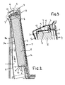
Figure 2 is a cross sectional view along line A-A offigure 1 , and -
Figure 3 is a close up view of the area A offigure 2 . -
Figure 1 is a perspective view of a lower part of vehicle a cab 1a which is fitted withair canals air canals air canals 16 in the direction indicated by arrows X. Air from the cab 1a is also fed to the HVAC system through recirculation ducts 1 in the direction indicated by arrows Y. Air duct 1 is provided with anopening 2 at one end into which afilter 5 is fitted. The other end of the duct 1 is connected to the HVAC system. Air from the cab 1a is drawn throughfilter 5, flows through duct 1 and into the HVAC system. - Air duct 1 may be made from blow moulded plastics material. Air duct 1 could easily be a different duct, such as an air vent, air distributor or fresh air intake and is not restricted for use with a heating/cooling system.
-
Figure 2 is a cross sectional view of the opening offigure 1 along line A-A. - Duct 1 is a hollow member defined by a
wall 4 and manufactured by blow moulding. The part of duct 1 shown infigure 2 can be best described as a closed end cylinder from which a section of thewall 4 has been pushed inwards forming anopening 2 which leads into the duct. A part of thewall 6 around the opening extends into the duct.Wall part 6 may be tapered inwards. A part of wall is removed to form acentral aperture 8a through to duct 1 so that air can pass through theopening 2 and into the duct 1. - Duct 1 is shown with a
filter 5 fitted. Air is drawn throughfilter 5 and flows through the duct 1 as indicated by arrows Y. At an upper part A of the duct 1,wall 4 is of a double layer structure comprising two walls with agap 3 inbetween. Whencentral aperture 8a is formed, element 7 which extends at right angles to thewall part 6 is left behind. Element 7 andwall part 6 form arecess 8 for supportingfilter 5. The recess can be accessed through opening 2.Wall part 6 is the same length as the breadth offilter 5 so that when the filter is in therecess 8 a part of the rear wall 5 a of the filter abuts with element 7 preventing further movement of the filter into the duct 1. - Wall part is provided with a
slot 9 around its perimeter.Filter 5 is provided with a sealing means 10 around its perimeter. Asfilter 5 is pushed into therecess 8, sealing means 10 is pushed throughslot 9 sealing and holding the filter within the recess. Owing to the compression of the sealing means 10 and the friction between the surfaces of the filter and the surfaces defining the recess, the filter is fixed firmly within therecess 8. - A
cover 11 is provided overfilter 5 and is connected towall 4 to protect the filter. - The invention provides a stiff duct which is reinforced towards the upper part A by the double layer structure. Since
wall part 6 extends into the duct the same distance as the breadth of the filter, the duct offers good support to the filter. Element 7 also provides support to the filter and prevents movement of the filer further into the duct. - In the shown embodiment, duct 1 is made by blow-moulding technology. It is envisaged that any other method used to form a hollow plastic part in one manufacturing step, e.g. rotational moulding, may be used.
- The
central aperture 8a defined by element 7 may be rectangular in shape. Element 7 may be provided with stiffening connectors connecting opposing sides of element 7 acrossaperture 8a to strengthen element 7 andwall part 6. - Where the duct 1 is made of a stiff material, element 7 may be reduced in length to increase the size of
aperture 8a. This increases the air flow from thefilter 5 into the duct 1.
Claims (8)
- An air duct (1) comprising a recess (8) for receiving a filter (5), the duct (1) having a wall (4), characterized in that a part (6) of the wall extends into the duct (1) and sait wall part (6) is provided with an element (7) which extends perpendicular to the wall part (6), and wherein said element (7) and said wall part (6) define said recess (8) within the duct for receiving a filter (5), said recess (8) having an aperture through to the duct (1), wherein when a filter (5) is fitted, said element (7) abuts with the filter (5) and said wall part (6) engages with a sealing means (10) associated with the filter (5).
- An air duct (1) as claimed in any preceding claim wherein the part (6) of the wall extending into the duct is the same length as the width of the filter (5).
- An air duct (1) as claimed in any preceding claim wherein the part (6) of the wall extending into the duct is provided with a slot (9) for receiving a sealing means (10) connected to the filter.
- An air duct (1) as claimed in any preceding claim wherein the air duct (1) is made by a single step manufacturing process.
- An air duct (1) as claimed in any preceding claim wherein the air duct (1) is made from blow moulding or rotational moulding.
- An air duct (1) as claimed in any preceding claim wherein the duct (1) is provided with a second wall to reinforce the recess (8).
- An air duct (1) as claimed in claim 6 wherein the recess (8) is provided with a cover (11) and said cover (11) is connected to the wall (4) and/or the second wall of the air duct.
- An air duct (1) as claimed in any preceding claim, wherein said filter (5) is provided with a sealing means (10) around its outer perimeter.
Applications Claiming Priority (1)
| Application Number | Priority Date | Filing Date | Title |
|---|---|---|---|
| GBGB1109699.7A GB201109699D0 (en) | 2011-06-10 | 2011-06-10 | Air duct |
Publications (2)
| Publication Number | Publication Date |
|---|---|
| EP2532542A1 EP2532542A1 (en) | 2012-12-12 |
| EP2532542B1 true EP2532542B1 (en) | 2014-09-24 |
Family
ID=44357491
Family Applications (1)
| Application Number | Title | Priority Date | Filing Date |
|---|---|---|---|
| EP12170418.3A Active EP2532542B1 (en) | 2011-06-10 | 2012-06-01 | Air duct |
Country Status (2)
| Country | Link |
|---|---|
| EP (1) | EP2532542B1 (en) |
| GB (1) | GB201109699D0 (en) |
Families Citing this family (1)
| Publication number | Priority date | Publication date | Assignee | Title |
|---|---|---|---|---|
| GB202019049D0 (en) | 2020-12-03 | 2021-01-20 | Agco Int Gmbh | Air filtration system |
Family Cites Families (4)
| Publication number | Priority date | Publication date | Assignee | Title |
|---|---|---|---|---|
| DE4419626B4 (en) * | 1993-06-26 | 2006-01-26 | Volkswagen Ag | Fresh air supply for the passenger compartment of a motor vehicle |
| JP3572146B2 (en) * | 1996-07-03 | 2004-09-29 | 三菱重工業株式会社 | Vehicle air conditioner |
| DE10151618C1 (en) * | 2001-10-23 | 2003-04-24 | Webasto Thermosysteme Gmbh | Vehicle air-conditioning unit has filter housing with air entry cover on swivel axis for full right-angle swivel to snap home closed with cover condensate chamber-fitted filter |
| DE10249110B4 (en) * | 2002-10-21 | 2006-03-09 | Behr Gmbh & Co. Kg | Filter device, filter element and filter frame |
-
2011
- 2011-06-10 GB GBGB1109699.7A patent/GB201109699D0/en not_active Ceased
-
2012
- 2012-06-01 EP EP12170418.3A patent/EP2532542B1/en active Active
Also Published As
| Publication number | Publication date |
|---|---|
| GB201109699D0 (en) | 2011-07-27 |
| EP2532542A1 (en) | 2012-12-12 |
Similar Documents
| Publication | Publication Date | Title |
|---|---|---|
| EP0932515B2 (en) | A filter device for filtering a fluid | |
| EP2807364B1 (en) | Motor vehicle with improved air intake apparatus | |
| US11223187B2 (en) | Harness protector and harness assembly | |
| CN102627090A (en) | Screening panel for a sensor unit of a motor vehicle | |
| ITMI20120654A1 (en) | VENTILATION ELEMENT OF A CASE CONTAINING AN ELECTRIC, MECHANICAL OR ELECTROMECHANICAL ORGAN | |
| US6422197B1 (en) | Intake system | |
| US20070048138A1 (en) | Fan shroud structure reinforcement to reduce or eliminate warping and distortion | |
| JP2016504771A (en) | Controller enclosure assembly | |
| CN110370918B (en) | Air guide device for vehicle front structure | |
| US9139071B2 (en) | Installation aid for a ventilation nozzle and a ventilation duct of a motor vehicle, ventilation nozzle, ventilation duct, and dashboard | |
| US20180244146A1 (en) | Air flap assembly | |
| US20100127535A1 (en) | External grille device for automotive vehicle | |
| US20180038396A1 (en) | Motor Vehicle | |
| EP2532542A1 (en) | Air duct | |
| US9217400B2 (en) | Intake apparatus | |
| WO2014031994A2 (en) | Fan shroud with complementary two-sided ribbing | |
| JP6062718B2 (en) | Structure of the junction of the ventilation duct | |
| US10583708B2 (en) | Connecting pipe linking a thermal device of a motor vehicle to a firewall of the vehicle | |
| US20180154762A1 (en) | Front end arrangement of a motor vehicle | |
| US10532651B2 (en) | Motor vehicle having an air guide and an air duct | |
| CN204674680U (en) | For structure and the grill-protected of the vehicle with rear-mounted engine | |
| CN100491184C (en) | Motor cycle baffle | |
| KR102146310B1 (en) | Front end module carrier | |
| KR101626325B1 (en) | Serviceability is enhanced Undercover | |
| KR102054971B1 (en) | Air cleaner |
Legal Events
| Date | Code | Title | Description |
|---|---|---|---|
| PUAI | Public reference made under article 153(3) epc to a published international application that has entered the european phase |
Free format text: ORIGINAL CODE: 0009012 |
|
| AK | Designated contracting states |
Kind code of ref document: A1 Designated state(s): AL AT BE BG CH CY CZ DE DK EE ES FI FR GB GR HR HU IE IS IT LI LT LU LV MC MK MT NL NO PL PT RO RS SE SI SK SM TR |
|
| AX | Request for extension of the european patent |
Extension state: BA ME |
|
| 17P | Request for examination filed |
Effective date: 20130612 |
|
| RBV | Designated contracting states (corrected) |
Designated state(s): AL AT BE BG CH CY CZ DE DK EE ES FI FR GB GR HR HU IE IS IT LI LT LU LV MC MK MT NL NO PL PT RO RS SE SI SK SM TR |
|
| 18D | Application deemed to be withdrawn |
Effective date: 20130613 |
|
| D18D | Application deemed to be withdrawn (deleted) | ||
| RIC1 | Information provided on ipc code assigned before grant |
Ipc: B60H 3/06 20060101ALI20140320BHEP Ipc: B60H 1/00 20060101AFI20140320BHEP |
|
| GRAP | Despatch of communication of intention to grant a patent |
Free format text: ORIGINAL CODE: EPIDOSNIGR1 |
|
| INTG | Intention to grant announced |
Effective date: 20140603 |
|
| GRAS | Grant fee paid |
Free format text: ORIGINAL CODE: EPIDOSNIGR3 |
|
| GRAA | (expected) grant |
Free format text: ORIGINAL CODE: 0009210 |
|
| AK | Designated contracting states |
Kind code of ref document: B1 Designated state(s): AL AT BE BG CH CY CZ DE DK EE ES FI FR GB GR HR HU IE IS IT LI LT LU LV MC MK MT NL NO PL PT RO RS SE SI SK SM TR |
|
| REG | Reference to a national code |
Ref country code: CH Ref legal event code: EP |
|
| REG | Reference to a national code |
Ref country code: AT Ref legal event code: REF Ref document number: 688439 Country of ref document: AT Kind code of ref document: T Effective date: 20141015 |
|
| REG | Reference to a national code |
Ref country code: IE Ref legal event code: FG4D |
|
| REG | Reference to a national code |
Ref country code: DE Ref legal event code: R096 Ref document number: 602012003174 Country of ref document: DE Effective date: 20141106 |
|
| PG25 | Lapsed in a contracting state [announced via postgrant information from national office to epo] |
Ref country code: FI Free format text: LAPSE BECAUSE OF FAILURE TO SUBMIT A TRANSLATION OF THE DESCRIPTION OR TO PAY THE FEE WITHIN THE PRESCRIBED TIME-LIMIT Effective date: 20140924 Ref country code: NO Free format text: LAPSE BECAUSE OF FAILURE TO SUBMIT A TRANSLATION OF THE DESCRIPTION OR TO PAY THE FEE WITHIN THE PRESCRIBED TIME-LIMIT Effective date: 20141224 Ref country code: GR Free format text: LAPSE BECAUSE OF FAILURE TO SUBMIT A TRANSLATION OF THE DESCRIPTION OR TO PAY THE FEE WITHIN THE PRESCRIBED TIME-LIMIT Effective date: 20141225 Ref country code: SE Free format text: LAPSE BECAUSE OF FAILURE TO SUBMIT A TRANSLATION OF THE DESCRIPTION OR TO PAY THE FEE WITHIN THE PRESCRIBED TIME-LIMIT Effective date: 20140924 Ref country code: LT Free format text: LAPSE BECAUSE OF FAILURE TO SUBMIT A TRANSLATION OF THE DESCRIPTION OR TO PAY THE FEE WITHIN THE PRESCRIBED TIME-LIMIT Effective date: 20140924 |
|
| REG | Reference to a national code |
Ref country code: LT Ref legal event code: MG4D Ref country code: NL Ref legal event code: VDEP Effective date: 20140924 |
|
| PG25 | Lapsed in a contracting state [announced via postgrant information from national office to epo] |
Ref country code: CY Free format text: LAPSE BECAUSE OF FAILURE TO SUBMIT A TRANSLATION OF THE DESCRIPTION OR TO PAY THE FEE WITHIN THE PRESCRIBED TIME-LIMIT Effective date: 20140924 Ref country code: RS Free format text: LAPSE BECAUSE OF FAILURE TO SUBMIT A TRANSLATION OF THE DESCRIPTION OR TO PAY THE FEE WITHIN THE PRESCRIBED TIME-LIMIT Effective date: 20140924 Ref country code: HR Free format text: LAPSE BECAUSE OF FAILURE TO SUBMIT A TRANSLATION OF THE DESCRIPTION OR TO PAY THE FEE WITHIN THE PRESCRIBED TIME-LIMIT Effective date: 20140924 Ref country code: LV Free format text: LAPSE BECAUSE OF FAILURE TO SUBMIT A TRANSLATION OF THE DESCRIPTION OR TO PAY THE FEE WITHIN THE PRESCRIBED TIME-LIMIT Effective date: 20140924 |
|
| REG | Reference to a national code |
Ref country code: AT Ref legal event code: MK05 Ref document number: 688439 Country of ref document: AT Kind code of ref document: T Effective date: 20140924 |
|
| PG25 | Lapsed in a contracting state [announced via postgrant information from national office to epo] |
Ref country code: NL Free format text: LAPSE BECAUSE OF FAILURE TO SUBMIT A TRANSLATION OF THE DESCRIPTION OR TO PAY THE FEE WITHIN THE PRESCRIBED TIME-LIMIT Effective date: 20140924 |
|
| PG25 | Lapsed in a contracting state [announced via postgrant information from national office to epo] |
Ref country code: SK Free format text: LAPSE BECAUSE OF FAILURE TO SUBMIT A TRANSLATION OF THE DESCRIPTION OR TO PAY THE FEE WITHIN THE PRESCRIBED TIME-LIMIT Effective date: 20140924 Ref country code: EE Free format text: LAPSE BECAUSE OF FAILURE TO SUBMIT A TRANSLATION OF THE DESCRIPTION OR TO PAY THE FEE WITHIN THE PRESCRIBED TIME-LIMIT Effective date: 20140924 Ref country code: CZ Free format text: LAPSE BECAUSE OF FAILURE TO SUBMIT A TRANSLATION OF THE DESCRIPTION OR TO PAY THE FEE WITHIN THE PRESCRIBED TIME-LIMIT Effective date: 20140924 Ref country code: ES Free format text: LAPSE BECAUSE OF FAILURE TO SUBMIT A TRANSLATION OF THE DESCRIPTION OR TO PAY THE FEE WITHIN THE PRESCRIBED TIME-LIMIT Effective date: 20140924 Ref country code: IS Free format text: LAPSE BECAUSE OF FAILURE TO SUBMIT A TRANSLATION OF THE DESCRIPTION OR TO PAY THE FEE WITHIN THE PRESCRIBED TIME-LIMIT Effective date: 20150124 Ref country code: PT Free format text: LAPSE BECAUSE OF FAILURE TO SUBMIT A TRANSLATION OF THE DESCRIPTION OR TO PAY THE FEE WITHIN THE PRESCRIBED TIME-LIMIT Effective date: 20150126 |
|
| PG25 | Lapsed in a contracting state [announced via postgrant information from national office to epo] |
Ref country code: PL Free format text: LAPSE BECAUSE OF FAILURE TO SUBMIT A TRANSLATION OF THE DESCRIPTION OR TO PAY THE FEE WITHIN THE PRESCRIBED TIME-LIMIT Effective date: 20140924 Ref country code: AT Free format text: LAPSE BECAUSE OF FAILURE TO SUBMIT A TRANSLATION OF THE DESCRIPTION OR TO PAY THE FEE WITHIN THE PRESCRIBED TIME-LIMIT Effective date: 20140924 |
|
| REG | Reference to a national code |
Ref country code: FR Ref legal event code: PLFP Year of fee payment: 4 |
|
| REG | Reference to a national code |
Ref country code: DE Ref legal event code: R097 Ref document number: 602012003174 Country of ref document: DE |
|
| PG25 | Lapsed in a contracting state [announced via postgrant information from national office to epo] |
Ref country code: DK Free format text: LAPSE BECAUSE OF FAILURE TO SUBMIT A TRANSLATION OF THE DESCRIPTION OR TO PAY THE FEE WITHIN THE PRESCRIBED TIME-LIMIT Effective date: 20140924 |
|
| PLBE | No opposition filed within time limit |
Free format text: ORIGINAL CODE: 0009261 |
|
| STAA | Information on the status of an ep patent application or granted ep patent |
Free format text: STATUS: NO OPPOSITION FILED WITHIN TIME LIMIT |
|
| 26N | No opposition filed |
Effective date: 20150625 |
|
| PG25 | Lapsed in a contracting state [announced via postgrant information from national office to epo] |
Ref country code: MC Free format text: LAPSE BECAUSE OF FAILURE TO SUBMIT A TRANSLATION OF THE DESCRIPTION OR TO PAY THE FEE WITHIN THE PRESCRIBED TIME-LIMIT Effective date: 20140924 |
|
| REG | Reference to a national code |
Ref country code: CH Ref legal event code: PL |
|
| PG25 | Lapsed in a contracting state [announced via postgrant information from national office to epo] |
Ref country code: SI Free format text: LAPSE BECAUSE OF FAILURE TO SUBMIT A TRANSLATION OF THE DESCRIPTION OR TO PAY THE FEE WITHIN THE PRESCRIBED TIME-LIMIT Effective date: 20140924 Ref country code: LU Free format text: LAPSE BECAUSE OF FAILURE TO SUBMIT A TRANSLATION OF THE DESCRIPTION OR TO PAY THE FEE WITHIN THE PRESCRIBED TIME-LIMIT Effective date: 20150601 |
|
| REG | Reference to a national code |
Ref country code: IE Ref legal event code: MM4A |
|
| PG25 | Lapsed in a contracting state [announced via postgrant information from national office to epo] |
Ref country code: IE Free format text: LAPSE BECAUSE OF NON-PAYMENT OF DUE FEES Effective date: 20150601 Ref country code: LI Free format text: LAPSE BECAUSE OF NON-PAYMENT OF DUE FEES Effective date: 20150630 Ref country code: CH Free format text: LAPSE BECAUSE OF NON-PAYMENT OF DUE FEES Effective date: 20150630 |
|
| REG | Reference to a national code |
Ref country code: FR Ref legal event code: PLFP Year of fee payment: 5 |
|
| PG25 | Lapsed in a contracting state [announced via postgrant information from national office to epo] |
Ref country code: MT Free format text: LAPSE BECAUSE OF FAILURE TO SUBMIT A TRANSLATION OF THE DESCRIPTION OR TO PAY THE FEE WITHIN THE PRESCRIBED TIME-LIMIT Effective date: 20140924 |
|
| PG25 | Lapsed in a contracting state [announced via postgrant information from national office to epo] |
Ref country code: BG Free format text: LAPSE BECAUSE OF FAILURE TO SUBMIT A TRANSLATION OF THE DESCRIPTION OR TO PAY THE FEE WITHIN THE PRESCRIBED TIME-LIMIT Effective date: 20140924 Ref country code: SM Free format text: LAPSE BECAUSE OF FAILURE TO SUBMIT A TRANSLATION OF THE DESCRIPTION OR TO PAY THE FEE WITHIN THE PRESCRIBED TIME-LIMIT Effective date: 20140924 Ref country code: RO Free format text: LAPSE BECAUSE OF FAILURE TO SUBMIT A TRANSLATION OF THE DESCRIPTION OR TO PAY THE FEE WITHIN THE PRESCRIBED TIME-LIMIT Effective date: 20140924 Ref country code: HU Free format text: LAPSE BECAUSE OF FAILURE TO SUBMIT A TRANSLATION OF THE DESCRIPTION OR TO PAY THE FEE WITHIN THE PRESCRIBED TIME-LIMIT; INVALID AB INITIO Effective date: 20120601 |
|
| REG | Reference to a national code |
Ref country code: FR Ref legal event code: PLFP Year of fee payment: 6 |
|
| PG25 | Lapsed in a contracting state [announced via postgrant information from national office to epo] |
Ref country code: TR Free format text: LAPSE BECAUSE OF FAILURE TO SUBMIT A TRANSLATION OF THE DESCRIPTION OR TO PAY THE FEE WITHIN THE PRESCRIBED TIME-LIMIT Effective date: 20140924 |
|
| PG25 | Lapsed in a contracting state [announced via postgrant information from national office to epo] |
Ref country code: BE Free format text: LAPSE BECAUSE OF FAILURE TO SUBMIT A TRANSLATION OF THE DESCRIPTION OR TO PAY THE FEE WITHIN THE PRESCRIBED TIME-LIMIT Effective date: 20140924 |
|
| REG | Reference to a national code |
Ref country code: FR Ref legal event code: PLFP Year of fee payment: 7 |
|
| PG25 | Lapsed in a contracting state [announced via postgrant information from national office to epo] |
Ref country code: MK Free format text: LAPSE BECAUSE OF FAILURE TO SUBMIT A TRANSLATION OF THE DESCRIPTION OR TO PAY THE FEE WITHIN THE PRESCRIBED TIME-LIMIT Effective date: 20140924 |
|
| PG25 | Lapsed in a contracting state [announced via postgrant information from national office to epo] |
Ref country code: AL Free format text: LAPSE BECAUSE OF FAILURE TO SUBMIT A TRANSLATION OF THE DESCRIPTION OR TO PAY THE FEE WITHIN THE PRESCRIBED TIME-LIMIT Effective date: 20140924 |
|
| PGFP | Annual fee paid to national office [announced via postgrant information from national office to epo] |
Ref country code: FI Payment date: 20190416 Year of fee payment: 8 |
|
| PG25 | Lapsed in a contracting state [announced via postgrant information from national office to epo] |
Ref country code: IT Free format text: LAPSE BECAUSE OF NON-PAYMENT OF DUE FEES Effective date: 20200601 |
|
| P01 | Opt-out of the competence of the unified patent court (upc) registered |
Effective date: 20230518 |
|
| PGFP | Annual fee paid to national office [announced via postgrant information from national office to epo] |
Ref country code: DE Payment date: 20250618 Year of fee payment: 14 |
|
| PGFP | Annual fee paid to national office [announced via postgrant information from national office to epo] |
Ref country code: GB Payment date: 20250618 Year of fee payment: 14 |
|
| PGFP | Annual fee paid to national office [announced via postgrant information from national office to epo] |
Ref country code: FR Payment date: 20250624 Year of fee payment: 14 |