EP2532473A1 - Sealing system and sealing method - Google Patents
Sealing system and sealing method Download PDFInfo
- Publication number
- EP2532473A1 EP2532473A1 EP12166559A EP12166559A EP2532473A1 EP 2532473 A1 EP2532473 A1 EP 2532473A1 EP 12166559 A EP12166559 A EP 12166559A EP 12166559 A EP12166559 A EP 12166559A EP 2532473 A1 EP2532473 A1 EP 2532473A1
- Authority
- EP
- European Patent Office
- Prior art keywords
- workpiece
- fluid
- seal material
- opening hole
- tubular part
- Prior art date
- Legal status (The legal status is an assumption and is not a legal conclusion. Google has not performed a legal analysis and makes no representation as to the accuracy of the status listed.)
- Withdrawn
Links
- 238000007789 sealing Methods 0.000 title claims abstract description 31
- 238000000034 method Methods 0.000 title claims abstract description 12
- 239000012530 fluid Substances 0.000 claims abstract description 31
- 239000000463 material Substances 0.000 claims abstract description 31
- 238000005086 pumping Methods 0.000 claims abstract description 17
- 238000003780 insertion Methods 0.000 claims description 5
- 230000037431 insertion Effects 0.000 claims description 5
- 230000005489 elastic deformation Effects 0.000 description 4
- 238000003825 pressing Methods 0.000 description 3
- 238000004519 manufacturing process Methods 0.000 description 2
- 239000002184 metal Substances 0.000 description 1
- 230000003746 surface roughness Effects 0.000 description 1
Images

Classifications
-
- B—PERFORMING OPERATIONS; TRANSPORTING
- B23—MACHINE TOOLS; METAL-WORKING NOT OTHERWISE PROVIDED FOR
- B23P—METAL-WORKING NOT OTHERWISE PROVIDED FOR; COMBINED OPERATIONS; UNIVERSAL MACHINE TOOLS
- B23P9/00—Treating or finishing surfaces mechanically, with or without calibrating, primarily to resist wear or impact, e.g. smoothing or roughening turbine blades or bearings; Features of such surfaces not otherwise provided for, their treatment being unspecified
-
- C—CHEMISTRY; METALLURGY
- C21—METALLURGY OF IRON
- C21D—MODIFYING THE PHYSICAL STRUCTURE OF FERROUS METALS; GENERAL DEVICES FOR HEAT TREATMENT OF FERROUS OR NON-FERROUS METALS OR ALLOYS; MAKING METAL MALLEABLE, e.g. BY DECARBURISATION OR TEMPERING
- C21D7/00—Modifying the physical properties of iron or steel by deformation
- C21D7/02—Modifying the physical properties of iron or steel by deformation by cold working
- C21D7/10—Modifying the physical properties of iron or steel by deformation by cold working of the whole cross-section, e.g. of concrete reinforcing bars
- C21D7/12—Modifying the physical properties of iron or steel by deformation by cold working of the whole cross-section, e.g. of concrete reinforcing bars by expanding tubular bodies
-
- F—MECHANICAL ENGINEERING; LIGHTING; HEATING; WEAPONS; BLASTING
- F02—COMBUSTION ENGINES; HOT-GAS OR COMBUSTION-PRODUCT ENGINE PLANTS
- F02M—SUPPLYING COMBUSTION ENGINES IN GENERAL WITH COMBUSTIBLE MIXTURES OR CONSTITUENTS THEREOF
- F02M55/00—Fuel-injection apparatus characterised by their fuel conduits or their venting means; Arrangements of conduits between fuel tank and pump F02M37/00
- F02M55/02—Conduits between injection pumps and injectors, e.g. conduits between pump and common-rail or conduits between common-rail and injectors
- F02M55/025—Common rails
-
- F—MECHANICAL ENGINEERING; LIGHTING; HEATING; WEAPONS; BLASTING
- F02—COMBUSTION ENGINES; HOT-GAS OR COMBUSTION-PRODUCT ENGINE PLANTS
- F02M—SUPPLYING COMBUSTION ENGINES IN GENERAL WITH COMBUSTIBLE MIXTURES OR CONSTITUENTS THEREOF
- F02M2200/00—Details of fuel-injection apparatus, not otherwise provided for
- F02M2200/80—Fuel injection apparatus manufacture, repair or assembly
- F02M2200/8053—Fuel injection apparatus manufacture, repair or assembly involving mechanical deformation of the apparatus or parts thereof
Definitions
- the present invention relates to a sealing system and sealing method which suppress leakage of high pressure fluid from the inside of a workpiece.
- Autofrettage is processing which seals a workpiece and applies a high inside pressure in that state so as to leave residual stress in the structure of the workpiece and thereby raise the strength.
- a sealing system has to be used.
- WO2008/05849 discloses one example of a sealing system which seals a workpiece by pressing a cone-shaped sealing tip against the opening edge of the workpiece.
- a seal material is press-fit in the opening hole of the workpiece so as to seal the hole, the seal material which is inserted into the opening hole of the workpiece is made to expand inside of the workpiece by pressing so as to cause the hole to be sealed tight, or other means may be considered.
- the seal material ends up plastically deforming, so the seal material cannot be repeatedly used.
- the present invention in consideration of the above point, provides a sealing system and sealing method which enable repeated use of the seal material which is inserted inside of the workpiece.
- a sealing system which is provided with a pumping means (11) for pumping a fluid to the inside of the workpiece (1), a seal material (12) which is inserted into an opening hole (1a) of the workpiece (1) and which suppresses leakage of the fluid from the opening hole (1a), and a detachment preventing means (13, 14) for preventing the seal material (12) from detaching from the opening hole (1a), wherein the seal material (12) has a tubular part (12a) which opens at a front end side which is inserted into the opening hole (1a), and the tubular part (12a) is formed so as to elastically deform in an expanding direction when the inside pressure at the inside of the workpiece (1) rises due to pumping of the fluid.
- the tubular part (12a) of the seal material (12) deforms in an expanding direction, so the seal material (12) which is inserted to the inside of the workpiece (1) can suppress leakage of fluid. Furthermore, the deformation of the seal material (12) is elastic deformation, so the seal material (12) can be repeatedly used.
- an inside wall surface of the tubular part (12a) is provided with a rounded shape for avoiding stress concentration.
- the aspect of the invention characterized in that the tubular part (12a) is provided with a thin part (12b) for facilitating expansion due to the inside pressure at the inside of the workpiece (1).
- tubular part (12a) is provided with a tapered part (12c) for facilitating insertion into the opening hole (1a).
- the aspect of the invention characterized in that the outer circumference of the seal material (12) is provided with a roughened part (12d) for making the flow resistance of the fluid increase.
- a sealing method which uses the aspect of the invention which is described in any one of claims 1 to 5 characterized by comprising a step of inserting said seal material (12) into said opening hole (1a), a step of pumping means (11), while preventing said seal material (12) from detaching from said opening hole (1a) by said detachment preventing means (13, 14), and a step of raising the inside pressure at the inside of said workpiece (1) and deforming said tubular part (12a) elastically in an expanding direction of said tubular part (12a) by pumping of said fluid.
- the present invention can also be viewed as an invention of an autofrettage system and an autofrettage method. Further, the present invention can also be viewed as an invention of a system for manufacture of a common rail and a method of manufacture of a common rail.
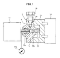
- FIG. 1 is a cross-sectional view which shows an autofrettage system in a first embodiment.
- a workpiece 1 has a straight through hole 1a (opening hole) and a horizontal hole 1b which perpendicularly intersects the through hole 1a.
- the through hole 1a and the horizontal hole 1b are circular in cross-sectional shapes.
- the autofrettage system is a system for autofrettage of the workpiece 1 and is provided with a high pressure pump 11, a seal pin 12, a seal pin holder 13, a hydraulic cylinder 14, and a cap 15.
- the high pressure pump 11 is a pumping means for pumping autofrettage fluid (working oil) to the inside of a workpiece 1 and has a discharge nozzle 11a which may be inserted into one end of the through hole 1a of the workpiece 1 (left end in FIG. 1 ).
- the discharge nozzle 11a is formed with a tapered part or a stepped part.
- the tapered part or stepped part of the discharge nozzle 11a is designed to abut against a tapered part or stepped part which is formed at the through hole 1a of the workpiece 1.
- the pressure of the autofrettage fluid which the high pressure pump 11 pumps is designed to be measured by a manometer 11b.
- the seal pin 12 is a seal material which suppresses leakage of autofrettage fluid from the other end of the through hole 1a of the workpiece 1 (right end in FIG. 1 ) and is inserted into the other end of the through hole 1a.
- the seal pin 12 is formed by a metal.
- the outside diameter of the seal pin 12 is preferably the same as the inside diameter of the through hole 1a of the workpiece 1, but variation (error) in processing of the through hole 1a of the workpiece 1 is unavoidable, so the outside diameter of the seal pin 12 is designed to be just a bit smaller than the inside diameter of the through hole 1a of the workpiece 1.
- the seal pin 12 has a tubular part 12a which opens toward the front end side of insertion (left end side of FIG. 1 ).
- the tubular part 12a is formed so as to elastically deform in the direction expanding outward in the diametrical direction when the inside pressure of the workpiece 1 rises due to pumping of the autofrettage fluid (i.e., in the direction closely contacting inner wall of through hole 1a).
- the seal pin holder 13 and hydraulic cylinder 14 are detachment preventing means for preventing the seal pin 12 from detaching from the through hole 1a of the workpiece 1.
- the seal pin holder 13 is arranged so as to plug the through hole 1a.
- the hydraulic cylinder 14 pushes the seal pin holder 13 to the workpiece 1 side. By the hydraulic cylinder 14 pushing the seal pin holder 13, the workpiece 1 is pushed against the discharge nozzle 11a.
- the cap 15 suppresses leakage of the autofrettage fluid from the horizontal hole 1b of the workpiece 1. Specifically, the cap 15 is cut with a male thread and is formed with a tapered part or a stepped part. The male thread of the cap 15 is fastened with a female thread of the horizontal hole 1b. As a result, the tapered part or the stepped part of the cap 15 is pressed against the tapered part or stepped part of the horizontal hole 1b for sealing. The front end of the cap 15 may also be sealed by pressing a ball against the tapered part of the horizontal hole 1b.
- the seal pin 12 is set (inserted) into the through hole 1a of the workpiece 1, then the workpiece 1 is set between the high pressure pump 11 and the seal pin holder 13.
- the discharge nozzle 11a of the high pressure pump 11 is inserted into one end of the through hole 1a of the workpiece 11, the seal pin holder 13 closes the other end of the through hole 1a of the workpiece 1, and the hydraulic cylinder 14 presses down the seal pin holder 13.
- the high pressure pump 11 is used to pump the autofrettage fluid to the inside of the workpiece 1.
- the slight clearance present between the outer circumference of the seal pin 12 and the inner circumference of through hole 1a of the workpiece 1 leaks autofrettage fluid, but by feeding the autofrettage fluid faster than the leakage from the clearance, the inside pressure of the workpiece 1 can be made to rise.
- This feed rate of the autofrettage fluid can be calculated from the dimensions of the clearance between the seal pin 12 and through hole 1a, the viscosity of the autofrettage fluid, etc.
- the high pressure pump 11 When the inside pressure of the workpiece 1 rises to a predetermined pressure which is required for autofrettage (for example, an ultrahigh pressure of 500 MPa or more), the high pressure pump 11 is operated in reverse to make the inside pressure drop. After the drop of the inside pressure, the seal pin 12 returns to its original shape. In this way, the workpiece 1 can be processed by autofrettage.
- a predetermined pressure which is required for autofrettage for example, an ultrahigh pressure of 500 MPa or more
- the tubular part 12a of the seal pin 12 deforms in an expanding direction, so the seal pin 12 which is inserted inside of the workpiece 1 can be used to suppress leakage of the autofrettage fluid. Furthermore, the deformation of the seal pin 12 is elastic deformation, so the seal pin 12 can be repeatedly used.
- the seal pin 12 can be freely set in sealing position inside of the workpiece so long as it is able to be inserted into the inside of the workpiece 1. For this reason, parts with sections which are weak strengthwise or parts from which high precision is demanded can be easily processed by autofrettage since the sealing position can be suitably set inside of the workpiece.
- the tubular part 12a of the seal pin 12 is made a shape which is easy to deform and is durable. Specifically, as shown in FIG. 3 , the inner wall surface of the tubular part 12a of the seal pin 12 is rounded to avoid stress concentration. Further, the tubular part 12a of the seal pin 12 is formed with a thin part 12b to enable easy expansion.
- the seal pin 12 is shaped for easy insertion into the through hole 1a even if the clearance with the through hole 1a is extremely small. Specifically, as shown in FIG. 4 , the frontmost end of the tubular part 12a of the seal pin 12 is formed with a tapered part 12c to facilitate insertion into the through hole 1a.
- the shape of the seal pin 12 is set so that before the seal pin 12 elastically deforms, the autofrettage fluid does not easily flow into the clearance with the through hole 1a.
- the outer circumference of the seal pin 12 is formed with a roughened part 12d with large surface roughness.
- the roughened part 12d cause an increase in the flow resistance of the autofrettage fluid at the clearance, so it is possible to promote a rise in the inside pressure of the workpiece 1 and reliably enable elastic deformation of the seal pin 12.
Landscapes
- Engineering & Computer Science (AREA)
- Chemical & Material Sciences (AREA)
- Mechanical Engineering (AREA)
- Combustion & Propulsion (AREA)
- General Engineering & Computer Science (AREA)
- Crystallography & Structural Chemistry (AREA)
- Materials Engineering (AREA)
- Metallurgy (AREA)
- Organic Chemistry (AREA)
- Gasket Seals (AREA)
- Shaping Metal By Deep-Drawing, Or The Like (AREA)
Abstract
A sealing system which is provided with a pumping means (11) for pumping a fluid to the inside of a workpiece (1), a seal material (12) which is inserted into an opening hole (1a) of the workpiece (1) and which suppresses leakage of the fluid from the opening hole (1a), and detachment preventing means (13,14) for preventing the seal material (12) from detaching from the opening hole (1a), wherein the seal material (12) has a tubular part (12a) which opens at a front end side which is inserted into the opening hole (1a), and the tubular part (12a) is formed so as to elastically deform in an expanding direction when the inside pressure at the inside of the workpiece (1) rises due to pumping of the fluid, and a sealing method using the same.
Description
- The present invention relates to a sealing system and sealing method which suppress leakage of high pressure fluid from the inside of a workpiece.
- In recent years, demand has arisen for autofrettage of various pressure resistant parts. "Autofrettage" is processing which seals a workpiece and applies a high inside pressure in that state so as to leave residual stress in the structure of the workpiece and thereby raise the strength. At the time of autofrettage, a sealing system has to be used.
WO2008/05849 - However, in the related art of the above
WO2008/058494 , the opening edge of the workpiece becomes the sealing position, so the range to which the inside pressure is applied ends up becoming broader. As a result, parts with insufficient strength fracture due to the inside pressure, the processing precision ends up deviating from the demanded dimensional precision, and other such trouble easily occur. - When setting the sealing position at the inside of the workpiece, a seal material is press-fit in the opening hole of the workpiece so as to seal the hole, the seal material which is inserted into the opening hole of the workpiece is made to expand inside of the workpiece by pressing so as to cause the hole to be sealed tight, or other means may be considered. When using these means, the seal material ends up plastically deforming, so the seal material cannot be repeatedly used.
- The present invention, in consideration of the above point, provides a sealing system and sealing method which enable repeated use of the seal material which is inserted inside of the workpiece.
- To achieve the above object, in the aspect of the invention which is described in
claim 1, there is provided a sealing system which is provided with a pumping means (11) for pumping a fluid to the inside of the workpiece (1), a seal material (12) which is inserted into an opening hole (1a) of the workpiece (1) and which suppresses leakage of the fluid from the opening hole (1a), and a detachment preventing means (13, 14) for preventing the seal material (12) from detaching from the opening hole (1a), wherein the seal material (12) has a tubular part (12a) which opens at a front end side which is inserted into the opening hole (1a), and the tubular part (12a) is formed so as to elastically deform in an expanding direction when the inside pressure at the inside of the workpiece (1) rises due to pumping of the fluid. - According to this, if the inside pressure of the workpiece (1) rises, the tubular part (12a) of the seal material (12) deforms in an expanding direction, so the seal material (12) which is inserted to the inside of the workpiece (1) can suppress leakage of fluid. Furthermore, the deformation of the seal material (12) is elastic deformation, so the seal material (12) can be repeatedly used.
- In the aspect of the invention which is described in
claim 2, there is provided the aspect of the invention characterized in that an inside wall surface of the tubular part (12a) is provided with a rounded shape for avoiding stress concentration. - Due to this, the durability of the seal material (12) with respect to inside pressure can be raised.
- In the aspect of the invention which is described in claim 3, there is provided the aspect of the invention characterized in that the tubular part (12a) is provided with a thin part (12b) for facilitating expansion due to the inside pressure at the inside of the workpiece (1).
- Due to this, the sealing ability of the seal material (12) can be improved.
- In the aspect of the invention which is described in claim 4, there is provided the aspect of the invention characterized in that tubular part (12a) is provided with a tapered part (12c) for facilitating insertion into the opening hole (1a).
- Due to this, even if the clearance between the seal material (12) and the opening hole (1a) is made small, it is possible to keep the seal material (12) from becoming hard to insert into the opening hole (1a).
- In the aspect of the invention which is described in claim 5, there is provided the aspect of the invention characterized in that the outer circumference of the seal material (12) is provided with a roughened part (12d) for making the flow resistance of the fluid increase.
- Due to this, it is possible to keep fluid from flowing into the clearance with the opening hole (1a) before the seal material (12) elastically deforms, so it is possible to promote a rise in the inside pressure of the workpiece (1) so as to enable reliable elastic deformation of the seal material (12).
- In the aspect of the invention which is described in claim 6, there is provided a sealing method which uses the aspect of the invention which is described in any one of
claims 1 to 5 characterized by comprising a step of inserting said seal material (12) into said opening hole (1a), a step of pumping means (11), while preventing said seal material (12) from detaching from said opening hole (1a) by said detachment preventing means (13, 14), and a step of raising the inside pressure at the inside of said workpiece (1) and deforming said tubular part (12a) elastically in an expanding direction of said tubular part (12a) by pumping of said fluid. - In the above, the explanation was given of the case of viewing the present invention as an invention of a sealing system and a sealing method, but the present invention can also be viewed as an invention of an autofrettage system and an autofrettage method. Further, the present invention can also be viewed as an invention of a system for manufacture of a common rail and a method of manufacture of a common rail.
-
FIG. 1 is a cross-sectional view which shows an autofrettage system in a first embodiment. -
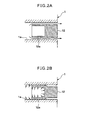
FIGS. 2A and 2B are cross-sectional views which explain a process of autofrettage in the first embodiment. -
FIG. 3 is a cross-sectional view of a seal pin in a second embodiment. -
FIG. 4 is a cross-sectional view of a seal pin in a third embodiment. -
FIG. 5 is a cross-sectional view of a seal pin in a fourth embodiment. - Below, a first embodiment will be explained. In the present embodiment, the example of autofrettage of a component of a common rail which is used in a diesel engine will be explained.
- A
workpiece 1 has a straight throughhole 1a (opening hole) and ahorizontal hole 1b which perpendicularly intersects the throughhole 1a. In the present example, thethrough hole 1a and thehorizontal hole 1b are circular in cross-sectional shapes. - The autofrettage system is a system for autofrettage of the
workpiece 1 and is provided with ahigh pressure pump 11, aseal pin 12, aseal pin holder 13, ahydraulic cylinder 14, and acap 15. - The
high pressure pump 11 is a pumping means for pumping autofrettage fluid (working oil) to the inside of aworkpiece 1 and has adischarge nozzle 11a which may be inserted into one end of the throughhole 1a of the workpiece 1 (left end inFIG. 1 ). - The
discharge nozzle 11a is formed with a tapered part or a stepped part. The tapered part or stepped part of thedischarge nozzle 11a is designed to abut against a tapered part or stepped part which is formed at thethrough hole 1a of theworkpiece 1. - The pressure of the autofrettage fluid which the
high pressure pump 11 pumps is designed to be measured by amanometer 11b. - The
seal pin 12 is a seal material which suppresses leakage of autofrettage fluid from the other end of the throughhole 1a of the workpiece 1 (right end inFIG. 1 ) and is inserted into the other end of the throughhole 1a. In this example, theseal pin 12 is formed by a metal. - The outside diameter of the
seal pin 12 is preferably the same as the inside diameter of the throughhole 1a of theworkpiece 1, but variation (error) in processing of the throughhole 1a of theworkpiece 1 is unavoidable, so the outside diameter of theseal pin 12 is designed to be just a bit smaller than the inside diameter of the throughhole 1a of theworkpiece 1. - The
seal pin 12 has atubular part 12a which opens toward the front end side of insertion (left end side ofFIG. 1 ). Thetubular part 12a is formed so as to elastically deform in the direction expanding outward in the diametrical direction when the inside pressure of theworkpiece 1 rises due to pumping of the autofrettage fluid (i.e., in the direction closely contacting inner wall of throughhole 1a). - The
seal pin holder 13 andhydraulic cylinder 14 are detachment preventing means for preventing theseal pin 12 from detaching from the throughhole 1a of theworkpiece 1. Theseal pin holder 13 is arranged so as to plug the throughhole 1a. Thehydraulic cylinder 14 pushes theseal pin holder 13 to theworkpiece 1 side. By thehydraulic cylinder 14 pushing theseal pin holder 13, theworkpiece 1 is pushed against thedischarge nozzle 11a. - The
cap 15 suppresses leakage of the autofrettage fluid from thehorizontal hole 1b of theworkpiece 1. Specifically, thecap 15 is cut with a male thread and is formed with a tapered part or a stepped part. The male thread of thecap 15 is fastened with a female thread of thehorizontal hole 1b. As a result, the tapered part or the stepped part of thecap 15 is pressed against the tapered part or stepped part of thehorizontal hole 1b for sealing. The front end of thecap 15 may also be sealed by pressing a ball against the tapered part of thehorizontal hole 1b. - Next, an autofrettage method using the above autofrettage system (sealing method) will be explained. First, the
horizontal hole 1b of theworkpiece 1 is closed by thecap 15. Due to this, thehorizontal hole 1b of theworkpiece 1 is sealed utilizing the tapered part or the stepped part. - Next, the
seal pin 12 is set (inserted) into the throughhole 1a of theworkpiece 1, then theworkpiece 1 is set between thehigh pressure pump 11 and theseal pin holder 13. Thedischarge nozzle 11a of thehigh pressure pump 11 is inserted into one end of the throughhole 1a of theworkpiece 11, theseal pin holder 13 closes the other end of the throughhole 1a of theworkpiece 1, and thehydraulic cylinder 14 presses down theseal pin holder 13. - Next, the
high pressure pump 11 is used to pump the autofrettage fluid to the inside of theworkpiece 1. At this time, as shown inFIG. 2A , the slight clearance present between the outer circumference of theseal pin 12 and the inner circumference of throughhole 1a of theworkpiece 1 leaks autofrettage fluid, but by feeding the autofrettage fluid faster than the leakage from the clearance, the inside pressure of theworkpiece 1 can be made to rise. This feed rate of the autofrettage fluid can be calculated from the dimensions of the clearance between theseal pin 12 and throughhole 1a, the viscosity of the autofrettage fluid, etc. - Due to the rise in the inside pressure of the
workpiece 1, as shown inFIG. 2B , a pressure difference arises between the inside and the outside of theseal pin 12. Due to this pressure difference, thetubular part 12a of theseal pin 12 elastically deforms in an expanding direction whereby it closely contacts the inner circumference of the throughhole 1a of theworkpiece 1. Due to this, the flow of the autofrettage fluid is stemmed and a sufficient seal is obtained. - When the inside pressure of the
workpiece 1 rises to a predetermined pressure which is required for autofrettage (for example, an ultrahigh pressure of 500 MPa or more), thehigh pressure pump 11 is operated in reverse to make the inside pressure drop. After the drop of the inside pressure, theseal pin 12 returns to its original shape. In this way, theworkpiece 1 can be processed by autofrettage. - According to the present embodiment, if the inside pressure of the
workpiece 1 rises, thetubular part 12a of theseal pin 12 deforms in an expanding direction, so theseal pin 12 which is inserted inside of theworkpiece 1 can be used to suppress leakage of the autofrettage fluid. Furthermore, the deformation of theseal pin 12 is elastic deformation, so theseal pin 12 can be repeatedly used. - The
seal pin 12 can be freely set in sealing position inside of the workpiece so long as it is able to be inserted into the inside of theworkpiece 1. For this reason, parts with sections which are weak strengthwise or parts from which high precision is demanded can be easily processed by autofrettage since the sealing position can be suitably set inside of the workpiece. - In the second embodiment, the
tubular part 12a of theseal pin 12 is made a shape which is easy to deform and is durable. Specifically, as shown inFIG. 3 , the inner wall surface of thetubular part 12a of theseal pin 12 is rounded to avoid stress concentration. Further, thetubular part 12a of theseal pin 12 is formed with athin part 12b to enable easy expansion. - In this third embodiment, the
seal pin 12 is shaped for easy insertion into the throughhole 1a even if the clearance with the throughhole 1a is extremely small. Specifically, as shown inFIG. 4 , the frontmost end of thetubular part 12a of theseal pin 12 is formed with atapered part 12c to facilitate insertion into the throughhole 1a. - In this fourth embodiment, the shape of the
seal pin 12 is set so that before theseal pin 12 elastically deforms, the autofrettage fluid does not easily flow into the clearance with the throughhole 1a. Specifically, as shown inFIG. 5 , the outer circumference of theseal pin 12 is formed with aroughened part 12d with large surface roughness. - According to this, the roughened
part 12d cause an increase in the flow resistance of the autofrettage fluid at the clearance, so it is possible to promote a rise in the inside pressure of theworkpiece 1 and reliably enable elastic deformation of theseal pin 12. - Note that the above embodiments may be suitably combined.
- Further, in the above embodiments, the explanation was given with reference to an example of application of the present invention to sealing when performing autofrettage on a component of a common rail, but the invention is not limited to this. The present invention can be widely applied to sealing of various workpieces.
Claims (6)
1.
A sealing system which is provided with
a pumping means (11) for pumping a fluid to the inside of the workpiece (1),
a seal material (12) which is inserted into an opening hole (1a) of said workpiece (1) and which suppresses leakage of said fluid from said opening hole (1a), and
detachment preventing means (13, 14) for preventing said seal material (12) from detaching from said opening hole (1a), wherein
said seal material (12) has a tubular part (12a) which opens at a front end side which is inserted into said opening hole (1a), and
said tubular part (12a) is formed so as to elastically deform in an expanding direction when the inside pressure at the inside of said workpiece (1) rises due to pumping of said fluid.
A sealing system which is provided with
a pumping means (11) for pumping a fluid to the inside of the workpiece (1),
a seal material (12) which is inserted into an opening hole (1a) of said workpiece (1) and which suppresses leakage of said fluid from said opening hole (1a), and
detachment preventing means (13, 14) for preventing said seal material (12) from detaching from said opening hole (1a), wherein
said seal material (12) has a tubular part (12a) which opens at a front end side which is inserted into said opening hole (1a), and
said tubular part (12a) is formed so as to elastically deform in an expanding direction when the inside pressure at the inside of said workpiece (1) rises due to pumping of said fluid.
2.
A sealing system as set forth in claim 1 characterized in that an inside wall surface of the tubular part (12a) is provided with a rounded shape for avoiding stress concentration.
A sealing system as set forth in claim 1 characterized in that an inside wall surface of the tubular part (12a) is provided with a rounded shape for avoiding stress concentration.
3.
A sealing system as set forth in claim 1 or 2 characterized in that the tubular part (12a) is provided with a thin part (12b) for facilitating expansion due to the inside pressure at the inside of the workpiece (1).
A sealing system as set forth in claim 1 or 2 characterized in that the tubular part (12a) is provided with a thin part (12b) for facilitating expansion due to the inside pressure at the inside of the workpiece (1).
4.
A sealing system as set forth in any one of claims 1 to 3 characterized in that the tubular part (12a) is provided with a tapered part (12c) for facilitating insertion into said opening hole (1a).
A sealing system as set forth in any one of claims 1 to 3 characterized in that the tubular part (12a) is provided with a tapered part (12c) for facilitating insertion into said opening hole (1a).
5.
A sealing system as set forth in any one of claims 1 to 4 characterized in that the outer circumference of the seal material (12) is provided with a roughened part (12d) for making the flow resistance of the fluid increase.
A sealing system as set forth in any one of claims 1 to 4 characterized in that the outer circumference of the seal material (12) is provided with a roughened part (12d) for making the flow resistance of the fluid increase.
6.
A sealing method which uses a sealing system as set forth in any one of claims 1 to 5 characterized by comprising
a step of inserting said seal material (12) into said opening hole (1a),
a step of pumping fluid to the inside of said workpiece (1) by said pumping means (11), while preventing said seal material (12) from detaching from said opening hole (1a) by said detachment preventing means (13, 14), and
a step of raising the inside pressure at the inside of said workpiece (1) and deforming said tubular part (12a) elastically in an expanding direction of said tubular part (12a) by pumping of said fluid.
A sealing method which uses a sealing system as set forth in any one of claims 1 to 5 characterized by comprising
a step of inserting said seal material (12) into said opening hole (1a),
a step of pumping fluid to the inside of said workpiece (1) by said pumping means (11), while preventing said seal material (12) from detaching from said opening hole (1a) by said detachment preventing means (13, 14), and
a step of raising the inside pressure at the inside of said workpiece (1) and deforming said tubular part (12a) elastically in an expanding direction of said tubular part (12a) by pumping of said fluid.
Applications Claiming Priority (1)
| Application Number | Priority Date | Filing Date | Title |
|---|---|---|---|
| JP2011128289A JP2012255478A (en) | 2011-06-08 | 2011-06-08 | SEALING DEVICE AND SEALING METHOD |
Publications (1)
| Publication Number | Publication Date |
|---|---|
| EP2532473A1 true EP2532473A1 (en) | 2012-12-12 |
Family
ID=46044532
Family Applications (1)
| Application Number | Title | Priority Date | Filing Date |
|---|---|---|---|
| EP12166559A Withdrawn EP2532473A1 (en) | 2011-06-08 | 2012-05-03 | Sealing system and sealing method |
Country Status (3)
| Country | Link |
|---|---|
| EP (1) | EP2532473A1 (en) |
| JP (1) | JP2012255478A (en) |
| CN (1) | CN102814381A (en) |
Cited By (2)
| Publication number | Priority date | Publication date | Assignee | Title |
|---|---|---|---|---|
| LU92362B1 (en) * | 2014-01-28 | 2015-07-29 | Luxembourg Patent Co | Valve body treated by autofrettage |
| LU92363B1 (en) * | 2014-01-28 | 2015-07-29 | Luxembourg Patent Co | Metallic body with threaded port subject to autofrettage |
Families Citing this family (1)
| Publication number | Priority date | Publication date | Assignee | Title |
|---|---|---|---|---|
| GB201501987D0 (en) * | 2015-02-06 | 2015-03-25 | Delphi International Operations Luxembourg S.�.R.L. | Method to manufacture a common rail |
Citations (4)
| Publication number | Priority date | Publication date | Assignee | Title |
|---|---|---|---|---|
| WO2005037456A1 (en) * | 2003-10-15 | 2005-04-28 | Daimlerchrysler Ag | Device for forming a peripherally closed hollow profiled element by means of fluidic internal high pressure |
| WO2008058494A1 (en) | 2006-11-16 | 2008-05-22 | Maximator Gmbh | Autohooping process and autohooping apparatus |
| FR2952839A1 (en) * | 2009-11-26 | 2011-05-27 | Intecom Sarl | Method for mechanically assembling liner in metal tube to manufacture common rail, involves generating deformations required for obtaining assembling of metal tube and metal sleeve by implementing high pressure techniques |
| FR2955273A1 (en) * | 2010-01-19 | 2011-07-22 | Denso Corp | Sealing finger for sealing orifice of high pressure fuel injecting pipe to carry out autofrettage of pipe, has end periphery subjected to deformation in elastic region and re-entering in contact with conicity inside orifice of pipe |
Family Cites Families (4)
| Publication number | Priority date | Publication date | Assignee | Title |
|---|---|---|---|---|
| JPS6188078A (en) * | 1984-10-08 | 1986-05-06 | Furointo Sangyo Kk | Sealing device |
| CN1257975A (en) * | 1998-12-18 | 2000-06-28 | 柳州欧维姆建筑机械有限公司 | Hydraulic cylinder body and process and equipment for prestress treatment of same |
| US20060278965A1 (en) * | 2005-06-10 | 2006-12-14 | Foust Donald F | Hermetically sealed package and methods of making the same |
| JP4601517B2 (en) * | 2005-08-26 | 2010-12-22 | 臼井国際産業株式会社 | Sealing method for common rail |
-
2011
- 2011-06-08 JP JP2011128289A patent/JP2012255478A/en active Pending
-
2012
- 2012-05-03 EP EP12166559A patent/EP2532473A1/en not_active Withdrawn
- 2012-06-08 CN CN2012101879784A patent/CN102814381A/en active Pending
Patent Citations (4)
| Publication number | Priority date | Publication date | Assignee | Title |
|---|---|---|---|---|
| WO2005037456A1 (en) * | 2003-10-15 | 2005-04-28 | Daimlerchrysler Ag | Device for forming a peripherally closed hollow profiled element by means of fluidic internal high pressure |
| WO2008058494A1 (en) | 2006-11-16 | 2008-05-22 | Maximator Gmbh | Autohooping process and autohooping apparatus |
| FR2952839A1 (en) * | 2009-11-26 | 2011-05-27 | Intecom Sarl | Method for mechanically assembling liner in metal tube to manufacture common rail, involves generating deformations required for obtaining assembling of metal tube and metal sleeve by implementing high pressure techniques |
| FR2955273A1 (en) * | 2010-01-19 | 2011-07-22 | Denso Corp | Sealing finger for sealing orifice of high pressure fuel injecting pipe to carry out autofrettage of pipe, has end periphery subjected to deformation in elastic region and re-entering in contact with conicity inside orifice of pipe |
Cited By (7)
| Publication number | Priority date | Publication date | Assignee | Title |
|---|---|---|---|---|
| LU92362B1 (en) * | 2014-01-28 | 2015-07-29 | Luxembourg Patent Co | Valve body treated by autofrettage |
| LU92363B1 (en) * | 2014-01-28 | 2015-07-29 | Luxembourg Patent Co | Metallic body with threaded port subject to autofrettage |
| WO2015113975A1 (en) * | 2014-01-28 | 2015-08-06 | Luxembourg Patent Company S.A. | Valve body treated by autofrettage |
| WO2015113976A1 (en) * | 2014-01-28 | 2015-08-06 | Luxembourg Patent Company S.A. | Metallic body with threaded port subject to autofrettage |
| US10301696B2 (en) | 2014-01-28 | 2019-05-28 | Luxembourg Patent Company S.A. | Metallic body with threaded port subject to autofrettage |
| US10557181B2 (en) | 2014-01-28 | 2020-02-11 | Luxembourg Patent Company S.A. | Valve body treated by autofrettage |
| EP3099827B1 (en) * | 2014-01-28 | 2023-05-10 | Rotarex S.A. | Valve body treated by autofrettage |
Also Published As
| Publication number | Publication date |
|---|---|
| CN102814381A (en) | 2012-12-12 |
| JP2012255478A (en) | 2012-12-27 |
Similar Documents
| Publication | Publication Date | Title |
|---|---|---|
| JP5178176B2 (en) | Connecting head structure of high-pressure fuel injection pipe | |
| KR100251259B1 (en) | Method for improving fatigue strength due to repeated pressure at branch hole part in member for high pressure fluid, branch hole part of member, member for high pressure fluid with built-in slider having branch hole | |
| EP3715691A3 (en) | Quick connector with positive lock indication | |
| AU2018206739B2 (en) | Pipe end fitting with improved venting | |
| JP2003336560A (en) | High pressure fuel injection tube having connection head | |
| US10816116B2 (en) | Tube with compression fitting and flared fitting used with connection body and method of making same | |
| EP2154407A1 (en) | Tubing configuration and sealing method for high pressure tubing on high pressure fuel system | |
| CN206159704U (en) | Fast -insertion type joint | |
| MX2018013049A (en) | Method for connecting a connection section of a tube for fluid or gaseous media with a plug connector. | |
| EP2532473A1 (en) | Sealing system and sealing method | |
| CN101799094A (en) | Sealing structure | |
| EP3477092B1 (en) | End cap | |
| CN102037267A (en) | Method of manufacturing pipe joint | |
| JP2013100874A (en) | Inner ring | |
| EP3047192B1 (en) | Snap-in oriented fitting | |
| EP2924324A1 (en) | Rotation shaft seal | |
| JP4691904B2 (en) | Oil well steel pipe fittings | |
| JP2013245720A (en) | Pipe sealing connecting structure | |
| JPWO2018003982A1 (en) | Check valve | |
| CN204042096U (en) | Valve | |
| CN203868596U (en) | Plugging device | |
| JP2009144667A (en) | High pressure fuel injection pipe having connecting head and method of manufacturing the same | |
| CN112585389A (en) | Threaded joint for steel pipe | |
| CN104550394B (en) | A kind of shear spinning discharging device | |
| CN103644416A (en) | Bending pipe fitting |
Legal Events
| Date | Code | Title | Description |
|---|---|---|---|
| PUAI | Public reference made under article 153(3) epc to a published international application that has entered the european phase |
Free format text: ORIGINAL CODE: 0009012 |
|
| AK | Designated contracting states |
Kind code of ref document: A1 Designated state(s): AL AT BE BG CH CY CZ DE DK EE ES FI FR GB GR HR HU IE IS IT LI LT LU LV MC MK MT NL NO PL PT RO RS SE SI SK SM TR |
|
| AX | Request for extension of the european patent |
Extension state: BA ME |
|
| 17P | Request for examination filed |
Effective date: 20130220 |
|
| 17Q | First examination report despatched |
Effective date: 20130513 |
|
| STAA | Information on the status of an ep patent application or granted ep patent |
Free format text: STATUS: THE APPLICATION IS DEEMED TO BE WITHDRAWN |
|
| 18D | Application deemed to be withdrawn |
Effective date: 20130925 |