EP2532443B1 - Vial for dispensing a fluid product - Google Patents
Vial for dispensing a fluid product Download PDFInfo
- Publication number
- EP2532443B1 EP2532443B1 EP12168751.1A EP12168751A EP2532443B1 EP 2532443 B1 EP2532443 B1 EP 2532443B1 EP 12168751 A EP12168751 A EP 12168751A EP 2532443 B1 EP2532443 B1 EP 2532443B1
- Authority
- EP
- European Patent Office
- Prior art keywords
- bottle
- product
- reservoir
- dispensing
- dispensing according
- Prior art date
- Legal status (The legal status is an assumption and is not a legal conclusion. Google has not performed a legal analysis and makes no representation as to the accuracy of the status listed.)
- Not-in-force
Links
Images

Classifications
-
- B—PERFORMING OPERATIONS; TRANSPORTING
- B05—SPRAYING OR ATOMISING IN GENERAL; APPLYING FLUENT MATERIALS TO SURFACES, IN GENERAL
- B05B—SPRAYING APPARATUS; ATOMISING APPARATUS; NOZZLES
- B05B11/00—Single-unit hand-held apparatus in which flow of contents is produced by the muscular force of the operator at the moment of use
- B05B11/0005—Components or details
- B05B11/0027—Means for neutralising the actuation of the sprayer ; Means for preventing access to the sprayer actuation means
- B05B11/0032—Manually actuated means located downstream the discharge nozzle for closing or covering it, e.g. shutters
-
- B—PERFORMING OPERATIONS; TRANSPORTING
- B05—SPRAYING OR ATOMISING IN GENERAL; APPLYING FLUENT MATERIALS TO SURFACES, IN GENERAL
- B05B—SPRAYING APPARATUS; ATOMISING APPARATUS; NOZZLES
- B05B11/00—Single-unit hand-held apparatus in which flow of contents is produced by the muscular force of the operator at the moment of use
- B05B11/0005—Components or details
- B05B11/0037—Containers
- B05B11/0056—Containers with an additional opening for filling or refilling
-
- B—PERFORMING OPERATIONS; TRANSPORTING
- B05—SPRAYING OR ATOMISING IN GENERAL; APPLYING FLUENT MATERIALS TO SURFACES, IN GENERAL
- B05B—SPRAYING APPARATUS; ATOMISING APPARATUS; NOZZLES
- B05B11/00—Single-unit hand-held apparatus in which flow of contents is produced by the muscular force of the operator at the moment of use
- B05B11/01—Single-unit hand-held apparatus in which flow of contents is produced by the muscular force of the operator at the moment of use characterised by the means producing the flow
- B05B11/10—Pump arrangements for transferring the contents from the container to a pump chamber by a sucking effect and forcing the contents out through the dispensing nozzle
- B05B11/1042—Components or details
- B05B11/1059—Means for locking a pump or its actuation means in a fixed position
- B05B11/106—Means for locking a pump or its actuation means in a fixed position in a retracted position, e.g. in an end-of-dispensing-stroke position
-
- B—PERFORMING OPERATIONS; TRANSPORTING
- B05—SPRAYING OR ATOMISING IN GENERAL; APPLYING FLUENT MATERIALS TO SURFACES, IN GENERAL
- B05B—SPRAYING APPARATUS; ATOMISING APPARATUS; NOZZLES
- B05B11/00—Single-unit hand-held apparatus in which flow of contents is produced by the muscular force of the operator at the moment of use
- B05B11/01—Single-unit hand-held apparatus in which flow of contents is produced by the muscular force of the operator at the moment of use characterised by the means producing the flow
- B05B11/10—Pump arrangements for transferring the contents from the container to a pump chamber by a sucking effect and forcing the contents out through the dispensing nozzle
- B05B11/1001—Piston pumps
- B05B11/1023—Piston pumps having an outlet valve opened by deformation or displacement of the piston relative to its actuating stem
- B05B11/1026—Piston pumps having an outlet valve opened by deformation or displacement of the piston relative to its actuating stem the piston being deformable and its deformation allowing opening of the outlet
Definitions
- the invention relates to a dispensing bottle of a fluid product, in particular a liquid product, for example a cosmetic care, make-up or perfume product, or a pharmaceutical product.
- Such dispensing bottle of a fluid product is disclosed by CA2744037 which describes the preamble of claim 1.
- the dispensing bottle comprises a body in which a product conditioning tank is formed, as well as a device for removing the packaged product which is sealingly mounted on said body.
- the sampling device may comprise a manually operated pump which is fed with conditioned product, said pump being arranged to distribute the product under pressure, for example in the form of an aerosol.
- the sampling device is equipped with a push button which is provided with a product dispensing orifice, said push button being reversibly movable over an actuating stroke of said device between a rest position and a depressed position. wherein the dispensing orifice is in communication with the reservoir via said device.
- the bottles according to the invention allow the distribution of product samples, in particular for a volume of packaged product in the reservoir which is between 1 and 10 ml.
- the samples thus distributed can allow a customer to test the product, the bottles then being called sample vials.
- the bottles can be called "bag” in that they can easily transport a reduced volume of product, as opposed to bottles of higher capacity which are usually heavy and bulky because affluent.
- Dispensing bottles are already offered for sale, in which the body is equipped with a tank filling valve which is arranged to allow the communication of a product source with said reservoir.
- the valve can be opened by pressing the nozzle of the pump of a source bottle that must be actuated several times to perform the filling, which is an unintuitive gesture for the user.
- the document FR-2,854,131 provides the emptying of a reservoir by means of a dispensing pump without air intake in the tank 2 of conditioning in compensation of the volume of product dispensed so as to create a vacuum of air in said tank, said depression allowing filling said tank by suction of the source product.
- Dispensing flasks whose reservoir is empty of product and has an air vacuum which has been arranged to be able to subsequently perform the initial filling of the reservoir with product by sealing a source of product with said reservoir, have also been proposed. by means of a valve so that said depression induces the filling of said reservoir by suction of the product contained in said source.
- the sampling devices are never perfectly tight micro-air leaks because they include many sealing areas by clamping and are composed of plastic or elastomeric materials which, over time, are slightly porous to the air.
- the invention aims to improve the prior art by proposing in particular a dispensing bottle in which an air depression in the reservoir can be preserved for a prolonged period of time, in particular during the storage of the bottle before its initial filling, so as to make reliable the filling capacity by suction of said tank by sealing communication of a source of product with said tank.
- the invention proposes a dispensing bottle of a fluid product comprising a body in which a reservoir for packaging said product is formed, said bottle further comprising a device for sampling said packaged product which is mounted in a sealed manner on said body, said sampling device being equipped with a push button which is provided with a dispensing orifice of said product, said push button being reversibly movable over an actuating stroke of said device between a rest position and a depressed position wherein the dispensing orifice is in communication with the reservoir via said device, said body being equipped with a filling valve of said reservoir which is arranged to allow the communication of a source of product with said reservoir , the tank having an air depression which is arranged to be able to realize the re mplying the reservoir product by sealed communication of a source of product with said reservoir through the valve so that said depression induces the filling of said reservoir by suction of the product contained in said source, said bottle further comprising a cap which is associated with the body forming a sealed internal space in
- the product may be liquid, in particular a cosmetic care, make-up or perfume product, or a pharmaceutical product.
- the bottle comprises a body 1 in which a container 2 for packaging the product is formed.
- the tank 2 may have a capacity of between 1 and 10 ml so as to allow the distribution of product samples.
- the body 1 is rigid, especially having sufficient rigidity so that the volume of the reservoir 2 remains substantially constant.
- the body 1 may be in one piece, for example produced by injection-blow molding or extrusion-blow molding, or in several parts injected and then assembled, for example by ultrasonic welding or by rotary friction, made of rigid plastic material, of metal, for example made of aluminum, or glass.
- the body 1 can be flexible, especially deformable during the distribution of the product.
- the bottle comprises a sampling device 3 of the packaged product which is sealingly mounted on the body 1, in particular in the upper opening of said body.
- the sampling device 3 is equipped with a push button 4 which is provided with a dispensing orifice 5 of said product, said push button being reversibly movable over an actuating stroke of said device between a rest position and a depressed position in which the dispensing orifice 5 is in communication with the reservoir 2 via said device.
- the sampling device comprises a dispensing pump 3 dispensed manually by means of a push button 4 which is fed with the product under pressure for distribution.
- the pump 3 comprises means for supplying the conditioned product which, in the figures, comprises a dip tube 6 disposed in the tank 2, said tube being equipped with a valve 7 for entering the product into the pump 3.
- the button Pusher 4 is mounted on the nozzle 8 of the pump 3 by putting the dispensing orifice 5 in communication with an outlet channel 8a of said nozzle.
- the pump 3 also comprises a piston 9 mounted around the nozzle 8 to delimit a metering chamber 10, said nozzle being reversibly movable over a distribution stroke - suction respectively - in which the piston 9 opens - respectively closes - the communication between the outlet channel 8a and the metering chamber 10.
- the push button 4 comprises an upper zone allowing the user to exert a digital support on said push button in order to be able to move the nozzle 8 on its dispensing stroke to a depressed position of said push button, the return of the push button 4 in the rest position on the suction stroke of the nozzle 8 being conventionally realized by a spring 11.
- the push button 4 is equipped with a spray nozzle 12 which is arranged to radially distribute an aerosol of the product through the dispensing orifice 5.
- the invention is not limited to a particular mode of dispensing the dispenser. product.
- the push button 4 may allow axial distribution of the product and another type of sampling device 3 may be envisaged.
- the body 1 of the bottle is equipped with a valve 13 for filling the reservoir 2 which is arranged to allow the communication of a source of product with said reservoir.
- the source of the product may comprise a source reservoir on which an outlet tube is arranged, filling the product with tank 2 being made by mounting said tube in sealing engagement on the valve 13 which is arranged to open reversibly.
- a nipple of higher capacity said bottle being equipped with a pump whose push button is removed to allow the arrangement of the nozzle in sealing engagement with the valve 13. in addition to the opening of the valve 13, the sealed support causes the opening of the pump to allow the passage of the filling product through it.
- the source reservoir is formed inside a flexible bag which can be filled with product without air or gas for the proper preservation of said product.
- the transfer of the product into the tank 2 is then possible in all positions and the flexible bag can not be diverted from its source role since no propellant or internal pressure, or push button to actuate a possible pump or valve associated with the tube Release.
- the filling valve 13 is disposed on the lower end of the body 1, so in particular to fill the tank 2 by the bottom of the bottle, which corresponds to an intuitive gesture.
- the lower end of the body 1 has an orifice 14 for communication with the reservoir 2 and the valve 13 has a nozzle 15 which is movable between a stable sealed state of the orifice 14 and a constrained state of opening of said orifice for the sealed communication of the product source with said reservoir.
- the nozzle 15 is provided with an internal channel 16, said nozzle being mounted in translation in a ring 17 which is sealed in a cage 18 formed under the body 1.
- the valve 13 further comprises a spring 19 for returning the nozzle 15 in the closed position and two seals respectively external 20 and internal 21 to seal the mounting of the nozzle 15 in the ring 17 and the communication of the product source on said nozzle.
- the tank 2 has an air vacuum which is arranged to be able to fill said tank product by sealed communication of the product source with said tank through the valve 13 so that said depression induces the filling said reservoir by suction of the product contained in said source.
- the air depression can be of the order of -980 hPa.
- the air depression can be achieved by emptying the tank 2 by means of a sampling device 3 of the type without air intake (airless in English) in the tank 2 in compensation for the volume of product dispensed, the suction of the source product is then used to recharge said tank.
- the tank 2 may be empty of product and have an initial air depression which is used to make the first filling of said tank product.
- the sampling device 3 can then be of the type without air intake to allow subsequent refilling or with air intake to limit the use of the vial to a single filling.
- the pump 3 has a vent hole 22 which is arranged to compensate for the volume of product taken from the tank 2 by air.
- the bottle further comprises a cap 23 which is associated with the body 1 by forming a sealed internal space 24 in which the push button 4 is arranged, said internal space having an air depression and being arranged to keep said push button in a depressed position. so as to be in communication with the reservoir 2.
- a pressure balance is achieved between the inner space 24 of the cap 23 and the reservoir 2.
- the internal space 24 is in communication with the reservoir 2 since, in the depressed position of the push button 4, the outlet channel 8a of the nozzle 8 and thus the dispensing orifice 5 opening into said internal space is in communication with the reservoir 2 via the metering chamber 10.
- the internal space 24 is in communication with the reservoir 2 via the vent hole 22.
- the tightness of the air depression of the tank 2 is not achieved at the sampling device 3 which is kept in the open position, but by the combination of the cap 23 on the body 1, said association being easily arranged to retain in time said air depression, in particular without requiring modification of the sampling device 3.
- the sealed association between the cap 23 and the body 1 can be made under the effect of the air depression so as to visualize an accidental loss of this depression since the dissociation of the cap 23 no longer allows the maintenance of the button pushbutton 4 in the depressed position.
- the cap 23 can serve as a vacuum indicator to show the operator if the bottle can be filled by suction.
- this embodiment allows, when filling the tank 2, to dissociate the cap 23 of the body 1 so as to allow the return of the push button 4 in the rest position.
- the cap 23 has an upper wall 25 which bears on the push button 4 to hold it in the depressed position, said wall being surrounded by a skirt 26 having a sealed association surface 27 on a wall 28 of the body 1.
- association surface 27 can be deformed under the effect of the air depression to ensure its tight sealing on the wall 28, said clamping being very small or even zero when the pressure of the internal space 24 is closer to that outside the cap 23.
- the wall 28 shown extends around an upper annular flange of the body 1 in which the push button 4 is mounted, the association surface 27 being formed inside the free edge of the skirt 26 which is mounted around said wall to be clamped radially on said wall.
- the body 1 has a groove 29 in which the association surface 27 is arranged to be wedged on the wall 28 so as to favor the support on the push button 4. More precisely, the groove 29 is formed around the base of the flange, the lower end of the skirt 26 being mounted in said groove which has a V-shaped section for corner clamping.
- a seal 30 is interposed between the association surface 27 and the wall 28 of the body 1, said seal being associated on the lower end of the skirt 26 to be compressed on the base of the flange.
- the skirt 26 is rigid and has an axial dimension which is arranged to maintain the push button 4 in the depressed position.
- the association reach 27 may have an axial dimension which is smaller than the operating stroke of the push button 4 so as to prevent the cap 23 from being mounted when the push button 4 is in the rest position, in particular after the filling the tank 2.
- the skirt 26 has an elastically compressible zone 26a which is disposed between the upper wall 25 and the associated bearing surface 27, said zone being compressed by the air vacuum to maintain the push button 4 in the depressed position.
- the compressible zone 26a is formed of a bellows made of an elastically deformable material, the upper wall 25 and / or the association surface 27 that can also be made of elastic material deformable to prevent use of the cap 23 when the reservoir 2 contains product.
Description
L'invention concerne un flacon de distribution d'un produit fluide, notamment liquide, par exemple d'un produit cosmétique de soin, de maquillage ou de parfumage, ou d'un produit pharmaceutique.The invention relates to a dispensing bottle of a fluid product, in particular a liquid product, for example a cosmetic care, make-up or perfume product, or a pharmaceutical product.
Un tel flacon de distribution d'un produit fluide est divulgué par
Le flacon de distribution comprend un corps dans lequel un réservoir de conditionnement du produit est formé, ainsi qu'un dispositif de prélèvement du produit conditionné qui est monté de façon étanche sur ledit corps. En particulier, le dispositif de prélèvement peut comprendre une pompe à actionnement manuel qui est alimentée en produit conditionné, ladite pompe étant agencée pour distribuer le produit sous pression, par exemple sous la forme d'un aérosol.The dispensing bottle comprises a body in which a product conditioning tank is formed, as well as a device for removing the packaged product which is sealingly mounted on said body. In particular, the sampling device may comprise a manually operated pump which is fed with conditioned product, said pump being arranged to distribute the product under pressure, for example in the form of an aerosol.
Pour ce faire, le dispositif de prélèvement est équipé d'un bouton poussoir qui est pourvu d'un orifice de distribution du produit, ledit bouton poussoir étant déplaçable réversiblement sur une course d'actionnement dudit dispositif entre une position au repos et une position enfoncée dans laquelle l'orifice de distribution est en communication avec le réservoir par l'intermédiaire dudit dispositif.To do this, the sampling device is equipped with a push button which is provided with a product dispensing orifice, said push button being reversibly movable over an actuating stroke of said device between a rest position and a depressed position. wherein the dispensing orifice is in communication with the reservoir via said device.
Dans un exemple d'application, les flacons selon l'invention permettent la distribution d'échantillons de produit, notamment pour un volume de produit conditionné dans le réservoir qui est compris entre 1 et 10 ml. En particulier, les échantillons ainsi distribués peuvent permettre à un client de tester le produit, les flacons étant alors qualifiés de flacons testeurs d'échantillons. En variante, les flacons peuvent être dits « de sac » en ce qu'ils permettent de transporter facilement un volume réduit de produit, par opposition à des flacons de contenance supérieure qui sont en général lourds et encombrants car cossus.In an exemplary application, the bottles according to the invention allow the distribution of product samples, in particular for a volume of packaged product in the reservoir which is between 1 and 10 ml. In particular, the samples thus distributed can allow a customer to test the product, the bottles then being called sample vials. Alternatively, the bottles can be called "bag" in that they can easily transport a reduced volume of product, as opposed to bottles of higher capacity which are usually heavy and bulky because affluent.
Dans ces applications, par exemple pour des raisons logistiques, de praticité ou encore environnementales de recyclage, il peut être souhaitable de pouvoir recharger le réservoir en produit à partir d'une source dudit produit. En effet, il est peu pratique pour un utilisateur d'effectuer le remplissage du réservoir à l'aide d'un petit entonnoir et peu écologique de jeter un flacon vide pour le remplacer par un plein constituant recharge.In these applications, for example for logistical, practical or environmental recycling reasons, it may be desirable to be able to recharge the reservoir product from a source of said product. Indeed, it is impractical for a user to fill the tank with using a small funnel and unecological to discard an empty flask to replace it with a full constituent refill.
Des flacons de distribution sont déjà proposés à la vente, dans lesquels le corps est équipé d'une soupape de remplissage du réservoir qui est agencée pour permettre la mise en communication d'une source de produit avec ledit réservoir. En particulier, la soupape peut s'ouvrir par appui sur le gicleur de la pompe d'un flacon source qu'il convient d'actionner à plusieurs reprises pour réaliser le remplissage, ce qui est un geste peu intuitif pour l'utilisateur.Dispensing bottles are already offered for sale, in which the body is equipped with a tank filling valve which is arranged to allow the communication of a product source with said reservoir. In particular, the valve can be opened by pressing the nozzle of the pump of a source bottle that must be actuated several times to perform the filling, which is an unintuitive gesture for the user.
Le document
On a proposé également des flacons de distribution dont le réservoir est vide de produit et présente une dépression d'air qui est agencée pour pouvoir réaliser ultérieurement le remplissage initial du réservoir en produit par mise en communication étanche d'une source de produit avec ledit réservoir par l'intermédiaire d'une soupape de sorte que ladite dépression induise le remplissage dudit réservoir par aspiration du produit contenu dans ladite source.Dispensing flasks whose reservoir is empty of product and has an air vacuum which has been arranged to be able to subsequently perform the initial filling of the reservoir with product by sealing a source of product with said reservoir, have also been proposed. by means of a valve so that said depression induces the filling of said reservoir by suction of the product contained in said source.
Toutefois, dans les solutions de remplissage par aspiration, se pose le problème de la conservation dans le temps de la dépression d'air dans le réservoir. En effet, les dispositifs de prélèvement ne sont jamais parfaitement étanches aux micro-fuites d'air car ils comprennent de nombreuses zones d'étanchéité par serrage et sont composés de matières plastiques ou élastomériques qui, dans le temps, s'avèrent légèrement poreuses à l'air.However, in the suction filling solutions, there is the problem of the conservation over time of the air depression in the tank. Indeed, the sampling devices are never perfectly tight micro-air leaks because they include many sealing areas by clamping and are composed of plastic or elastomeric materials which, over time, are slightly porous to the air.
L'invention vise à perfectionner l'art antérieur en proposant notamment un flacon de distribution dans lequel une dépression d'air dans le réservoir peut être conservée de façon prolongée dans le temps, notamment lors du stockage du flacon avant son remplissage initial, de sorte à fiabiliser la capacité de remplissage par aspiration dudit réservoir par mise en communication étanche d'une source de produit avec ledit réservoir.The invention aims to improve the prior art by proposing in particular a dispensing bottle in which an air depression in the reservoir can be preserved for a prolonged period of time, in particular during the storage of the bottle before its initial filling, so as to make reliable the filling capacity by suction of said tank by sealing communication of a source of product with said tank.
A cet effet, l'invention propose un flacon de distribution d'un produit fluide comprenant un corps dans lequel un réservoir destiné au conditionnement dudit produit est formé, ledit flacon comprenant en outre un dispositif de prélèvement dudit produit conditionné qui est monté de façon étanche sur ledit corps, ledit dispositif de prélèvement étant équipé d'un bouton poussoir qui est pourvu d'un orifice de distribution dudit produit, ledit bouton poussoir étant déplaçable réversiblement sur une course d'actionnement dudit dispositif entre une position au repos et une position enfoncée dans laquelle l'orifice de distribution est en communication avec le réservoir par l'intermédiaire dudit dispositif, ledit corps étant équipé d'une soupape de remplissage dudit réservoir qui est agencée pour permettre la mise en communication d'une source de produit avec ledit réservoir, le réservoir présentant une dépression d'air qui est agencée pour pouvoir réaliser le remplissage du réservoir en produit par mise en communication étanche d'une source de produit avec ledit réservoir par l'intermédiaire de la soupape de sorte que ladite dépression induise le remplissage dudit réservoir par aspiration du produit contenu dans ladite source, ledit flacon comprenant en outre un capuchon qui est associé au corps en formant un espace interne étanche dans lequel ledit bouton poussoir est disposé, ledit espace interne présentant une dépression d'air et étant agencé pour maintenir ledit bouton poussoir en position enfoncée de sorte à être en communication avec le réservoir.For this purpose, the invention proposes a dispensing bottle of a fluid product comprising a body in which a reservoir for packaging said product is formed, said bottle further comprising a device for sampling said packaged product which is mounted in a sealed manner on said body, said sampling device being equipped with a push button which is provided with a dispensing orifice of said product, said push button being reversibly movable over an actuating stroke of said device between a rest position and a depressed position wherein the dispensing orifice is in communication with the reservoir via said device, said body being equipped with a filling valve of said reservoir which is arranged to allow the communication of a source of product with said reservoir , the tank having an air depression which is arranged to be able to realize the re mplying the reservoir product by sealed communication of a source of product with said reservoir through the valve so that said depression induces the filling of said reservoir by suction of the product contained in said source, said bottle further comprising a cap which is associated with the body forming a sealed internal space in which said push button is disposed, said internal space having an air depression and being arranged to hold said push button in the depressed position so as to be in communication with the reservoir .
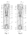
D'autres objets et avantages de l'invention apparaîtront dans la description qui suit, faite en référence aux
Dans la description, les termes de positionnement dans l'espace sont pris en référence à la position du flacon représenté sur les figures.In the description, the spatial positioning terms are taken with reference to the position of the bottle shown in the figures.
En relation avec les figures, on décrit ci-dessous un flacon destiné à contenir un produit fluide en vue de sa distribution. Dans des exemples particuliers, le produit peut être liquide, notamment un produit cosmétique de soin, de maquillage ou de parfumage, ou un produit pharmaceutique.In connection with the figures, there is described below a bottle for containing a fluid for distribution. In particular examples, the product may be liquid, in particular a cosmetic care, make-up or perfume product, or a pharmaceutical product.
Le flacon comprend un corps 1 dans lequel un réservoir 2 de conditionnement du produit est formé. Selon une application particulière, le réservoir 2 peut avoir une contenance comprise entre 1 et 10 ml de sorte à permettre la distribution d'échantillons de produit.The bottle comprises a
Dans les modes de réalisation représentés, le corps 1 est rigide, notamment en présentant une rigidité suffisante pour que le volume du réservoir 2 demeure sensiblement constant. Le corps 1 peut être monobloc, par exemple réalisé par injection-soufflage ou extrusion-soufflage, ou en plusieurs parties injectées puis assemblées, par exemple par soudure ultra-sons ou par friction rotative, en matière plastique rigide, en métal, par exemple en aluminium, ou en verre. En variante non représentée, le corps 1 peut être souple, notamment déformable lors de la distribution du produit.In the embodiments shown, the
Le flacon comprend un dispositif de prélèvement 3 du produit conditionné qui est monté de façon étanche sur le corps 1, notamment dans l'ouverture supérieure dudit corps. Le dispositif de prélèvement 3 est équipé d'un bouton poussoir 4 qui est pourvu d'un orifice de distribution 5 dudit produit, ledit bouton poussoir étant déplaçable réversiblement sur une course d'actionnement dudit dispositif entre une position au repos et une position enfoncée dans laquelle l'orifice de distribution 5 est en communication avec le réservoir 2 par l'intermédiaire dudit dispositif.The bottle comprises a
Dans les modes de réalisation représentés, le dispositif de prélèvement comprend une pompe 3 de distribution actionnée manuellement au moyen d'un bouton poussoir 4 qui est alimenté avec le produit sous pression en vue de sa distribution.In the embodiments shown, the sampling device comprises a dispensing
La pompe 3 comprend des moyens d'alimentation en produit conditionné qui, sur les figures, comprennent un tube plongeur 6 disposé dans le réservoir 2, ledit tube étant équipé d'un clapet 7 d'entrée du produit dans la pompe 3. Le bouton poussoir 4 est monté sur le gicleur 8 de la pompe 3 en mettant l'orifice de distribution 5 en communication avec un canal de sortie 8a dudit gicleur.The
La pompe 3 comprend également un piston 9 monté autour du gicleur 8 pour délimiter une chambre de dosage 10, ledit gicleur étant déplaçable réversiblement sur une course de distribution - respectivement d'aspiration - dans laquelle le piston 9 ouvre - respectivement ferme - la communication entre le canal de sortie 8a et la chambre de dosage 10.The
Le bouton poussoir 4 comprend une zone supérieure permettant à l'utilisateur d'exercer un appui digital sur ledit bouton poussoir afin de pouvoir déplacer le gicleur 8 sur sa course de distribution jusqu'à une position enfoncée dudit bouton poussoir, le retour du bouton poussoir 4 en position de repos sur la course d'aspiration du gicleur 8 étant classiquement réalisé par un ressort 11.The
Le bouton poussoir 4 est équipé d'une buse de pulvérisation 12 qui est agencée pour distribuer radialement un aérosol du produit au travers de l'orifice de distribution 5. Toutefois, l'invention n'est pas limitée à un mode particulier de distribution du produit. En particulier, notamment pour un embout nasal de pulvérisation, le bouton poussoir 4 peut permettre une distribution axiale du produit et un autre type de dispositif de prélèvement 3 peut être envisagé.The
Le corps 1 du flacon est équipé d'une soupape 13 de remplissage du réservoir 2 qui est agencée pour permettre la mise en communication d'une source de produit avec ledit réservoir. La source de produit peut comprendre un réservoir source sur lequel est disposé un tube de sortie, le remplissage en produit du réservoir 2 étant réalisé par montage dudit tube en appui étanche sur la soupape 13 qui est agencée pour s'ouvrir de façon réversible.The
En particulier, on peut utiliser en tant que source de produit un flacon nourrice de contenance supérieure, ledit flacon étant équipé d'une pompe dont le bouton poussoir est retiré pour permettre la disposition du gicleur en appui étanche sur la soupape 13. En effet, outre l'ouverture de la soupape 13, l'appui étanche provoque l'ouverture de la pompe afin de permettre le passage du produit de remplissage au travers d'elle.In particular, it is possible to use as a product source a nipple of higher capacity, said bottle being equipped with a pump whose push button is removed to allow the arrangement of the nozzle in sealing engagement with the
Selon une autre réalisation, le réservoir source est formé à l'intérieur d'une poche souple qui peut être remplie de produit sans air ni gaz pour la bonne conservation dudit produit. Le transfert du produit dans le réservoir 2 est alors possible dans toutes les positions et la poche souple ne peut pas être détournée de son rôle de source puisque sans gaz propulseur ni pression interne, ni bouton poussoir pour actionner une éventuelle pompe ou valve associée au tube de sortie.According to another embodiment, the source reservoir is formed inside a flexible bag which can be filled with product without air or gas for the proper preservation of said product. The transfer of the product into the
Dans les modes de réalisation représentés, la soupape 13 de remplissage est disposée sur l'extrémité inférieure du corps 1, de sorte notamment à remplir le réservoir 2 par le fond du flacon, ce qui correspond à un geste intuitif.In the embodiments shown, the
Pour ce faire, l'extrémité inférieure du corps 1 présente un orifice 14 de communication avec le réservoir 2 et la soupape 13 présentent un gicleur 15 qui est mobile entre un état stable de fermeture étanche de l'orifice 14 et un état contraint d'ouverture dudit orifice pour la mise en communication étanche de la source de produit avec ledit réservoir.To do this, the lower end of the
En relation avec les figures, le gicleur 15 est pourvu d'un canal interne 16, ledit gicleur étant monté en translation dans une bague 17 qui est fixée de façon étanche dans une cage 18 formée sous le corps 1. La soupape 13 comprend en outre un ressort 19 de rappel du gicleur 15 en position de fermeture et deux joints respectivement externe 20 et interne 21 pour étanchéifier le montage du gicleur 15 dans la bague 17 et la mise en communication de la source de produit sur ledit gicleur.In connection with the figures, the
Le réservoir 2 présente une dépression d'air qui est agencée pour pouvoir réaliser le remplissage dudit réservoir en produit par mise en communication étanche de la source de produit avec ledit réservoir par l'intermédiaire de la soupape 13 de sorte que ladite dépression induise le remplissage dudit réservoir par aspiration du produit contenu dans ladite source. En particulier, la dépression d'air peut être de l'ordre de - 980 hPa.The
Selon une réalisation, la dépression d'air peut être réalisée par vidage du réservoir 2 au moyen d'un dispositif de prélèvement 3 du type sans reprise d'air (airless en anglais) dans le réservoir 2 en compensation du volume de produit distribué, l'aspiration du produit source étant alors utilisée pour recharger ledit réservoir.According to one embodiment, the air depression can be achieved by emptying the
Selon une autre réalisation, le réservoir 2 peut être vide de produit et présenter une dépression d'air initiale qui est utilisée pour réaliser le premier remplissage dudit réservoir en produit. Le dispositif de prélèvement 3 peut alors être du type sans reprise d'air pour permettre des remplissages ultérieurs ou avec reprise d'air pour limiter l'utilisation du flacon à un seul remplissage. Dans les modes de réalisation représentés, la pompe 3 présente un trou d'évent 22 qui est agencé pour permettre de compenser le volume de produit prélevé dans le réservoir 2 par de l'air.In another embodiment, the
Le flacon comprend en outre un capuchon 23 qui est associé au corps 1 en formant un espace interne 24 étanche dans lequel le bouton poussoir 4 est disposé, ledit espace interne présentant une dépression d'air et étant agencé pour maintenir ledit bouton poussoir en positon enfoncée de sorte à être en communication avec le réservoir 2. Ainsi, un équilibre de pression est réalisé entre l'espace interne 24 du capuchon 23 et le réservoir 2.The bottle further comprises a
En particulier, l'espace interne 24 est en communication avec le réservoir 2 puisque, en position enfoncée du bouton poussoir 4, le canal de sortie 8a du gicleur 8 et donc l'orifice de distribution 5 débouchant dans ledit espace interne est en communication avec le réservoir 2 par l'intermédiaire de la chambre de dosage 10. En outre, l'espace interne 24 est en communication avec le réservoir 2 par l'intermédiaire du trou d'évent 22.In particular, the
Ainsi, l'étanchéité de la dépression d'air du réservoir 2 n'est pas réalisée au niveau du dispositif de prélèvement 3 qui est maintenu en position ouverte, mais par l'association du capuchon 23 sur le corps 1, ladite association pouvant être facilement agencée pour conserver dans le temps ladite dépression d'air, notamment sans nécessiter de modification du dispositif de prélèvement 3.Thus, the tightness of the air depression of the
L'association étanche entre le capuchon 23 et le corps 1 peut être réalisée sous l'effet de la dépression d'air de sorte à permettre de visualiser une perte accidentelle de cette dépression puisque la dissociation du capuchon 23 ne permet plus le maintien du bouton poussoir 4 en position enfoncée. Ainsi, le capuchon 23 peut servir de témoin de vide pour montrer à l'opératrice si le flacon pourra être rempli par aspiration. En outre, cette réalisation permet, lors du remplissage du réservoir 2, de dissocier le capuchon 23 du corps 1 de sorte à permettre le retour du bouton poussoir 4 en position de repos.The sealed association between the
Dans les modes de réalisation représentés, le capuchon 23 présente une paroi supérieure 25 qui est en appui sur le bouton poussoir 4 pour le maintenir en position enfoncée, ladite paroi étant entourée par une jupe 26 présentant une portée d'association étanche 27 sur une paroi 28 du corps 1.In the embodiments shown, the
En particulier, la portée d'association 27 peut être déformée sous l'effet de la dépression d'air afin d'assurer son serrage étanche sur la paroi 28, ledit serrage pouvant être très faible voire nul lorsque la pression de l'espace interne 24 se rapproche de celle régnant à l'extérieur du capuchon 23.In particular, the
La paroi 28 représentée s'étend autour d'une collerette annulaire supérieure du corps 1 dans laquelle le bouton poussoir 4 est monté, la portée d'association 27 étant formée à l'intérieur du bord libre de la jupe 26 qui est monté autour de ladite paroi pour être serrée radialement sur ladite paroi.The
Sur la
Sur la
En relation avec les
En relation avec la
En particulier, la zone comprimable 26a est formée d'un soufflet réalisé en matériau élastiquement déformable, la paroi supérieure 25 et/ou la portée d'association 27 pouvant être également réalisée en matériau élastiquement déformable pour empêcher une utilisation du capuchon 23 lorsque le réservoir 2 contient du produit.In particular, the compressible zone 26a is formed of a bellows made of an elastically deformable material, the
Claims (13)
- Bottle for dispensing a fluid product comprising a body (1) wherein a reservoir (2) intended for the conditioning of said product is formed, said bottle further comprising a device for sampling (3) of said conditioned product which is mounted in a sealed manner on said body, said device for sampling being provided with a push-button (4) which is provided with a dispensing orifice (5) of said product, said push-button able to be displaced reversibly on an actuating stroke of said device between a position at rest and a depressed position wherein the dispensing orifice (5) is in communication with the reservoir (2) by the intermediary of said device, said body being equipped with a filling valve (13) of said reservoir which is arranged in order to allow for the putting into communication of a product source with said reservoir, the reservoir (2) having an air depression which is arranged in order to be able to carry out the filling of the reservoir (2) with product by putting into sealed communication of a product source with said reservoir by the intermediary of the valve (13) in such a way that said depression induces the filling of said reservoir through suction of the product contained in said source, said bottle further comprising a cap (23), characterized in that the cap (23) is associated to the body (1) by forming a sealed internal space (24) wherein said push-button is arranged, said internal space having an air depression and being arranged to maintain said push-button in depressed position in such a way as to be in communication with the reservoir (2).
- Bottle for dispensing according to claim 1, characterised in that the cap (23) has an upper wall (25) which is pressing against the push-button (4) in order to maintain it in depressed position.
- Bottle for dispensing according to claim 2, characterised in that the upper wall (25) is surrounded by a skirt (26) having a sealed association surface (27) on a wall (28) of the body (1).
- Bottle for dispensing according to any of claims 1 to 3, characterised in that the sealed association between the cap (23) and the body (1) is carried out under the effect of the air depression.
- Bottle for dispensing according to claim 3 and 4 when claim 4 depends of claim 3, characterised in that the association surface (27) is deformed under the effect of the air depression in order to provide for its tight seal on the wall (28).
- Bottle for dispensing according to any of claims 3 to 5, characterised in that the association surface (27) is mounted around the wall (28) in order to be radially tightened on said wall.
- Bottle for dispensing according to any of claims 3 to 6, characterised in that the body (1) has a groove (29) wherein the association surface (27) is arranged in order to be thrust against the corner on the wall (28).
- Bottle for dispensing according to any of claims 3 to 7, characterised in that a seal (30) is inserted between the association surface (27) and the wall (28) of the body (1).
- Bottle for dispensing according to any of claims 3 to 8, characterised in that the skirt (26) is rigid and has an axial dimension that is arranged to maintain the push-button (4) in depressed position.
- Bottle for dispensing according to claim 9, characterised in that the association surface (27) has an axial dimension which is less than the actuating stroke of the push-button (4).
- Bottle for dispensing according to any of claims 3 to 8, characterised in that the skirt (26) has an elastically compressible zone (26a) which is arranged between the upper wall (25) and the association surface (27), said zone being compressed by the air depression in order to provide for the maintaining of the push-button (4) in depressed position.
- Bottle for dispensing according to any of claims 1 to 11, characterised in that the device for sampling (3) is of the airless type in the reservoir (2) for conditioning as compensation for the volume of product distributed.
- Bottle for dispensing according to any of claims 1 to 11, characterised in that the device for sampling (3) has a vent hole (22) which is arranged in order to make it possible to compensate for the volume of product sampled in the reservoir (2) by air, said vent hole being in communication with the sealed internal space (24).
Applications Claiming Priority (1)
| Application Number | Priority Date | Filing Date | Title |
|---|---|---|---|
| FR1155008A FR2976270B1 (en) | 2011-06-08 | 2011-06-08 | FLUID FOR DISPENSING A FLUID PRODUCT |
Publications (2)
| Publication Number | Publication Date |
|---|---|
| EP2532443A1 EP2532443A1 (en) | 2012-12-12 |
| EP2532443B1 true EP2532443B1 (en) | 2015-02-25 |
Family
ID=46052682
Family Applications (1)
| Application Number | Title | Priority Date | Filing Date |
|---|---|---|---|
| EP12168751.1A Not-in-force EP2532443B1 (en) | 2011-06-08 | 2012-05-21 | Vial for dispensing a fluid product |
Country Status (4)
| Country | Link |
|---|---|
| US (1) | US8783523B2 (en) |
| EP (1) | EP2532443B1 (en) |
| ES (1) | ES2535801T3 (en) |
| FR (1) | FR2976270B1 (en) |
Families Citing this family (15)
| Publication number | Priority date | Publication date | Assignee | Title |
|---|---|---|---|---|
| FR2966129B1 (en) * | 2010-10-18 | 2012-10-19 | Rexam Dispensing Sys | METHOD AND FLUID FOR DISPENSING A FLUID PRODUCT |
| FR2971774B1 (en) * | 2011-02-23 | 2014-06-06 | Valois Sas | FLUID PRODUCT DISPENSER |
| CN202321216U (en) * | 2011-12-14 | 2012-07-11 | 东莞怡信磁碟有限公司 | Refillable spraying bottle |
| FR2994867B1 (en) * | 2012-09-04 | 2014-09-26 | Rexam Dispensing Sys | FLUID FOR DISPENSING A FLUID PRODUCT |
| FR2995290B1 (en) * | 2012-09-13 | 2014-09-26 | Rexam Dispensing Sys | FILLABLE VIAL FOR DISPENSING A FLUID PRODUCT |
| FR2996828B1 (en) * | 2012-10-15 | 2014-10-24 | Rexam Dispensing Sys | FILLABLE VIAL FOR DISPENSING A FLUID PRODUCT |
| FR2996829B1 (en) * | 2012-10-15 | 2014-10-24 | Rexam Dispensing Sys | FILLABLE VIAL FOR DISPENSING A FLUID PRODUCT |
| FR2999958B1 (en) * | 2012-12-20 | 2015-08-14 | Aptar France Sas | HEAD OF DISTRIBUTION OF FLUID PRODUCT. |
| FR3003479B1 (en) * | 2013-03-22 | 2015-04-10 | Aptar France Sas | RECHARGEABLE FLUID PRODUCT DISPENSER. |
| FR3004429B1 (en) * | 2013-04-16 | 2015-11-27 | Rexam Dispensing Sys | ASSEMBLY COMPRISING A FILLABLE VIAL AND A PRODUCT SOURCE |
| FR3004624B1 (en) * | 2013-04-22 | 2015-05-15 | Aptar France Sas | FLUID PRODUCT DISPENSER. |
| EP3010833A4 (en) * | 2013-06-19 | 2017-03-22 | Beauty Union Global Limited | Refillable spray bottle |
| US20150108147A1 (en) * | 2013-10-17 | 2015-04-23 | Ming King Wong | Refill system |
| CN109717598B (en) * | 2018-11-26 | 2021-09-21 | 佛山市上富塑料制品有限公司 | Cosmetic bottle with pressure |
| US11679403B1 (en) | 2022-02-02 | 2023-06-20 | Ries Ries Inc | Travel dispenser for dispensing a fluid |
Family Cites Families (18)
| Publication number | Priority date | Publication date | Assignee | Title |
|---|---|---|---|---|
| US2443981A (en) * | 1945-03-19 | 1948-06-22 | Frank F Funk | Grease gun charger |
| US2870943A (en) * | 1957-03-04 | 1959-01-27 | Cook Chemical Company | Pump-type liquid sprayer having hold-down cap |
| NL106608C (en) * | 1958-09-09 | |||
| US3050219A (en) * | 1959-05-29 | 1962-08-21 | Valve Corp Of America Inc | Locking cap dispensers |
| US4981233A (en) * | 1989-08-14 | 1991-01-01 | Scheurer Robert S | Positive pressure closure lid for beverage can |
| IT237024Y1 (en) * | 1995-07-11 | 2000-08-31 | Coster Tecnologie Speciali Spa | LIQUID VAPORIZER WITH FILLING CAP |
| FR2739088B1 (en) * | 1995-09-26 | 1997-10-24 | Oreal | DISPENSER CONTAINER FOR A LIQUID PRODUCT UNDER PRESSURE EQUIPPED WITH A GAS DISCHARGE DEVICE |
| US6112949A (en) * | 1998-09-28 | 2000-09-05 | Robert V. Rhodes | Dual cap dispenser |
| FR2835513B1 (en) * | 2002-02-06 | 2004-08-06 | Rexam Sofab | DEVICE FOR PERFUME SAMPLES |
| FR2854131B1 (en) * | 2003-04-28 | 2005-07-08 | Valois Sas | FLUID PRODUCT TANK FILLING METHOD, FLUID PRODUCT FILLING ASSEMBLY AND FILLING SOURCE |
| US6997219B2 (en) * | 2003-05-12 | 2006-02-14 | Medical Instill Technologies, Inc. | Dispenser and apparatus and method for filling a dispenser |
| FR2854821B1 (en) * | 2003-05-16 | 2006-12-08 | Oreal | ASSEMBLY FOR PACKAGING AND DISPENSING A PRODUCT, IN PARTICULAR IN THE FORM OF A SAMPLE |
| FR2868050B1 (en) * | 2004-03-24 | 2006-06-02 | Oreal | PRODUCT PACKAGING AND DISPENSING ASSEMBLY |
| IL161515A (en) * | 2004-04-20 | 2012-10-31 | Beauty Union Global Ltd | Refill perfume bottle |
| ITMO20050057A1 (en) * | 2005-03-15 | 2006-09-16 | Lameplast Spa | PACKAGE FOR PRODUCTS WITH ESTEMPORANEA PREPARATION, PARTICULARLY MEDICINAL, PHARMACEUTICAL, COSMETIC OR SIMILAR. |
| EP2080710A1 (en) * | 2008-01-15 | 2009-07-22 | InBev S.A. | Assembly of a container and a closure |
| CN201329329Y (en) * | 2008-12-26 | 2009-10-21 | 东莞怡信磁碟有限公司 | Improved portable rechargeable liquid spraying bottle |
| US8616414B2 (en) * | 2009-02-09 | 2013-12-31 | Gojo Industries, Inc. | Bellows foam dispenser |
-
2011
- 2011-06-08 FR FR1155008A patent/FR2976270B1/en not_active Expired - Fee Related
-
2012
- 2012-05-21 ES ES12168751.1T patent/ES2535801T3/en active Active
- 2012-05-21 EP EP12168751.1A patent/EP2532443B1/en not_active Not-in-force
- 2012-06-01 US US13/486,496 patent/US8783523B2/en not_active Expired - Fee Related
Also Published As
| Publication number | Publication date |
|---|---|
| US20120312842A1 (en) | 2012-12-13 |
| FR2976270A1 (en) | 2012-12-14 |
| ES2535801T3 (en) | 2015-05-18 |
| EP2532443A1 (en) | 2012-12-12 |
| US8783523B2 (en) | 2014-07-22 |
| FR2976270B1 (en) | 2013-06-28 |
Similar Documents
| Publication | Publication Date | Title |
|---|---|---|
| EP2532443B1 (en) | Vial for dispensing a fluid product | |
| EP2703091B1 (en) | Dispensing bottle for a fluid product | |
| EP2532442B1 (en) | Vial for dispensing a fluid product | |
| EP2441344B1 (en) | Method and bottle for dispensing a fluid product | |
| EP2511196B1 (en) | Dispensing unit for a fluid provided with a filling valve | |
| EP2719466B1 (en) | Refillable bottle of a fluid dispenser | |
| EP2719467B1 (en) | Refillable bottle of a fluid dispenser | |
| EP2708286B1 (en) | Fillable vial for dispensing a fluid product | |
| EP2792418B1 (en) | Assembly including a refillable bottle and a product source | |
| FR3030312B1 (en) | SYSTEM FOR DISPENSING A FLUID PRODUCT | |
| EP2397422B1 (en) | Fluid dispensing system | |
| EP2335833A1 (en) | Bottle for distributing a fluid product including a filling valve | |
| EP3002064B1 (en) | Refillable vial for dispensing a fluid product | |
| EP3002063B1 (en) | Refillable vial for dispensing a fluid product | |
| FR2894633A1 (en) | SLIDING SHOULDER PUMP | |
| EP2703090B1 (en) | Vial for dispensing a fluid product | |
| EP2532441B1 (en) | Assembly comprising a vial for dispensing a fluid product arranged in a bag | |
| FR2984768A1 (en) | Distribution system for use in distribution bottle for distributing e.g. lotion of cosmetic product, has downstream closing unit opened by applying pressure on product, which is delivered in distribution pipe through exhaust valve |
Legal Events
| Date | Code | Title | Description |
|---|---|---|---|
| PUAI | Public reference made under article 153(3) epc to a published international application that has entered the european phase |
Free format text: ORIGINAL CODE: 0009012 |
|
| AK | Designated contracting states |
Kind code of ref document: A1 Designated state(s): AL AT BE BG CH CY CZ DE DK EE ES FI FR GB GR HR HU IE IS IT LI LT LU LV MC MK MT NL NO PL PT RO RS SE SI SK SM TR |
|
| AX | Request for extension of the european patent |
Extension state: BA ME |
|
| 17P | Request for examination filed |
Effective date: 20130517 |
|
| RAP1 | Party data changed (applicant data changed or rights of an application transferred) |
Owner name: ALBEA LE TREPORT |
|
| GRAP | Despatch of communication of intention to grant a patent |
Free format text: ORIGINAL CODE: EPIDOSNIGR1 |
|
| INTG | Intention to grant announced |
Effective date: 20140923 |
|
| GRAS | Grant fee paid |
Free format text: ORIGINAL CODE: EPIDOSNIGR3 |
|
| GRAA | (expected) grant |
Free format text: ORIGINAL CODE: 0009210 |
|
| AK | Designated contracting states |
Kind code of ref document: B1 Designated state(s): AL AT BE BG CH CY CZ DE DK EE ES FI FR GB GR HR HU IE IS IT LI LT LU LV MC MK MT NL NO PL PT RO RS SE SI SK SM TR |
|
| REG | Reference to a national code |
Ref country code: GB Ref legal event code: FG4D Free format text: NOT ENGLISH |
|
| REG | Reference to a national code |
Ref country code: CH Ref legal event code: EP |
|
| REG | Reference to a national code |
Ref country code: IE Ref legal event code: FG4D Free format text: LANGUAGE OF EP DOCUMENT: FRENCH |
|
| REG | Reference to a national code |
Ref country code: DE Ref legal event code: R096 Ref document number: 602012005371 Country of ref document: DE Effective date: 20150409 |
|
| REG | Reference to a national code |
Ref country code: AT Ref legal event code: REF Ref document number: 711468 Country of ref document: AT Kind code of ref document: T Effective date: 20150415 |
|
| REG | Reference to a national code |
Ref country code: ES Ref legal event code: FG2A Ref document number: 2535801 Country of ref document: ES Kind code of ref document: T3 Effective date: 20150518 |
|
| REG | Reference to a national code |
Ref country code: FR Ref legal event code: PLFP Year of fee payment: 4 |
|
| REG | Reference to a national code |
Ref country code: NL Ref legal event code: VDEP Effective date: 20150225 |
|
| REG | Reference to a national code |
Ref country code: AT Ref legal event code: MK05 Ref document number: 711468 Country of ref document: AT Kind code of ref document: T Effective date: 20150225 |
|
| REG | Reference to a national code |
Ref country code: LT Ref legal event code: MG4D |
|
| PG25 | Lapsed in a contracting state [announced via postgrant information from national office to epo] |
Ref country code: LT Free format text: LAPSE BECAUSE OF FAILURE TO SUBMIT A TRANSLATION OF THE DESCRIPTION OR TO PAY THE FEE WITHIN THE PRESCRIBED TIME-LIMIT Effective date: 20150225 Ref country code: NO Free format text: LAPSE BECAUSE OF FAILURE TO SUBMIT A TRANSLATION OF THE DESCRIPTION OR TO PAY THE FEE WITHIN THE PRESCRIBED TIME-LIMIT Effective date: 20150525 Ref country code: FI Free format text: LAPSE BECAUSE OF FAILURE TO SUBMIT A TRANSLATION OF THE DESCRIPTION OR TO PAY THE FEE WITHIN THE PRESCRIBED TIME-LIMIT Effective date: 20150225 Ref country code: SE Free format text: LAPSE BECAUSE OF FAILURE TO SUBMIT A TRANSLATION OF THE DESCRIPTION OR TO PAY THE FEE WITHIN THE PRESCRIBED TIME-LIMIT Effective date: 20150225 Ref country code: HR Free format text: LAPSE BECAUSE OF FAILURE TO SUBMIT A TRANSLATION OF THE DESCRIPTION OR TO PAY THE FEE WITHIN THE PRESCRIBED TIME-LIMIT Effective date: 20150225 |
|
| PG25 | Lapsed in a contracting state [announced via postgrant information from national office to epo] |
Ref country code: AT Free format text: LAPSE BECAUSE OF FAILURE TO SUBMIT A TRANSLATION OF THE DESCRIPTION OR TO PAY THE FEE WITHIN THE PRESCRIBED TIME-LIMIT Effective date: 20150225 Ref country code: IS Free format text: LAPSE BECAUSE OF FAILURE TO SUBMIT A TRANSLATION OF THE DESCRIPTION OR TO PAY THE FEE WITHIN THE PRESCRIBED TIME-LIMIT Effective date: 20150625 Ref country code: RS Free format text: LAPSE BECAUSE OF FAILURE TO SUBMIT A TRANSLATION OF THE DESCRIPTION OR TO PAY THE FEE WITHIN THE PRESCRIBED TIME-LIMIT Effective date: 20150225 Ref country code: GR Free format text: LAPSE BECAUSE OF FAILURE TO SUBMIT A TRANSLATION OF THE DESCRIPTION OR TO PAY THE FEE WITHIN THE PRESCRIBED TIME-LIMIT Effective date: 20150526 Ref country code: LV Free format text: LAPSE BECAUSE OF FAILURE TO SUBMIT A TRANSLATION OF THE DESCRIPTION OR TO PAY THE FEE WITHIN THE PRESCRIBED TIME-LIMIT Effective date: 20150225 |
|
| PG25 | Lapsed in a contracting state [announced via postgrant information from national office to epo] |
Ref country code: NL Free format text: LAPSE BECAUSE OF FAILURE TO SUBMIT A TRANSLATION OF THE DESCRIPTION OR TO PAY THE FEE WITHIN THE PRESCRIBED TIME-LIMIT Effective date: 20150225 |
|
| PG25 | Lapsed in a contracting state [announced via postgrant information from national office to epo] |
Ref country code: RO Free format text: LAPSE BECAUSE OF FAILURE TO SUBMIT A TRANSLATION OF THE DESCRIPTION OR TO PAY THE FEE WITHIN THE PRESCRIBED TIME-LIMIT Effective date: 20150225 Ref country code: CZ Free format text: LAPSE BECAUSE OF FAILURE TO SUBMIT A TRANSLATION OF THE DESCRIPTION OR TO PAY THE FEE WITHIN THE PRESCRIBED TIME-LIMIT Effective date: 20150225 Ref country code: DK Free format text: LAPSE BECAUSE OF FAILURE TO SUBMIT A TRANSLATION OF THE DESCRIPTION OR TO PAY THE FEE WITHIN THE PRESCRIBED TIME-LIMIT Effective date: 20150225 Ref country code: EE Free format text: LAPSE BECAUSE OF FAILURE TO SUBMIT A TRANSLATION OF THE DESCRIPTION OR TO PAY THE FEE WITHIN THE PRESCRIBED TIME-LIMIT Effective date: 20150225 Ref country code: SK Free format text: LAPSE BECAUSE OF FAILURE TO SUBMIT A TRANSLATION OF THE DESCRIPTION OR TO PAY THE FEE WITHIN THE PRESCRIBED TIME-LIMIT Effective date: 20150225 |
|
| REG | Reference to a national code |
Ref country code: DE Ref legal event code: R097 Ref document number: 602012005371 Country of ref document: DE |
|
| PG25 | Lapsed in a contracting state [announced via postgrant information from national office to epo] |
Ref country code: PL Free format text: LAPSE BECAUSE OF FAILURE TO SUBMIT A TRANSLATION OF THE DESCRIPTION OR TO PAY THE FEE WITHIN THE PRESCRIBED TIME-LIMIT Effective date: 20150225 |
|
| PG25 | Lapsed in a contracting state [announced via postgrant information from national office to epo] |
Ref country code: IT Free format text: LAPSE BECAUSE OF FAILURE TO SUBMIT A TRANSLATION OF THE DESCRIPTION OR TO PAY THE FEE WITHIN THE PRESCRIBED TIME-LIMIT Effective date: 20150225 |
|
| REG | Reference to a national code |
Ref country code: CH Ref legal event code: PL |
|
| PLBE | No opposition filed within time limit |
Free format text: ORIGINAL CODE: 0009261 |
|
| STAA | Information on the status of an ep patent application or granted ep patent |
Free format text: STATUS: NO OPPOSITION FILED WITHIN TIME LIMIT |
|
| PG25 | Lapsed in a contracting state [announced via postgrant information from national office to epo] |
Ref country code: LI Free format text: LAPSE BECAUSE OF NON-PAYMENT OF DUE FEES Effective date: 20150531 Ref country code: MC Free format text: LAPSE BECAUSE OF FAILURE TO SUBMIT A TRANSLATION OF THE DESCRIPTION OR TO PAY THE FEE WITHIN THE PRESCRIBED TIME-LIMIT Effective date: 20150225 Ref country code: LU Free format text: LAPSE BECAUSE OF FAILURE TO SUBMIT A TRANSLATION OF THE DESCRIPTION OR TO PAY THE FEE WITHIN THE PRESCRIBED TIME-LIMIT Effective date: 20150521 Ref country code: CH Free format text: LAPSE BECAUSE OF NON-PAYMENT OF DUE FEES Effective date: 20150531 |
|
| 26N | No opposition filed |
Effective date: 20151126 |
|
| REG | Reference to a national code |
Ref country code: IE Ref legal event code: MM4A |
|
| PG25 | Lapsed in a contracting state [announced via postgrant information from national office to epo] |
Ref country code: SI Free format text: LAPSE BECAUSE OF FAILURE TO SUBMIT A TRANSLATION OF THE DESCRIPTION OR TO PAY THE FEE WITHIN THE PRESCRIBED TIME-LIMIT Effective date: 20150225 |
|
| PG25 | Lapsed in a contracting state [announced via postgrant information from national office to epo] |
Ref country code: IE Free format text: LAPSE BECAUSE OF NON-PAYMENT OF DUE FEES Effective date: 20150521 |
|
| REG | Reference to a national code |
Ref country code: FR Ref legal event code: PLFP Year of fee payment: 5 |
|
| PG25 | Lapsed in a contracting state [announced via postgrant information from national office to epo] |
Ref country code: MT Free format text: LAPSE BECAUSE OF FAILURE TO SUBMIT A TRANSLATION OF THE DESCRIPTION OR TO PAY THE FEE WITHIN THE PRESCRIBED TIME-LIMIT Effective date: 20150225 |
|
| GBPC | Gb: european patent ceased through non-payment of renewal fee |
Effective date: 20160521 |
|
| REG | Reference to a national code |
Ref country code: FR Ref legal event code: PLFP Year of fee payment: 6 |
|
| PG25 | Lapsed in a contracting state [announced via postgrant information from national office to epo] |
Ref country code: SM Free format text: LAPSE BECAUSE OF FAILURE TO SUBMIT A TRANSLATION OF THE DESCRIPTION OR TO PAY THE FEE WITHIN THE PRESCRIBED TIME-LIMIT Effective date: 20150225 Ref country code: HU Free format text: LAPSE BECAUSE OF FAILURE TO SUBMIT A TRANSLATION OF THE DESCRIPTION OR TO PAY THE FEE WITHIN THE PRESCRIBED TIME-LIMIT; INVALID AB INITIO Effective date: 20120521 Ref country code: BG Free format text: LAPSE BECAUSE OF FAILURE TO SUBMIT A TRANSLATION OF THE DESCRIPTION OR TO PAY THE FEE WITHIN THE PRESCRIBED TIME-LIMIT Effective date: 20150225 Ref country code: GB Free format text: LAPSE BECAUSE OF NON-PAYMENT OF DUE FEES Effective date: 20160521 |
|
| PG25 | Lapsed in a contracting state [announced via postgrant information from national office to epo] |
Ref country code: CY Free format text: LAPSE BECAUSE OF FAILURE TO SUBMIT A TRANSLATION OF THE DESCRIPTION OR TO PAY THE FEE WITHIN THE PRESCRIBED TIME-LIMIT Effective date: 20150225 |
|
| PG25 | Lapsed in a contracting state [announced via postgrant information from national office to epo] |
Ref country code: BE Free format text: LAPSE BECAUSE OF NON-PAYMENT OF DUE FEES Effective date: 20150531 |
|
| PG25 | Lapsed in a contracting state [announced via postgrant information from national office to epo] |
Ref country code: TR Free format text: LAPSE BECAUSE OF FAILURE TO SUBMIT A TRANSLATION OF THE DESCRIPTION OR TO PAY THE FEE WITHIN THE PRESCRIBED TIME-LIMIT Effective date: 20150225 |
|
| REG | Reference to a national code |
Ref country code: FR Ref legal event code: PLFP Year of fee payment: 7 |
|
| PG25 | Lapsed in a contracting state [announced via postgrant information from national office to epo] |
Ref country code: PT Free format text: LAPSE BECAUSE OF FAILURE TO SUBMIT A TRANSLATION OF THE DESCRIPTION OR TO PAY THE FEE WITHIN THE PRESCRIBED TIME-LIMIT Effective date: 20150225 Ref country code: MK Free format text: LAPSE BECAUSE OF FAILURE TO SUBMIT A TRANSLATION OF THE DESCRIPTION OR TO PAY THE FEE WITHIN THE PRESCRIBED TIME-LIMIT Effective date: 20150225 |
|
| PGFP | Annual fee paid to national office [announced via postgrant information from national office to epo] |
Ref country code: ES Payment date: 20180601 Year of fee payment: 7 Ref country code: DE Payment date: 20180529 Year of fee payment: 7 |
|
| PGFP | Annual fee paid to national office [announced via postgrant information from national office to epo] |
Ref country code: FR Payment date: 20180525 Year of fee payment: 7 |
|
| PG25 | Lapsed in a contracting state [announced via postgrant information from national office to epo] |
Ref country code: AL Free format text: LAPSE BECAUSE OF FAILURE TO SUBMIT A TRANSLATION OF THE DESCRIPTION OR TO PAY THE FEE WITHIN THE PRESCRIBED TIME-LIMIT Effective date: 20150225 |
|
| REG | Reference to a national code |
Ref country code: DE Ref legal event code: R119 Ref document number: 602012005371 Country of ref document: DE |
|
| PG25 | Lapsed in a contracting state [announced via postgrant information from national office to epo] |
Ref country code: DE Free format text: LAPSE BECAUSE OF NON-PAYMENT OF DUE FEES Effective date: 20191203 |
|
| PG25 | Lapsed in a contracting state [announced via postgrant information from national office to epo] |
Ref country code: FR Free format text: LAPSE BECAUSE OF NON-PAYMENT OF DUE FEES Effective date: 20190531 |
|
| REG | Reference to a national code |
Ref country code: ES Ref legal event code: FD2A Effective date: 20200928 |
|
| PG25 | Lapsed in a contracting state [announced via postgrant information from national office to epo] |
Ref country code: ES Free format text: LAPSE BECAUSE OF NON-PAYMENT OF DUE FEES Effective date: 20190522 |