EP2531735B1 - Hydraulic section for load sensing applications and multiple hydraulic distributor - Google Patents
Hydraulic section for load sensing applications and multiple hydraulic distributor Download PDFInfo
- Publication number
- EP2531735B1 EP2531735B1 EP10707685.3A EP10707685A EP2531735B1 EP 2531735 B1 EP2531735 B1 EP 2531735B1 EP 10707685 A EP10707685 A EP 10707685A EP 2531735 B1 EP2531735 B1 EP 2531735B1
- Authority
- EP
- European Patent Office
- Prior art keywords
- pressure
- hydraulic
- chamber
- section
- piston
- Prior art date
- Legal status (The legal status is an assumption and is not a legal conclusion. Google has not performed a legal analysis and makes no representation as to the accuracy of the status listed.)
- Active
Links
Images


Classifications
-
- F—MECHANICAL ENGINEERING; LIGHTING; HEATING; WEAPONS; BLASTING
- F15—FLUID-PRESSURE ACTUATORS; HYDRAULICS OR PNEUMATICS IN GENERAL
- F15B—SYSTEMS ACTING BY MEANS OF FLUIDS IN GENERAL; FLUID-PRESSURE ACTUATORS, e.g. SERVOMOTORS; DETAILS OF FLUID-PRESSURE SYSTEMS, NOT OTHERWISE PROVIDED FOR
- F15B13/00—Details of servomotor systems ; Valves for servomotor systems
- F15B13/02—Fluid distribution or supply devices characterised by their adaptation to the control of servomotors
- F15B13/04—Fluid distribution or supply devices characterised by their adaptation to the control of servomotors for use with a single servomotor
- F15B13/0416—Fluid distribution or supply devices characterised by their adaptation to the control of servomotors for use with a single servomotor with means or adapted for load sensing
- F15B13/0417—Load sensing elements; Internal fluid connections therefor; Anti-saturation or pressure-compensation valves
-
- F—MECHANICAL ENGINEERING; LIGHTING; HEATING; WEAPONS; BLASTING
- F15—FLUID-PRESSURE ACTUATORS; HYDRAULICS OR PNEUMATICS IN GENERAL
- F15B—SYSTEMS ACTING BY MEANS OF FLUIDS IN GENERAL; FLUID-PRESSURE ACTUATORS, e.g. SERVOMOTORS; DETAILS OF FLUID-PRESSURE SYSTEMS, NOT OTHERWISE PROVIDED FOR
- F15B11/00—Servomotor systems without provision for follow-up action; Circuits therefor
- F15B11/16—Servomotor systems without provision for follow-up action; Circuits therefor with two or more servomotors
- F15B11/161—Servomotor systems without provision for follow-up action; Circuits therefor with two or more servomotors with sensing of servomotor demand or load
- F15B11/162—Servomotor systems without provision for follow-up action; Circuits therefor with two or more servomotors with sensing of servomotor demand or load for giving priority to particular servomotors or users
Definitions
- the present invention has as its subject a hydraulic section for load sensing applications, and a multiple hydraulic distributor using one or more such hydraulic sections.
- a load sensing hydraulic system allows the pressure drop to be maintained substantially constant through a metering orifice of the spool valve of a hydraulic section.
- a load sensing hydraulic system has application in operating machines which require the simultaneous performance of a plurality of movements.
- an operating machine with a rotating turret such as, for example, an excavator or a telescopic loader, in which the rotation of the cabin, the extension of the arm and the movement of the bucket are managed independently of each other.
- 'priority section we mean a section which, in conditions of saturation of the flow, does not participate in the proportional reduction of the flow delivered but maintains a constant flow, forcing the other sections to further reduce their flow.
- each flow-sharing section is provided with at least one pressure compensation element and is able to actuate a proportional reduction of flow in case of undersupply (or saturation).
- undersupply or saturation
- the movement of the machine actuated by means of the priority section does not undergo variations in speed in case of saturation, as happens however with movements whose control is entrusted to the flow-sharing sections.
- Another similar solution is the one described in the document WO2009/001377 .
- hybrid distributors tend to be very bulky because the flow-sharing sections and the priority sections are difficult to accommodate side by side because of the different configurations of the internal channels.
- the technical task at the root of the present invention is to propose a hydraulic section for load sensing applications and a multiple hydraulic distributor which will overcome the disadvantages of the known art cited above.
- Another object of the present invention is to make available a hydraulic section for load sensing applications which is structurally simpler, and therefore cheaper, than hydraulic sections in the known art.
- a further object of the present invention is to propose a hydraulic section for load sensing applications in which reverse flow from the workports to the feed line is eliminated, or reduced as far as possible.
- Another object of the present invention is to make available a multiple hydraulic distributor having a simplified and more compact structure by comparison with hydraulic distributors in the known art.
- no. 10 indicates a multiple hydraulic distributor comprising a plurality of hydraulic sections 1 for load sensing applications. At least one of the hydraulic sections 1 is a priority section, while the other hydraulic sections 1 are flow-sharing sections.
- each hydraulic section 1 comprises a main spool 2 longitudinally displaceable within said section 1 in order to selectively transmit pressurised hydraulic fluid coming from a feed line Pal from a pump 100 to workports A,B through a metering orifice 3.
- the main spool 2 is of the six-way three-position type. It is anyway possible to create other configurations, for example four-position, where the additional position, called floating, connects both workports A, B to discharge.
- the main spool 2 is fed by a channel which coincides with the feed line Pal from the pump 100.
- a first chamber 7 is interposed between the main spool 2 and a first end 16a of compensation means 16.
- a second chamber 6 is situated at a second end 16b, opposite the first end 16a, of said compensation means 16.
- the said second chamber 6 is connectable to the feed line Pal by means of a predefined channel Pp in such a way that the hydraulic section 1 operates as a priority section ( figures 1 and 2 ), and else it is connectable to a line LS for detecting the highest load pressure so that said hydraulic section 1 operates as a flow-sharing section ( figures 3 and 4 ).
- the compensation means 16 comprise a pressure compensator 40 housed in a bore 9 formed within the hydraulic section 1.
- a plug 110 is provided which, interfacing with the walls of the bore 9 into which it is inserted, forms the second chamber 6.
- figure 3 illustrates a first embodiment (called "without check function") of the flow-sharing hydraulic section 1.
- a spring 80 is preferably housed in the second chamber 6 to elastically couple the compensator 40 and the plug 110.
- the predefined channel Pp though crossing the flow-sharing hydraulic section 1, remains unused because it is isolated by a portion of the plug 110. In this way, communication is excluded between this predefined channel Pp and the second chamber 6.
- Figure 4 illustrates a second embodiment (called “with check function") of the flow-sharing hydraulic section 1.
- an intermediate element 200 is interposed which faces said plug 110.
- the pressure compensator 40 and the intermediate element 200 are facing each other in such a way as to form an intermediate chamber 120 in which a spring 150 is housed.
- the compensation means 16 comprise a pressure compensator 4 and a piston 5 disposed in such a way as to be adjacent in an internal proximity zone 17.
- the pressure compensator 4 extends from the internal proximity zone 17 up to the first end 16a.
- the piston 5, extends from the internal proximity zone 17 up to the second end 16b.
- the pressure compensator 4 and the piston 5 are housed in a common bore 9 formed within hydraulic section 1.
- the piston 5 and the pressure compensator 4 are placed side by side so as to form, in the internal proximity zone 17, an intermediate chamber 12 suitable for communicating with the main spool 2 via a passage bridge 13.
- the predefined channel Pp and the line LS for detecting the highest load pressure are isolated from each other, irrespective of the position taken by the piston 5 within the common bore 9.
- the second chamber 6 houses a first spring 8 which is operatively active on the piston 5 in such a way as to move it away from said pressure compensator 4.
- the pressure compensator 4 and the piston 5 are pushed away from each other by a second spring 15, of negligible force, housed in the intermediate chamber 12.
- the presence of the second spring 15 ensures the assumption of a predetermined position by the pair "pressure compensator 4 - piston 5" in the absence of pressure.
- a plug 11 is provided which, interfacing with the piston 5, forms the second chamber 6. In this way, the plug 11 and the piston 5 are elastically coupled together by means of the first spring 8.
- a passage is provided which allows communication between the second chamber 6 and the predefined channel Pp. The piston 5 is therefore subject, over a surface which interfaces with the plug 11, to the pressure of the fluid from the predefined channel Pp.
- the piston 5 is provided with a valve 14 in order to establish selective communication between the line LS for detecting the highest load pressure and the intermediate chamber 12.
- the intermediate chamber 12 is, in its turn, subjected to the pressure of the passage bridge 13.
- the valve 14 is located within an annular interspace 19 formed between the piston 5 and the common bore 9.
- the valve 14 is of the ball type, maintained within the annular interspace 19 by means of an elastic element 21.
- the selective communication between the line LS for detecting the highest load pressure and the intermediate chamber 12 can be created solely by the seal exerted by the elastic element 21 against the annular interspace 19.
- the main spool 2 is displaceable between a neutral position, in which it does not communicate with the first chamber 7, and an operative position, in which it communicates with said first chamber 7, transmitting to it, through the metering orifice 3, the pressurised hydraulic fluid coming from the feed line Pal.
- the passage bridge 13 does not communicate with the workports A, B.
- the passage bridge 13 is put into communication with one of the workports A, B.
- the valve 14 closes off communication between this line LS for detecting the highest load pressure and the intermediate chamber 12 itself. If, however, the pressure in the line LS for detecting the highest load pressure is lower than the pressure in the intermediate chamber 12, the valve 14 opens communication between this line LS for detecting the highest load pressure and the intermediate chamber 12 itself. In practice, the pressure present at one of the workports A, B is transmitted, via the passage bridge 13 and the intermediate chamber 12, to the line LS for detecting the highest load pressure.
- the pressure compensator 4 is equipped, at its first end 16a, with regulating orifices 22. These regulating orifices 22 are preferably radial holes or notches. The displacements of the pressure compensator 4 within the bore 9 determine a proportional increase or decrease in the passage clearance generated by said regulating orifices 22 between the first chamber 7 and the bridge 13. It follows that, when the main spool 2 is in operative position, the flow delivered to the workports A, B will be substantially constant because it is dependent only on the load generated by the first spring 8.
- a drainage channel 18 is formed in the main spool 2, suitable for effecting selective communication between the passage bridge 13 (and therefore the intermediate chamber 12) and a discharge channel 23 of hydraulic section 1.
- the pressurised fluid coming from the predefined channel Pp pushes the piston 5 closer to the pressure compensator 4 in said internal proximity zone 17, overcoming the resistance of the first spring 8 and the second spring 15 (if present). This ensures a predetermined position for the pressure compensator 4 in the absence of a manoeuvre.
- the main spool 2 is in the operative position, said communication between the discharge channel 23 and the passage bridge 13, through the drainage channel 18, is interrupted.
- a hydraulic distributor 10 having a single priority section 1, while all the remaining sections 1 are of the flow-sharing type.
- the predefined channel Pp crosses all hydraulic sections 1, both the priority one and the flow-sharing ones. If the priority section 1 is the one with the greatest load, it will be precisely this one which transmits the regulating signal to a regulating organ 20 of the pump 100 (or alternatively to a three-way compensator of the inlet cover).
- the pressure in the line LS for detecting the highest load pressure (of the priority section 1) is transmitted to the regulating organ 20 of the pump 100 (or to the three-way compensator of the inlet cover) and to the second chamber 6 of all the flow-sharing hydraulic sections.
- the valve 14 in the priority section 1 closes off communication between the line LS for detecting the highest load pressure,and the intermediate chamber 12.
- the compensator 4 of the priority section 1 assumes a position such that the pressure drop between the second chamber 6 and the first chamber 7, and equivalently between the feed line Pal and the first chamber 7, is maintained substantially equal to that corresponding to the load on the first spring 8. It is therefore evident that in the priority section 1, the positions of the compensator 4 and of the piston 5 depend solely on the load on the first spring 8. As a consequence, when the main spool 2 is in the operative position, the flow delivered to the workports A, B is kept substantially constant.
- the proposed hydraulic section proves to be universal, i.e. usable both as a flow-sharing section and as a priority section.
- all the sections (both flow-sharing and priority) of the distributor are crossed by the predefined channel; however this channel is connected to the second chamber in the priority sections, while it is isolated in the flow-sharing sections.
- the design and construction of the proposed hydraulic section are simplified by comparison with the current state of the art because it is sufficient to prepare a single type of section and make different internal connections to pass from flow-sharing operation to priority operation.
- the compensation means are inserted into the appropriate bore, and then the bore itself is closed with the plug.
- the designed check function is integrated into the compensation function, avoiding the need to provide dedicated additional elements (e.g. check valves).
Landscapes
- Engineering & Computer Science (AREA)
- Physics & Mathematics (AREA)
- Fluid Mechanics (AREA)
- Mechanical Engineering (AREA)
- General Engineering & Computer Science (AREA)
- Fluid-Pressure Circuits (AREA)
Description
- The present invention has as its subject a hydraulic section for load sensing applications, and a multiple hydraulic distributor using one or more such hydraulic sections.
- A load sensing hydraulic system allows the pressure drop to be maintained substantially constant through a metering orifice of the spool valve of a hydraulic section. As is well-known, a load sensing hydraulic system has application in operating machines which require the simultaneous performance of a plurality of movements. Consider an operating machine with a rotating turret such as, for example, an excavator or a telescopic loader, in which the rotation of the cabin, the extension of the arm and the movement of the bucket are managed independently of each other.
- In a load sensing hydraulic system of traditional type, a request for more flow than the maximum deliverable by the pump is followed by the slowing or stoppage of the user with the highest load. This situation would prove particularly critical in the case quoted above, of the operating machine with a rotating turret, because the rotation of the cabin, rather than the extension of the arm, or rather than the movement of the bucket, could stop all of a sudden.
- To overcome this problem, distributors of flow-sharing type have been developed, where a request for more flow than the maximum deliverable by the pump is followed by a proportional reduction of the flow to all the users. Although all the users function simultaneously, irrespective of the flow delivered by the pump, there are some applications where the proportional reduction of the flow to some users could compromise the correct operability of the machine. With reference to the operating machine with rotating turret, the speed of rotation of the cabin could undergo numerous oscillations due to the repeated occurrence of conditions of undersupply (or saturation) and restoration of normal conditions of flow, posing considerable problems of control and safety for the operator in the cabin.
- It would thus be necessary to make the section corresponding to the critical user (i.e. rotation of the cabin) a priority section with respect to the other sections.
- By 'priority section' we mean a section which, in conditions of saturation of the flow, does not participate in the proportional reduction of the flow delivered but maintains a constant flow, forcing the other sections to further reduce their flow.
- An example of these hybrid solutions is shown in the document
GB2271870 WO2009/001377 . - The main disadvantage of hybrid solutions is connected with the constructional complexity of distributors, which use two types of section with different structures (flow-sharing and priority). In fact, as is clearly visible in document
W02009/001377 , the compensation means used in the two types of section are structurally different from each other. This obviously entails longer times and higher costs for design and production than those necessary for the design and production of a load sensing system of traditional type or a load sensing system of flow-sharing type. Add to this the production costs of different moulds for the flow-sharing and priority sections. - Furthermore, hybrid distributors tend to be very bulky because the flow-sharing sections and the priority sections are difficult to accommodate side by side because of the different configurations of the internal channels.
- Another problem which can occur in operating machines is that of reverse flow from the workports to the pump feed line which can cause undesired lowering of the load in the initial stage of lifting operations or undesired movements of the users. The expert in the field knows that to eliminate reverse flow, suitably configured non return valves are required, which further complicate the structure of the hydraulic section.
- In this context, the technical task at the root of the present invention is to propose a hydraulic section for load sensing applications and a multiple hydraulic distributor which will overcome the disadvantages of the known art cited above.
- In particular, it is an object of the present invention to make available a hydraulic section for load sensing applications which is universal, i.e. usable both as a flow-sharing and as a priority section.
- Another object of the present invention is to make available a hydraulic section for load sensing applications which is structurally simpler, and therefore cheaper, than hydraulic sections in the known art.
- A further object of the present invention is to propose a hydraulic section for load sensing applications in which reverse flow from the workports to the feed line is eliminated, or reduced as far as possible.
- Another object of the present invention is to make available a multiple hydraulic distributor having a simplified and more compact structure by comparison with hydraulic distributors in the known art.
- The declared technical task and the specified objects are substantially achieved by a hydraulic section for load sensing applications and a multiple hydraulic distributor, comprising the technical characteristics set forth in one or more of the attached claims.
- Further characteristics and advantages of the present invention will become clearer from the indicative, and therefore non-limiting, description of a preferred but not exclusive embodiment of a hydraulic section for load sensing applications and a multiple hydraulic distributor, as illustrated in the attached drawings, in which:
-
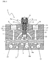
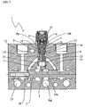
figures 1 and2 illustrate two different embodiments of a priority hydraulic section for load sensing applications, according to the present invention, in sectioned view; -
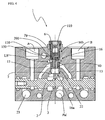
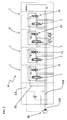
figures 3 and4 illustrate two different embodiments of a flow-sharing hydraulic section for load sensing applications, according to the present invention, in sectioned view; -
figure 5 illustrates the scheme of a multiple hydraulic distributor, according to the present invention: -
figure 6 illustrates an enlarged detail of the distributor offigure 5 , in schematic view. - With reference to
figure 5 , no. 10 indicates a multiple hydraulic distributor comprising a plurality ofhydraulic sections 1 for load sensing applications. At least one of thehydraulic sections 1 is a priority section, while the otherhydraulic sections 1 are flow-sharing sections. - With reference to
figures 1 to 4 , eachhydraulic section 1 comprises amain spool 2 longitudinally displaceable within saidsection 1 in order to selectively transmit pressurised hydraulic fluid coming from a feed line Pal from apump 100 to workports A,B through ametering orifice 3. In the embodiments here described and illustrated, themain spool 2 is of the six-way three-position type. It is anyway possible to create other configurations, for example four-position, where the additional position, called floating, connects both workports A, B to discharge. In particular, themain spool 2 is fed by a channel which coincides with the feed line Pal from thepump 100. - Downstream of the
main spool 2 pressure compensation means 16 are provided, able to maintain a substantially constant pressure-drop through themetering orifice 3. Afirst chamber 7 is interposed between themain spool 2 and afirst end 16a of compensation means 16. Asecond chamber 6 is situated at asecond end 16b, opposite thefirst end 16a, of said compensation means 16. Originally, the saidsecond chamber 6 is connectable to the feed line Pal by means of a predefined channel Pp in such a way that thehydraulic section 1 operates as a priority section (figures 1 and2 ), and else it is connectable to a line LS for detecting the highest load pressure so that saidhydraulic section 1 operates as a flow-sharing section (figures 3 and4 ). In both cases the predefined channel Pp and the line LS for detecting the highest load pressure are isolated from each other. With reference tofigures 3 and4 , a description in more detail is given below of the structure of a flow-sharinghydraulic section 1, especially as it relates to the compensation means 16. The compensation means 16 comprise apressure compensator 40 housed in abore 9 formed within thehydraulic section 1. To close this bore 9 aplug 110 is provided which, interfacing with the walls of thebore 9 into which it is inserted, forms thesecond chamber 6. In particular,figure 3 illustrates a first embodiment (called "without check function") of the flow-sharinghydraulic section 1. As may be seen, aspring 80 is preferably housed in thesecond chamber 6 to elastically couple thecompensator 40 and theplug 110. The predefined channel Pp, though crossing the flow-sharinghydraulic section 1, remains unused because it is isolated by a portion of theplug 110. In this way, communication is excluded between this predefined channel Pp and thesecond chamber 6. -
Figure 4 illustrates a second embodiment (called "with check function") of the flow-sharinghydraulic section 1. In it, between thepressure compensator 40 and theplug 110 anintermediate element 200 is interposed which faces saidplug 110. In particular, thepressure compensator 40 and theintermediate element 200 are facing each other in such a way as to form anintermediate chamber 120 in which aspring 150 is housed. - With reference to
figures 1 and2 , a description in more detail is given below of the structure of a priorityhydraulic section 1. Preferably, in the priorityhydraulic section 1, the compensation means 16 comprise apressure compensator 4 and apiston 5 disposed in such a way as to be adjacent in aninternal proximity zone 17. In particular, thepressure compensator 4 extends from theinternal proximity zone 17 up to thefirst end 16a. Thepiston 5, on the other hand, extends from theinternal proximity zone 17 up to thesecond end 16b. In particular, thepressure compensator 4 and thepiston 5 are housed in acommon bore 9 formed withinhydraulic section 1. Preferably, thepiston 5 and thepressure compensator 4 are placed side by side so as to form, in theinternal proximity zone 17, anintermediate chamber 12 suitable for communicating with themain spool 2 via apassage bridge 13. As specified above, the predefined channel Pp and the line LS for detecting the highest load pressure are isolated from each other, irrespective of the position taken by thepiston 5 within thecommon bore 9. - The
second chamber 6 houses afirst spring 8 which is operatively active on thepiston 5 in such a way as to move it away from saidpressure compensator 4. Preferably, in the embodiments here described and illustrated, thepressure compensator 4 and thepiston 5 are pushed away from each other by asecond spring 15, of negligible force, housed in theintermediate chamber 12. In particular, the presence of thesecond spring 15 ensures the assumption of a predetermined position by the pair "pressure compensator 4 -piston 5" in the absence of pressure. To close thecommon bore 9, aplug 11 is provided which, interfacing with thepiston 5, forms thesecond chamber 6. In this way, theplug 11 and thepiston 5 are elastically coupled together by means of thefirst spring 8. Between theplug 11 and thepiston 5 however a passage is provided which allows communication between thesecond chamber 6 and the predefined channel Pp. Thepiston 5 is therefore subject, over a surface which interfaces with theplug 11, to the pressure of the fluid from the predefined channel Pp. - Preferably, the
piston 5 is provided with avalve 14 in order to establish selective communication between the line LS for detecting the highest load pressure and theintermediate chamber 12. Theintermediate chamber 12 is, in its turn, subjected to the pressure of thepassage bridge 13. Thevalve 14 is located within anannular interspace 19 formed between thepiston 5 and thecommon bore 9. Preferably, thevalve 14 is of the ball type, maintained within theannular interspace 19 by means of anelastic element 21. - Alternatively, the selective communication between the line LS for detecting the highest load pressure and the
intermediate chamber 12 can be created solely by the seal exerted by theelastic element 21 against theannular interspace 19. - The operation of the priority hydraulic section for load sensing applications, according to the present invention, is described below.
- The
main spool 2 is displaceable between a neutral position, in which it does not communicate with thefirst chamber 7, and an operative position, in which it communicates with saidfirst chamber 7, transmitting to it, through themetering orifice 3, the pressurised hydraulic fluid coming from the feed line Pal. When themain spool 2 is in the neutral position, thepassage bridge 13 does not communicate with the workports A, B. When, however, themain spool 2 is in the operative position, thepassage bridge 13 is put into communication with one of the workports A, B. - If the pressure in the line LS for detecting the highest load pressure is greater than the pressure in the
intermediate chamber 12, thevalve 14 closes off communication between this line LS for detecting the highest load pressure and theintermediate chamber 12 itself. If, however, the pressure in the line LS for detecting the highest load pressure is lower than the pressure in theintermediate chamber 12, thevalve 14 opens communication between this line LS for detecting the highest load pressure and theintermediate chamber 12 itself. In practice, the pressure present at one of the workports A, B is transmitted, via thepassage bridge 13 and theintermediate chamber 12, to the line LS for detecting the highest load pressure. - When the
main spool 2 is in the operative position and thevalve 14 is open, the pressure of the hydraulic fluid coming from the feed line Pal increases until the sum of the pressure exerted in thefirst chamber 7 and the equivalent pressure of thefirst spring 8 equals the value of the pressure in the predefined channel Pp in such a way that thepressure compensator 4 is thrust towards thepiston 5, thus enabling the opening of communication between thefirst chamber 7 and thepassage bridge 13. - The
pressure compensator 4 is equipped, at itsfirst end 16a, with regulatingorifices 22. These regulatingorifices 22 are preferably radial holes or notches. The displacements of thepressure compensator 4 within thebore 9 determine a proportional increase or decrease in the passage clearance generated by said regulatingorifices 22 between thefirst chamber 7 and thebridge 13. It follows that, when themain spool 2 is in operative position, the flow delivered to the workports A, B will be substantially constant because it is dependent only on the load generated by thefirst spring 8. - When the
main spool 2 is in the operative position, if the pressure of hydraulic fluid in thepassage bridge 13 is greater than the pressure of hydraulic fluid coming from the feed line Pal, and therefore than the pressure acting in thefirst chamber 7 and in thesecond chamber 6, thepiston 5 is maintained in contact with theplug 11 and thepressure compensator 4 is moved away from thepiston 5 until communication is closed between thefirst chamber 7 and thepassage bridge 13. Consequently, thevalve 14 opens. In these conditions, the reverse flow from the workports A, B to the feed line Pal is thus obstructed. - Conversely, if the pressure of hydraulic fluid coming from the feed line Pal is greater than the pressure of hydraulic fluid in
passage bridge 13, thepiston 5 and thepressure compensator 4 are thrust into contact with each other in theinternal proximity zone 17 and thecompensator 4 opens communication between thefirst chamber 7 and thepassage bridge 13, taking a position depending on the equilibrium between the pressure of the predefined channel line Pp and the sum of the pressure exerted in thefirst chamber 7 and of the equivalent pressure of thefirst spring 8. - In the alternative embodiment illustrated in
figure 2 , adrainage channel 18 is formed in themain spool 2, suitable for effecting selective communication between the passage bridge 13 (and therefore the intermediate chamber 12) and adischarge channel 23 ofhydraulic section 1. When themain spool 2 is in the neutral position and thepassage bridge 13 communicates with thedischarge channel 23 through thedrainage channel 18, the pressurised fluid coming from the predefined channel Pp pushes thepiston 5 closer to thepressure compensator 4 in saidinternal proximity zone 17, overcoming the resistance of thefirst spring 8 and the second spring 15 (if present). This ensures a predetermined position for thepressure compensator 4 in the absence of a manoeuvre. When themain spool 2 is in the operative position, said communication between thedischarge channel 23 and thepassage bridge 13, through thedrainage channel 18, is interrupted. - The operation of the multiple hydraulic distributor, according to the present invention, is described below. Consider, for simplicity, a
hydraulic distributor 10 having asingle priority section 1, while all the remainingsections 1 are of the flow-sharing type. The predefined channel Pp crosses allhydraulic sections 1, both the priority one and the flow-sharing ones. If thepriority section 1 is the one with the greatest load, it will be precisely this one which transmits the regulating signal to a regulatingorgan 20 of the pump 100 (or alternatively to a three-way compensator of the inlet cover). In particular, the pressure in the line LS for detecting the highest load pressure (of the priority section 1) is transmitted to the regulatingorgan 20 of the pump 100 (or to the three-way compensator of the inlet cover) and to thesecond chamber 6 of all the flow-sharing hydraulic sections. - Conversely, if it is one of the flow-sharing sections which is operating with the greatest load, the
valve 14 in thepriority section 1 closes off communication between the line LS for detecting the highest load pressure,and theintermediate chamber 12. In both cases, thecompensator 4 of thepriority section 1 assumes a position such that the pressure drop between thesecond chamber 6 and thefirst chamber 7, and equivalently between the feed line Pal and thefirst chamber 7, is maintained substantially equal to that corresponding to the load on thefirst spring 8. It is therefore evident that in thepriority section 1, the positions of thecompensator 4 and of thepiston 5 depend solely on the load on thefirst spring 8. As a consequence, when themain spool 2 is in the operative position, the flow delivered to the workports A, B is kept substantially constant. - The characteristics of the hydraulic section for load sensing applications, and of the multiple hydraulic distributor, are clear from the description given above, as also are the advantages.
- In particular, the proposed hydraulic section proves to be universal, i.e. usable both as a flow-sharing section and as a priority section. In fact, all the sections (both flow-sharing and priority) of the distributor are crossed by the predefined channel; however this channel is connected to the second chamber in the priority sections, while it is isolated in the flow-sharing sections. Constructively, the design and construction of the proposed hydraulic section are simplified by comparison with the current state of the art because it is sufficient to prepare a single type of section and make different internal connections to pass from flow-sharing operation to priority operation. In fact, in the case of a flow-sharing section, the compensation means are inserted into the appropriate bore, and then the bore itself is closed with the plug. Since a portion of the plug goes to cover the predefined channel, this channel is effectively unused and does not communicate with the second chamber. In the case of a priority section, instead, the pair pressure compensator-piston are inserted into the common bore, and then the common bore is closed with the plug. In this case, the plug does not reach as far as covering the predefined channel, which communicates instead with the second chamber created by the coupling between piston and plug. Clearly, the constructional simplification corresponds to a considerable saving in time and costs compared with hydraulic sections in the known art.
- Furthermore, both in the priority and in the "with check function" flow-sharing section, reverse flows from the workports to the pump are avoided. In particular, in the priority section, if the pressure in the passage bridge (and therefore to the workports) were to exceed the value of the pressure in the feed line, the intermediate chamber would be subjected to a pressure greater than that of the first and second chamber, thus causing the piston and the pressure compensator to mutually move apart, until communication was shut off between the passage bridge and the first chamber.
- Furthermore, the designed check function is integrated into the compensation function, avoiding the need to provide dedicated additional elements (e.g. check valves).
- Given the constructional simplification of the hydraulic sections, even the multiple hydraulic distributor here proposed proves to be simpler and less expensive than the hydraulic distributors in the known art. Finally, since all the sections (priority and flow-sharing) have the same overall dimensions, they can easily be packed so as to optimise the volume occupied, thus making it possible to obtain a very compact hydraulic distributor.
Claims (17)
- A hydraulic section (1) for use in a hydraulic distributor (10), comprising:a main spool (2) longitudinally displaceable within said hydraulic section (1) in order to selectively transmit pressurised hydraulic fluid coming from a feed line (Pal) of a pump (100) to workports (A,B) through a metering orifice (3);pressure compensation means (16) situated downstream of said main spool (2) and able to maintain a substantially constant pressure drop through said metering orifice (3) ;a first chamber (7) interposed between said main spool (2) and a first end (16a) of said compensation means (16);a second chamber (6) situated at a second end (16b), opposite said first end (16a) of said compensation means (16),characterised in that said second chamber (6) is connectable to the feed line (Pal) by means of a predefined channel (Pp) so that said hydraulic section (1) operates as a priority section, and it is connectable to a line (LS) for detecting the highest charge pressure so that said hydraulic section (1) operates as a flow-sharing section.
- Hydraulic section (1) according to claim 1, wherein said predefined channel (Pp) and said line (LS) for detecting the highest charge pressure are isolated from each other.
- Priority hydraulic section (1) according to claim 1 or 2, wherein said compensation means (16) comprise a pressure compensator (4) and a piston (5) disposed in such a way as to lie adjacent in an internal proximity zone (17), said compensator (4) extending from said internal zone (17) up to said first end (16a) and said piston (5) extending from said internal zone (17) up to said second end (16b).
- Priority hydraulic section (1) according to claim 3, wherein said main spool (2) is displaceable between a neutral position, in which it does not communicate with said first chamber (7), and an operative position, in which it communicates with said first chamber (7) so as to transmit, through the metering orifice (3), the pressurised hydraulic fluid coming from the feed line (Pal).
- Priority hydraulic section (1) according to claim 3 or 4, wherein said pressure compensator (4) and said piston (5) are housed in a common bore (9).
- Priority hydraulic section (1) according to claim 5, wherein said piston (5) and said pressure compensator (4) are placed side by side so as to define, in said internal proximity zone (17), an intermediate chamber (12) suitable for communicating with said main spool (2) via a passage bridge (13).
- Priority hydraulic section (1) according to claim 6, wherein, with the main spool (2) in the neutral position, said passage bridge (13) does not communicate with the workports (A,B), whereas with the main spool (2) in the operative position said passage bridge (13) communicates with the workports (A,B).
- Priority hydraulic section (1) according to claim 6 or 7, further comprising a first spring (8) housed in said second chamber (6) and operatively active on said piston (5) so as to move it away from said pressure compensator (4).
- Priority hydraulic section (1) according to claim 8, further comprising a plug (11) serving to close said common bore (9), said plug (11) interfacing with said piston (5) in such a way as to define said second chamber (6) so that the plug (11) and the piston (5) are elastically coupled together by means of the first spring (8).
- Priority hydraulic section (1) according to claim 8 or 9, wherein said piston (5) is provided with a valve (14) in order to establish selective communication between the line (LS) for detecting the highest charge pressure and said intermediate chamber (12).
- Priority hydraulic section (1) according to claim 10, wherein said valve (14) closes off communication between said line (LS) for detecting the highest charge pressure and said intermediate chamber (12) if the pressure in the line (LS) for detecting the highest charge pressure is greater than the pressure in the intermediate chamber (12), whereas said valve (14) opens communication between the line (LS) for detecting the highest charge pressure and the intermediate chamber (12) if the pressure in the line (LS) for detecting the highest charge pressure is lower than the pressure in the intermediate chamber (12).
- Priority hydraulic section (1) according to claims 8 to 11, wherein said pressure compensator (4) and said piston (5) are pushed away from each other by a second spring (15) of negligible force housed in said intermediate chamber (12).
- Priority hydraulic section (1) according to claim 11, wherein, with said main spool (2) in the neutral position and said passage bridge (13) communicating with a discharge channel (23) of the hydraulic section (1) through a drain channel (18) formed in the main spool (2), the pressurised fluid coming from the predefined channel (Pp) pushes the piston (5) closer to the pressure compensator (4) in said internal proximity zone (17), overcoming the resistance of the first spring (8).
- Priority hydraulic section (1) according to claim 12, wherein, with said main spool (2) in the neutral position and said passage bridge (13) communicating with a discharge channel (23) of the hydraulic section (1) through a drain channel (18) formed in the main spool (2), the pressurised fluid coming from the predefined channel (Pp) pushes the piston (5) closer to the pressure compensator (4) in said internal proximity zone (17), overcoming the resistance of the first spring (8) and the second spring (15).
- Priority hydraulic section (1) according to claims 10 to 14, wherein, with said main spool (2) in the operative position and said valve (14) open, the pressure of the hydraulic fluid coming from the feed line (Pal) increases until the sum of the pressure exerted in the first chamber (7) and the equivalent pressure of the first spring (8) equals the value of the pressure in the predefined channel (Pp) so that the pressure compensator (4) will be pushed toward the piston (5), thus enabling the opening of communication between said first chamber (7) and said passage bridge (13).
- Priority hydraulic section (1) according to claims 10 to 14, wherein, with said main spool (2) in the operative position, if the pressure of the hydraulic fluid in the passage bridge (13) is greater than the pressure of the hydraulic fluid coming from the feed line (Pal), and hence of the pressure acting in the first chamber (7) and in the second chamber (6), said piston (5) is maintained in contact with the plug (11), said pressure compensator (4) is moved away from said piston (5) so as to close off communication between said first chamber (7) and the passage bridge (13) and said valve (14) opens, whereas if the pressure of the hydraulic fluid coming from the feed line (Pal) is greater than the pressure of the hydraulic fluid in the passage bridge (13), the piston (5) and the pressure compensator (4) are pushed into mutual contact in said internal proximity zone (17) and said pressure compensator (4) opens the communication between said first chamber (7) and said passage bridge (13) assuming a position which will depend on the equilibrium between the pressure of the line of the predefined channel (Pp) and the sum of the pressure exerted in the first chamber (7) and the equivalent pressure of the first spring (8).
- Hydraulic distributor (10) comprising a plurality of hydraulic sections (1) according to claim 1 or 2, wherein at least one of said hydraulic sections (1) is a priority section, said predefined channel (Pp) passing through all the hydraulic sections (1) of said hydraulic distributor (10) but communicating only with the second chamber (6) of said at least one priority hydraulic section (1).
Applications Claiming Priority (1)
| Application Number | Priority Date | Filing Date | Title |
|---|---|---|---|
| PCT/IT2010/000033 WO2011096001A1 (en) | 2010-02-02 | 2010-02-02 | Hydraulic section for load sensing applications and multiple hydraulic distributor |
Publications (2)
| Publication Number | Publication Date |
|---|---|
| EP2531735A1 EP2531735A1 (en) | 2012-12-12 |
| EP2531735B1 true EP2531735B1 (en) | 2013-12-11 |
Family
ID=42829038
Family Applications (1)
| Application Number | Title | Priority Date | Filing Date |
|---|---|---|---|
| EP10707685.3A Active EP2531735B1 (en) | 2010-02-02 | 2010-02-02 | Hydraulic section for load sensing applications and multiple hydraulic distributor |
Country Status (3)
| Country | Link |
|---|---|
| US (1) | US8646338B2 (en) |
| EP (1) | EP2531735B1 (en) |
| WO (1) | WO2011096001A1 (en) |
Families Citing this family (4)
| Publication number | Priority date | Publication date | Assignee | Title |
|---|---|---|---|---|
| CN105637153A (en) * | 2013-08-13 | 2016-06-01 | 沃尔沃建造设备有限公司 | Flow control valve for construction equipment |
| EP2918853B1 (en) | 2014-03-11 | 2016-03-09 | Bucher Hydraulics S.p.A. | Hydraulic section for load sensing applications and multiple hydraulic distributor |
| EP2980416B1 (en) | 2014-07-31 | 2019-06-05 | Bucher Hydraulics S.p.A. | Hydraulic section for load sensing applications and multiple hydraulic distributor |
| US12442396B2 (en) * | 2020-01-27 | 2025-10-14 | Parker-Hannifin Corporation | Valve with an adjustable flow sharing pressure compensator |
Family Cites Families (12)
| Publication number | Priority date | Publication date | Assignee | Title |
|---|---|---|---|---|
| US4574839A (en) * | 1984-04-19 | 1986-03-11 | J. I. Case Company | Directional control valve with integral flow control valve |
| DE4005967C2 (en) | 1990-02-26 | 1996-05-09 | Rexroth Mannesmann Gmbh | Control arrangement for several hydraulic consumers |
| JPH0758082B2 (en) * | 1990-06-22 | 1995-06-21 | 株式会社ゼクセル | Hydraulic control valve device |
| DE4235707B4 (en) | 1992-10-22 | 2007-10-18 | Linde Material Handling Gmbh | Hydrostatic drive system |
| DE19703997A1 (en) | 1997-02-04 | 1998-08-06 | Mannesmann Rexroth Ag | Hydraulic control circuit for a priority and for a subordinate hydraulic consumer |
| US5890362A (en) * | 1997-10-23 | 1999-04-06 | Husco International, Inc. | Hydraulic control valve system with non-shuttle pressure compensator |
| DE19828963A1 (en) * | 1998-06-29 | 1999-12-30 | Mannesmann Rexroth Ag | Hydraulic switch system for the operation of low- and high-load units |
| US6098403A (en) * | 1999-03-17 | 2000-08-08 | Husco International, Inc. | Hydraulic control valve system with pressure compensator |
| DE10325296A1 (en) * | 2003-06-04 | 2004-12-23 | Bosch Rexroth Ag | Hydraulic control arrangement |
| DE10325295A1 (en) * | 2003-06-04 | 2004-12-23 | Bosch Rexroth Ag | Hydraulic control arrangement |
| US7146808B2 (en) * | 2004-10-29 | 2006-12-12 | Caterpillar Inc | Hydraulic system having priority based flow control |
| US8375975B2 (en) | 2007-06-26 | 2013-02-19 | Walvoil S.P.A. | Load sensing directional control valve with an element having priority under saturation conditions |
-
2010
- 2010-02-02 WO PCT/IT2010/000033 patent/WO2011096001A1/en not_active Ceased
- 2010-02-02 US US13/058,147 patent/US8646338B2/en not_active Expired - Fee Related
- 2010-02-02 EP EP10707685.3A patent/EP2531735B1/en active Active
Also Published As
| Publication number | Publication date |
|---|---|
| WO2011096001A1 (en) | 2011-08-11 |
| US8646338B2 (en) | 2014-02-11 |
| EP2531735A1 (en) | 2012-12-12 |
| US20120144926A1 (en) | 2012-06-14 |
Similar Documents
| Publication | Publication Date | Title |
|---|---|---|
| US7487707B2 (en) | Hydraulic valve assembly with a pressure compensated directional spool valve and a regeneration shunt valve | |
| JP5668943B2 (en) | Proportional poppet valve with integrated check valve | |
| EP3078571B1 (en) | Hydraulic steering system | |
| US8464757B2 (en) | Hydraulic valve device | |
| GB2419195A (en) | Hydraulic valve arrangement for assisting regenerative working | |
| JPH11210705A (en) | Hydraulic control valve device with non-shuttle pressure compensator | |
| CN101155722A (en) | Electro-hydraulic steering control system | |
| US8646338B2 (en) | Hydraulic section for load sensing applications and multiple hydraulic distributor | |
| EP2980416B1 (en) | Hydraulic section for load sensing applications and multiple hydraulic distributor | |
| KR20160015154A (en) | Construction machinery | |
| EP1143151B1 (en) | Pipe breakage control valve device | |
| US6212886B1 (en) | Hydraulic drive system and directional control valve apparatus in hydraulic machine | |
| EP1726723B1 (en) | Working machine | |
| US20150192151A1 (en) | Hydraulic valve arrangement | |
| US10947996B2 (en) | Systems and methods for selective enablement of hydraulic operation | |
| EP0836678B1 (en) | Hydraulic valve to maintain control in fluid-loss condition | |
| KR102716420B1 (en) | Hydraulic valve device for auto steering device of agricultural tractor | |
| JP6038509B2 (en) | Pressure compensation valve, hydraulic control valve integrated with the pressure compensation valve, and construction machine equipped with the hydraulic control valve | |
| CN106687695B (en) | The control device of directional control valve for zero leakage | |
| US20160130787A1 (en) | Flow rate control valve for construction machine | |
| US20120205563A1 (en) | Valve arrangement for actuating a load | |
| EP2446152B1 (en) | Hydraulic main valve and auxiliary valve | |
| JP2000283109A (en) | Actuator controller | |
| JP3730739B2 (en) | Directional switching valve device with load compensation | |
| EP2918853B1 (en) | Hydraulic section for load sensing applications and multiple hydraulic distributor |
Legal Events
| Date | Code | Title | Description |
|---|---|---|---|
| PUAI | Public reference made under article 153(3) epc to a published international application that has entered the european phase |
Free format text: ORIGINAL CODE: 0009012 |
|
| 17P | Request for examination filed |
Effective date: 20110202 |
|
| AK | Designated contracting states |
Kind code of ref document: A1 Designated state(s): AT BE BG CH CY CZ DE DK EE ES FI FR GB GR HR HU IE IS IT LI LT LU LV MC MK MT NL NO PL PT RO SE SI SK SM TR |
|
| DAX | Request for extension of the european patent (deleted) | ||
| GRAP | Despatch of communication of intention to grant a patent |
Free format text: ORIGINAL CODE: EPIDOSNIGR1 |
|
| INTG | Intention to grant announced |
Effective date: 20130930 |
|
| GRAS | Grant fee paid |
Free format text: ORIGINAL CODE: EPIDOSNIGR3 |
|
| GRAA | (expected) grant |
Free format text: ORIGINAL CODE: 0009210 |
|
| AK | Designated contracting states |
Kind code of ref document: B1 Designated state(s): AT BE BG CH CY CZ DE DK EE ES FI FR GB GR HR HU IE IS IT LI LT LU LV MC MK MT NL NO PL PT RO SE SI SK SM TR |
|
| REG | Reference to a national code |
Ref country code: GB Ref legal event code: FG4D |
|
| REG | Reference to a national code |
Ref country code: CH Ref legal event code: EP |
|
| REG | Reference to a national code |
Ref country code: AT Ref legal event code: REF Ref document number: 644761 Country of ref document: AT Kind code of ref document: T Effective date: 20140115 |
|
| REG | Reference to a national code |
Ref country code: IE Ref legal event code: FG4D |
|
| REG | Reference to a national code |
Ref country code: DE Ref legal event code: R096 Ref document number: 602010012338 Country of ref document: DE Effective date: 20140206 |
|
| REG | Reference to a national code |
Ref country code: SE Ref legal event code: TRGR |
|
| REG | Reference to a national code |
Ref country code: NL Ref legal event code: VDEP Effective date: 20131211 |
|
| REG | Reference to a national code |
Ref country code: AT Ref legal event code: MK05 Ref document number: 644761 Country of ref document: AT Kind code of ref document: T Effective date: 20131211 |
|
| PG25 | Lapsed in a contracting state [announced via postgrant information from national office to epo] |
Ref country code: NL Free format text: LAPSE BECAUSE OF FAILURE TO SUBMIT A TRANSLATION OF THE DESCRIPTION OR TO PAY THE FEE WITHIN THE PRESCRIBED TIME-LIMIT Effective date: 20131211 Ref country code: HR Free format text: LAPSE BECAUSE OF FAILURE TO SUBMIT A TRANSLATION OF THE DESCRIPTION OR TO PAY THE FEE WITHIN THE PRESCRIBED TIME-LIMIT Effective date: 20131211 Ref country code: FI Free format text: LAPSE BECAUSE OF FAILURE TO SUBMIT A TRANSLATION OF THE DESCRIPTION OR TO PAY THE FEE WITHIN THE PRESCRIBED TIME-LIMIT Effective date: 20131211 Ref country code: NO Free format text: LAPSE BECAUSE OF FAILURE TO SUBMIT A TRANSLATION OF THE DESCRIPTION OR TO PAY THE FEE WITHIN THE PRESCRIBED TIME-LIMIT Effective date: 20140311 Ref country code: LT Free format text: LAPSE BECAUSE OF FAILURE TO SUBMIT A TRANSLATION OF THE DESCRIPTION OR TO PAY THE FEE WITHIN THE PRESCRIBED TIME-LIMIT Effective date: 20131211 |
|
| REG | Reference to a national code |
Ref country code: LT Ref legal event code: MG4D |
|
| PG25 | Lapsed in a contracting state [announced via postgrant information from national office to epo] |
Ref country code: CY Free format text: LAPSE BECAUSE OF FAILURE TO SUBMIT A TRANSLATION OF THE DESCRIPTION OR TO PAY THE FEE WITHIN THE PRESCRIBED TIME-LIMIT Effective date: 20131211 Ref country code: AT Free format text: LAPSE BECAUSE OF FAILURE TO SUBMIT A TRANSLATION OF THE DESCRIPTION OR TO PAY THE FEE WITHIN THE PRESCRIBED TIME-LIMIT Effective date: 20131211 Ref country code: LV Free format text: LAPSE BECAUSE OF FAILURE TO SUBMIT A TRANSLATION OF THE DESCRIPTION OR TO PAY THE FEE WITHIN THE PRESCRIBED TIME-LIMIT Effective date: 20131211 |
|
| PG25 | Lapsed in a contracting state [announced via postgrant information from national office to epo] |
Ref country code: IS Free format text: LAPSE BECAUSE OF FAILURE TO SUBMIT A TRANSLATION OF THE DESCRIPTION OR TO PAY THE FEE WITHIN THE PRESCRIBED TIME-LIMIT Effective date: 20140411 Ref country code: BE Free format text: LAPSE BECAUSE OF FAILURE TO SUBMIT A TRANSLATION OF THE DESCRIPTION OR TO PAY THE FEE WITHIN THE PRESCRIBED TIME-LIMIT Effective date: 20131211 Ref country code: EE Free format text: LAPSE BECAUSE OF FAILURE TO SUBMIT A TRANSLATION OF THE DESCRIPTION OR TO PAY THE FEE WITHIN THE PRESCRIBED TIME-LIMIT Effective date: 20131211 |
|
| PG25 | Lapsed in a contracting state [announced via postgrant information from national office to epo] |
Ref country code: PT Free format text: LAPSE BECAUSE OF FAILURE TO SUBMIT A TRANSLATION OF THE DESCRIPTION OR TO PAY THE FEE WITHIN THE PRESCRIBED TIME-LIMIT Effective date: 20140411 Ref country code: ES Free format text: LAPSE BECAUSE OF FAILURE TO SUBMIT A TRANSLATION OF THE DESCRIPTION OR TO PAY THE FEE WITHIN THE PRESCRIBED TIME-LIMIT Effective date: 20131211 Ref country code: PL Free format text: LAPSE BECAUSE OF FAILURE TO SUBMIT A TRANSLATION OF THE DESCRIPTION OR TO PAY THE FEE WITHIN THE PRESCRIBED TIME-LIMIT Effective date: 20131211 Ref country code: SK Free format text: LAPSE BECAUSE OF FAILURE TO SUBMIT A TRANSLATION OF THE DESCRIPTION OR TO PAY THE FEE WITHIN THE PRESCRIBED TIME-LIMIT Effective date: 20131211 Ref country code: RO Free format text: LAPSE BECAUSE OF FAILURE TO SUBMIT A TRANSLATION OF THE DESCRIPTION OR TO PAY THE FEE WITHIN THE PRESCRIBED TIME-LIMIT Effective date: 20131211 Ref country code: CZ Free format text: LAPSE BECAUSE OF FAILURE TO SUBMIT A TRANSLATION OF THE DESCRIPTION OR TO PAY THE FEE WITHIN THE PRESCRIBED TIME-LIMIT Effective date: 20131211 |
|
| REG | Reference to a national code |
Ref country code: DE Ref legal event code: R097 Ref document number: 602010012338 Country of ref document: DE |
|
| PG25 | Lapsed in a contracting state [announced via postgrant information from national office to epo] |
Ref country code: LU Free format text: LAPSE BECAUSE OF FAILURE TO SUBMIT A TRANSLATION OF THE DESCRIPTION OR TO PAY THE FEE WITHIN THE PRESCRIBED TIME-LIMIT Effective date: 20140202 Ref country code: MC Free format text: LAPSE BECAUSE OF FAILURE TO SUBMIT A TRANSLATION OF THE DESCRIPTION OR TO PAY THE FEE WITHIN THE PRESCRIBED TIME-LIMIT Effective date: 20131211 |
|
| REG | Reference to a national code |
Ref country code: CH Ref legal event code: PL |
|
| PLBE | No opposition filed within time limit |
Free format text: ORIGINAL CODE: 0009261 |
|
| STAA | Information on the status of an ep patent application or granted ep patent |
Free format text: STATUS: NO OPPOSITION FILED WITHIN TIME LIMIT |
|
| PG25 | Lapsed in a contracting state [announced via postgrant information from national office to epo] |
Ref country code: CH Free format text: LAPSE BECAUSE OF NON-PAYMENT OF DUE FEES Effective date: 20140228 Ref country code: LI Free format text: LAPSE BECAUSE OF NON-PAYMENT OF DUE FEES Effective date: 20140228 Ref country code: DK Free format text: LAPSE BECAUSE OF FAILURE TO SUBMIT A TRANSLATION OF THE DESCRIPTION OR TO PAY THE FEE WITHIN THE PRESCRIBED TIME-LIMIT Effective date: 20131211 |
|
| 26N | No opposition filed |
Effective date: 20140912 |
|
| REG | Reference to a national code |
Ref country code: IE Ref legal event code: MM4A |
|
| REG | Reference to a national code |
Ref country code: DE Ref legal event code: R097 Ref document number: 602010012338 Country of ref document: DE Effective date: 20140912 |
|
| PG25 | Lapsed in a contracting state [announced via postgrant information from national office to epo] |
Ref country code: IE Free format text: LAPSE BECAUSE OF NON-PAYMENT OF DUE FEES Effective date: 20140202 |
|
| PG25 | Lapsed in a contracting state [announced via postgrant information from national office to epo] |
Ref country code: SI Free format text: LAPSE BECAUSE OF FAILURE TO SUBMIT A TRANSLATION OF THE DESCRIPTION OR TO PAY THE FEE WITHIN THE PRESCRIBED TIME-LIMIT Effective date: 20131211 |
|
| PG25 | Lapsed in a contracting state [announced via postgrant information from national office to epo] |
Ref country code: MT Free format text: LAPSE BECAUSE OF FAILURE TO SUBMIT A TRANSLATION OF THE DESCRIPTION OR TO PAY THE FEE WITHIN THE PRESCRIBED TIME-LIMIT Effective date: 20131211 |
|
| REG | Reference to a national code |
Ref country code: FR Ref legal event code: PLFP Year of fee payment: 7 |
|
| PG25 | Lapsed in a contracting state [announced via postgrant information from national office to epo] |
Ref country code: SM Free format text: LAPSE BECAUSE OF FAILURE TO SUBMIT A TRANSLATION OF THE DESCRIPTION OR TO PAY THE FEE WITHIN THE PRESCRIBED TIME-LIMIT Effective date: 20131211 |
|
| PG25 | Lapsed in a contracting state [announced via postgrant information from national office to epo] |
Ref country code: GR Free format text: LAPSE BECAUSE OF FAILURE TO SUBMIT A TRANSLATION OF THE DESCRIPTION OR TO PAY THE FEE WITHIN THE PRESCRIBED TIME-LIMIT Effective date: 20140312 Ref country code: BG Free format text: LAPSE BECAUSE OF FAILURE TO SUBMIT A TRANSLATION OF THE DESCRIPTION OR TO PAY THE FEE WITHIN THE PRESCRIBED TIME-LIMIT Effective date: 20131211 |
|
| PG25 | Lapsed in a contracting state [announced via postgrant information from national office to epo] |
Ref country code: HU Free format text: LAPSE BECAUSE OF FAILURE TO SUBMIT A TRANSLATION OF THE DESCRIPTION OR TO PAY THE FEE WITHIN THE PRESCRIBED TIME-LIMIT; INVALID AB INITIO Effective date: 20100202 |
|
| REG | Reference to a national code |
Ref country code: FR Ref legal event code: PLFP Year of fee payment: 8 |
|
| REG | Reference to a national code |
Ref country code: FR Ref legal event code: PLFP Year of fee payment: 9 |
|
| PG25 | Lapsed in a contracting state [announced via postgrant information from national office to epo] |
Ref country code: MK Free format text: LAPSE BECAUSE OF FAILURE TO SUBMIT A TRANSLATION OF THE DESCRIPTION OR TO PAY THE FEE WITHIN THE PRESCRIBED TIME-LIMIT Effective date: 20131211 |
|
| PGFP | Annual fee paid to national office [announced via postgrant information from national office to epo] |
Ref country code: SE Payment date: 20200221 Year of fee payment: 11 |
|
| PGFP | Annual fee paid to national office [announced via postgrant information from national office to epo] |
Ref country code: TR Payment date: 20200130 Year of fee payment: 11 |
|
| REG | Reference to a national code |
Ref country code: SE Ref legal event code: EUG |
|
| PG25 | Lapsed in a contracting state [announced via postgrant information from national office to epo] |
Ref country code: SE Free format text: LAPSE BECAUSE OF NON-PAYMENT OF DUE FEES Effective date: 20210203 |
|
| PG25 | Lapsed in a contracting state [announced via postgrant information from national office to epo] |
Ref country code: TR Free format text: LAPSE BECAUSE OF NON-PAYMENT OF DUE FEES Effective date: 20210202 |
|
| P01 | Opt-out of the competence of the unified patent court (upc) registered |
Effective date: 20230526 |
|
| PGFP | Annual fee paid to national office [announced via postgrant information from national office to epo] |
Ref country code: GB Payment date: 20260122 Year of fee payment: 17 |
|
| PGFP | Annual fee paid to national office [announced via postgrant information from national office to epo] |
Ref country code: DE Payment date: 20260220 Year of fee payment: 17 |
|
| PGFP | Annual fee paid to national office [announced via postgrant information from national office to epo] |
Ref country code: IT Payment date: 20260223 Year of fee payment: 17 |
|
| PGFP | Annual fee paid to national office [announced via postgrant information from national office to epo] |
Ref country code: FR Payment date: 20260227 Year of fee payment: 17 |