EP2531242B1 - Dermal access device - Google Patents
Dermal access device Download PDFInfo
- Publication number
- EP2531242B1 EP2531242B1 EP11702180.8A EP11702180A EP2531242B1 EP 2531242 B1 EP2531242 B1 EP 2531242B1 EP 11702180 A EP11702180 A EP 11702180A EP 2531242 B1 EP2531242 B1 EP 2531242B1
- Authority
- EP
- European Patent Office
- Prior art keywords
- slider
- hollow needle
- access device
- skin
- dermal access
- Prior art date
- Legal status (The legal status is an assumption and is not a legal conclusion. Google has not performed a legal analysis and makes no representation as to the accuracy of the status listed.)
- Not-in-force
Links
Images
Classifications
-
- A—HUMAN NECESSITIES
- A61—MEDICAL OR VETERINARY SCIENCE; HYGIENE
- A61M—DEVICES FOR INTRODUCING MEDIA INTO, OR ONTO, THE BODY; DEVICES FOR TRANSDUCING BODY MEDIA OR FOR TAKING MEDIA FROM THE BODY; DEVICES FOR PRODUCING OR ENDING SLEEP OR STUPOR
- A61M5/00—Devices for bringing media into the body in a subcutaneous, intra-vascular or intramuscular way; Accessories therefor, e.g. filling or cleaning devices, arm-rests
- A61M5/178—Syringes
- A61M5/31—Details
- A61M5/32—Needles; Details of needles pertaining to their connection with syringe or hub; Accessories for bringing the needle into, or holding the needle on, the body; Devices for protection of needles
- A61M5/3287—Accessories for bringing the needle into the body; Automatic needle insertion
-
- A—HUMAN NECESSITIES
- A61—MEDICAL OR VETERINARY SCIENCE; HYGIENE
- A61M—DEVICES FOR INTRODUCING MEDIA INTO, OR ONTO, THE BODY; DEVICES FOR TRANSDUCING BODY MEDIA OR FOR TAKING MEDIA FROM THE BODY; DEVICES FOR PRODUCING OR ENDING SLEEP OR STUPOR
- A61M5/00—Devices for bringing media into the body in a subcutaneous, intra-vascular or intramuscular way; Accessories therefor, e.g. filling or cleaning devices, arm-rests
- A61M5/178—Syringes
- A61M5/31—Details
- A61M5/32—Needles; Details of needles pertaining to their connection with syringe or hub; Accessories for bringing the needle into, or holding the needle on, the body; Devices for protection of needles
- A61M5/3293—Needles; Details of needles pertaining to their connection with syringe or hub; Accessories for bringing the needle into, or holding the needle on, the body; Devices for protection of needles characterised by features of the needle hub
-
- A—HUMAN NECESSITIES
- A61—MEDICAL OR VETERINARY SCIENCE; HYGIENE
- A61M—DEVICES FOR INTRODUCING MEDIA INTO, OR ONTO, THE BODY; DEVICES FOR TRANSDUCING BODY MEDIA OR FOR TAKING MEDIA FROM THE BODY; DEVICES FOR PRODUCING OR ENDING SLEEP OR STUPOR
- A61M5/00—Devices for bringing media into the body in a subcutaneous, intra-vascular or intramuscular way; Accessories therefor, e.g. filling or cleaning devices, arm-rests
- A61M5/46—Devices for bringing media into the body in a subcutaneous, intra-vascular or intramuscular way; Accessories therefor, e.g. filling or cleaning devices, arm-rests having means for controlling depth of insertion
-
- A—HUMAN NECESSITIES
- A61—MEDICAL OR VETERINARY SCIENCE; HYGIENE
- A61M—DEVICES FOR INTRODUCING MEDIA INTO, OR ONTO, THE BODY; DEVICES FOR TRANSDUCING BODY MEDIA OR FOR TAKING MEDIA FROM THE BODY; DEVICES FOR PRODUCING OR ENDING SLEEP OR STUPOR
- A61M5/00—Devices for bringing media into the body in a subcutaneous, intra-vascular or intramuscular way; Accessories therefor, e.g. filling or cleaning devices, arm-rests
- A61M5/14—Infusion devices, e.g. infusing by gravity; Blood infusion; Accessories therefor
- A61M5/142—Pressure infusion, e.g. using pumps
- A61M5/14244—Pressure infusion, e.g. using pumps adapted to be carried by the patient, e.g. portable on the body
- A61M5/14248—Pressure infusion, e.g. using pumps adapted to be carried by the patient, e.g. portable on the body of the skin patch type
- A61M2005/14252—Pressure infusion, e.g. using pumps adapted to be carried by the patient, e.g. portable on the body of the skin patch type with needle insertion means
-
- A—HUMAN NECESSITIES
- A61—MEDICAL OR VETERINARY SCIENCE; HYGIENE
- A61M—DEVICES FOR INTRODUCING MEDIA INTO, OR ONTO, THE BODY; DEVICES FOR TRANSDUCING BODY MEDIA OR FOR TAKING MEDIA FROM THE BODY; DEVICES FOR PRODUCING OR ENDING SLEEP OR STUPOR
- A61M5/00—Devices for bringing media into the body in a subcutaneous, intra-vascular or intramuscular way; Accessories therefor, e.g. filling or cleaning devices, arm-rests
- A61M5/14—Infusion devices, e.g. infusing by gravity; Blood infusion; Accessories therefor
- A61M5/158—Needles for infusions; Accessories therefor, e.g. for inserting infusion needles, or for holding them on the body
- A61M2005/1585—Needle inserters
-
- A—HUMAN NECESSITIES
- A61—MEDICAL OR VETERINARY SCIENCE; HYGIENE
- A61M—DEVICES FOR INTRODUCING MEDIA INTO, OR ONTO, THE BODY; DEVICES FOR TRANSDUCING BODY MEDIA OR FOR TAKING MEDIA FROM THE BODY; DEVICES FOR PRODUCING OR ENDING SLEEP OR STUPOR
- A61M5/00—Devices for bringing media into the body in a subcutaneous, intra-vascular or intramuscular way; Accessories therefor, e.g. filling or cleaning devices, arm-rests
- A61M5/14—Infusion devices, e.g. infusing by gravity; Blood infusion; Accessories therefor
- A61M5/158—Needles for infusions; Accessories therefor, e.g. for inserting infusion needles, or for holding them on the body
- A61M2005/1586—Holding accessories for holding infusion needles on the body
-
- A—HUMAN NECESSITIES
- A61—MEDICAL OR VETERINARY SCIENCE; HYGIENE
- A61M—DEVICES FOR INTRODUCING MEDIA INTO, OR ONTO, THE BODY; DEVICES FOR TRANSDUCING BODY MEDIA OR FOR TAKING MEDIA FROM THE BODY; DEVICES FOR PRODUCING OR ENDING SLEEP OR STUPOR
- A61M5/00—Devices for bringing media into the body in a subcutaneous, intra-vascular or intramuscular way; Accessories therefor, e.g. filling or cleaning devices, arm-rests
- A61M5/14—Infusion devices, e.g. infusing by gravity; Blood infusion; Accessories therefor
- A61M5/158—Needles for infusions; Accessories therefor, e.g. for inserting infusion needles, or for holding them on the body
- A61M2005/1587—Needles for infusions; Accessories therefor, e.g. for inserting infusion needles, or for holding them on the body suitable for being connected to an infusion line after insertion into a patient
-
- A—HUMAN NECESSITIES
- A61—MEDICAL OR VETERINARY SCIENCE; HYGIENE
- A61M—DEVICES FOR INTRODUCING MEDIA INTO, OR ONTO, THE BODY; DEVICES FOR TRANSDUCING BODY MEDIA OR FOR TAKING MEDIA FROM THE BODY; DEVICES FOR PRODUCING OR ENDING SLEEP OR STUPOR
- A61M5/00—Devices for bringing media into the body in a subcutaneous, intra-vascular or intramuscular way; Accessories therefor, e.g. filling or cleaning devices, arm-rests
- A61M5/14—Infusion devices, e.g. infusing by gravity; Blood infusion; Accessories therefor
- A61M5/158—Needles for infusions; Accessories therefor, e.g. for inserting infusion needles, or for holding them on the body
- A61M2005/1588—Needles for infusions; Accessories therefor, e.g. for inserting infusion needles, or for holding them on the body having means for monitoring, controlling or visual inspection, e.g. for patency check, avoiding extravasation
-
- A—HUMAN NECESSITIES
- A61—MEDICAL OR VETERINARY SCIENCE; HYGIENE
- A61M—DEVICES FOR INTRODUCING MEDIA INTO, OR ONTO, THE BODY; DEVICES FOR TRANSDUCING BODY MEDIA OR FOR TAKING MEDIA FROM THE BODY; DEVICES FOR PRODUCING OR ENDING SLEEP OR STUPOR
- A61M5/00—Devices for bringing media into the body in a subcutaneous, intra-vascular or intramuscular way; Accessories therefor, e.g. filling or cleaning devices, arm-rests
- A61M5/178—Syringes
- A61M5/20—Automatic syringes, e.g. with automatically actuated piston rod, with automatic needle injection, filling automatically
Definitions
- the present invention concerns a dermal access device for fluid injection with a bearing block for fixation of the dermal access device onto the skin of a patient, a slider movably connected to the bearing block and a hollow needle arranged at the slider for puncturing the skin.
- the present invention further concerns a dermal access device for fluid injection with a bearing block for fixation of the dermal access device onto the skin of a patient, a movable slider connected to the bearing block and a hollow needle arranged at the slider for puncturing the skin, wherein the dermal access device is provided with a first stop for limiting a first moving direction of the slider at a first puncture position of the hollow needle.
- a microneedle access device which is provided with a protruding ring-shaped skin pre-stressing device.
- This skin pre-stressing device encloses the microneedle, and it touches the skin surface of the patient before puncturing the skin, shortly after the microneedle deformed the skin through contact.
- the ring-shaped skin pre-stressing device With the ring-shaped skin pre-stressing device, the deformation of the skin surface is minimized, which allows for a more precise penetration of the microneedle.
- an access device for injectable substances that is provided with a hollow needle of sufficient length in order to penetrate into the skin of a patient.
- the access device is provided with a delimiter for controlling the penetration depth of the hollow needle as well as a stabilizer that is positioned at a distance to the delimiter. Deformation of the tissue close to the puncture position is avoided with the stabilizer, so that the depth where the substance is introduced is essentially determined through the length of the hollow needle.
- the US-document US 2004/0147901 A1 discloses an intradermal application device, provided with a vacuum chamber in order to achieve an essentially flat puncture area for the hollow needle on the skin.
- the angle between the axis of the device and the skin is 45° in one embodiment, but can be every angle between 30° und 60° in other embodiments.
- a device for applying a substance which is provided with a sealed package with a squeezable reservoir, containing the substance. Further, a hollow needle is envisioned for the application of the substance, which is a therapeutic liquid.
- the international patent application WO 02/100457 A2 discloses an insertion device and insertion set.
- the insertion device for inserting at least a portion of at least one piercing member of an insertion set through the skin of a patient includes a device housing, a carrier body and a driver.
- the carrier body is slidably received within the device housing for movement between an advanced position and a retracted position.
- the carrier body also includes a receiving structure to support the insertion set in a position with the at least one piercing member oriented for insertion through the skin of the patient at a predetermined or variable angle relative to the skin of the patient upon movement of the carrier body from the retracted position to the advanced position.
- An adhesive patch of a medical device may have selective areas with adhesive material of varying adhesion strengths.
- a medical device may include a pierceable membrane containing an agent, the pierceable membrane position to be pierced by a needle and to cause some of the agent to be carried to the user-patient.
- a device for at least partially inserting a needle into the body of a patient comprises a connector adapted for attachment to a needle and a guard member having a guide surface adapted to rest against a surface of the skin.
- the connector is adapted to set an attached needle with a fixed position relative to the guard member, such that movement of the guide surface along the surface of the skin at least partially inserts the needle into the body.
- the United States patent US 5,437,640 describes a device for guiding the insertion of a hypodermic, tuberculin or other needle and, more particularly for administering a Mantoux tuberculin test.
- the device comprises a platform having a channel extending therethrough sized to receive a flexible needle for guiding the insertion of the needle at a proscribed angle, direction and depth for the introduction or removal of fluids from the body.
- the US patent application US 2002/0077599 A1 discloses a low-profile inserter for an angled infusion set comprising an inserter housing having a bottom wall, a retainer slidably connected to the inserter housing for movement between retracted and extended position in a direction substantially parallel with the bottom wall and a base member connected to the inserter housing.
- the retainer is adapted to releasably receive a cannula assembly, including a cannula connected to a cannula housing.
- the base member has a lower surface that is adapted to contact a skin outer surface.
- the device comprises a housing, which contains a reservoir chamber.
- a flexible reservoir containing the active agent is placed in the chamber.
- the active agents are delivered via a hollow needle to the skin.
- the Australian patent AU 8704582 A discloses a wedge shaped structure, on which a syringe is placed. The syringe is drawn back against a spring means to cock the syringe in an activated position. The spring means is released and the syringe accelerates. The force injects the needle into the body. The fluid in the syringe is then dispensed.
- the system comprises a robotic arm which is image-guided by one or more cameras.
- a controller is used to precisely manoeuvre the arm in six degrees of freedom.
- the delivery cannula can be retracted thus forming a track in the tissue.
- the underlying problem of the invention is to provide a dermal access device that is improved compared to the state of the art.
- the dermal access device shall provide a reliable and precise intradermal injection. Further, the injection with the dermal access device should be comfortable for the patient.
- a dermal access device for fluid injection is to be understood as an apparatus for injecting a liquid for medical purposes by means of a hollow needle that punctures the skin of a patient.
- injection of a liquid also comprises medical infusions of the liquid.
- active pharmaceutical ingredients in particular medicaments, can be administered to the patient.
- a hollow needle is usually provided with a needle tip.
- the needle tip is the end of the hollow needle which is facing away from the slider. Via an opening in the needle tip, the liquid can exit the needle during injection and is injected into the tissue.
- known hollow needles are cut at an angle at the tip. Due to the angled cut the hollow needle has a sharp angle at the needle tip, and the needle tip opening opens at a certain reach along the hollow needle.
- the cut's angle usually measures 15°.
- the liquid can be passed from a fluid reservoir through the hollow needle to the needle's tip in order to be injected into the tissue of the patient.
- the movement of the slider relative to the bearing block can, advantageously, also move the hollow needle arranged at the slider relatively to the bearing block.
- the bearing block is fixed on the skin of a patient such that the slider will be moved relatively to the bearing block during an actuation and the hollow needle will punctuate the skin.
- the usage of the dermal access device is not restricted to the application of an intradermal injection, but can, in an appropriate embodiment, be utilized also for other types of injections as e.g. for a subcutaneous or an intramuscular injection, or an injection into the "junctional layer" as it is known to the person skilled in the art from e.g. WO2004/098676A2 .
- the respective contents of WO2004/098676A2 are part of the present disclosure by reference.
- the type of injection to be administered can, for example, be determined through the hollow needle length in order to be able to reach the designated tissue (e.g. epidermis, derma, subcutis).
- the desired type of injection can be realized through a purely mechanical system.
- a stop in the sense of the present invention is a means for limiting in the designated use of the dermal access device the movement of the slider in at least one moving direction.
- the hollow needle In the first and second puncture position of the hollow needle according to the invention, the hollow needle is located at least partly inside the skin of the patient.
- the hollow needle tip is positioned in the first and second puncture position in such a way that the skin surface is located in between the needle tip and the dermal access device. Because of the fact that the slider is limited through the first stop at the first puncture position of the hollow needle in the first moving direction, advantageously, a further movement of the slider in the first moving direction can be prevented.
- the hollow needle In the first moving direction, the hollow needle can for example puncture the skin, where the maximum puncture depth into the skin is determined through the first stop. In other words, the hollow needle tip has the maximum puncture depth into the skin at the first puncture position.
- the bulge formed in the process of skin puncturing can be relaxed again in order to allow for a comfortable injection for the patient.
- the hollow needle can be retracted a little towards the second moving direction after puncturing the skin with the hollow needle, which can relax the skin again.
- the dermal access device according to the invention permits at first during puncturing with the hollow needle the formation of a bulge, but afterwards this can, advantageously, be reduced or even completely removed through partial reversion of the puncturing process.
- a comfortable injection for the patient at the puncture position with relaxed skin can be achieved when the hollow needle is located at the second puncture position.
- the hollow needle constitutes a puncture angle with the skin surface that does not exceed 25° when puncturing the skin, wherein the puncture angle more preferably matches the angle that the hollow needle constitutes with the skin surface in the first and/or second puncture position. More preferable, the puncture angle does not exceed 20°, more preferably not 15°. More preferable, the puncture angle measures between 5° and 15°. More preferably the puncture angle is approximately 10°, which can especially be suited for an intradermal injection.
- the hollow needle can be applied at such a puncture angle via the movement of the slider towards the first moving direction, which also a doctor would use for application of an intradermal injection.
- the hollow needle tip is situated less than 1.5 mm beneath the skin surface during the injection, more preferable 1 mm or less. More preferably, the needle tip is situated more than 0.1 mm beneath the skin surface during the injection, more preferably 0.35 mm or more. Typically, the needle tip is situated approximately 0.5 mm beneath the skin surface. More preferably, the hollow needle is situated in the second puncture position during the injection. Further, with a puncture angle according to the invention, a long puncture channel can be obtained, so that a very good sealing of the hollow needle through the skin can be achieved. In this way, a leakage of the liquid through the puncture channel can be avoided during the injection.
- the hollow needle has a puncture angle which is not exceeding 25° with respect to the skin surface when puncturing the skin, it is achievable, that the dermal access device punctuates the skin at a puncture angle that also a doctor would choose, if e.g. he punctuates the skin with a hollow needle for an intradermal injection.
- the part of the skin above the subcutis can be reached reliably with the punctuation angle according to the invention, so that a reliable and precise intradermal injection is possible.
- An intradermal injection in the sense of this invention is an injection in the part of the skin which is above the subcutis.
- the boundary between dermis (the skin layer above the subcutis) and the subcutis is situated in a depth of 1.5 to 2.5 mm; see e.g. Laurent A. et al., "Echographic measurement of skin thickness in adults by high frequency ultrasound to assess the appropriate microneedle length for intradermal delivery of vaccines", Vaccine, 2007, Vol. 25, Issue 34, pp. 6423-6430 .
- the puncture angle according to the invention is enabling an intradermal injection with a standard hollow needle that is e.g. available with a diameter of 0.3 mm.
- the standard hollow needles are easier to fabricate or to purchase than specialized needles. Further, standard hollow needles can have a high stability, which can facilitate the handling of the hollow needle and/or the dermal access device
- a preferred stop is a mechanical stop.
- An elastic element for example (such as a rubber buffer or a spring) would also be possible as a stop, the elastic element preferably being positioned on the one side at the slider and on the other side at a part of the dermal access device or on the skin; more preferably for this purpose the elastic element is fixed on the slider and/or on the other a part of the dermal access device or on the skin or is being fabricated in on-piece with the slider or the other part.
- Such an elastic element could limit the movement of the slider, for example, via its preferred elongation (i.e. its elongation in the equilibrium state, when no external forces are acting on the elastic element) in order to provide the second stop.
- such an elastic element could limit the movement of the slider, for example, via its maximum compression (when a spring cannot be compressed further, because all turns of the spring lie on top of each other or a protrusion has reached its maximum depth compressed in the rubber buffer) in order to provide the first stop.
- the slider is movable in other directions that are different from the first moving direction, more preferably in the second moving direction.
- the hollow needle can be brought first in the first and then in the second puncture position, wherein the first puncture position differs from the second puncture position by the positioning of the slider relative to the bearing block.
- the slider is movable in other directions that are different to the second moving direction, more preferably in the first moving direction.
- At least two hollow needles are arranged at the slider. This way it is achievable, that the liquid is not injected punctually but is distributed over an area.
- this area can be determined by the hollow needles arranged at the slider.
- the slider position is fixable relatively to the bearing block in the second puncture position of the hollow needle. More preferably, the slider position is detachably fixable relatively to the bearing block in the second puncture position of the hollow needle. More preferably, the slider position is detachably fixable by means of a lock mechanism relatively to the bearing block.
- the hollow needle is not movable in the skin in the second puncture position, the more so as the dermal access device according to the invention is fixed on the patient's skin. This can allow for a more comfortable injection for the patient. Further, through the fixation of the slider in the second puncture position of the hollow needle, it can be avoided that the hollow needle is pulled out of the skin accidentally.
- the fixation of the hollow needle in the second position is detachable, so that the hollow needle can be removed from the skin after applying the injection.
- the hollow needle is provided with a needle tip, and that the needle tip has a greater distance to the bearing block in the first puncture position than in the second puncture position. More preferably, the needle tip in the first puncture position has a first distance to the bearing block and in the second puncture position a second distance. More preferably, the first distance is greater than the second distance.
- this allows for an injection spot near the skin surface to enable an intradermal injection.
- the injection spot is the location, where the needle tip is located inside the skin during the injection.
- the dermal access device is provided with a guidance device for the movable connection of slider and bearing block.
- the guidance device can determine how the slider is moving relative to the bearing block, and how the hollow needle will puncture the skin.
- the guidance device can define the trajectory which the hollow needle follows during movement of the slider.
- the puncture angle of the hollow needle and the patients' skin can also be determined.
- the guidance device is provided with at least one guiding shaft, more preferable with at least two guiding shafts. More preferably, at least one guiding shaft is arranged at the bearing block. More preferably, the slider is provided with at least one loose bearing that corresponds with the guiding shaft of the guiding device.
- the number of loose bearings arranged at the slider equals the number of guiding shafts at the guiding device.
- the invention also comprises embodiments, where at least one guiding shaft is arranged at the slider and at least one loose bearing is arranged at the bearing block.
- the invention also comprises embodiments, where at least one guiding shaft is arranged at the slider and at least one guiding shaft is arranged at the bearing block, and according to the guiding shafts, sliders and bearing blocks are provided with loose bearings correspondingly.
- the dermal access device is provided with a readjusting device, by which the hollow needle can be repositioned from the first to the second puncture position.
- the readjusting device is provided by an elastic element.
- the elastic element can provide one or more stops at the same time.
- the elastic element can be for example a rubber buffer or a spring.
- the hollow needle is automatically, without any interaction of the user, brought to the second puncture position via the readjusting device, when it reaches the first puncture position. More preferably, only when reaching the first puncture position, the readjusting device can reposition the hollow needle from the first to the second puncture position. More preferably, the readjusting device is arranged at the bearing block and acts on the slider. Because the readjusting device is acting on the slider, force effects on the hollow needle, which is in general more sensitive mechanically, are diminished.
- the rubber buffer is preferably composed of an elastic material, more preferably a thermoplastic elastomer. It is possible to fabricate the rubber buffer and the bearing block in one piece, e.g. by means of a two component injection moulding.
- the slider is provided with one or more protrusions, e.g. realized through one or more knobs.
- the protrusion or the protrusions are pressed inside the rubber buffer, when the slider is brought into the first position.
- the rubber buffer is pushing out the protrusions during a following disengagement in order to bring the slider to the second puncture position.
- the bearing block and the slider are individual parts.
- bearing block and slider are produced in one piece, e.g. by means of injection moulding; in this respect, it is only important that the bearing block component and the slider component of the piece can be moved relatively to each other, which is e.g. achievable, if bearing block and slider are connected via at least one flexure hinge, so that bearing block, slider and flexure hinge are one component.
- lock and detach mechanisms e.g. lock nose and lock tongue, can be provided in one piece with their assigned components, in particular the bearing block and respectively the slider, where appropriate with one or more flexure hinges.
- the system of bearing block, slider, lock and detach mechanisms can be fabricated in a few injection moulding steps or only in one injection moulding process.
- the hollow needle can be positioned in a resting position, and that the hollow needle is arranged within a corresponding needle guidance device of the bearing block in the resting position. More preferably, the hollow needle is stored in the dermal access device in the resting position.
- the hollow needle can be protected from mechanical influences in the resting position by the needle guidance device. Further, because the hollow needle is arranged inside the needle guidance device, the risk of injuries during usage of the dermal access device, due to a protruding needle tip, can be avoided.
- the bearing block can be first seated on the skin without having the hollow needle already puncturing the skin.
- the hollow needle can exit the needle guidance device and can be punctured into the skin. More preferably, the hollow needle is exiting the bearing block on the lower surface that is fixed on the patients' skin.
- the hollow needle is situated at least partly inside the slider.
- a fluid channel can be created, through which the liquid can be transported from a fluid reservoir to the hollow needle and through the needle to the needle tip in order to be injected there.
- the hollow needle protrudes a certain distance into the slider, where the fluid channel connects to.
- the path of the liquid in the slider preferably has a bent or buckled shape, which allows for a space saving dermal access device.
- the channel inside the slider can be attached to the end of the hollow needle at an angle.
- the dermal access device is provided by a fixation device, by which the bearing block is fixed onto the skin surface. More preferably, the bearing block can be fixed via the fixation device with the lower surface onto the skin surface.
- the fixation device it is achievable that unwanted forces on the dermal access device from all directions can be picked up and are passed to the skin.
- the bulging of the skin can be reduced during puncturing with the hollow needle into the skin.
- a fixation device according to the invention can e.g. be provided by double sided tape and/or a fixation band-aid.
- the fixation device can also have wings that are arranged at the sides of the bearing block. The wings could e.g. be fixed with a fixation band-aid onto the skin.
- a further example of a possible fixation device could also be a band, similar to the band of a wrist watch, bound around the corresponding part of the body.
- combinations of the discussed examples are possible.
- an inspection device is arranged at the bearing block for viewing the puncture position of the hollow needle. More preferably, the inspection device is situated on the top side of the bearing block. More preferably, the inspection device is provided with a lens. More preferably, cross lines are arranged on the lens.
- the dermal access device can, advantageously, be positioned according to the skin structures, so that an optimal puncture position is achievable. Apart from the choice of the optimal puncture position, the puncture position can be observed during the injection process, in order to take appropriate actions in the case of complications.
- connection device is arranged at the slider, in order to combine the hollow needle and with a fluid reservoir.
- the connection device can also be described as fluidic connection. More preferably, the connection device is situated at the end of the hollow needle which is facing away from the needle tip. More preferably, the connection device is arranged at that side of the slider which is facing away from the skin surface.
- the connection device can e.g. be an even area where a fluid reservoir can be bonded to. Further possible embodiments of the connection device can be a luer-lock connector, a simple cone or a tube clip. There are possible other embodiments, that have connection devices, which connect the hollow needle tightly with a tubing, that leads to a fluid reservoir.
- connection device is provided with a filter.
- a filter By using a filter, it can be avoided that dirt particles clog the hollow needle or even get injected into the skin.
- the dermal access device is provided with a fluid reservoir for storing the fluid to be injected.
- the fluid reservoir is provided as a bag. More preferably, the fluid reservoir is connected to the slider. More preferably, the fluid reservoir is connected inseparablely to the slider.
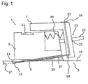
- a dermal access device 1 for fluid injection with a bearing block 3 for fixation of the dermal access device 1 onto the skin 5 of a patient and a slider 7 movably connected to the bearing block 3 are shown.
- a hollow needle 9 for puncturing the skin 5 is arranged at the slider 7, the needle being situated at least partly inside the slider 7.
- the hollow needle 9 is provided with a needle tip 11, which is provided with an angled cut 13 for an improved puncturing of the skin 5.
- the angled cut measures 15°.
- the needle tip 11 is the end of the hollow needle 9 which is facing away from the slider 7. Through the opening at the needle tip 11, the liquid can be injected into the skin 5.
- the hollow needle 9 is arranged at the slider 7, the slider 7 is movably connected to the bearing block 3 and the bearing block 3 is fixed in the patient's skin 5, the hollow needle 9 is puncturing the skin surface 15 when the slider 7 is moved in the first moving direction 35.
- the hollow needle 9 and the skin surface 15 are creating a puncture angle 17, which measures approximately 10° and thus not exceeds 25°.
- the dermal access device 1 is provided further with a fixation device 19, with which the bearing block 3 is fixable on the skin surface 15.
- the bearing block 3 is fixed on the skin surface 15 with its bottom side via the fixation device 19, so that the hollow needle 9 can safely puncture the skin 5 when the slider 7 is actuated. Further, unwanted forces acting on the dermal access device 1 from all directions are picked up by the fixation device 19 and are passed on to the skin 5.
- the dermal access device 1 is provided with a guidance device 21 for movably connecting slider 7 and bearing block 3.
- the guidance device 21 is provided with two guiding shafts 23 that are arranged on the bearing block. For reasons of visualisation only one of these guiding shafts is shown in Fig.1 .
- the slider 7 is provided with two loose bearings 25 implemented as cylindrical boreholes, which each correspond to one guiding shaft 23 of the guiding device 25.
- the guiding shafts 23 can slide through the loose bearings 25, which allows for a linear movement of the slider 7 relatively to the bearing block 3.
- the puncture angle 17 of the hollow needle 9 into the skin 5 is determined by the guidance device 21.
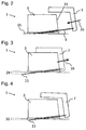
- Fig.2 shows a dermal access device 1 with a hollow needle 9 in the resting position, where the hollow needle 9 is arranged in a corresponding needle guidance device 27 of the bearing block 3.
- the hollow needle 9 is protected inside the needle guidance device 27 of the bearing block 3 when situated in the resting position.
- the needle tip 11 does not protrude from the bearing block 3.
- the danger of injury during handling the dermal access device 1 can be avoided.
- an unwanted puncturing by the hollow needle 9 can be prevented.
- Fig. 3 shows a dermal access device 1 with a hollow needle 9 in a first puncture position.
- a dermal access device 1 with a hollow needle 9 in a second puncture position is shown.
- the needle tip 11 is situated in the first and second puncture position inside the skin 5 of the patient, when applying the dermal access device 1 as intended.
- the first puncture position differs from the second puncture position by the positioning of the slider 7 relative to the bearing block 3.
- the needle tip 11 is distanced in a first distance 29 from the part of the dermal access device 1 that touches the skin (i.e. the bottom side of the fixation device 19).
- the needle tip 11 In the second puncture position, the needle tip 11 is distanced in a second distance 31 from the part of the dermal access device 1 that touches the skin, which measures 0.5 mm. In the second puncture position of the hollow needle 9, an intradermal injection can be given to the patient. As evident from Fig. 3 and 4 , the first distance 29 is greater than the second distance 31, so that the needle tip 11 in the first puncture position has a greater distance to the bearing block 3 than in the second puncture position.
- the dermal access device 1 is provided with a stop 33 implemented as a mechanical stop for the limitation of the first moving direction 35 of the slider 7 at the first puncture position of the hollow needle 9.
- the first moving direction 35 is the direction towards which the slider 7 needs to be pushed in order to bring the hollow needle 9 from the resting position into the first puncture position. Because of the first stop 33, the hollow needle 9 can only be moved from the resting position to the first puncture position but not further.
- the first stop is provided by the bearing block 3, which stops the movement of the slider 7 in the first moving direction 35 when it reaches the first puncture position.
- the dermal access device 1 is provided with a second stop 37, which is differing from the first stop 33 and is implemented as a second mechanical stop for limiting the second moving direction 39 of the slider 7 at a second puncture position of the hollow needle 9.
- the second moving direction 39 is the direction towards which the slider 7 needs to be moved in order to bring the hollow needle 9 from the first puncture position into the second puncture position.
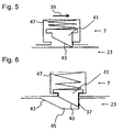
- the slider 7 is provided with a lock element 41 that has a sloping face 43 at one of the loose bearings 25.
- the guiding shaft 23 is further provided by a lock groove 45 with also a sloping face 43 which is corresponding to the lock element 41.
- the lock element 41 is pressed into the lock groove 45 via a spring 47, whereby the movement of the slider 7 is limited in the second moving direction.
- Fig. 6 wherein in Fig.6 a position of the slider 7 is pictured, where the hollow needle 9 is positioned in the second puncture position. Because of the sloping face 43 of the lock element 41 and the lock groove 45, the movement of the slider 7 towards the first moving direction is not limited by the lock groove and lock spring.
- the dermal access device 1 is further provided by a spring used as a readjusting device 49, by which the hollow needle 9 can be brought from the first to the second puncture position.
- a spring used as a readjusting device 49 by which the hollow needle 9 can be brought from the first to the second puncture position.
- an inspection device 51 implemented as a lens with cross lines, is arranged for viewing the puncture position of the hollow needle 9 into the skin 5. Because the inspection device 51 is implemented as a lens, it is possible to align the dermal access device 1 according to the structures on the skin surface 15, so that the puncture position of the hollow needle can be chosen in the optimum. The puncture position can also be observed during the injection procedure by using the inspection device.
- connection device 57 implemented as a flat area is arranged at the slider 7.
- the connection device 57 is arranged at that side of the slider 7 which is facing away from the skin surface 15. With the help of the connection device 57, a connection between the hollow needle 7 and the fluid reservoir 55 to be attached to will provided.
- a filter 59 is arranged at the connection device.
- the slider 7 is detachably fixed at the bearing block 3 in the second puncture position of the hollow needle 9.
- the lock element 41 as well as the lock groove is provided with a square shaped cross section, so that when reaching the second puncture position of the hollow needle 9, the slider 7 is neither movable towards the first 35 nor towards the second moving position 39.
- a not shown detachment mechanism is provided in order to detach the fixation.
- a retaining mechanism is arranged at the slider 7, in order to prevent an unwanted fixation of the slider 7 at the bearing block 3 during a movement in the first moving direction 35 from the resting position to the first injection position.
- the lock element 41 is pressed into the lock groove 45.
- the retaining mechanism is deactivated, so that the slider 7 can be fixed at the bearing block 3 via the lock element 41 and the lock groove 45 during the movement in the second moving direction 39.
- the retaining mechanism as well as the detachment mechanism is not shown in the Figures for reasons of visualisation.
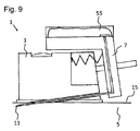
- the dermal access device 1 is provided by a fluid reservoir 55 for storing a liquid to be injected.
- the fluid reservoir 55 is implemented as a bag and inseparably connected to the slider 7.
Landscapes
- Health & Medical Sciences (AREA)
- Vascular Medicine (AREA)
- Engineering & Computer Science (AREA)
- Anesthesiology (AREA)
- Biomedical Technology (AREA)
- Heart & Thoracic Surgery (AREA)
- Hematology (AREA)
- Life Sciences & Earth Sciences (AREA)
- Animal Behavior & Ethology (AREA)
- General Health & Medical Sciences (AREA)
- Public Health (AREA)
- Veterinary Medicine (AREA)
- Infusion, Injection, And Reservoir Apparatuses (AREA)
Description
- The present invention concerns a dermal access device for fluid injection with a bearing block for fixation of the dermal access device onto the skin of a patient, a slider movably connected to the bearing block and a hollow needle arranged at the slider for puncturing the skin.
- The present invention further concerns a dermal access device for fluid injection with a bearing block for fixation of the dermal access device onto the skin of a patient, a movable slider connected to the bearing block and a hollow needle arranged at the slider for puncturing the skin, wherein the dermal access device is provided with a first stop for limiting a first moving direction of the slider at a first puncture position of the hollow needle.
- From the US-
document US 7 556 615 B2 , for example, a microneedle access device is known, which is provided with a protruding ring-shaped skin pre-stressing device. This skin pre-stressing device encloses the microneedle, and it touches the skin surface of the patient before puncturing the skin, shortly after the microneedle deformed the skin through contact. With the ring-shaped skin pre-stressing device, the deformation of the skin surface is minimized, which allows for a more precise penetration of the microneedle. - Further, from the international patent application publication
WO 2007/061972 A2 an access device for injectable substances is known, that is provided with a hollow needle of sufficient length in order to penetrate into the skin of a patient. The access device is provided with a delimiter for controlling the penetration depth of the hollow needle as well as a stabilizer that is positioned at a distance to the delimiter. Deformation of the tissue close to the puncture position is avoided with the stabilizer, so that the depth where the substance is introduced is essentially determined through the length of the hollow needle. - The US-document
US 2004/0147901 A1 discloses an intradermal application device, provided with a vacuum chamber in order to achieve an essentially flat puncture area for the hollow needle on the skin. The angle between the axis of the device and the skin is 45° in one embodiment, but can be every angle between 30° und 60° in other embodiments. - Further, from an international patent application publication
WO 2009/086463 A1 a device for applying a substance is known, which is provided with a sealed package with a squeezable reservoir, containing the substance. Further, a hollow needle is envisioned for the application of the substance, which is a therapeutic liquid. - The international patent application
WO 02/100457 A2 - The patent application
US 2008/0269687 A1 describes various patches for medical devices. An adhesive patch of a medical device may have selective areas with adhesive material of varying adhesion strengths. A medical device may include a pierceable membrane containing an agent, the pierceable membrane position to be pierced by a needle and to cause some of the agent to be carried to the user-patient. - In the UK patent application
GB 2436526 A - The United States patent
US 5,437,640 describes a device for guiding the insertion of a hypodermic, tuberculin or other needle and, more particularly for administering a Mantoux tuberculin test. The device comprises a platform having a channel extending therethrough sized to receive a flexible needle for guiding the insertion of the needle at a proscribed angle, direction and depth for the introduction or removal of fluids from the body. - The US patent application
US 2002/0077599 A1 discloses a low-profile inserter for an angled infusion set comprising an inserter housing having a bottom wall, a retainer slidably connected to the inserter housing for movement between retracted and extended position in a direction substantially parallel with the bottom wall and a base member connected to the inserter housing. The retainer is adapted to releasably receive a cannula assembly, including a cannula connected to a cannula housing. The base member has a lower surface that is adapted to contact a skin outer surface. - A novel device and method for intradermal delivery of an active agent is provided in the patent application
US 2007/0191780 A1 . The device comprises a housing, which contains a reservoir chamber. A flexible reservoir containing the active agent is placed in the chamber. Upon pressure on an actuator the active agents are delivered via a hollow needle to the skin. - The Australian patent
AU 8704582 A - An automated system and methods for delivery of a therapeutic or cosmetic substance into cutaneous, subcutaneous or intramuscular tissue is disclosed in the US patent application
US 2008/0167674 A1 . The system comprises a robotic arm which is image-guided by one or more cameras. A controller is used to precisely manoeuvre the arm in six degrees of freedom. When delivering a therapeutic or cosmetic substance into a target tissue, the delivery cannula can be retracted thus forming a track in the tissue. - The underlying problem of the invention is to provide a dermal access device that is improved compared to the state of the art. Particularly, the dermal access device shall provide a reliable and precise intradermal injection. Further, the injection with the dermal access device should be comfortable for the patient.
- The reference numbers in all claims have no limiting effect but only serve the purpose of improving readability.
- For solving the problem, the invention teaches a dermal access device with the features of
claim 1. A dermal access device for fluid injection is to be understood as an apparatus for injecting a liquid for medical purposes by means of a hollow needle that punctures the skin of a patient. In connection with the invention, the term injection of a liquid also comprises medical infusions of the liquid. With the help of an injection, active pharmaceutical ingredients, in particular medicaments, can be administered to the patient. For puncturing the skin of a patient, a hollow needle is usually provided with a needle tip. In the present invention, the needle tip is the end of the hollow needle which is facing away from the slider. Via an opening in the needle tip, the liquid can exit the needle during injection and is injected into the tissue. In order to facilitate the skin puncturing further, known hollow needles are cut at an angle at the tip. Due to the angled cut the hollow needle has a sharp angle at the needle tip, and the needle tip opening opens at a certain reach along the hollow needle. The cut's angle usually measures 15°. During the injection or infusion, the liquid can be passed from a fluid reservoir through the hollow needle to the needle's tip in order to be injected into the tissue of the patient. - Because the slider is movably connected to the bearing block, the movement of the slider relative to the bearing block can, advantageously, also move the hollow needle arranged at the slider relatively to the bearing block. By using the dermal access device as intended, the bearing block is fixed on the skin of a patient such that the slider will be moved relatively to the bearing block during an actuation and the hollow needle will punctuate the skin. Advantageously, the usage of the dermal access device is not restricted to the application of an intradermal injection, but can, in an appropriate embodiment, be utilized also for other types of injections as e.g. for a subcutaneous or an intramuscular injection, or an injection into the "junctional layer" as it is known to the person skilled in the art from e.g.
WO2004/098676A2 . The respective contents ofWO2004/098676A2 are part of the present disclosure by reference. The type of injection to be administered can, for example, be determined through the hollow needle length in order to be able to reach the designated tissue (e.g. epidermis, derma, subcutis). Advantageously, the desired type of injection can be realized through a purely mechanical system. - A stop in the sense of the present invention is a means for limiting in the designated use of the dermal access device the movement of the slider in at least one moving direction. In the first and second puncture position of the hollow needle according to the invention, the hollow needle is located at least partly inside the skin of the patient. In other words, the hollow needle tip is positioned in the first and second puncture position in such a way that the skin surface is located in between the needle tip and the dermal access device. Because of the fact that the slider is limited through the first stop at the first puncture position of the hollow needle in the first moving direction, advantageously, a further movement of the slider in the first moving direction can be prevented. In the first moving direction, the hollow needle can for example puncture the skin, where the maximum puncture depth into the skin is determined through the first stop. In other words, the hollow needle tip has the maximum puncture depth into the skin at the first puncture position.
- It is an achievable advantage of the second stop according to the invention that the bulge formed in the process of skin puncturing can be relaxed again in order to allow for a comfortable injection for the patient. By means of the second stop it is achievable that the hollow needle can be retracted a little towards the second moving direction after puncturing the skin with the hollow needle, which can relax the skin again. In other words, the dermal access device according to the invention permits at first during puncturing with the hollow needle the formation of a bulge, but afterwards this can, advantageously, be reduced or even completely removed through partial reversion of the puncturing process. Thus, a comfortable injection for the patient at the puncture position with relaxed skin can be achieved when the hollow needle is located at the second puncture position.
- Advantageous embodiments and improvements, which can be utilized individually or in combination with each other, are subject of the dependent claims.
- In a preferred embodiment of the invention, the hollow needle constitutes a puncture angle with the skin surface that does not exceed 25° when puncturing the skin, wherein the puncture angle more preferably matches the angle that the hollow needle constitutes with the skin surface in the first and/or second puncture position. More preferable, the puncture angle does not exceed 20°, more preferably not 15°. More preferable, the puncture angle measures between 5° and 15°. More preferably the puncture angle is approximately 10°, which can especially be suited for an intradermal injection. Advantageously, because of the puncture angle according to the invention, the hollow needle can be applied at such a puncture angle via the movement of the slider towards the first moving direction, which also a doctor would use for application of an intradermal injection. More preferably, the hollow needle tip is situated less than 1.5 mm beneath the skin surface during the injection, more preferable 1 mm or less. More preferably, the needle tip is situated more than 0.1 mm beneath the skin surface during the injection, more preferably 0.35 mm or more. Typically, the needle tip is situated approximately 0.5 mm beneath the skin surface. More preferably, the hollow needle is situated in the second puncture position during the injection. Further, with a puncture angle according to the invention, a long puncture channel can be obtained, so that a very good sealing of the hollow needle through the skin can be achieved. In this way, a leakage of the liquid through the puncture channel can be avoided during the injection.
- Because the hollow needle has a puncture angle which is not exceeding 25° with respect to the skin surface when puncturing the skin, it is achievable, that the dermal access device punctuates the skin at a puncture angle that also a doctor would choose, if e.g. he punctuates the skin with a hollow needle for an intradermal injection. Advantageously, the part of the skin above the subcutis can be reached reliably with the punctuation angle according to the invention, so that a reliable and precise intradermal injection is possible. An intradermal injection, in the sense of this invention is an injection in the part of the skin which is above the subcutis. Typically, the boundary between dermis (the skin layer above the subcutis) and the subcutis is situated in a depth of 1.5 to 2.5 mm; see e.g. Laurent A. et al., "Echographic measurement of skin thickness in adults by high frequency ultrasound to assess the appropriate microneedle length for intradermal delivery of vaccines", Vaccine, 2007, Vol. 25, Issue 34, pp. 6423-6430.
- For an intradermal injection via mechanical systems where the hollow needle normally punctures the skin at an angle of over 30°, when using the standard hollow needles, the difficulty arises that the liquid is leaking laterally at the puncture position as a result of a too shallow puncture depth of the needle tip and the lateral dimensions of the needle tip opening. This is usually solved by the usage of especially thin hollow needles, where the lateral dimensions of the needle tip opening are smaller than the puncture depth of the hollow needle. In contrary to that, advantageously, the puncture angle according to the invention is enabling an intradermal injection with a standard hollow needle that is e.g. available with a diameter of 0.3 mm. Then, because of the angle according to the invention, the length of the puncturing channel is large enough for the punctured skin to seal the puncturing hollow needle sufficiently from the puncture position to the needle tip opening. According to the invention, it can be exploited that the standard hollow needles are easier to fabricate or to purchase than specialized needles. Further, standard hollow needles can have a high stability, which can facilitate the handling of the hollow needle and/or the dermal access device
- A preferred stop is a mechanical stop. An elastic element for example (such as a rubber buffer or a spring) would also be possible as a stop, the elastic element preferably being positioned on the one side at the slider and on the other side at a part of the dermal access device or on the skin; more preferably for this purpose the elastic element is fixed on the slider and/or on the other a part of the dermal access device or on the skin or is being fabricated in on-piece with the slider or the other part. Such an elastic element could limit the movement of the slider, for example, via its preferred elongation (i.e. its elongation in the equilibrium state, when no external forces are acting on the elastic element) in order to provide the second stop. Also, such an elastic element could limit the movement of the slider, for example, via its maximum compression (when a spring cannot be compressed further, because all turns of the spring lie on top of each other or a protrusion has reached its maximum depth compressed in the rubber buffer) in order to provide the first stop.
- More preferably, by reaching the first stop, the slider is movable in other directions that are different from the first moving direction, more preferably in the second moving direction. In order to apply an injection, the hollow needle can be brought first in the first and then in the second puncture position, wherein the first puncture position differs from the second puncture position by the positioning of the slider relative to the bearing block. In a further more preferred embodiment of the invention, by reaching the second stop, the slider is movable in other directions that are different to the second moving direction, more preferably in the first moving direction.
- In a further embodiment of the invention, at least two hollow needles are arranged at the slider. This way it is achievable, that the liquid is not injected punctually but is distributed over an area. Advantageously, this area can be determined by the hollow needles arranged at the slider.
- In an embodiment of the invention, the slider position is fixable relatively to the bearing block in the second puncture position of the hollow needle. More preferably, the slider position is detachably fixable relatively to the bearing block in the second puncture position of the hollow needle. More preferably, the slider position is detachably fixable by means of a lock mechanism relatively to the bearing block. In this way, it is achievable that the hollow needle is not movable in the skin in the second puncture position, the more so as the dermal access device according to the invention is fixed on the patient's skin. This can allow for a more comfortable injection for the patient. Further, through the fixation of the slider in the second puncture position of the hollow needle, it can be avoided that the hollow needle is pulled out of the skin accidentally. Advantageously, the fixation of the hollow needle in the second position is detachable, so that the hollow needle can be removed from the skin after applying the injection.
- According to the invention, it is envisioned, that the hollow needle is provided with a needle tip, and that the needle tip has a greater distance to the bearing block in the first puncture position than in the second puncture position. More preferably, the needle tip in the first puncture position has a first distance to the bearing block and in the second puncture position a second distance. More preferably, the first distance is greater than the second distance. Advantageously, this allows for an injection spot near the skin surface to enable an intradermal injection. Here, the injection spot is the location, where the needle tip is located inside the skin during the injection.
- In a preferred embodiment of the invention, the dermal access device is provided with a guidance device for the movable connection of slider and bearing block. Advantageously, the guidance device can determine how the slider is moving relative to the bearing block, and how the hollow needle will puncture the skin. In other words, the guidance device can define the trajectory which the hollow needle follows during movement of the slider. With the help of the guidance device, the puncture angle of the hollow needle and the patients' skin can also be determined. More preferably, the guidance device is provided with at least one guiding shaft, more preferable with at least two guiding shafts. More preferably, at least one guiding shaft is arranged at the bearing block. More preferably, the slider is provided with at least one loose bearing that corresponds with the guiding shaft of the guiding device. More preferably, the number of loose bearings arranged at the slider equals the number of guiding shafts at the guiding device. Advantageously, with the help of the guiding shaft, a linear movement of the slider and the hollow needle relative to the bearing block or respectively to the patient's skin is possible. Of course, the invention also comprises embodiments, where at least one guiding shaft is arranged at the slider and at least one loose bearing is arranged at the bearing block. The invention also comprises embodiments, where at least one guiding shaft is arranged at the slider and at least one guiding shaft is arranged at the bearing block, and according to the guiding shafts, sliders and bearing blocks are provided with loose bearings correspondingly.
- In a further preferred embodiment, the dermal access device is provided with a readjusting device, by which the hollow needle can be repositioned from the first to the second puncture position. More preferably, the readjusting device is provided by an elastic element. The elastic element can provide one or more stops at the same time. The elastic element can be for example a rubber buffer or a spring.
- Advantageously, the hollow needle is automatically, without any interaction of the user, brought to the second puncture position via the readjusting device, when it reaches the first puncture position. More preferably, only when reaching the first puncture position, the readjusting device can reposition the hollow needle from the first to the second puncture position. More preferably, the readjusting device is arranged at the bearing block and acts on the slider. Because the readjusting device is acting on the slider, force effects on the hollow needle, which is in general more sensitive mechanically, are diminished. The rubber buffer is preferably composed of an elastic material, more preferably a thermoplastic elastomer. It is possible to fabricate the rubber buffer and the bearing block in one piece, e.g. by means of a two component injection moulding. In a more preferred embodiment of the invention, the slider is provided with one or more protrusions, e.g. realized through one or more knobs. The protrusion or the protrusions are pressed inside the rubber buffer, when the slider is brought into the first position. Preferably, the rubber buffer is pushing out the protrusions during a following disengagement in order to bring the slider to the second puncture position.
- In an embodiment of the invention, the bearing block and the slider are individual parts. There are also possible embodiments of the inventions, where bearing block and slider are produced in one piece, e.g. by means of injection moulding; in this respect, it is only important that the bearing block component and the slider component of the piece can be moved relatively to each other, which is e.g. achievable, if bearing block and slider are connected via at least one flexure hinge, so that bearing block, slider and flexure hinge are one component. Also, in an advantageous embodiment of the invention, lock and detach mechanisms, e.g. lock nose and lock tongue, can be provided in one piece with their assigned components, in particular the bearing block and respectively the slider, where appropriate with one or more flexure hinges. Thus, it is advantageously achievable, that the system of bearing block, slider, lock and detach mechanisms can be fabricated in a few injection moulding steps or only in one injection moulding process.
- Preferably, it is envisioned according to the invention that the hollow needle can be positioned in a resting position, and that the hollow needle is arranged within a corresponding needle guidance device of the bearing block in the resting position. More preferably, the hollow needle is stored in the dermal access device in the resting position. Advantageously, the hollow needle can be protected from mechanical influences in the resting position by the needle guidance device. Further, because the hollow needle is arranged inside the needle guidance device, the risk of injuries during usage of the dermal access device, due to a protruding needle tip, can be avoided. Further, it is achievable, that the bearing block can be first seated on the skin without having the hollow needle already puncturing the skin. Advantageously, by actuating the dermal access device, the hollow needle can exit the needle guidance device and can be punctured into the skin. More preferably, the hollow needle is exiting the bearing block on the lower surface that is fixed on the patients' skin.
- More preferably, the hollow needle is situated at least partly inside the slider. Inside the slider a fluid channel can be created, through which the liquid can be transported from a fluid reservoir to the hollow needle and through the needle to the needle tip in order to be injected there. More preferably, the hollow needle protrudes a certain distance into the slider, where the fluid channel connects to. The path of the liquid in the slider preferably has a bent or buckled shape, which allows for a space saving dermal access device. For example, the channel inside the slider can be attached to the end of the hollow needle at an angle.
- To further improve the invention, it is preferably envisioned that the dermal access device is provided by a fixation device, by which the bearing block is fixed onto the skin surface. More preferably, the bearing block can be fixed via the fixation device with the lower surface onto the skin surface. With the fixation device, it is achievable that unwanted forces on the dermal access device from all directions can be picked up and are passed to the skin. Further, with a suitable fixation device, the bulging of the skin can be reduced during puncturing with the hollow needle into the skin. A fixation device according to the invention can e.g. be provided by double sided tape and/or a fixation band-aid. The fixation device can also have wings that are arranged at the sides of the bearing block. The wings could e.g. be fixed with a fixation band-aid onto the skin. A further example of a possible fixation device could also be a band, similar to the band of a wrist watch, bound around the corresponding part of the body. Of course, combinations of the discussed examples are possible.
- In a further preferred embodiment, an inspection device is arranged at the bearing block for viewing the puncture position of the hollow needle. More preferably, the inspection device is situated on the top side of the bearing block. More preferably, the inspection device is provided with a lens. More preferably, cross lines are arranged on the lens. Advantageously, with the inspection device, a selection and/or a precise determination of the puncture position is possible. The dermal access device can, advantageously, be positioned according to the skin structures, so that an optimal puncture position is achievable. Apart from the choice of the optimal puncture position, the puncture position can be observed during the injection process, in order to take appropriate actions in the case of complications.
- To further improve the invention, it is preferably envisioned that a connection device is arranged at the slider, in order to combine the hollow needle and with a fluid reservoir. The connection device can also be described as fluidic connection. More preferably, the connection device is situated at the end of the hollow needle which is facing away from the needle tip. More preferably, the connection device is arranged at that side of the slider which is facing away from the skin surface. The connection device can e.g. be an even area where a fluid reservoir can be bonded to. Further possible embodiments of the connection device can be a luer-lock connector, a simple cone or a tube clip. There are possible other embodiments, that have connection devices, which connect the hollow needle tightly with a tubing, that leads to a fluid reservoir.
- In a preferred embodiment of the invention, the connection device is provided with a filter. By using a filter, it can be avoided that dirt particles clog the hollow needle or even get injected into the skin.
- According to the invention it is preferably envisioned, that the dermal access device is provided with a fluid reservoir for storing the fluid to be injected. In this way, a complete injection system can be provided. More preferably, the fluid reservoir is provided as a bag. More preferably, the fluid reservoir is connected to the slider. More preferably, the fluid reservoir is connected inseparablely to the slider.
- Further advantageous embodiments will be described in detail in the following with the help of drawings containing three exemplary embodiments, which the invention is not limited to.
- Schematically it is shown in:
-
Fig.1 a dermal access device in a sectional view; -
Fig.2 a dermal access device with a hollow needle in resting position; -
Fig. 3 a dermal access device with a hollow needle in a first puncture position; -
Fig. 4 a dermal access device with a hollow needle in a second puncture position; -
Fig. 5 a section of slider and guiding shaft; -
Fig. 6 a section of slider and guiding shaft in the second puncture position of the slider; -
Fig. 7 a section of slider and guiding shaft; -
Fig. 8 a section of slider and guiding shaft in the second puncture position of the slider;
and finally -
Fig. 9 a dermal access device with a fluid reservoir in a sectional view. - In the following description of three preferred embodiments of the present invention, the same reference numbers denote the same or comparable components.
- The exemplary embodiment will be explained in the following with the help of
Fig. 1-6 . InFig.1 adermal access device 1 for fluid injection with abearing block 3 for fixation of thedermal access device 1 onto theskin 5 of a patient and aslider 7 movably connected to thebearing block 3 are shown. Ahollow needle 9 for puncturing theskin 5 is arranged at theslider 7, the needle being situated at least partly inside theslider 7. Thehollow needle 9 is provided with aneedle tip 11, which is provided with anangled cut 13 for an improved puncturing of theskin 5. The angled cut measures 15°. Theneedle tip 11 is the end of thehollow needle 9 which is facing away from theslider 7. Through the opening at theneedle tip 11, the liquid can be injected into theskin 5. Because thehollow needle 9 is arranged at theslider 7, theslider 7 is movably connected to thebearing block 3 and thebearing block 3 is fixed in the patient'sskin 5, thehollow needle 9 is puncturing theskin surface 15 when theslider 7 is moved in the first movingdirection 35. When puncturing theskin 5, thehollow needle 9 and theskin surface 15 are creating apuncture angle 17, which measures approximately 10° and thus not exceeds 25°. By using thissmall puncture angle 17, in particular, the skin layers above the subcutis can reliably be reached in order to be able to inject the fluid to be applied intradermally. - The
dermal access device 1 is provided further with afixation device 19, with which thebearing block 3 is fixable on theskin surface 15. Thebearing block 3 is fixed on theskin surface 15 with its bottom side via thefixation device 19, so that thehollow needle 9 can safely puncture theskin 5 when theslider 7 is actuated. Further, unwanted forces acting on thedermal access device 1 from all directions are picked up by thefixation device 19 and are passed on to theskin 5. - Further, the
dermal access device 1 is provided with aguidance device 21 for movably connectingslider 7 andbearing block 3. Here, theguidance device 21 is provided with two guidingshafts 23 that are arranged on the bearing block. For reasons of visualisation only one of these guiding shafts is shown inFig.1 . Theslider 7 is provided with twoloose bearings 25 implemented as cylindrical boreholes, which each correspond to one guidingshaft 23 of the guidingdevice 25. The guidingshafts 23 can slide through theloose bearings 25, which allows for a linear movement of theslider 7 relatively to thebearing block 3. Further, thepuncture angle 17 of thehollow needle 9 into theskin 5 is determined by theguidance device 21. -
Fig.2 shows adermal access device 1 with ahollow needle 9 in the resting position, where thehollow needle 9 is arranged in a correspondingneedle guidance device 27 of thebearing block 3. Thehollow needle 9 is protected inside theneedle guidance device 27 of thebearing block 3 when situated in the resting position. In particular, theneedle tip 11 does not protrude from thebearing block 3. Thus, the danger of injury during handling thedermal access device 1 can be avoided. Further, during seating of thebearing block 3 onto theskin 5, an unwanted puncturing by thehollow needle 9 can be prevented. -
Fig. 3 shows adermal access device 1 with ahollow needle 9 in a first puncture position. InFig. 4 adermal access device 1 with ahollow needle 9 in a second puncture position is shown. As evident fromFig. 3 and 4 , theneedle tip 11 is situated in the first and second puncture position inside theskin 5 of the patient, when applying thedermal access device 1 as intended. The first puncture position differs from the second puncture position by the positioning of theslider 7 relative to thebearing block 3. In the first puncture position, theneedle tip 11 is distanced in afirst distance 29 from the part of thedermal access device 1 that touches the skin (i.e. the bottom side of the fixation device 19). In the second puncture position, theneedle tip 11 is distanced in asecond distance 31 from the part of thedermal access device 1 that touches the skin, which measures 0.5 mm. In the second puncture position of thehollow needle 9, an intradermal injection can be given to the patient. As evident fromFig. 3 and 4 , thefirst distance 29 is greater than thesecond distance 31, so that theneedle tip 11 in the first puncture position has a greater distance to thebearing block 3 than in the second puncture position. - The
dermal access device 1 is provided with astop 33 implemented as a mechanical stop for the limitation of the first movingdirection 35 of theslider 7 at the first puncture position of thehollow needle 9. Here, the first movingdirection 35 is the direction towards which theslider 7 needs to be pushed in order to bring thehollow needle 9 from the resting position into the first puncture position. Because of thefirst stop 33, thehollow needle 9 can only be moved from the resting position to the first puncture position but not further. The first stop is provided by thebearing block 3, which stops the movement of theslider 7 in the first movingdirection 35 when it reaches the first puncture position. Further, thedermal access device 1 is provided with asecond stop 37, which is differing from thefirst stop 33 and is implemented as a second mechanical stop for limiting the second movingdirection 39 of theslider 7 at a second puncture position of thehollow needle 9. The second movingdirection 39 is the direction towards which theslider 7 needs to be moved in order to bring thehollow needle 9 from the first puncture position into the second puncture position. - In
Fig. 5 and 6 the mechanism by which thesecond stop 37 is implemented is sketched. Here, theslider 7 is provided with alock element 41 that has a slopingface 43 at one of theloose bearings 25. The guidingshaft 23 is further provided by alock groove 45 with also a slopingface 43 which is corresponding to thelock element 41. When the slider is moved from the first puncture position towards the second movingdirection 39, with reaching the second puncture position, thelock element 41 is pressed into thelock groove 45 via aspring 47, whereby the movement of theslider 7 is limited in the second moving direction. This is shown inFig. 6 , wherein inFig.6 a position of theslider 7 is pictured, where thehollow needle 9 is positioned in the second puncture position. Because of the slopingface 43 of thelock element 41 and thelock groove 45, the movement of theslider 7 towards the first moving direction is not limited by the lock groove and lock spring. - The
dermal access device 1 is further provided by a spring used as a readjustingdevice 49, by which thehollow needle 9 can be brought from the first to the second puncture position. As a result of the readjusting device, which is arranged at thebearing block 3 and is acting on theslider 7, theslider 7 is automatically brought to the second puncture position, meaning without further interaction of the user. Thus, the user does not need to pull back theslider 7 after reaching the first stop. - At the
bearing block 3, aninspection device 51 implemented as a lens with cross lines, is arranged for viewing the puncture position of thehollow needle 9 into theskin 5. Because theinspection device 51 is implemented as a lens, it is possible to align thedermal access device 1 according to the structures on theskin surface 15, so that the puncture position of the hollow needle can be chosen in the optimum. The puncture position can also be observed during the injection procedure by using the inspection device. - In order to combine the
hollow needle 9, which is partly situated inside of theslider 7 and shows abent profile 53, with afluid reservoir 55, aconnection device 57 implemented as a flat area is arranged at theslider 7. Theconnection device 57 is arranged at that side of theslider 7 which is facing away from theskin surface 15. With the help of theconnection device 57, a connection between thehollow needle 7 and thefluid reservoir 55 to be attached to will provided. In order to filter possible contamination out of the fluid to be injected, afilter 59 is arranged at the connection device. - In a second exemplary embodiment, shown in
Fig. 7 and 8 , that otherwise does not differ from the first exemplary embodiment, theslider 7 is detachably fixed at thebearing block 3 in the second puncture position of thehollow needle 9. Here, thelock element 41 as well as the lock groove is provided with a square shaped cross section, so that when reaching the second puncture position of thehollow needle 9, theslider 7 is neither movable towards the first 35 nor towards the second movingposition 39. This is shown inFig. 8 . In order to detach the fixation a not shown detachment mechanism is provided. A retaining mechanism is arranged at theslider 7, in order to prevent an unwanted fixation of theslider 7 at thebearing block 3 during a movement in the first movingdirection 35 from the resting position to the first injection position. With the help of the retaining mechanism it is avoided, that thelock element 41 is pressed into thelock groove 45. As soon as the first puncture position is reached, the retaining mechanism is deactivated, so that theslider 7 can be fixed at thebearing block 3 via thelock element 41 and thelock groove 45 during the movement in the second movingdirection 39. The retaining mechanism as well as the detachment mechanism is not shown in the Figures for reasons of visualisation. - In a third exemplary embodiment, shown in
Fig.9 , which otherwise does not differ from the first and second exemplary embodiment, thedermal access device 1 is provided by afluid reservoir 55 for storing a liquid to be injected. Thefluid reservoir 55 is implemented as a bag and inseparably connected to theslider 7. - The disclosed features as described in the above description, claims and Figures can be of importance for the realisation of the invention in its different embodiments in any combination as well as individually.
-
- 1 3
- bearing block
- 5
- skin
- 7
- slider
- 9
- hollow needle
- 11
- needle tip
- 13
- sharpened cut
- 15
- skin surface
- 17
- puncture angle
- 19
- fixation device
- 21
- guidance device
- 23
- guidance shaft
- 25
- loose bearing
- 27
- needle giudance device
- 29
- first distance
- 31
- second distance
- 33
- first stop
- 35
- first moving direction
- 37
- second stop
- 39
- second moving direction
- 41
- lock-element
- 43
- sloping face
- 45
- lock groove
- 47
- spring
- 49
- readjusting device
- 51
- inspection device
- 53
- bent profile
- 55
- fluid reservoir
- 57
- connection device
- 59
- filter
Claims (11)
- A dermal access device (1) for fluid injection with a bearing block (3) for fixation of the dermal access device (1) onto the skin (5) of a patient, a movable slider (7) connected to the bearing block (3) and a hollow needle (9) arranged at the slider (7) for puncturing the skin (5), the needle (9) comprising a needle tip (11), wherein the dermal access device (1) is provided with a first stop (33) for limiting a first moving direction (35) of the slider (7) at a first puncture position of the hollow needle (9), wherein the dermal access device (1) is provided with a second stop (37), differing from the first stop (33), for limiting a second moving direction (39) of the slider (7), wherein the second stop (37) is at a second puncture position of the hollow needle (9), in which second puncture position an injection can be given to the patient, and wherein the slider (7) is moveable in the first moving direction from a resting position to the first stop (33) and in the second moving direction from the first stop (33) at the first puncture position to the second stop (37) at the second puncture position such that the needle tip (11) in the first puncture position has a greater distance to the bearing block (3) than in the second puncture position.
- A dermal access device (1) according to claim 1, characterized in that the hollow needle (9) constitutes a puncture angle (17) with respect to the skin surface (15) when puncturing the skin (5), which is not exceeding 25°.
- A dermal access device (1) according to claim 1 or 2, characterized in that the position of the slider (7) is fixable relatively to the bearing block (3) at the second puncture position of the hollow needle (9).
- A dermal access device (1) according to one of the previous claims, characterized in that the dermal access device (1) is provided with a guidance device (21) for the movable connection of slider (7) and bearing block (3).
- A dermal access device (1) according to one of the previous claims, characterized in that the dermal access device (1) is provided with a readjusting device (49), by which the hollow needle (9) can be repositioned from the first to the second puncture position.
- A dermal access device (1) according to one of the previous claims, characterized in that the hollow needle (9) can be positioned in a resting position, and that the hollow needle (9) is arranged within a corresponding needle guidance device (27) for the hollow needle (9) of the a bearing block (3) in the resting position.
- A dermal access device (1) according to one of the previous claims, characterized in that the dermal access device (1) is provided with a fixation device (19) by which the bearing block (3) is fixed onto the skin surface (15).
- A dermal access device (1) according to one of the previous claims, characterized in that the bearing block (3) is provided with an inspection device (51) for viewing the puncture position of the hollow needle (9).
- A dermal access device (1) according to one of the previous claims, characterized in that the slider (7) is provided with a connection device (57) in order to combine the hollow needle (9) with a fluid reservoir (55).
- A dermal access device (1) according to claim 9, characterized in that the connection device (57) is provided with a filter (59).
- A dermal access device (1) according to one of the previous claims, characterized in that the dermal access device (1) is provided with a fluid reservoir (55) for the storage of a fluid that will be injected.
Applications Claiming Priority (2)
| Application Number | Priority Date | Filing Date | Title |
|---|---|---|---|
| DE102010001506A DE102010001506A1 (en) | 2010-02-02 | 2010-02-02 | Dermal access device |
| PCT/EP2011/051421 WO2011095494A1 (en) | 2010-02-02 | 2011-02-01 | Dermal access device |
Publications (2)
| Publication Number | Publication Date |
|---|---|
| EP2531242A1 EP2531242A1 (en) | 2012-12-12 |
| EP2531242B1 true EP2531242B1 (en) | 2016-11-02 |
Family
ID=44059084
Family Applications (1)
| Application Number | Title | Priority Date | Filing Date |
|---|---|---|---|
| EP11702180.8A Not-in-force EP2531242B1 (en) | 2010-02-02 | 2011-02-01 | Dermal access device |
Country Status (9)
| Country | Link |
|---|---|
| US (1) | US9174006B2 (en) |
| EP (1) | EP2531242B1 (en) |
| JP (1) | JP5568646B2 (en) |
| CN (1) | CN102905746B (en) |
| AU (1) | AU2011212481B2 (en) |
| CA (1) | CA2788738C (en) |
| DE (1) | DE102010001506A1 (en) |
| ES (1) | ES2613034T3 (en) |
| WO (1) | WO2011095494A1 (en) |
Families Citing this family (18)
| Publication number | Priority date | Publication date | Assignee | Title |
|---|---|---|---|---|
| US9950109B2 (en) * | 2010-11-30 | 2018-04-24 | Becton, Dickinson And Company | Slide-activated angled inserter and cantilevered ballistic insertion for intradermal drug infusion |
| BE1020202A3 (en) * | 2011-08-25 | 2013-06-04 | Intravascular I C T Consult Cooeperatieve Vennootschap Met Beperkte Aansprakelijkheid | A TOOL FOR INSERTING A NEEDLE INTO A BODY PART, METHODS FOR ORIENTING A NEEDLE TO BE INSERTED INTO A BODY PART AND INSERTING THEREOF AND A FABRIC. |
| JP6068057B2 (en) * | 2012-08-24 | 2017-01-25 | 南部化成株式会社 | Transdermal dosing device and chemical injection needle used in the device |
| EP3068472B1 (en) * | 2013-11-14 | 2020-03-04 | Hahn-Schickard-Gesellschaft für angewandte Forschung e.V. | Access device |
| US10507038B2 (en) * | 2014-11-12 | 2019-12-17 | Civco Medical Instruments Co., Inc. | Needle guide devices for mounting on imaging transducers or adaptors on imaging transducer, imaging transducers for mounting needle guide devices and adaptors for imaging transducers for mounting needle guide devices thereon |
| DE102015107613A1 (en) | 2015-05-13 | 2016-11-17 | Hahn-Schickard-Gesellschaft für angewandte Forschung e.V. | Attachment for or on a device for injecting a liquid into or under the skin |
| US10603445B2 (en) | 2016-06-09 | 2020-03-31 | Becton, Dickinson And Company | Needle actuator assembly for drug delivery system |
| US10792432B2 (en) | 2016-06-09 | 2020-10-06 | Becton, Dickinson And Company | Drive assembly and spacer for drug delivery system |
| US10751476B2 (en) | 2016-06-09 | 2020-08-25 | Becton, Dickinson And Company | Actuator assembly for drug delivery system |
| US10549044B2 (en) | 2016-06-09 | 2020-02-04 | Becton, Dickinson And Company | Spacer assembly for drug delivery system |
| EP4397336A3 (en) | 2017-10-16 | 2024-10-09 | Becton, Dickinson and Company | Spacer assembly for drug delivery device |
| CN110075387B (en) * | 2019-06-10 | 2024-06-07 | 河南驼人医疗器械集团有限公司 | Needle-prick-preventing remaining needle capable of observing needle withdrawal distance |
| US11065461B2 (en) | 2019-07-08 | 2021-07-20 | Bioness Inc. | Implantable power adapter |
| CN110559053B (en) * | 2019-09-12 | 2022-07-26 | 山东大学齐鲁医院 | Spinal surgery needle locator |
| US12357804B2 (en) | 2021-03-01 | 2025-07-15 | Deka Products Limited Partnership | Medical agent dispensing systems, methods, and apparatuses |
| US12161832B2 (en) | 2021-03-01 | 2024-12-10 | Deka Products Limited Partnership | Medical agent dispensing systems, methods, and apparatuses |
| MX2023010227A (en) * | 2021-03-01 | 2024-02-27 | Deka Products Lp | MEDICAL AGENT DISPENSING APPARATUS, SYSTEMS AND METHODS. |
| US12186470B1 (en) * | 2023-04-20 | 2025-01-07 | Navigator Medical, LLC | Medical needle placement device and methods of using the same |
Citations (1)
| Publication number | Priority date | Publication date | Assignee | Title |
|---|---|---|---|---|
| US20080167674A1 (en) * | 2007-01-08 | 2008-07-10 | Restoration Robotics, Inc. | Automated delivery of a therapeutic or cosmetic substance to cutaneous, subcutaneous and intramuscular tissue regions |
Family Cites Families (31)
| Publication number | Priority date | Publication date | Assignee | Title |
|---|---|---|---|---|
| DE1055760B (en) * | 1956-10-10 | 1959-04-23 | Robert Behringer | Automatic injection device |
| AU8704582A (en) | 1982-03-15 | 1983-09-22 | Ralph Franco | Aid for inserting needle |
| US4512768A (en) * | 1982-09-10 | 1985-04-23 | Avvari Rangaswamy | Analgesic syringe |
| JP2712189B2 (en) | 1987-09-08 | 1998-02-10 | ソニー株式会社 | Modem device |
| JPH0613741Y2 (en) * | 1987-10-26 | 1994-04-13 | 住友ベークライト株式会社 | Tube with medical puncture needle |
| JPH0613850A (en) | 1992-06-29 | 1994-01-21 | Nec Ic Microcomput Syst Ltd | Semiconductor integrated circuit |
| JPH0613850U (en) * | 1992-07-28 | 1994-02-22 | 川澄化学工業株式会社 | IVH catheter with filter |
| WO1995007722A1 (en) * | 1993-09-14 | 1995-03-23 | North Shore Laboratories Pty. Ltd. | Injection device |
| US5437640A (en) | 1994-01-31 | 1995-08-01 | Schwab; Louis | Apparatus and method for inserting hypodermic, tuberculin and other needles and for administering Mantoux tuberculin tests |
| US6607509B2 (en) | 1997-12-31 | 2003-08-19 | Medtronic Minimed, Inc. | Insertion device for an insertion set and method of using the same |
| US7052483B2 (en) * | 2000-12-19 | 2006-05-30 | Animas Corporation | Transcutaneous inserter for low-profile infusion sets |
| US20050010193A1 (en) | 2002-05-06 | 2005-01-13 | Laurent Philippe E. | Novel methods for administration of drugs and devices useful thereof |
| EP1432466B1 (en) | 2001-09-12 | 2012-08-15 | Becton, Dickinson and Company | Microneedle-based pen device for drug delivery and method for using same |
| GB0204640D0 (en) | 2002-02-27 | 2002-04-10 | Torsana Diabetes Diagnostics A | Injection apparatus |
| WO2003088835A2 (en) | 2002-04-19 | 2003-10-30 | Pelikan Technologies, Inc. | Method and apparatus for penetrating tissue |
| WO2004004803A2 (en) | 2002-07-08 | 2004-01-15 | Medical Instill Technologies, Inc. | Interadermal delivery device, and method of intradermal delivery |
| US20040247902A1 (en) | 2003-06-09 | 2004-12-09 | Chuang Hai Tung | Method for producing a fire-resistant laminated veneer-covering product and the product produced thereby |
| WO2005046769A2 (en) * | 2003-11-12 | 2005-05-26 | Vidacare Corporation | Reusable intraosseous device and method for accessing bone marrow in the sternum |
| IL178557A0 (en) | 2005-10-19 | 2007-02-11 | Animas Corp | Safety infusion set |
| WO2007052662A1 (en) | 2005-10-31 | 2007-05-10 | Terumo Kabushiki Kaisha | Puncture device, dosing device and puncture method |
| US7842008B2 (en) | 2005-11-21 | 2010-11-30 | Becton, Dickinson And Company | Intradermal delivery device |
| JP4768415B2 (en) | 2005-11-24 | 2011-09-07 | テルモ株式会社 | Puncture device |
| US20070191780A1 (en) | 2006-02-16 | 2007-08-16 | Pankaj Modi | Drug delivery device |
| GB2436526B (en) * | 2006-03-29 | 2010-01-27 | Arash Bakhtyari-Nejad-Esfahani | Syringe |
| EP1917990A1 (en) | 2006-10-31 | 2008-05-07 | Unomedical A/S | Infusion set |
| US8323250B2 (en) | 2007-04-30 | 2012-12-04 | Medtronic Minimed, Inc. | Adhesive patch systems and methods |
| EP2200684B1 (en) | 2007-08-17 | 2016-10-05 | Medtronic MiniMed, Inc. | Injection apparatus for making an injection at a predetermined depth in the skin |
| US8303545B2 (en) * | 2007-09-07 | 2012-11-06 | Stat Medical Devices, Inc. | Infusion device and method of using and making the same |
| JP2011508634A (en) | 2007-12-28 | 2011-03-17 | アクティヴパック, インコーポレイテッド | Dispenser and treatment package suitable for administration of therapeutic agents to patients |
| WO2011034516A1 (en) * | 2009-09-15 | 2011-03-24 | Becton, Dickinson And Company | Self-injection device |
| US8795230B2 (en) * | 2010-11-30 | 2014-08-05 | Becton, Dickinson And Company | Adjustable height needle infusion device |
-
2010
- 2010-02-02 DE DE102010001506A patent/DE102010001506A1/en not_active Ceased
-
2011
- 2011-02-01 EP EP11702180.8A patent/EP2531242B1/en not_active Not-in-force
- 2011-02-01 JP JP2012550477A patent/JP5568646B2/en not_active Expired - Fee Related
- 2011-02-01 AU AU2011212481A patent/AU2011212481B2/en not_active Ceased
- 2011-02-01 WO PCT/EP2011/051421 patent/WO2011095494A1/en not_active Ceased
- 2011-02-01 CN CN201180016473.5A patent/CN102905746B/en not_active Expired - Fee Related
- 2011-02-01 US US13/576,562 patent/US9174006B2/en not_active Expired - Fee Related
- 2011-02-01 ES ES11702180.8T patent/ES2613034T3/en active Active
- 2011-02-01 CA CA2788738A patent/CA2788738C/en not_active Expired - Fee Related
Patent Citations (1)
| Publication number | Priority date | Publication date | Assignee | Title |
|---|---|---|---|---|
| US20080167674A1 (en) * | 2007-01-08 | 2008-07-10 | Restoration Robotics, Inc. | Automated delivery of a therapeutic or cosmetic substance to cutaneous, subcutaneous and intramuscular tissue regions |
Also Published As
| Publication number | Publication date |
|---|---|
| JP5568646B2 (en) | 2014-08-06 |
| DE102010001506A1 (en) | 2011-08-04 |
| US9174006B2 (en) | 2015-11-03 |
| CN102905746B (en) | 2014-11-26 |
| CN102905746A (en) | 2013-01-30 |
| US20130041318A1 (en) | 2013-02-14 |
| JP2013518609A (en) | 2013-05-23 |
| AU2011212481A1 (en) | 2012-08-23 |
| EP2531242A1 (en) | 2012-12-12 |
| WO2011095494A1 (en) | 2011-08-11 |
| CA2788738C (en) | 2016-06-14 |
| ES2613034T3 (en) | 2017-05-22 |
| CA2788738A1 (en) | 2011-08-11 |
| AU2011212481B2 (en) | 2013-08-22 |
Similar Documents
| Publication | Publication Date | Title |
|---|---|---|
| AU2011212481B2 (en) | Dermal access device | |
| US10729844B2 (en) | Angled inserter for drug infusion | |
| EP2968891B1 (en) | Automatic angled infusion set assembly | |
| EP2456491B1 (en) | Intradermal injection adapter | |
| US7998119B2 (en) | System and method for delivering fluid into flexible biological barrier | |
| JP2010524646A (en) | Method and apparatus for intradermal injection | |
| MXPA06010227A (en) | Intradermal syringe and needle assembly. | |
| US20160296715A1 (en) | Access device | |
| US8007466B2 (en) | System and method for delivering fluid into flexible biological barrier | |
| WO2008139303A2 (en) | A novel device for intradermal injection | |
| US8876764B2 (en) | Intradermal pen adapter | |
| US20180369552A1 (en) | Device and method |
Legal Events
| Date | Code | Title | Description |
|---|---|---|---|
| PUAI | Public reference made under article 153(3) epc to a published international application that has entered the european phase |
Free format text: ORIGINAL CODE: 0009012 |
|
| 17P | Request for examination filed |
Effective date: 20120830 |
|
| AK | Designated contracting states |
Kind code of ref document: A1 Designated state(s): AL AT BE BG CH CY CZ DE DK EE ES FI FR GB GR HR HU IE IS IT LI LT LU LV MC MK MT NL NO PL PT RO RS SE SI SK SM TR |
|
| DAX | Request for extension of the european patent (deleted) | ||
| 17Q | First examination report despatched |
Effective date: 20140721 |
|
| REG | Reference to a national code |
Ref country code: DE Ref legal event code: R079 Ref document number: 602011031859 Country of ref document: DE Free format text: PREVIOUS MAIN CLASS: A61M0005320000 Ipc: A61M0005158000 |
|
| GRAP | Despatch of communication of intention to grant a patent |
Free format text: ORIGINAL CODE: EPIDOSNIGR1 |
|
| RIC1 | Information provided on ipc code assigned before grant |
Ipc: A61M 5/20 20060101ALI20160415BHEP Ipc: A61M 5/46 20060101ALI20160415BHEP Ipc: A61M 5/142 20060101ALI20160415BHEP Ipc: A61M 5/158 20060101AFI20160415BHEP Ipc: A61M 5/32 20060101ALI20160415BHEP |
|
| INTG | Intention to grant announced |
Effective date: 20160517 |
|
| GRAS | Grant fee paid |
Free format text: ORIGINAL CODE: EPIDOSNIGR3 |
|
| GRAA | (expected) grant |
Free format text: ORIGINAL CODE: 0009210 |
|
| AK | Designated contracting states |
Kind code of ref document: B1 Designated state(s): AL AT BE BG CH CY CZ DE DK EE ES FI FR GB GR HR HU IE IS IT LI LT LU LV MC MK MT NL NO PL PT RO RS SE SI SK SM TR |
|
| REG | Reference to a national code |
Ref country code: GB Ref legal event code: FG4D |
|
| REG | Reference to a national code |
Ref country code: AT Ref legal event code: REF Ref document number: 841187 Country of ref document: AT Kind code of ref document: T Effective date: 20161115 Ref country code: CH Ref legal event code: EP |
|
| REG | Reference to a national code |
Ref country code: IE Ref legal event code: FG4D |
|
| REG | Reference to a national code |
Ref country code: DE Ref legal event code: R096 Ref document number: 602011031859 Country of ref document: DE |
|
| REG | Reference to a national code |
Ref country code: CH Ref legal event code: NV Representative=s name: MEYERLUSTENBERGER LACHENAL, CH Ref country code: NL Ref legal event code: FP |
|
| PG25 | Lapsed in a contracting state [announced via postgrant information from national office to epo] |
Ref country code: LV Free format text: LAPSE BECAUSE OF FAILURE TO SUBMIT A TRANSLATION OF THE DESCRIPTION OR TO PAY THE FEE WITHIN THE PRESCRIBED TIME-LIMIT Effective date: 20161102 |
|
| REG | Reference to a national code |
Ref country code: LT Ref legal event code: MG4D |
|
| REG | Reference to a national code |
Ref country code: FR Ref legal event code: PLFP Year of fee payment: 7 |
|
| PG25 | Lapsed in a contracting state [announced via postgrant information from national office to epo] |
Ref country code: NO Free format text: LAPSE BECAUSE OF FAILURE TO SUBMIT A TRANSLATION OF THE DESCRIPTION OR TO PAY THE FEE WITHIN THE PRESCRIBED TIME-LIMIT Effective date: 20170202 Ref country code: GR Free format text: LAPSE BECAUSE OF FAILURE TO SUBMIT A TRANSLATION OF THE DESCRIPTION OR TO PAY THE FEE WITHIN THE PRESCRIBED TIME-LIMIT Effective date: 20170203 Ref country code: LT Free format text: LAPSE BECAUSE OF FAILURE TO SUBMIT A TRANSLATION OF THE DESCRIPTION OR TO PAY THE FEE WITHIN THE PRESCRIBED TIME-LIMIT Effective date: 20161102 Ref country code: SE Free format text: LAPSE BECAUSE OF FAILURE TO SUBMIT A TRANSLATION OF THE DESCRIPTION OR TO PAY THE FEE WITHIN THE PRESCRIBED TIME-LIMIT Effective date: 20161102 |
|
| REG | Reference to a national code |
Ref country code: ES Ref legal event code: FG2A Ref document number: 2613034 Country of ref document: ES Kind code of ref document: T3 Effective date: 20170522 |
|
| PG25 | Lapsed in a contracting state [announced via postgrant information from national office to epo] |
Ref country code: FI Free format text: LAPSE BECAUSE OF FAILURE TO SUBMIT A TRANSLATION OF THE DESCRIPTION OR TO PAY THE FEE WITHIN THE PRESCRIBED TIME-LIMIT Effective date: 20161102 Ref country code: IS Free format text: LAPSE BECAUSE OF FAILURE TO SUBMIT A TRANSLATION OF THE DESCRIPTION OR TO PAY THE FEE WITHIN THE PRESCRIBED TIME-LIMIT Effective date: 20170302 Ref country code: RS Free format text: LAPSE BECAUSE OF FAILURE TO SUBMIT A TRANSLATION OF THE DESCRIPTION OR TO PAY THE FEE WITHIN THE PRESCRIBED TIME-LIMIT Effective date: 20161102 Ref country code: PT Free format text: LAPSE BECAUSE OF FAILURE TO SUBMIT A TRANSLATION OF THE DESCRIPTION OR TO PAY THE FEE WITHIN THE PRESCRIBED TIME-LIMIT Effective date: 20170302 Ref country code: HR Free format text: LAPSE BECAUSE OF FAILURE TO SUBMIT A TRANSLATION OF THE DESCRIPTION OR TO PAY THE FEE WITHIN THE PRESCRIBED TIME-LIMIT Effective date: 20161102 Ref country code: PL Free format text: LAPSE BECAUSE OF FAILURE TO SUBMIT A TRANSLATION OF THE DESCRIPTION OR TO PAY THE FEE WITHIN THE PRESCRIBED TIME-LIMIT Effective date: 20161102 |
|
| PG25 | Lapsed in a contracting state [announced via postgrant information from national office to epo] |
Ref country code: CZ Free format text: LAPSE BECAUSE OF FAILURE TO SUBMIT A TRANSLATION OF THE DESCRIPTION OR TO PAY THE FEE WITHIN THE PRESCRIBED TIME-LIMIT Effective date: 20161102 Ref country code: EE Free format text: LAPSE BECAUSE OF FAILURE TO SUBMIT A TRANSLATION OF THE DESCRIPTION OR TO PAY THE FEE WITHIN THE PRESCRIBED TIME-LIMIT Effective date: 20161102 Ref country code: SK Free format text: LAPSE BECAUSE OF FAILURE TO SUBMIT A TRANSLATION OF THE DESCRIPTION OR TO PAY THE FEE WITHIN THE PRESCRIBED TIME-LIMIT Effective date: 20161102 Ref country code: RO Free format text: LAPSE BECAUSE OF FAILURE TO SUBMIT A TRANSLATION OF THE DESCRIPTION OR TO PAY THE FEE WITHIN THE PRESCRIBED TIME-LIMIT Effective date: 20161102 Ref country code: DK Free format text: LAPSE BECAUSE OF FAILURE TO SUBMIT A TRANSLATION OF THE DESCRIPTION OR TO PAY THE FEE WITHIN THE PRESCRIBED TIME-LIMIT Effective date: 20161102 |
|
| REG | Reference to a national code |
Ref country code: DE Ref legal event code: R097 Ref document number: 602011031859 Country of ref document: DE |
|
| PG25 | Lapsed in a contracting state [announced via postgrant information from national office to epo] |
Ref country code: BG Free format text: LAPSE BECAUSE OF FAILURE TO SUBMIT A TRANSLATION OF THE DESCRIPTION OR TO PAY THE FEE WITHIN THE PRESCRIBED TIME-LIMIT Effective date: 20170202 Ref country code: SM Free format text: LAPSE BECAUSE OF FAILURE TO SUBMIT A TRANSLATION OF THE DESCRIPTION OR TO PAY THE FEE WITHIN THE PRESCRIBED TIME-LIMIT Effective date: 20161102 |
|
| PLBE | No opposition filed within time limit |
Free format text: ORIGINAL CODE: 0009261 |
|
| STAA | Information on the status of an ep patent application or granted ep patent |
Free format text: STATUS: NO OPPOSITION FILED WITHIN TIME LIMIT |
|
| PG25 | Lapsed in a contracting state [announced via postgrant information from national office to epo] |
Ref country code: MC Free format text: LAPSE BECAUSE OF FAILURE TO SUBMIT A TRANSLATION OF THE DESCRIPTION OR TO PAY THE FEE WITHIN THE PRESCRIBED TIME-LIMIT Effective date: 20161102 |
|
| 26N | No opposition filed |
Effective date: 20170803 |
|
| REG | Reference to a national code |
Ref country code: IE Ref legal event code: MM4A |
|
| PG25 | Lapsed in a contracting state [announced via postgrant information from national office to epo] |
Ref country code: SI Free format text: LAPSE BECAUSE OF FAILURE TO SUBMIT A TRANSLATION OF THE DESCRIPTION OR TO PAY THE FEE WITHIN THE PRESCRIBED TIME-LIMIT Effective date: 20161102 |
|
| PG25 | Lapsed in a contracting state [announced via postgrant information from national office to epo] |
Ref country code: LU Free format text: LAPSE BECAUSE OF NON-PAYMENT OF DUE FEES Effective date: 20170201 |
|
| REG | Reference to a national code |
Ref country code: CH Ref legal event code: PFA Owner name: HAHN-SCHICKARD-GESELLSCHAFT FUER ANGEWANDTE FO, DE Free format text: FORMER OWNER: HAHN-SCHICKARD-GESELLSCHAFT FUER ANGEWANDTE FORSCHUNG E.V., DE |
|
| REG | Reference to a national code |
Ref country code: FR Ref legal event code: PLFP Year of fee payment: 8 |
|
| PG25 | Lapsed in a contracting state [announced via postgrant information from national office to epo] |
Ref country code: IE Free format text: LAPSE BECAUSE OF NON-PAYMENT OF DUE FEES Effective date: 20170201 |
|
| PG25 | Lapsed in a contracting state [announced via postgrant information from national office to epo] |
Ref country code: MT Free format text: LAPSE BECAUSE OF NON-PAYMENT OF DUE FEES Effective date: 20170201 |
|
| REG | Reference to a national code |
Ref country code: AT Ref legal event code: UEP Ref document number: 841187 Country of ref document: AT Kind code of ref document: T Effective date: 20161102 |
|
| PG25 | Lapsed in a contracting state [announced via postgrant information from national office to epo] |
Ref country code: HU Free format text: LAPSE BECAUSE OF FAILURE TO SUBMIT A TRANSLATION OF THE DESCRIPTION OR TO PAY THE FEE WITHIN THE PRESCRIBED TIME-LIMIT; INVALID AB INITIO Effective date: 20110201 |
|
| PG25 | Lapsed in a contracting state [announced via postgrant information from national office to epo] |
Ref country code: CY Free format text: LAPSE BECAUSE OF NON-PAYMENT OF DUE FEES Effective date: 20161102 |
|
| PG25 | Lapsed in a contracting state [announced via postgrant information from national office to epo] |
Ref country code: MK Free format text: LAPSE BECAUSE OF FAILURE TO SUBMIT A TRANSLATION OF THE DESCRIPTION OR TO PAY THE FEE WITHIN THE PRESCRIBED TIME-LIMIT Effective date: 20161102 |
|
| PG25 | Lapsed in a contracting state [announced via postgrant information from national office to epo] |
Ref country code: TR Free format text: LAPSE BECAUSE OF FAILURE TO SUBMIT A TRANSLATION OF THE DESCRIPTION OR TO PAY THE FEE WITHIN THE PRESCRIBED TIME-LIMIT Effective date: 20161102 |
|
| PGFP | Annual fee paid to national office [announced via postgrant information from national office to epo] |
Ref country code: NL Payment date: 20200220 Year of fee payment: 10 Ref country code: AT Payment date: 20200218 Year of fee payment: 10 |
|
| PGFP | Annual fee paid to national office [announced via postgrant information from national office to epo] |
Ref country code: BE Payment date: 20200220 Year of fee payment: 10 |
|
| PG25 | Lapsed in a contracting state [announced via postgrant information from national office to epo] |
Ref country code: AL Free format text: LAPSE BECAUSE OF FAILURE TO SUBMIT A TRANSLATION OF THE DESCRIPTION OR TO PAY THE FEE WITHIN THE PRESCRIBED TIME-LIMIT Effective date: 20161102 |
|
| PGFP | Annual fee paid to national office [announced via postgrant information from national office to epo] |
Ref country code: CH Payment date: 20210324 Year of fee payment: 11 Ref country code: FR Payment date: 20210317 Year of fee payment: 11 |
|
| PGFP | Annual fee paid to national office [announced via postgrant information from national office to epo] |
Ref country code: ES Payment date: 20210323 Year of fee payment: 11 Ref country code: GB Payment date: 20210324 Year of fee payment: 11 Ref country code: DE Payment date: 20210323 Year of fee payment: 11 |
|
| PGFP | Annual fee paid to national office [announced via postgrant information from national office to epo] |
Ref country code: IT Payment date: 20210331 Year of fee payment: 11 |
|
| REG | Reference to a national code |
Ref country code: AT Ref legal event code: MM01 Ref document number: 841187 Country of ref document: AT Kind code of ref document: T Effective date: 20210201 |
|
| REG | Reference to a national code |
Ref country code: BE Ref legal event code: MM Effective date: 20210228 |
|
| PG25 | Lapsed in a contracting state [announced via postgrant information from national office to epo] |
Ref country code: AT Free format text: LAPSE BECAUSE OF NON-PAYMENT OF DUE FEES Effective date: 20210201 |
|
| REG | Reference to a national code |
Ref country code: NL Ref legal event code: MM Effective date: 20210301 |
|
| PG25 | Lapsed in a contracting state [announced via postgrant information from national office to epo] |
Ref country code: NL Free format text: LAPSE BECAUSE OF NON-PAYMENT OF DUE FEES Effective date: 20210301 |
|
| PG25 | Lapsed in a contracting state [announced via postgrant information from national office to epo] |
Ref country code: BE Free format text: LAPSE BECAUSE OF NON-PAYMENT OF DUE FEES Effective date: 20210228 |
|
| REG | Reference to a national code |
Ref country code: DE Ref legal event code: R119 Ref document number: 602011031859 Country of ref document: DE |
|
| REG | Reference to a national code |
Ref country code: CH Ref legal event code: PL |
|
| GBPC | Gb: european patent ceased through non-payment of renewal fee |
Effective date: 20220201 |
|
| PG25 | Lapsed in a contracting state [announced via postgrant information from national office to epo] |
Ref country code: FR Free format text: LAPSE BECAUSE OF NON-PAYMENT OF DUE FEES Effective date: 20220228 |
|
| PG25 | Lapsed in a contracting state [announced via postgrant information from national office to epo] |
Ref country code: LI Free format text: LAPSE BECAUSE OF NON-PAYMENT OF DUE FEES Effective date: 20220228 Ref country code: GB Free format text: LAPSE BECAUSE OF NON-PAYMENT OF DUE FEES Effective date: 20220201 Ref country code: DE Free format text: LAPSE BECAUSE OF NON-PAYMENT OF DUE FEES Effective date: 20220901 Ref country code: CH Free format text: LAPSE BECAUSE OF NON-PAYMENT OF DUE FEES Effective date: 20220228 |
|
| REG | Reference to a national code |
Ref country code: ES Ref legal event code: FD2A Effective date: 20230331 |
|
| PG25 | Lapsed in a contracting state [announced via postgrant information from national office to epo] |
Ref country code: ES Free format text: LAPSE BECAUSE OF NON-PAYMENT OF DUE FEES Effective date: 20220202 |
|
| PG25 | Lapsed in a contracting state [announced via postgrant information from national office to epo] |
Ref country code: IT Free format text: LAPSE BECAUSE OF NON-PAYMENT OF DUE FEES Effective date: 20220201 |