EP2531129B1 - Electrosurgical system - Google Patents
Electrosurgical system Download PDFInfo
- Publication number
- EP2531129B1 EP2531129B1 EP11701538.8A EP11701538A EP2531129B1 EP 2531129 B1 EP2531129 B1 EP 2531129B1 EP 11701538 A EP11701538 A EP 11701538A EP 2531129 B1 EP2531129 B1 EP 2531129B1
- Authority
- EP
- European Patent Office
- Prior art keywords
- electrode
- tissue
- tissue treatment
- shaft
- instrument
- Prior art date
- Legal status (The legal status is an assumption and is not a legal conclusion. Google has not performed a legal analysis and makes no representation as to the accuracy of the status listed.)
- Active
Links
- 238000009834 vaporization Methods 0.000 claims description 26
- 238000005345 coagulation Methods 0.000 claims description 21
- 230000015271 coagulation Effects 0.000 claims description 21
- 239000012530 fluid Substances 0.000 claims description 8
- 230000000694 effects Effects 0.000 claims description 5
- 238000009413 insulation Methods 0.000 claims description 4
- 230000004044 response Effects 0.000 claims description 2
- 239000000919 ceramic Substances 0.000 description 3
- 239000012212 insulator Substances 0.000 description 3
- FAPWRFPIFSIZLT-UHFFFAOYSA-M Sodium chloride Chemical compound [Na+].[Cl-] FAPWRFPIFSIZLT-UHFFFAOYSA-M 0.000 description 2
- 230000004913 activation Effects 0.000 description 2
- 238000010586 diagram Methods 0.000 description 2
- 230000023597 hemostasis Effects 0.000 description 2
- 238000000034 method Methods 0.000 description 2
- BASFCYQUMIYNBI-UHFFFAOYSA-N platinum Chemical compound [Pt] BASFCYQUMIYNBI-UHFFFAOYSA-N 0.000 description 2
- 239000011780 sodium chloride Substances 0.000 description 2
- 238000001356 surgical procedure Methods 0.000 description 2
- RYGMFSIKBFXOCR-UHFFFAOYSA-N Copper Chemical compound [Cu] RYGMFSIKBFXOCR-UHFFFAOYSA-N 0.000 description 1
- 229910001260 Pt alloy Inorganic materials 0.000 description 1
- 229910001080 W alloy Inorganic materials 0.000 description 1
- 230000015572 biosynthetic process Effects 0.000 description 1
- 230000008859 change Effects 0.000 description 1
- 239000012141 concentrate Substances 0.000 description 1
- 239000004020 conductor Substances 0.000 description 1
- 229910052802 copper Inorganic materials 0.000 description 1
- 239000010949 copper Substances 0.000 description 1
- 230000001419 dependent effect Effects 0.000 description 1
- 238000002224 dissection Methods 0.000 description 1
- 230000005684 electric field Effects 0.000 description 1
- QHSJIZLJUFMIFP-UHFFFAOYSA-N ethene;1,1,2,2-tetrafluoroethene Chemical group C=C.FC(F)=C(F)F QHSJIZLJUFMIFP-UHFFFAOYSA-N 0.000 description 1
- 229920000840 ethylene tetrafluoroethylene copolymer Polymers 0.000 description 1
- 230000003902 lesion Effects 0.000 description 1
- 238000004519 manufacturing process Methods 0.000 description 1
- 238000002324 minimally invasive surgery Methods 0.000 description 1
- 239000000203 mixture Substances 0.000 description 1
- 238000013021 overheating Methods 0.000 description 1
- 239000011236 particulate material Substances 0.000 description 1
- 229920000728 polyester Polymers 0.000 description 1
- 229920000098 polyolefin Polymers 0.000 description 1
- -1 polytetrafluorethylene Polymers 0.000 description 1
- 229920001343 polytetrafluoroethylene Polymers 0.000 description 1
- 230000009467 reduction Effects 0.000 description 1
- 238000000926 separation method Methods 0.000 description 1
- 239000010935 stainless steel Substances 0.000 description 1
- 229910001220 stainless steel Inorganic materials 0.000 description 1
- 238000011477 surgical intervention Methods 0.000 description 1
- WFKWXMTUELFFGS-UHFFFAOYSA-N tungsten Chemical compound [W] WFKWXMTUELFFGS-UHFFFAOYSA-N 0.000 description 1
- 229910052721 tungsten Inorganic materials 0.000 description 1
- 239000010937 tungsten Substances 0.000 description 1
- 230000002792 vascular Effects 0.000 description 1
Images


Classifications
-
- A—HUMAN NECESSITIES
- A61—MEDICAL OR VETERINARY SCIENCE; HYGIENE
- A61B—DIAGNOSIS; SURGERY; IDENTIFICATION
- A61B18/00—Surgical instruments, devices or methods for transferring non-mechanical forms of energy to or from the body
- A61B18/04—Surgical instruments, devices or methods for transferring non-mechanical forms of energy to or from the body by heating
- A61B18/12—Surgical instruments, devices or methods for transferring non-mechanical forms of energy to or from the body by heating by passing a current through the tissue to be heated, e.g. high-frequency current
- A61B18/14—Probes or electrodes therefor
- A61B18/148—Probes or electrodes therefor having a short, rigid shaft for accessing the inner body transcutaneously, e.g. for neurosurgery or arthroscopy
-
- A—HUMAN NECESSITIES
- A61—MEDICAL OR VETERINARY SCIENCE; HYGIENE
- A61B—DIAGNOSIS; SURGERY; IDENTIFICATION
- A61B18/00—Surgical instruments, devices or methods for transferring non-mechanical forms of energy to or from the body
- A61B2018/00571—Surgical instruments, devices or methods for transferring non-mechanical forms of energy to or from the body for achieving a particular surgical effect
- A61B2018/00589—Coagulation
-
- A—HUMAN NECESSITIES
- A61—MEDICAL OR VETERINARY SCIENCE; HYGIENE
- A61B—DIAGNOSIS; SURGERY; IDENTIFICATION
- A61B18/00—Surgical instruments, devices or methods for transferring non-mechanical forms of energy to or from the body
- A61B2018/00571—Surgical instruments, devices or methods for transferring non-mechanical forms of energy to or from the body for achieving a particular surgical effect
- A61B2018/00625—Vaporization
-
- A—HUMAN NECESSITIES
- A61—MEDICAL OR VETERINARY SCIENCE; HYGIENE
- A61B—DIAGNOSIS; SURGERY; IDENTIFICATION
- A61B18/00—Surgical instruments, devices or methods for transferring non-mechanical forms of energy to or from the body
- A61B2018/0091—Handpieces of the surgical instrument or device
- A61B2018/00916—Handpieces of the surgical instrument or device with means for switching or controlling the main function of the instrument or device
- A61B2018/00958—Handpieces of the surgical instrument or device with means for switching or controlling the main function of the instrument or device for switching between different working modes of the main function
-
- A—HUMAN NECESSITIES
- A61—MEDICAL OR VETERINARY SCIENCE; HYGIENE
- A61B—DIAGNOSIS; SURGERY; IDENTIFICATION
- A61B18/00—Surgical instruments, devices or methods for transferring non-mechanical forms of energy to or from the body
- A61B18/04—Surgical instruments, devices or methods for transferring non-mechanical forms of energy to or from the body by heating
- A61B18/12—Surgical instruments, devices or methods for transferring non-mechanical forms of energy to or from the body by heating by passing a current through the tissue to be heated, e.g. high-frequency current
- A61B18/1206—Generators therefor
- A61B2018/124—Generators therefor switching the output to different electrodes, e.g. sequentially
-
- A—HUMAN NECESSITIES
- A61—MEDICAL OR VETERINARY SCIENCE; HYGIENE
- A61B—DIAGNOSIS; SURGERY; IDENTIFICATION
- A61B18/00—Surgical instruments, devices or methods for transferring non-mechanical forms of energy to or from the body
- A61B18/04—Surgical instruments, devices or methods for transferring non-mechanical forms of energy to or from the body by heating
- A61B18/12—Surgical instruments, devices or methods for transferring non-mechanical forms of energy to or from the body by heating by passing a current through the tissue to be heated, e.g. high-frequency current
- A61B18/1206—Generators therefor
- A61B2018/1246—Generators therefor characterised by the output polarity
- A61B2018/126—Generators therefor characterised by the output polarity bipolar
-
- A—HUMAN NECESSITIES
- A61—MEDICAL OR VETERINARY SCIENCE; HYGIENE
- A61B—DIAGNOSIS; SURGERY; IDENTIFICATION
- A61B18/00—Surgical instruments, devices or methods for transferring non-mechanical forms of energy to or from the body
- A61B18/04—Surgical instruments, devices or methods for transferring non-mechanical forms of energy to or from the body by heating
- A61B18/12—Surgical instruments, devices or methods for transferring non-mechanical forms of energy to or from the body by heating by passing a current through the tissue to be heated, e.g. high-frequency current
- A61B18/14—Probes or electrodes therefor
- A61B2018/1467—Probes or electrodes therefor using more than two electrodes on a single probe
-
- A—HUMAN NECESSITIES
- A61—MEDICAL OR VETERINARY SCIENCE; HYGIENE
- A61B—DIAGNOSIS; SURGERY; IDENTIFICATION
- A61B18/00—Surgical instruments, devices or methods for transferring non-mechanical forms of energy to or from the body
- A61B18/04—Surgical instruments, devices or methods for transferring non-mechanical forms of energy to or from the body by heating
- A61B18/12—Surgical instruments, devices or methods for transferring non-mechanical forms of energy to or from the body by heating by passing a current through the tissue to be heated, e.g. high-frequency current
- A61B18/14—Probes or electrodes therefor
- A61B2018/1472—Probes or electrodes therefor for use with liquid electrolyte, e.g. virtual electrodes
-
- A—HUMAN NECESSITIES
- A61—MEDICAL OR VETERINARY SCIENCE; HYGIENE
- A61B—DIAGNOSIS; SURGERY; IDENTIFICATION
- A61B2218/00—Details of surgical instruments, devices or methods for transferring non-mechanical forms of energy to or from the body
- A61B2218/001—Details of surgical instruments, devices or methods for transferring non-mechanical forms of energy to or from the body having means for irrigation and/or aspiration of substances to and/or from the surgical site
- A61B2218/007—Aspiration
Definitions
- This invention relates to an electrosurgical system for the treatment of tissue.
- electrosurgical systems are commonly used for the vaporisation and/or coagulation of tissue in surgical intervention, most commonly in “keyhole” or minimally invasive surgery, but also in “open” surgery.
- US2003045870 , US2010010485 and EP0509670 disclose electrosurgical instruments with different electrode pairs at their distal end to achieve a particular effect when used.
- the present invention attempts to provide an electrosurgical system having a surgical instrument that can be used in more than one manner, so as to reduce the number of times that an alternative instrument needs to be used.
- the electrosurgical system of the invention is disclosed in independent claim 1; preferred embodiments are disclosed in the dependent claims.
- an electrosurgical system for the treatment of tissue, the system comprising a generator for generating radio frequency power, and an electrosurgical instrument, the generator comprising;
- first and second bipolar electrode pairs each pair having its own individual characteristic
- the electrode pairs can be optimised for performing different functions, as opposed to having only one bipolar electrode pair that needs to perform all functions.
- prior art electrosurgical systems are provided with more than one active (tissue treatment) electrode, they normally still have to share a common return electrode.
- Prior art systems known to the applicant involving multiple electrode pairs are generally instruments only capable of generating lesions.
- the present invention is capable of the vaporisation of tissue, from at least one of the bipolar electrode pairs, and preferably both pairs.
- the first and second bipolar electrode pairs are such that the first bipolar electrode pair is adapted to perform the vaporisation of tissue adjacent thereto, and the second bipolar electrode pair is adapted to perform the coagulation of tissue adjacent thereto.
- one bipolar electrode pair is optimised for tissue vaporisation, while the other bipolar electrode pair is optimised for tissue coagulation.
- the exposed surface area of the first tissue treatment electrode is less than the exposed surface area of the second tissue treatment electrode. This helps to make the first electrode pair efficient for tissue vaporisation, and the second electrode pair efficient for tissue coagulation.
- the spacing between the first tissue treatment electrode and the first return electrode is less than the spacing between the second tissue treatment electrode and the second return electrode. This likewise helps to make the first electrode pair efficient for tissue vaporisation, and the second electrode pair efficient for tissue coagulation.
- the first and second tissue treatment electrodes are such that they each have an exposed surface for treating tissue, the exposed surface of the first tissue treatment electrode being such as to treat tissue disposed on the longitudinal axis of the shaft, and the exposed surface of the second tissue treatment electrode being such as to treat tissue disposed laterally of the longitudinal axis of the shaft.
- the first tissue treatment electrode protrudes through an aperture in the end of the shaft, while the second tissue treatment electrode conveniently protrudes through an aperture in the side of the shaft.
- the present invention allows a surgeon to perform different surgical actions with the same instrument, as opposed to withdrawing a first instrument and inserting a second.
- the surgeon has an end-effect instrument, while using the second tissue treatment electrode provides the surgeon with a side-effect instrument. The surgeon can switch between these two modes of operation without needing to withdraw the instrument from the surgical site.
- the first and second bipolar electrode pairs are such that the first bipolar electrode pair is adapted to perform the fine treatment of tissue adjacent thereto, and the second bipolar electrode pair is adapted to perform the bulk treatment of tissue adjacent thereto.
- This provides one electrode pair for fine dissection and coagulation work, and an alternative electrode pair for bulk tissue removal or bulk coagulation, again with the same instrument and without the surgeon needing to withdraw a first instrument and insert a second.
- the exposed surface area of the first tissue treatment electrode is less than the exposed surface area of the second tissue treatment electrode.
- the spacing between the first tissue treatment electrode and the first return electrode is less than the spacing between the second tissue treatment electrode and the second return electrode.
- the electrosurgical instrument is preferably provided with a suction lumen extending along the length of the shaft.
- the instrument can be used to aspirate tissue and other debris away from the surgical site.
- the first tissue treatment electrode is provided with at least one aperture in communication with the suction lumen.
- the second tissue treatment electrode is conveniently provided with at least one aperture in communication with the suction lumen.
- the electrosurgical system includes the switch means by which the surgeon can select either the first or second bipolar electrode pairs.
- the switch means comprises a footswitch, although as an alternative the switch means conceivably comprises a handswitch carried on the electrosurgical instrument.
- the switch means can be located on the generator.
- the switch means activates the switching circuit, which is conveniently a part of the generator, although as an alternative the switching circuit is conceivably a part of the electrosurgical instrument.
- the generator and electrosurgical instrument are such that the instrument is operable in a conductive fluid, with the conductive fluid completing the current path between the tissue treatment electrodes and the one or more return electrodes.
- the system operates to perform what is known as "underwater” electrosurgery, in which the conductive site is immersed in a conductive fluid such as saline, and the electrodes operate immersed in said conductive fluid.
- underwater electrosurgery in which the conductive site is immersed in a conductive fluid such as saline, and the electrodes operate immersed in said conductive fluid.
- An example of this type of electrosurgical system is given in our earlier US patent US 6,004,319 .
- the power and voltage setting used by the generator are such that the conductive fluid surrounding the tissue treatment electrodes is vaporised when the electrosurgical instrument is operated in its cutting mode.
- the generator and electrosurgical instrument are such that the instrument is operatable in a dry-field environment, with the tissue treatment electrodes and the one or more return electrodes being in direct contact with the tissue to be treated, and with the tissue completing the current path therebetween.
- An example of this type of electrosurgical system is given in our earlier US patent US 6,832,998 .
- the power and voltage settings used by the generator are generally lower than in underwater electrosurgical systems, as the electrodes contact the tissue directly and there is no need to form a pocket of vaporised saline surrounding the electrode.
- Figure 1 shows electrosurgical apparatus including a generator 1 having an output socket 2 providing a radio frequency (RF) output, via a connection cord 4, for an instrument in the form of a handpiece 3.
- Activation of the generator 1 may be performed from the handpiece 3 via a control connection (not shown) in the cord 4, or by means of a footswitch unit 5 connected separately to the rear of the generator 1 by a footswitch connection cord 6.
- the footswitch unit 5 has two footswitches 5a and 5b for selecting a desiccation mode and a vaporisation mode of the generator 1 respectively.
- the generator front panel has push buttons 7a and 7b for respectively setting desiccation and vaporisation power levels, which are indicated in a display 8.
- Push buttons 9 are provided as an alternative means for selection between the desiccation and vaporisation modes, or between the different tissue treatment electrodes as will be described subsequently.
- the handpiece 3 comprises a shaft 10 with tissue treatment electrodes at its distal end, as will be described below.
- Figures 2 to 4 show a first tissue treatment electrode 11 surrounded by a ceramic insulator 12 projecting through an aperture in the end of the shaft 10.
- a second tissue treatment electrode 14, surrounded by a second ceramic insulator 15, projects through a lateral aperture in the side of the shaft 10.
- Both tissue treatment electrodes 11 and 14 are formed of tungsten or an alloy of tungsten and platinum.
- the first tissue treatment electrode 11 is provided with a suction aperture 17, and has projections 18 at each of its corners.
- the tissue treatment electrode 14 is provided with a suction aperture 19, and has projections 20 at each of its corners.
- the projections 18 and 20 are provided to concentrate the electric field at each of the corners of the tissue treatment electrodes 11 and 14.
- the projections 18 and 20 also serve to create a small separation between the planar surface of the tissue treatment electrodes 11 and 14 and the tissue to be treated. This allows conductive fluid to circulate over the planar surface, and avoids overheating of the electrodes 11 and 14 or the tissue.
- the tissue treatment electrode 14 is located within the shaft 10 of the instrument 3 by means of a shaped keel portion 21, as described in US 2009/0048592 .
- the tissue treatment electrode 14 is lowered into a chamber 22 provided within the ceramic insulator 15.
- a suction tube 23 is then pushed forwards to locate over the keel portion 21 of the electrode 14 and secure it in place.
- Both the aperture 17 in the first tissue treatment electrode 11 and the aperture 19 in the second tissue treatment electrode 14 are in communication with the suction tube 23.
- the suction tube 23 is connected to a suction pump (not shown) which can remove vapour bubbles via the shaft 10 of the instrument 3 through the apertures 17 and 19 respectively.
- the suction tube 23 is made of an electrically-conductive material such as stainless steel or gold-plated copper, and can also constitute means for electrically connecting one of the tissue treatment electrodes (typically the second tissue treatment electrode 14) to the generator 1.
- a metallic ring 24 constitutes a first return electrode (associated with the first tissue treatment electrode 11).
- the ring 24 is located on the underside of the shaft 10, opposite the electrode 14.
- a second return electrode 25 (associated with the second tissue treatment electrode 14) is provided by the distal end portion of the shaft 10, and a polytetrafluorethylene, a polyolefin, a polyester or ethylene tetrafluoroethylene sleeve 26 surrounds the proximal portion of the shaft 10 adjacent to the return electrode 25.
- the RF generator 1 delivers an electrosurgical current to the instrument 3.
- the generator 1 includes means for varying the delivered output power to suit different electrosurgical requirements, such as vaporisation or coagulation.
- the generator 1 is typically as described in our earlier US patent US 6,293,942 , with a switching circuit 62 (See Figures 5A and 5B ) for switching the output lines from the generator to the electrosurgical instrument 3.
- the switching circuit 62 comprises connections 60 and 61 from the generator 1, and output connections 62A, 62B, 62C and 62D respectively.
- the output connection 62A is connected to the first tissue treatment electrode 11, while the output connection 62C is connected to the first return electrode 24.
- the output connection 62B is connected to the second tissue treatment electrode 14, while the output connection 62D is connected to the second return electrode 25.
- the user When the user of the system wishes to use the instrument 3 as an end-effect instrument, the user sends signals (via the footswitch unit 5, the handswitches on the instrument 3, or via the push buttons 9 on the generator 1) to set the switching circuit 62 into the condition shown in Figure 5A .
- the connections 60 and 61 from the generator 1 are connected to the output connections 62A and 62C, and hence to the first tissue treatment electrode 11 and first return electrode 24 respectively.
- RF power from the generator 1 is supplied to the electrodes 11 and 24, and hence tissue can be vaporised or coagulated as desired at the end of the shaft 10.
- the user of the system wishes to use the instrument 3 as a side-effect instrument
- the user sends signals to set the switching circuit 62 into the condition shown in Figure 5B .
- the connections 60 and 61 from the generator 1 are connected to the output connections 62B and 62D, and hence to the second tissue treatment electrode 14 and the second return electrode 25 respectively.
- RF power from the generator 1 is supplied to the electrodes 14 and 25, and hence tissue can be vaporised or coagulated as desired laterally of the shaft 10.
- the surgeon can change between using the instrument 3 as either an end-effect instrument or as a side-effect instrument, merely by operating the footswitch 5, and without withdrawing the instrument 3 from the surgical site.
- the versatility provided by this arrangement allows for a single instrument effectively to perform the function of two instruments, as desired.
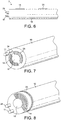
- FIG. 6 shows an alternative embodiment of instrument, in which the first tissue treatment electrode 11 and the first return electrode 24 are located on the distal end face of the instrument, while the second tissue treatment electrode 14 and the second return electrode 25 are located on the side of the shaft 10.
- the electrodes 11 and 24 are designed for tissue vaporisation, being relatively pointed in shape and sited quite close to each other.
- the electrodes 14 and 25 are designed for tissue coagulation, being relatively flat in shape, of a larger surface area than the electrodes 11 and 24, and sited at a greater distance one from the other.
- the choice of the electrode pairs 11 and 24 or 14 and 25 is made as previously described, using the footswitch unit 5, the push buttons 9 on the generator 1, or the handswitch buttons (not shown) on the instrument 3.
- This instrument is intended to be used such that tissue vaporisation is carried out as an end-effect instrument (by the electrodes 11 and 24), while tissue coagulation is carried out as a side-effect instrument (using the electrodes 14 and 25).
- an RF cutting signal or RF coagulation signal can be supplied to either electrode pair. This means that the end-effect electrodes 11 and 24 can be used for precise tissue treatment (either vaporisation or coagulation), while the side-effect electrodes 14 and 25 can be used for bulk tissue treatment (either vaporisation or coagulation).
- FIG. 7 shows an alternative embodiment in which all four electrodes 11, 24, 14 and 25 are located on the end face of the instrument 3.
- the electrodes 11 and 24 present a smaller surface area to the tissue to be treated as compared with the electrodes 14 and 25.
- the electrodes 14 and 25 are substantially planar, and are sited either side of the suction aperture 19 in communication with the suction tube 23.
- the switching circuit 62 directs either an RF cutting signal or an RF coagulation signal to whichever pair of electrodes is selected for use.
- the electrodes 11 and 24 are used for tissue vaporisation, while the electrodes 14 and 25 are used for tissue coagulation.
- the electrodes 11 and 24 are used for fine tissue treatment, while the electrodes 14 and 25 are used for bulk tissue treatment.
- the proximity of the electrodes 14 and 25 to the suction aperture 19 permits tissue to be evacuated efficiently during bulk tissue removal.
- Figure 8 shows a further embodiment, in which the electrodes 11, 24 and 14 are located on the end face of the instrument, while the second return electrode 25 is located on the side of the shaft 10.
- the characteristics of the electrode pair 11 and 24 are different from the electrode pair 14 and 25, allowing for different intended uses as previously described.
- the electrosurgical instrument can also be used for delivering a blended power output. This is achieved by automatically alternating the output of the RF generator 1 between the coagulation and vaporisation power levels, so that more haemostasis is produced then is possible in the vaporisation mode. As a consequence, the speed of tissue debulking is reduced, but the increased haemostasis is useful when cutting or debulking vascular tissue structures.
- the blended power output described above is delivered to one selected electrode pair
- the blended power output can alternatively be delivered to different electrode pairs, as described in our earlier US patent US 6,966,907 .
- a blend of RF vaporisation and coagulation voltages is provided by the generator, with the RF cutting voltage being supplied to one pair of electrodes (typically the electrodes 11 and 24) and the RF coagulation voltage being supplied to the other pair of electrodes (typically the electrodes 14 and 25).
- the RF cutting voltage being supplied to one pair of electrodes (typically the electrodes 11 and 24)
- the RF coagulation voltage being supplied to the other pair of electrodes (typically the electrodes 14 and 25).
- the output of the RF generator 1 can be pulsed at the vaporisation power level, without cycled activation of the coagulation mode. This produces a less aggressive tissue vaporisation than occurs in the vaporisation mode, with a consequent reduction in both bubble formation and the risk of tissue charring.
- an option is provided for both electrode pairs 11 and 24 and 14 and 25 to be simultaneously activated, for example so that the instrument 3 can deliver tissue treatment from both electrode pairs at the same time. It will be appreciated that some of these arrangements may require more sophisticated switching circuits than those described with reference to Figures 5A and 5B , but that these can be provided by those skilled in the art without undue difficulty.
Landscapes
- Health & Medical Sciences (AREA)
- Surgery (AREA)
- Engineering & Computer Science (AREA)
- Life Sciences & Earth Sciences (AREA)
- Heart & Thoracic Surgery (AREA)
- Animal Behavior & Ethology (AREA)
- Nuclear Medicine, Radiotherapy & Molecular Imaging (AREA)
- Otolaryngology (AREA)
- Veterinary Medicine (AREA)
- Public Health (AREA)
- Physics & Mathematics (AREA)
- Biomedical Technology (AREA)
- Medical Informatics (AREA)
- Molecular Biology (AREA)
- Plasma & Fusion (AREA)
- General Health & Medical Sciences (AREA)
- Neurosurgery (AREA)
- Neurology (AREA)
- Surgical Instruments (AREA)
Description
- This invention relates to an electrosurgical system for the treatment of tissue. Such systems are commonly used for the vaporisation and/or coagulation of tissue in surgical intervention, most commonly in "keyhole" or minimally invasive surgery, but also in "open" surgery.
- It is often the case that, during a surgical procedure, the surgeon is required to remove a first instrument and insert a second instrument, in order to achieve a particular tissue effect.
US2003045870 ,US2010010485 andEP0509670 disclose electrosurgical instruments with different electrode pairs at their distal end to achieve a particular effect when used. The present invention attempts to provide an electrosurgical system having a surgical instrument that can be used in more than one manner, so as to reduce the number of times that an alternative instrument needs to be used. The electrosurgical system of the invention is disclosed inindependent claim 1; preferred embodiments are disclosed in the dependent claims. - Accordingly, an electrosurgical system is provided for the treatment of tissue, the system comprising a generator for generating radio frequency power, and an electrosurgical instrument, the generator comprising;
- (i) a radio frequency output stage having at least a pair of radio frequency output lines,
- (ii) a power supply coupled to the output stage for supplying power to the output stage, the power being sufficient to effect the electrosurgical vaporisation of tissue; and
- (iii) a controller capable of varying a radio frequency signal supplied to the radio frequency output lines;
- By providing first and second bipolar electrode pairs, each pair having its own individual characteristic, the electrode pairs can be optimised for performing different functions, as opposed to having only one bipolar electrode pair that needs to perform all functions. Where prior art electrosurgical systems are provided with more than one active (tissue treatment) electrode, they normally still have to share a common return electrode. In the present invention, there is provided four electrodes, two active electrodes and two return electrodes, forming first and second discrete electrode pairs, both optimised for their particular function. Prior art systems known to the applicant involving multiple electrode pairs are generally instruments only capable of generating lesions. In contrast, the present invention is capable of the vaporisation of tissue, from at least one of the bipolar electrode pairs, and preferably both pairs.
- According to one convenient arrangement, the first and second bipolar electrode pairs are such that the first bipolar electrode pair is adapted to perform the vaporisation of tissue adjacent thereto, and the second bipolar electrode pair is adapted to perform the coagulation of tissue adjacent thereto. Thus one bipolar electrode pair is optimised for tissue vaporisation, while the other bipolar electrode pair is optimised for tissue coagulation. Conveniently, the exposed surface area of the first tissue treatment electrode is less than the exposed surface area of the second tissue treatment electrode. This helps to make the first electrode pair efficient for tissue vaporisation, and the second electrode pair efficient for tissue coagulation. Additionally or alternatively, the spacing between the first tissue treatment electrode and the first return electrode is less than the spacing between the second tissue treatment electrode and the second return electrode. This likewise helps to make the first electrode pair efficient for tissue vaporisation, and the second electrode pair efficient for tissue coagulation.
- According to an alternative arrangement, the first and second tissue treatment electrodes are such that they each have an exposed surface for treating tissue, the exposed surface of the first tissue treatment electrode being such as to treat tissue disposed on the longitudinal axis of the shaft, and the exposed surface of the second tissue treatment electrode being such as to treat tissue disposed laterally of the longitudinal axis of the shaft. This optimises one pair for treating tissue disposed on the longitudinal axis (an "end-effect instrument"), and the other pair for treating tissue laterally of said longitudinal axis (a "side-effect instrument").
- Conveniently, the first tissue treatment electrode protrudes through an aperture in the end of the shaft, while the second tissue treatment electrode conveniently protrudes through an aperture in the side of the shaft. By providing both an end-effect instrument and a side-effect instrument in one device, the present invention allows a surgeon to perform different surgical actions with the same instrument, as opposed to withdrawing a first instrument and inserting a second. By using the first tissue treatment electrode, the surgeon has an end-effect instrument, while using the second tissue treatment electrode provides the surgeon with a side-effect instrument. The surgeon can switch between these two modes of operation without needing to withdraw the instrument from the surgical site.
- According to a further alternative arrangement, the first and second bipolar electrode pairs are such that the first bipolar electrode pair is adapted to perform the fine treatment of tissue adjacent thereto, and the second bipolar electrode pair is adapted to perform the bulk treatment of tissue adjacent thereto. This provides one electrode pair for fine dissection and coagulation work, and an alternative electrode pair for bulk tissue removal or bulk coagulation, again with the same instrument and without the surgeon needing to withdraw a first instrument and insert a second. Conveniently, the exposed surface area of the first tissue treatment electrode is less than the exposed surface area of the second tissue treatment electrode. Additionally or alternatively, the spacing between the first tissue treatment electrode and the first return electrode is less than the spacing between the second tissue treatment electrode and the second return electrode. These features make one electrode pair suitable for fine tissue work, and the other suitable for bulk tissue treatment.
- The electrosurgical instrument is preferably provided with a suction lumen extending along the length of the shaft. In this way, the instrument can be used to aspirate tissue and other debris away from the surgical site. Conveniently, the first tissue treatment electrode is provided with at least one aperture in communication with the suction lumen. Similarly, the second tissue treatment electrode is conveniently provided with at least one aperture in communication with the suction lumen.
- The electrosurgical system includes the switch means by which the surgeon can select either the first or second bipolar electrode pairs. Conveniently, the switch means comprises a footswitch, although as an alternative the switch means conceivably comprises a handswitch carried on the electrosurgical instrument. Alternatively, the switch means can be located on the generator. The switch means activates the switching circuit, which is conveniently a part of the generator, although as an alternative the switching circuit is conceivably a part of the electrosurgical instrument.
- In a first arrangement, the generator and electrosurgical instrument are such that the instrument is operable in a conductive fluid, with the conductive fluid completing the current path between the tissue treatment electrodes and the one or more return electrodes. This means that the system operates to perform what is known as "underwater" electrosurgery, in which the conductive site is immersed in a conductive fluid such as saline, and the electrodes operate immersed in said conductive fluid. An example of this type of electrosurgical system is given in our earlier
US patent US 6,004,319 . The power and voltage setting used by the generator are such that the conductive fluid surrounding the tissue treatment electrodes is vaporised when the electrosurgical instrument is operated in its cutting mode. - Alternatively, the generator and electrosurgical instrument are such that the instrument is operatable in a dry-field environment, with the tissue treatment electrodes and the one or more return electrodes being in direct contact with the tissue to be treated, and with the tissue completing the current path therebetween. An example of this type of electrosurgical system is given in our earlier US patent
US 6,832,998 . The power and voltage settings used by the generator are generally lower than in underwater electrosurgical systems, as the electrodes contact the tissue directly and there is no need to form a pocket of vaporised saline surrounding the electrode. - The invention will now be further described, by way of example only, with reference to the drawings, in which:
-
Figure 1 is a schematic diagram of an electrosurgical system constructed in accordance with the present invention, -
Figure 2 is a perspective view of an electrosurgical instrument constructed in accordance with the present invention, and capable of being used in the system ofFigure 1 , -
Figure 3 is a plan view of the electrosurgical instrument ofFigure 2 , -
Figure 4 is a cross-section of the electrosurgical instrument ofFigure 3 , taken on the line A-A, -
Figures 5A and 5B are schematic block diagrams of the output stage of the electrosurgical generator ofFigure 1 , shown in different stages of operation, -
Figure 6 is a schematic side view of an alternative embodiment of electrosurgical instrument constructed in accordance with the present invention, and capable of being used in the system ofFigure 1 , -
Figure 7 is a schematic perspective view of a further alternative embodiment of electrosurgical instrument constructed in accordance with the present invention, and capable of being used in the system ofFigure 1 , and -
Figure 8 is a schematic perspective view of a further alternative embodiment of electrosurgical instrument constructed in accordance with the present invention, and capable of being used in the system ofFigure 1 . - Referring to the drawings,
Figure 1 shows electrosurgical apparatus including agenerator 1 having an output socket 2 providing a radio frequency (RF) output, via a connection cord 4, for an instrument in the form of ahandpiece 3. Activation of thegenerator 1 may be performed from thehandpiece 3 via a control connection (not shown) in the cord 4, or by means of afootswitch unit 5 connected separately to the rear of thegenerator 1 by afootswitch connection cord 6. In the illustrated embodiment, thefootswitch unit 5 has twofootswitches generator 1 respectively. The generator front panel haspush buttons display 8.Push buttons 9 are provided as an alternative means for selection between the desiccation and vaporisation modes, or between the different tissue treatment electrodes as will be described subsequently. - The
handpiece 3 comprises ashaft 10 with tissue treatment electrodes at its distal end, as will be described below.Figures 2 to 4 show a firsttissue treatment electrode 11 surrounded by aceramic insulator 12 projecting through an aperture in the end of theshaft 10. A secondtissue treatment electrode 14, surrounded by a secondceramic insulator 15, projects through a lateral aperture in the side of theshaft 10. Bothtissue treatment electrodes tissue treatment electrode 11 is provided with asuction aperture 17, and hasprojections 18 at each of its corners. Similarly, thetissue treatment electrode 14 is provided with asuction aperture 19, and hasprojections 20 at each of its corners. Theprojections tissue treatment electrodes projections tissue treatment electrodes electrodes - The
tissue treatment electrode 14 is located within theshaft 10 of theinstrument 3 by means of a shapedkeel portion 21, as described inUS 2009/0048592 . In summary, to assemble the instrument, thetissue treatment electrode 14 is lowered into achamber 22 provided within theceramic insulator 15. Asuction tube 23 is then pushed forwards to locate over thekeel portion 21 of theelectrode 14 and secure it in place. Both theaperture 17 in the firsttissue treatment electrode 11 and theaperture 19 in the secondtissue treatment electrode 14 are in communication with thesuction tube 23. In order to reduce the problems of vapour bubble production, and to assist with the removal of particulate material (such as tissue debris) from the region surrounding thetissue treatment electrodes suction tube 23 is connected to a suction pump (not shown) which can remove vapour bubbles via theshaft 10 of theinstrument 3 through theapertures suction tube 23 is made of an electrically-conductive material such as stainless steel or gold-plated copper, and can also constitute means for electrically connecting one of the tissue treatment electrodes (typically the second tissue treatment electrode 14) to thegenerator 1. - A
metallic ring 24 constitutes a first return electrode (associated with the first tissue treatment electrode 11). Thering 24 is located on the underside of theshaft 10, opposite theelectrode 14. A second return electrode 25 (associated with the second tissue treatment electrode 14) is provided by the distal end portion of theshaft 10, and a polytetrafluorethylene, a polyolefin, a polyester orethylene tetrafluoroethylene sleeve 26 surrounds the proximal portion of theshaft 10 adjacent to thereturn electrode 25. - The
RF generator 1 delivers an electrosurgical current to theinstrument 3. Thegenerator 1 includes means for varying the delivered output power to suit different electrosurgical requirements, such as vaporisation or coagulation. Thegenerator 1 is typically as described in our earlierUS patent US 6,293,942 , with a switching circuit 62 (SeeFigures 5A and 5B ) for switching the output lines from the generator to theelectrosurgical instrument 3. - The switching
circuit 62 comprisesconnections generator 1, andoutput connections output connection 62A is connected to the firsttissue treatment electrode 11, while theoutput connection 62C is connected to thefirst return electrode 24. Similarly, theoutput connection 62B is connected to the secondtissue treatment electrode 14, while theoutput connection 62D is connected to thesecond return electrode 25. The operation of the electrosurgical system will now be described. - When the user of the system wishes to use the
instrument 3 as an end-effect instrument, the user sends signals (via thefootswitch unit 5, the handswitches on theinstrument 3, or via thepush buttons 9 on the generator 1) to set the switchingcircuit 62 into the condition shown inFigure 5A . In this condition, theconnections generator 1 are connected to theoutput connections tissue treatment electrode 11 andfirst return electrode 24 respectively. RF power from thegenerator 1 is supplied to theelectrodes shaft 10. - Alternatively, when the user of the system wishes to use the
instrument 3 as a side-effect instrument, the user sends signals to set the switchingcircuit 62 into the condition shown inFigure 5B . In this condition, theconnections generator 1 are connected to theoutput connections tissue treatment electrode 14 and thesecond return electrode 25 respectively. RF power from thegenerator 1 is supplied to theelectrodes shaft 10. In this way, the surgeon can change between using theinstrument 3 as either an end-effect instrument or as a side-effect instrument, merely by operating thefootswitch 5, and without withdrawing theinstrument 3 from the surgical site. The versatility provided by this arrangement allows for a single instrument effectively to perform the function of two instruments, as desired. -
Figure 6 shows an alternative embodiment of instrument, in which the firsttissue treatment electrode 11 and thefirst return electrode 24 are located on the distal end face of the instrument, while the secondtissue treatment electrode 14 and thesecond return electrode 25 are located on the side of theshaft 10. Theelectrodes electrodes electrodes footswitch unit 5, thepush buttons 9 on thegenerator 1, or the handswitch buttons (not shown) on theinstrument 3. These activate the switchingcircuit 62 to direct the output from thegenerator 1 to one or other of the bipolar electrode pairs 11 and 24 or 14 and 25. This instrument is intended to be used such that tissue vaporisation is carried out as an end-effect instrument (by theelectrodes 11 and 24), while tissue coagulation is carried out as a side-effect instrument (using theelectrodes 14 and 25). However, an RF cutting signal or RF coagulation signal can be supplied to either electrode pair. This means that the end-effect electrodes effect electrodes -
Figure 7 shows an alternative embodiment in which all fourelectrodes instrument 3. As before, theelectrodes electrodes electrodes suction aperture 19 in communication with thesuction tube 23. As before, the switchingcircuit 62 directs either an RF cutting signal or an RF coagulation signal to whichever pair of electrodes is selected for use. In one method of operation, theelectrodes electrodes electrodes electrodes electrodes suction aperture 19 permits tissue to be evacuated efficiently during bulk tissue removal. - Finally,
Figure 8 shows a further embodiment, in which theelectrodes second return electrode 25 is located on the side of theshaft 10. As before, the characteristics of theelectrode pair electrode pair - Alternative embodiments will be envisaged by those skilled in the art without departing from the scope of the present invention. For example, the electrosurgical instrument can also be used for delivering a blended power output. This is achieved by automatically alternating the output of the
RF generator 1 between the coagulation and vaporisation power levels, so that more haemostasis is produced then is possible in the vaporisation mode. As a consequence, the speed of tissue debulking is reduced, but the increased haemostasis is useful when cutting or debulking vascular tissue structures. - Whereas the blended power output described above is delivered to one selected electrode pair, the blended power output can alternatively be delivered to different electrode pairs, as described in our earlier US patent
US 6,966,907 . In this arrangement, a blend of RF vaporisation and coagulation voltages is provided by the generator, with the RF cutting voltage being supplied to one pair of electrodes (typically theelectrodes 11 and 24) and the RF coagulation voltage being supplied to the other pair of electrodes (typically theelectrodes 14 and 25). In this way, simultaneous tissue cutting and coagulation is made possible, using bipolar electrode pairs designed specifically for each tissue effect. - Alternatively, the output of the
RF generator 1 can be pulsed at the vaporisation power level, without cycled activation of the coagulation mode. This produces a less aggressive tissue vaporisation than occurs in the vaporisation mode, with a consequent reduction in both bubble formation and the risk of tissue charring. In a further alternative arrangement, an option is provided for both electrode pairs 11 and 24 and 14 and 25 to be simultaneously activated, for example so that theinstrument 3 can deliver tissue treatment from both electrode pairs at the same time. It will be appreciated that some of these arrangements may require more sophisticated switching circuits than those described with reference toFigures 5A and 5B , but that these can be provided by those skilled in the art without undue difficulty.
an instrument shaft, and an electrode assembly at one end of the shaft, the electrode assembly comprising a first bipolar electrode pair comprising a first tissue treatment electrode and a first return electrode electrically insulated therefrom by means of a first insulation member, and a second bipolar electrode pair comprising a second tissue treatment electrode and a second return electrode electrically insulated therefrom by means of a second insulation member, the first and second bipolar electrode pairs each having a different characteristic;
the system further including a switch means and a switching circuit operable in response to the switch means to vary the connections between the radio frequency output lines and the first and second tissue treatment electrodes such that, in a first configuration, the first tissue treatment electrode is placed in circuit with the first return electrode so as to treat tissue adjacent to the first electrode pair, and, in a second configuration, the second tissue treatment electrode is placed in circuit with the second return electrode so as to treat tissue adjacent to the second electrode pair, the system being such that at least the first tissue treatment electrode is capable of the vaporisation of tissue.
Claims (14)
- An electrosurgical system comprising a generator for generating radio frequency power, and an electrosurgical instrument, the generator comprising;(i) a radio frequency output stage having at least a pair of radio frequency output lines,(ii) a power supply coupled to the output stage for supplying power to the output stage, the power being sufficient to effect the electrosurgical vaporisation of tissue; and(iii) a controller capable of varying a radio frequency signal supplied to the radio frequency output lines;the electrosurgical instrument comprising;
an instrument shaft having a longitudinal axis and a distal end face, and an electrode assembly fixedly attached to one end of the shaft, the electrode assembly comprising a first bipolar electrode pair comprising a first tissue treatment electrode and a first return electrode electrically insulated therefrom by means of a first insulation member, and a second bipolar electrode pair comprising a second tissue treatment electrode and a second return electrode electrically insulated therefrom by means of a second insulation member, the first and second tissue treatment electrodes each having an exposed surface for treating tissue, the exposed surface of the first tissue treatment electrode being disposed on the end face of the shaft such as to be capable of treating tissue disposed on the longitudinal axis of the shaft, and the exposed surface of the second tissue treatment electrode being disposed on the shaft such as to be capable of treating tissue disposed laterally of the longitudinal axis of the shaft the first return electrode being located on the shaft such that it is diametrically opposite the second tissue treatment electrode;
the system further including a switch means and a switching circuit operable in response to the switch means to vary the connections between the radio frequency output lines and the first and second tissue treatment electrodes such that, in a first configuration, the first tissue treatment electrode is placed in circuit with the first return electrode and not the second return electrode so as to treat tissue adjacent to the first electrode pair longitudinally of the shaft, and, in a second configuration, the second tissue treatment electrode is placed in circuit with the second return electrode so as to treat tissue adjacent to the second electrode pair laterally of the shaft, the system being such that at least the first tissue treatment electrode is capable of the vaporisation of tissue. - An electrosurgical system according to claim 1, wherein the first and second bipolar electrode pairs are such that the first bipolar electrode pair is adapted to perform the vaporisation of tissue adjacent thereto, and the second bipolar electrode pair is adapted to perform the coagulation of tissue adjacent thereto.
- An electrosurgical system according to claim 2, wherein the exposed surface area of the first tissue treatment electrode is less than the exposed surface area of the second tissue treatment electrode.
- An electrosurgical system according to claim 2 or claim 3, wherein the spacing between the first tissue treatment electrode and the first return electrode is less than the spacing between the second tissue treatment electrode and the second return electrode.
- An electrosurgical system according to any of the preceding claims, wherein the first tissue treatment electrode protrudes through an aperture in the end of the shaft.
- An electrosurgical system according to any of the preceding claims, wherein the second tissue treatment electrode protrudes through an aperture in the side of the shaft.
- An electrosurgical system according to claim 1, wherein the first and second bipolar electrode pairs are such that the first bipolar electrode pair is adapted to perform the fine treatment of tissue adjacent thereto, and the second bipolar electrode pair is adapted to perform the bulk treatment of tissue adjacent thereto; and
wherein the exposed surface area of the first tissue treatment electrode is less than the exposed surface area of the second tissue treatment electrode. - An electrosurgical system according to claim 7, wherein the spacing between the first tissue treatment electrode and the first return electrode is less than the spacing between the second tissue treatment electrode and the second return electrode.
- An electrosurgical system according to any preceding claim, including a suction lumen extending along the length of the shaft.
- An electrosurgical system according to claim 9, wherein the first tissue treatment electrode is provided with at least one aperture in communication with the suction lumen.
- An electrosurgical system according to claim 9 or claim 10, wherein the second tissue treatment electrode is provided with at least one aperture in communication with the suction lumen.
- An electrosurgical system according to any preceding claim, wherein the switching circuit is a part of the generator or a part of the electrosurgical instrument.
- An electrosurgical system according to any preceding claim, wherein the generator and the electrosurgical instrument are such that the instrument is operable in a conductive fluid, with the conductive fluid completing the current path between the tissue treatment electrodes and the return electrodes.
- An electrosurgical system according to any of claims 1 to 12, wherein the generator and electrosurgical instrument are such that the instrument is designed to be operated in a dry-field environment, with the tissue treatment electrodes and the return electrodes being in direct contact with the tissue to be treated, and with the tissue completing the current path therebetween.
Applications Claiming Priority (3)
| Application Number | Priority Date | Filing Date | Title |
|---|---|---|---|
| US28237910P | 2010-02-01 | 2010-02-01 | |
| GB1001640.0A GB2477350B (en) | 2010-02-01 | 2010-02-01 | Electrosurgical system |
| PCT/GB2011/000069 WO2011092453A1 (en) | 2010-02-01 | 2011-01-21 | Electrosurgical system |
Publications (2)
| Publication Number | Publication Date |
|---|---|
| EP2531129A1 EP2531129A1 (en) | 2012-12-12 |
| EP2531129B1 true EP2531129B1 (en) | 2019-06-19 |
Family
ID=42084306
Family Applications (1)
| Application Number | Title | Priority Date | Filing Date |
|---|---|---|---|
| EP11701538.8A Active EP2531129B1 (en) | 2010-02-01 | 2011-01-21 | Electrosurgical system |
Country Status (7)
| Country | Link |
|---|---|
| US (1) | US9700371B2 (en) |
| EP (1) | EP2531129B1 (en) |
| JP (2) | JP2013517878A (en) |
| AU (1) | AU2011209570B2 (en) |
| CA (1) | CA2788407C (en) |
| GB (1) | GB2477350B (en) |
| WO (1) | WO2011092453A1 (en) |
Families Citing this family (8)
| Publication number | Priority date | Publication date | Assignee | Title |
|---|---|---|---|---|
| US9364277B2 (en) | 2012-12-13 | 2016-06-14 | Cook Medical Technologies Llc | RF energy controller and method for electrosurgical medical devices |
| US9204921B2 (en) | 2012-12-13 | 2015-12-08 | Cook Medical Technologies Llc | RF energy controller and method for electrosurgical medical devices |
| DE102015119694A1 (en) * | 2015-11-13 | 2017-05-18 | Olympus Winter & Ibe Gmbh | Electrosurgical system for the resection of body tissue |
| KR101963621B1 (en) * | 2016-11-04 | 2019-04-01 | 주식회사 스타메드 | Radiofrequency ablation device |
| US11457978B2 (en) | 2018-06-18 | 2022-10-04 | Stryker Corporation | Radiofrequency probe and methods of use and manufacture of same |
| GB2590929B (en) * | 2020-01-07 | 2024-01-10 | Gyrus Medical Ltd | Surgical shaving instruments |
| GB2612370B (en) * | 2021-11-01 | 2023-10-25 | Gyrus Medical Ltd | Electrosurgical instrument |
| CN117731386B (en) * | 2024-02-08 | 2024-06-11 | 诺美伊创医疗科技(成都)有限公司 | Inner cutter head assembly, inner cutter assembly and plane cutter |
Citations (2)
| Publication number | Priority date | Publication date | Assignee | Title |
|---|---|---|---|---|
| EP0509670A2 (en) * | 1991-04-15 | 1992-10-21 | Everest Medical Corporation | Bipolar electrosurgical scalpel with paired loop electrodes |
| US20030045870A1 (en) * | 2001-09-06 | 2003-03-06 | Madsen Joseph R. | Direction-oriented and spatially controlled bipolar coagulator for in-situ cauterization of adherent cranial tissue occluding a ventricular catheter previously implanted in-vivo |
Family Cites Families (22)
| Publication number | Priority date | Publication date | Assignee | Title |
|---|---|---|---|---|
| US4438766A (en) * | 1981-09-03 | 1984-03-27 | C. R. Bard, Inc. | Electrosurgical generator |
| US5312401A (en) * | 1991-07-10 | 1994-05-17 | Electroscope, Inc. | Electrosurgical apparatus for laparoscopic and like procedures |
| US5697909A (en) * | 1992-01-07 | 1997-12-16 | Arthrocare Corporation | Methods and apparatus for surgical cutting |
| US6749604B1 (en) * | 1993-05-10 | 2004-06-15 | Arthrocare Corporation | Electrosurgical instrument with axially-spaced electrodes |
| US6117109A (en) * | 1995-11-22 | 2000-09-12 | Arthrocare Corporation | Systems and methods for electrosurgical incisions on external skin surfaces |
| US5558673A (en) * | 1994-09-30 | 1996-09-24 | Vidamed, Inc. | Medical probe device and method having a flexible resilient tape stylet |
| US6837887B2 (en) * | 1995-06-07 | 2005-01-04 | Arthrocare Corporation | Articulated electrosurgical probe and methods |
| US6293942B1 (en) | 1995-06-23 | 2001-09-25 | Gyrus Medical Limited | Electrosurgical generator method |
| DE69609473T3 (en) | 1995-06-23 | 2006-09-28 | Gyrus Medical Ltd., St. Mellons | ELECTRO-SURGICAL INSTRUMENT |
| GB9612993D0 (en) * | 1996-06-20 | 1996-08-21 | Gyrus Medical Ltd | Electrosurgical instrument |
| US7104986B2 (en) * | 1996-07-16 | 2006-09-12 | Arthrocare Corporation | Intervertebral disc replacement method |
| US6152923A (en) * | 1999-04-28 | 2000-11-28 | Sherwood Services Ag | Multi-contact forceps and method of sealing, coagulating, cauterizing and/or cutting vessels and tissue |
| AU5142900A (en) * | 1999-05-21 | 2000-12-12 | Arthrocare Corporation | Systems and methods for electrosurgical treatment of intervertebral discs |
| US6966907B2 (en) | 2001-08-27 | 2005-11-22 | Gyrus Medical Limited | Electrosurgical generator and system |
| US6808525B2 (en) * | 2001-08-27 | 2004-10-26 | Gyrus Medical, Inc. | Bipolar electrosurgical hook probe for cutting and coagulating tissue |
| GB0130975D0 (en) | 2001-12-27 | 2002-02-13 | Gyrus Group Plc | A surgical instrument |
| US7553309B2 (en) * | 2004-10-08 | 2009-06-30 | Covidien Ag | Electrosurgical system employing multiple electrodes and method thereof |
| US20080249523A1 (en) * | 2007-04-03 | 2008-10-09 | Tyco Healthcare Group Lp | Controller for flexible tissue ablation procedures |
| GB2451623A (en) | 2007-08-03 | 2009-02-11 | Gyrus Medical Ltd | Electrosurgical Instrument for underwater surgery with aspiration aperture in electrode |
| DE102007062939B4 (en) * | 2007-12-28 | 2014-03-20 | Sutter Medizintechnik Gmbh | Cutting and u. coagulation |
| US8361065B2 (en) * | 2008-07-10 | 2013-01-29 | HS West Investements, LLC | Electrosurgical instrument with an ablation mode and a coagulation mode |
| US20100152726A1 (en) * | 2008-12-16 | 2010-06-17 | Arthrocare Corporation | Electrosurgical system with selective control of active and return electrodes |
-
2010
- 2010-02-01 GB GB1001640.0A patent/GB2477350B/en active Active
-
2011
- 2011-01-21 WO PCT/GB2011/000069 patent/WO2011092453A1/en not_active Ceased
- 2011-01-21 EP EP11701538.8A patent/EP2531129B1/en active Active
- 2011-01-21 JP JP2012550504A patent/JP2013517878A/en active Pending
- 2011-01-21 AU AU2011209570A patent/AU2011209570B2/en active Active
- 2011-01-21 CA CA2788407A patent/CA2788407C/en active Active
- 2011-01-28 US US13/016,221 patent/US9700371B2/en active Active
-
2015
- 2015-10-01 JP JP2015195601A patent/JP6090809B2/en active Active
Patent Citations (2)
| Publication number | Priority date | Publication date | Assignee | Title |
|---|---|---|---|---|
| EP0509670A2 (en) * | 1991-04-15 | 1992-10-21 | Everest Medical Corporation | Bipolar electrosurgical scalpel with paired loop electrodes |
| US20030045870A1 (en) * | 2001-09-06 | 2003-03-06 | Madsen Joseph R. | Direction-oriented and spatially controlled bipolar coagulator for in-situ cauterization of adherent cranial tissue occluding a ventricular catheter previously implanted in-vivo |
Also Published As
| Publication number | Publication date |
|---|---|
| EP2531129A1 (en) | 2012-12-12 |
| US9700371B2 (en) | 2017-07-11 |
| CA2788407C (en) | 2018-04-17 |
| CA2788407A1 (en) | 2011-08-04 |
| AU2011209570B2 (en) | 2015-12-10 |
| WO2011092453A1 (en) | 2011-08-04 |
| AU2011209570A2 (en) | 2012-09-20 |
| GB2477350A (en) | 2011-08-03 |
| US20110202050A1 (en) | 2011-08-18 |
| GB201001640D0 (en) | 2010-03-17 |
| AU2011209570A1 (en) | 2012-09-20 |
| JP6090809B2 (en) | 2017-03-08 |
| JP2013517878A (en) | 2013-05-20 |
| GB2477350B (en) | 2015-09-09 |
| JP2016025947A (en) | 2016-02-12 |
Similar Documents
| Publication | Publication Date | Title |
|---|---|---|
| EP2531132B1 (en) | Electrosurgical instrument and system | |
| US8840610B2 (en) | Electrosurgical system including electrosurgical instrument for longitudinal and lateral treatment | |
| CA2788407C (en) | Electrosurgical system | |
| EP2531130B1 (en) | Electrosurgical instrument with two active electrodes optimised for vaporisation and coagulation | |
| US8361065B2 (en) | Electrosurgical instrument with an ablation mode and a coagulation mode | |
| CA2788396C (en) | Electrosurgical instrument | |
| AU2011209579A2 (en) | Electrosurgical instrument | |
| US8518034B2 (en) | Electrosurgical instrument and system | |
| US20240407834A1 (en) | Electrosurgical device with directional electrode |
Legal Events
| Date | Code | Title | Description |
|---|---|---|---|
| PUAI | Public reference made under article 153(3) epc to a published international application that has entered the european phase |
Free format text: ORIGINAL CODE: 0009012 |
|
| 17P | Request for examination filed |
Effective date: 20120821 |
|
| AK | Designated contracting states |
Kind code of ref document: A1 Designated state(s): AL AT BE BG CH CY CZ DE DK EE ES FI FR GB GR HR HU IE IS IT LI LT LU LV MC MK MT NL NO PL PT RO RS SE SI SK SM TR |
|
| DAX | Request for extension of the european patent (deleted) | ||
| STAA | Information on the status of an ep patent application or granted ep patent |
Free format text: STATUS: EXAMINATION IS IN PROGRESS |
|
| 17Q | First examination report despatched |
Effective date: 20180706 |
|
| GRAP | Despatch of communication of intention to grant a patent |
Free format text: ORIGINAL CODE: EPIDOSNIGR1 |
|
| STAA | Information on the status of an ep patent application or granted ep patent |
Free format text: STATUS: GRANT OF PATENT IS INTENDED |
|
| RIC1 | Information provided on ipc code assigned before grant |
Ipc: A61B 18/12 20060101ALI20190108BHEP Ipc: A61B 18/14 20060101AFI20190108BHEP Ipc: A61B 18/00 20060101ALI20190108BHEP |
|
| INTG | Intention to grant announced |
Effective date: 20190129 |
|
| GRAS | Grant fee paid |
Free format text: ORIGINAL CODE: EPIDOSNIGR3 |
|
| GRAA | (expected) grant |
Free format text: ORIGINAL CODE: 0009210 |
|
| STAA | Information on the status of an ep patent application or granted ep patent |
Free format text: STATUS: THE PATENT HAS BEEN GRANTED |
|
| AK | Designated contracting states |
Kind code of ref document: B1 Designated state(s): AL AT BE BG CH CY CZ DE DK EE ES FI FR GB GR HR HU IE IS IT LI LT LU LV MC MK MT NL NO PL PT RO RS SE SI SK SM TR |
|
| REG | Reference to a national code |
Ref country code: GB Ref legal event code: FG4D |
|
| REG | Reference to a national code |
Ref country code: CH Ref legal event code: EP |
|
| REG | Reference to a national code |
Ref country code: IE Ref legal event code: FG4D |
|
| REG | Reference to a national code |
Ref country code: DE Ref legal event code: R096 Ref document number: 602011059819 Country of ref document: DE |
|
| REG | Reference to a national code |
Ref country code: AT Ref legal event code: REF Ref document number: 1144509 Country of ref document: AT Kind code of ref document: T Effective date: 20190715 |
|
| REG | Reference to a national code |
Ref country code: NL Ref legal event code: MP Effective date: 20190619 |
|
| PG25 | Lapsed in a contracting state [announced via postgrant information from national office to epo] |
Ref country code: LT Free format text: LAPSE BECAUSE OF FAILURE TO SUBMIT A TRANSLATION OF THE DESCRIPTION OR TO PAY THE FEE WITHIN THE PRESCRIBED TIME-LIMIT Effective date: 20190619 Ref country code: FI Free format text: LAPSE BECAUSE OF FAILURE TO SUBMIT A TRANSLATION OF THE DESCRIPTION OR TO PAY THE FEE WITHIN THE PRESCRIBED TIME-LIMIT Effective date: 20190619 Ref country code: HR Free format text: LAPSE BECAUSE OF FAILURE TO SUBMIT A TRANSLATION OF THE DESCRIPTION OR TO PAY THE FEE WITHIN THE PRESCRIBED TIME-LIMIT Effective date: 20190619 Ref country code: AL Free format text: LAPSE BECAUSE OF FAILURE TO SUBMIT A TRANSLATION OF THE DESCRIPTION OR TO PAY THE FEE WITHIN THE PRESCRIBED TIME-LIMIT Effective date: 20190619 Ref country code: SE Free format text: LAPSE BECAUSE OF FAILURE TO SUBMIT A TRANSLATION OF THE DESCRIPTION OR TO PAY THE FEE WITHIN THE PRESCRIBED TIME-LIMIT Effective date: 20190619 Ref country code: NO Free format text: LAPSE BECAUSE OF FAILURE TO SUBMIT A TRANSLATION OF THE DESCRIPTION OR TO PAY THE FEE WITHIN THE PRESCRIBED TIME-LIMIT Effective date: 20190919 |
|
| REG | Reference to a national code |
Ref country code: LT Ref legal event code: MG4D |
|
| PG25 | Lapsed in a contracting state [announced via postgrant information from national office to epo] |
Ref country code: LV Free format text: LAPSE BECAUSE OF FAILURE TO SUBMIT A TRANSLATION OF THE DESCRIPTION OR TO PAY THE FEE WITHIN THE PRESCRIBED TIME-LIMIT Effective date: 20190619 Ref country code: GR Free format text: LAPSE BECAUSE OF FAILURE TO SUBMIT A TRANSLATION OF THE DESCRIPTION OR TO PAY THE FEE WITHIN THE PRESCRIBED TIME-LIMIT Effective date: 20190920 Ref country code: RS Free format text: LAPSE BECAUSE OF FAILURE TO SUBMIT A TRANSLATION OF THE DESCRIPTION OR TO PAY THE FEE WITHIN THE PRESCRIBED TIME-LIMIT Effective date: 20190619 Ref country code: BG Free format text: LAPSE BECAUSE OF FAILURE TO SUBMIT A TRANSLATION OF THE DESCRIPTION OR TO PAY THE FEE WITHIN THE PRESCRIBED TIME-LIMIT Effective date: 20190919 |
|
| REG | Reference to a national code |
Ref country code: AT Ref legal event code: MK05 Ref document number: 1144509 Country of ref document: AT Kind code of ref document: T Effective date: 20190619 |
|
| PG25 | Lapsed in a contracting state [announced via postgrant information from national office to epo] |
Ref country code: AT Free format text: LAPSE BECAUSE OF FAILURE TO SUBMIT A TRANSLATION OF THE DESCRIPTION OR TO PAY THE FEE WITHIN THE PRESCRIBED TIME-LIMIT Effective date: 20190619 Ref country code: NL Free format text: LAPSE BECAUSE OF FAILURE TO SUBMIT A TRANSLATION OF THE DESCRIPTION OR TO PAY THE FEE WITHIN THE PRESCRIBED TIME-LIMIT Effective date: 20190619 Ref country code: CZ Free format text: LAPSE BECAUSE OF FAILURE TO SUBMIT A TRANSLATION OF THE DESCRIPTION OR TO PAY THE FEE WITHIN THE PRESCRIBED TIME-LIMIT Effective date: 20190619 Ref country code: RO Free format text: LAPSE BECAUSE OF FAILURE TO SUBMIT A TRANSLATION OF THE DESCRIPTION OR TO PAY THE FEE WITHIN THE PRESCRIBED TIME-LIMIT Effective date: 20190619 Ref country code: SK Free format text: LAPSE BECAUSE OF FAILURE TO SUBMIT A TRANSLATION OF THE DESCRIPTION OR TO PAY THE FEE WITHIN THE PRESCRIBED TIME-LIMIT Effective date: 20190619 Ref country code: EE Free format text: LAPSE BECAUSE OF FAILURE TO SUBMIT A TRANSLATION OF THE DESCRIPTION OR TO PAY THE FEE WITHIN THE PRESCRIBED TIME-LIMIT Effective date: 20190619 Ref country code: PT Free format text: LAPSE BECAUSE OF FAILURE TO SUBMIT A TRANSLATION OF THE DESCRIPTION OR TO PAY THE FEE WITHIN THE PRESCRIBED TIME-LIMIT Effective date: 20191021 |
|
| PG25 | Lapsed in a contracting state [announced via postgrant information from national office to epo] |
Ref country code: ES Free format text: LAPSE BECAUSE OF FAILURE TO SUBMIT A TRANSLATION OF THE DESCRIPTION OR TO PAY THE FEE WITHIN THE PRESCRIBED TIME-LIMIT Effective date: 20190619 Ref country code: IS Free format text: LAPSE BECAUSE OF FAILURE TO SUBMIT A TRANSLATION OF THE DESCRIPTION OR TO PAY THE FEE WITHIN THE PRESCRIBED TIME-LIMIT Effective date: 20191019 Ref country code: SM Free format text: LAPSE BECAUSE OF FAILURE TO SUBMIT A TRANSLATION OF THE DESCRIPTION OR TO PAY THE FEE WITHIN THE PRESCRIBED TIME-LIMIT Effective date: 20190619 |
|
| PG25 | Lapsed in a contracting state [announced via postgrant information from national office to epo] |
Ref country code: TR Free format text: LAPSE BECAUSE OF FAILURE TO SUBMIT A TRANSLATION OF THE DESCRIPTION OR TO PAY THE FEE WITHIN THE PRESCRIBED TIME-LIMIT Effective date: 20190619 |
|
| PG25 | Lapsed in a contracting state [announced via postgrant information from national office to epo] |
Ref country code: DK Free format text: LAPSE BECAUSE OF FAILURE TO SUBMIT A TRANSLATION OF THE DESCRIPTION OR TO PAY THE FEE WITHIN THE PRESCRIBED TIME-LIMIT Effective date: 20190619 Ref country code: PL Free format text: LAPSE BECAUSE OF FAILURE TO SUBMIT A TRANSLATION OF THE DESCRIPTION OR TO PAY THE FEE WITHIN THE PRESCRIBED TIME-LIMIT Effective date: 20190619 |
|
| PG25 | Lapsed in a contracting state [announced via postgrant information from national office to epo] |
Ref country code: IS Free format text: LAPSE BECAUSE OF FAILURE TO SUBMIT A TRANSLATION OF THE DESCRIPTION OR TO PAY THE FEE WITHIN THE PRESCRIBED TIME-LIMIT Effective date: 20200224 |
|
| REG | Reference to a national code |
Ref country code: DE Ref legal event code: R097 Ref document number: 602011059819 Country of ref document: DE |
|
| PLBE | No opposition filed within time limit |
Free format text: ORIGINAL CODE: 0009261 |
|
| STAA | Information on the status of an ep patent application or granted ep patent |
Free format text: STATUS: NO OPPOSITION FILED WITHIN TIME LIMIT |
|
| PG2D | Information on lapse in contracting state deleted |
Ref country code: IS |
|
| 26N | No opposition filed |
Effective date: 20200603 |
|
| PG25 | Lapsed in a contracting state [announced via postgrant information from national office to epo] |
Ref country code: SI Free format text: LAPSE BECAUSE OF FAILURE TO SUBMIT A TRANSLATION OF THE DESCRIPTION OR TO PAY THE FEE WITHIN THE PRESCRIBED TIME-LIMIT Effective date: 20190619 Ref country code: MC Free format text: LAPSE BECAUSE OF FAILURE TO SUBMIT A TRANSLATION OF THE DESCRIPTION OR TO PAY THE FEE WITHIN THE PRESCRIBED TIME-LIMIT Effective date: 20190619 |
|
| REG | Reference to a national code |
Ref country code: CH Ref legal event code: PL |
|
| GBPC | Gb: european patent ceased through non-payment of renewal fee |
Effective date: 20200121 |
|
| REG | Reference to a national code |
Ref country code: BE Ref legal event code: MM Effective date: 20200131 |
|
| PG25 | Lapsed in a contracting state [announced via postgrant information from national office to epo] |
Ref country code: GB Free format text: LAPSE BECAUSE OF NON-PAYMENT OF DUE FEES Effective date: 20200121 Ref country code: LU Free format text: LAPSE BECAUSE OF NON-PAYMENT OF DUE FEES Effective date: 20200121 |
|
| PG25 | Lapsed in a contracting state [announced via postgrant information from national office to epo] |
Ref country code: LI Free format text: LAPSE BECAUSE OF NON-PAYMENT OF DUE FEES Effective date: 20200131 Ref country code: CH Free format text: LAPSE BECAUSE OF NON-PAYMENT OF DUE FEES Effective date: 20200131 Ref country code: BE Free format text: LAPSE BECAUSE OF NON-PAYMENT OF DUE FEES Effective date: 20200131 |
|
| PG25 | Lapsed in a contracting state [announced via postgrant information from national office to epo] |
Ref country code: IE Free format text: LAPSE BECAUSE OF NON-PAYMENT OF DUE FEES Effective date: 20200121 |
|
| PG25 | Lapsed in a contracting state [announced via postgrant information from national office to epo] |
Ref country code: MT Free format text: LAPSE BECAUSE OF FAILURE TO SUBMIT A TRANSLATION OF THE DESCRIPTION OR TO PAY THE FEE WITHIN THE PRESCRIBED TIME-LIMIT Effective date: 20190619 Ref country code: CY Free format text: LAPSE BECAUSE OF FAILURE TO SUBMIT A TRANSLATION OF THE DESCRIPTION OR TO PAY THE FEE WITHIN THE PRESCRIBED TIME-LIMIT Effective date: 20190619 |
|
| PG25 | Lapsed in a contracting state [announced via postgrant information from national office to epo] |
Ref country code: MK Free format text: LAPSE BECAUSE OF FAILURE TO SUBMIT A TRANSLATION OF THE DESCRIPTION OR TO PAY THE FEE WITHIN THE PRESCRIBED TIME-LIMIT Effective date: 20190619 |
|
| PGFP | Annual fee paid to national office [announced via postgrant information from national office to epo] |
Ref country code: DE Payment date: 20250121 Year of fee payment: 15 |
|
| PGFP | Annual fee paid to national office [announced via postgrant information from national office to epo] |
Ref country code: FR Payment date: 20250127 Year of fee payment: 15 |
|
| PGFP | Annual fee paid to national office [announced via postgrant information from national office to epo] |
Ref country code: IT Payment date: 20250122 Year of fee payment: 15 |