EP2530798A1 - Wire harness protector - Google Patents
Wire harness protector Download PDFInfo
- Publication number
- EP2530798A1 EP2530798A1 EP11855944A EP11855944A EP2530798A1 EP 2530798 A1 EP2530798 A1 EP 2530798A1 EP 11855944 A EP11855944 A EP 11855944A EP 11855944 A EP11855944 A EP 11855944A EP 2530798 A1 EP2530798 A1 EP 2530798A1
- Authority
- EP
- European Patent Office
- Prior art keywords
- main body
- convoluted conduit
- lid
- diameter
- protector
- Prior art date
- Legal status (The legal status is an assumption and is not a legal conclusion. Google has not performed a legal analysis and makes no representation as to the accuracy of the status listed.)
- Granted
Links
Images



Classifications
-
- B—PERFORMING OPERATIONS; TRANSPORTING
- B60—VEHICLES IN GENERAL
- B60R—VEHICLES, VEHICLE FITTINGS, OR VEHICLE PARTS, NOT OTHERWISE PROVIDED FOR
- B60R16/00—Electric or fluid circuits specially adapted for vehicles and not otherwise provided for; Arrangement of elements of electric or fluid circuits specially adapted for vehicles and not otherwise provided for
- B60R16/02—Electric or fluid circuits specially adapted for vehicles and not otherwise provided for; Arrangement of elements of electric or fluid circuits specially adapted for vehicles and not otherwise provided for electric constitutive elements
- B60R16/0207—Wire harnesses
- B60R16/0215—Protecting, fastening and routing means therefor
-
- H—ELECTRICITY
- H02—GENERATION; CONVERSION OR DISTRIBUTION OF ELECTRIC POWER
- H02G—INSTALLATION OF ELECTRIC CABLES OR LINES, OR OF COMBINED OPTICAL AND ELECTRIC CABLES OR LINES
- H02G3/00—Installations of electric cables or lines or protective tubing therefor in or on buildings, equivalent structures or vehicles
- H02G3/02—Details
- H02G3/04—Protective tubing or conduits, e.g. cable ladders or cable troughs
- H02G3/0462—Tubings, i.e. having a closed section
- H02G3/0487—Tubings, i.e. having a closed section with a non-circular cross-section
-
- H—ELECTRICITY
- H02—GENERATION; CONVERSION OR DISTRIBUTION OF ELECTRIC POWER
- H02G—INSTALLATION OF ELECTRIC CABLES OR LINES, OR OF COMBINED OPTICAL AND ELECTRIC CABLES OR LINES
- H02G3/00—Installations of electric cables or lines or protective tubing therefor in or on buildings, equivalent structures or vehicles
- H02G3/30—Installations of cables or lines on walls, floors or ceilings
Definitions
- the present invention relates to a wire harness protector. More specifically, the present invention enables a protector that positions and holds a front end of a convoluted conduit covering a wire harness to accommodate convoluted conduits having different outer diameters.
- a wire harness routed in a vehicle such as an automobile has an area in which a wiring path needs to be guided and the wire harness needs to be protected to prevent interference with outer members, and this area is inserted into a protector made of a molded resin. Further, at a portion of the wire harness not covered by the protector, the wire harness is inserted into a convoluted conduit having ring-shaped crests and troughs alternating in an axial direction such that the wire harness is bendably, extendably and contractably covered by the convoluted conduit.
- the wire harness covered by the convoluted conduit When the wire harness covered by the convoluted conduit is continuously covered by the protector, in a case where an area covered by the protector is short or no branch line is branched off from a portion covered by the protector, the wire harness may be inserted into the entire length of the protector without removing the convoluted conduit. Alternatively, in many cases, the front end of the convoluted conduit covering the wire harness is inserted into the protector, and the wire harness is inserted into the protector without the convoluted conduit.
- a plurality of circular arc-shaped ribs 115 are provided in an axial direction protruding from an inner circumferential surface on a front-end opening side of a main body 100 and a lid (not shown) of a protector, the ribs 115 fitting troughs 111 of a convoluted conduit 110.
- the total number of electric wires configuring a wire harness is different depending on a vehicle's destination or class. Accordingly, an outer diameter of the wire harness differs, and a diameter of the convoluted conduit 110 covering the wire harness also differs.
- an outer diameter of a trough of a convoluted conduit also differs.
- the ribs 115 provided to the protector are for a large-diameter convoluted conduit, the ribs 115 do not fit a diameter of a trough of a small-diameter convoluted conduit, and the convoluted conduit cannot be securely held. Therefore, it is necessary to provide a protector for each size of convoluted conduit, which results in an increase in the number of components and in manufacturing costs.
- a protector that can accommodate convoluted conduits having different sizes, large and small.
- a main body 101 of a protector 100 is used for both, a large-diameter lid 102A and a small-diameter lid 102B are provided as lids.
- Ribs 104 protruding from an internal surface of the main body 101 and engaging with troughs of a convoluted conduit are configured to fit a large-diameter convoluted conduit CT-L.
- Ribs provided to the large-diameter lid 102A are configured to fit the large-diameter convoluted conduit.
- Ribs provided to the small-diameter lid 102B are configured to fit a small-diameter convoluted conduit CT-S.
- Patent Literature 1 Japanese Patent Laid-Open Publication No. 2006-74844
- one main body 101 can be used for both, but a lid is needed for each size of convoluted conduit.
- two types of lid are needed.
- four types of lid are needed. Accordingly, only the main body can be used for all and a lid needs to be prepared for each size. Thus, it is desirable that a lid can be used as much as possible regardless of the size of a convoluted conduit.
- the present invention has been devised to address the above-described problem.
- Objects of the present invention are to use one protector lid as much as possible regardless of the size of a convoluted conduit to be covered and kept in a position, to reduce the number of components, and to reduce manufacturing costs accordingly.
- the present invention provides a protector that positions and holds on an insertion inlet side a convoluted conduit covering a wire harness and that includes a main body having a bottom wall and two side walls, and a lid provided separately from the main body and covering an upper surface opening of the main body.
- Locks capable of mutually connecting the main body and the lid are provided on both sides in a length direction of each of the main body and the lid, and the locks of the lid are provided in symmetrical positions to enable connection with the locks of the main body even when the lid is rotated by 180 degrees.
- a convoluted conduit engagement portion having ribs that fit troughs of a large-diameter convoluted conduit extends from the bottom wall on one end side in the length direction of the main body to internal surfaces of the two side walls.
- a large-diameter convoluted conduit engagement portion having ribs that fit the troughs of the large-diameter convoluted conduit is provided on an internal surface on one end side in the length direction of the lid, and a small-diameter convoluted conduit engagement portion having ribs that fit troughs of a small-diameter convoluted conduit is provided on an internal surface on the other end side.
- the convoluted conduit engagement portions on both the main body side and the lid side include a plurality of ribs having the same pitch and allow the lid to be rotated by 180 degrees to correspond to an outer diameter of an inserted convoluted conduit and to connect to the main body.
- the ribs for the large-diameter convoluted conduit protrude in a circular arc shape, the circular arc of the ribs having a larger outer diameter as well as a smaller rib protrusion amount.
- the circular arc of the ribs for the small-diameter convoluted conduit has a smaller outer diameter as well as a greater rib protrusion amount.
- a pitch for troughs and crests of convoluted conduits is generally the same regardless of an outer diameter thereof. Therefore, when a diameter and a height of ribs are different as described above, it is possible for the ribs to precisely fit different sizes of convoluted conduit, both large and small diameter convoluted conduits.
- the main body of the protector includes protruding ribs that fit the troughs of the large-diameter convoluted conduit.
- the lid includes the ribs for the large-diameter convoluted conduit protruding on one end side in the length direction and the ribs for the small-diameter convoluted conduit protruding on the other end side in the length direction.
- the ribs for a large-diameter convoluted conduit provided on the lid are positioned facing the side of the main body where the ribs for engagement with the convoluted conduit protrude. Accordingly, the ribs of the main body are inserted into a lower half circumference of the troughs at the end of the large-diameter convoluted conduit that is inserted from an opening at one end of the protector. Further, the ribs on the lid are inserted into an upper half circumference of the troughs of the large-diameter convoluted conduit.
- the large-diameter convoluted conduit is positioned and held inside the protector.
- the ribs for a small-diameter convoluted conduit provided on the lid are positioned facing the side at the main body where the ribs for engagement with the convoluted conduit protrude. Accordingly, the ribs of the main body are inserted into a central portion of the lower half circumference of the troughs at the end of the small-diameter convoluted conduit that is inserted from an opening at one end of the protector, while the ribs of the lid are precisely inserted into the upper half circumference of the toughs.
- the small-diameter convoluted conduit is positioned and held inside the protector. Therefore, when there are two different sizes, the lid can be used for both the sizes, and thus only one type of protector needs to be provided. In a case where there are four different sizes, only one main body and two types of lid are needed, which results in a great reduction in the number of components.
- the wire harness covered by the protector of the present invention is inserted through the convoluted conduit on one end side of the protector while the wire harness on the other end side is bound by a band clip without being inserted through the convoluted conduit.
- a recess for the band clip is provided to the bottom wall of the main body of the protector.
- a clip latching hole is provided in the center of the recess.
- the convoluted conduit covering the wire harness is a portion of several pitches from one end side of the protector, specifically the inlet.
- This portion of the convoluted conduit inserted into the protector is positioned and held by the ribs of the main body and of the lid.
- the wire harness inserted into the protector does not go through the convoluted conduit. Since a plurality of wires are separated from one another, they are bound by a band of the band clip wrapping around the wires. A latching clip integrally provided with the band is inserted and latched in the clip latching hole provided to the bottom wall of the main body of the protector.
- a dividing wall is provided in the length direction in the middle of a width direction of the main body.
- a wire harness insertion path is provided on one side divided by the dividing wall.
- the ribs are provided on the internal surface on one end side of the wire harness insertion path to define the convoluted conduit engagement portion.
- a splice housing is provided on the other side of the dividing wall.
- a width of the lid corresponds to a width of the main body.
- the large-diameter convoluted conduit engagement portion and the small-diameter convoluted conduit engagement portion may be diagonally positioned.
- a branch line having the splice is branched off before being inserted into the protector.
- the splice is housed in the splice housing provided in the protector. Accordingly, because the width of the main body is increased, the width of the lid that locks and connects to the main body is also increased.
- the ribs for the large-diameter convoluted conduit and the ribs for the small-diameter convoluted conduit are diagonally positioned. Thereby, the lid side ribs are placed in an upper surface position opposite to the ribs of the main body in a state where the lid is rotated by 180 degrees.
- a protector according to the present invention is provided with ribs that latch onto a large-diameter convoluted conduit on one side in a length direction of a lid provided separately from a main body, and ribs that latch onto a small-diameter convoluted conduit on the other side. Therefore, by merely rotating the lid by 180 degrees, it becomes possible even for one protector main body and one protector lid to accommodate convoluted conduits having two different diameters. Accordingly, since one protector can accommodate convoluted conduits having different sizes, it is possible to greatly reduce the number of components as well as manufacturing costs.
- Figs. 1 to 6 illustrate a first embodiment.
- a predetermined area of a wire harness 1 routed in an automobile is inserted through a protector 2 formed of molded resin.
- the wire harness 1 inserted into an inlet 2a which is an opening at one end side in a length direction of the protector 2, runs through a convoluted conduit 3 (a large-diameter convoluted conduit 3L or a small-diameter convoluted conduit 3S shown in Fig. 6 ).
- a front end 3a of the convoluted conduit 3 internally engages and latches onto the protector 2 on the inlet 2a side.
- the wire harness 1 is pulled out from the front end 3a of the convoluted conduit.
- the wire harness 1 is bound by a band clip 5 at a position between a central position in the length direction of the protector 2 and an outlet 2b, which is an opening on the other end side.
- the wire harness 1 is pulled out from the outlet 2b.
- the protector 2 is configured with a main body 10 and a lid 11.
- the main body 10 shown in Fig. 2(A) includes a bottom wall 12, two side walls 13A and 13B protruding from both ends in a width direction of the bottom wall 12, and a dividing wall 14 in the middle.
- a bracket 15 protrudes from an outer surface of the side wall 13B to be fixated to other members.
- the bracket 15 is provided with a latching clip 16 and a lock 17.
- a wire harness insertion path 18 is defined between the side wall 13A and the dividing wall 14. One end in the length direction of the wire harness insertion path 18 is the inlet 2a, and the other end is the outlet 2b.
- a splice housing 19 is defined between the dividing wall 14 and the side wall 13B. One end of the splice housing 19 is provided with a closed wall 19a, and the other end is an opening 19b for splice insertion.
- a width of the wire harness insertion path 18 is set to be wide, and at least twice a width of the splice housing 19.
- a convoluted conduit engagement portion 20 is provided on internal surfaces of the bottom wall 12, the side wall 13A, and the dividing wall 14.
- the convoluted conduit engagement portion 20 has four protruding U-shaped ribs 21 in an axis direction extending from an upper end of the side wall 13A to an upper end of the dividing wall 14.
- the ribs 21 are each in a circular arc shape having a diameter that precisely fits troughs 45 of the large-diameter convoluted conduit 3L and have a relatively low protrusion height.
- a pitch for crests and troughs of the convoluted conduit 3 is substantially the same regardless of a diameter of the convoluted conduit 3.
- the pitch for the troughs 45 and crests 46 of the large-diameter convoluted conduit 3L and the pitch for troughs 40 and crests 41 of the small-diameter convoluted conduit 3 S are the same.
- the pitch for the ribs 21 provided to the main body 10 is also the same, which is a fixed pitch P.
- a large, circular downward protrusion 22 for clip latching is provided on the bottom wall 12. Further, a recess 22a is provided so as to recess from the bottom wall 12. In the center of the recess 22a, a clip latching hole 23 is pierced.
- the band clip 5 is a resin article formed by integrally molding a band 5a to be wrapped around the plurality of wires W, a main body 5b having the band 5a protruding therefrom and a hole through which the band passes, and a blade-shaped latching portion 5c (clip) protruding from a lower surface of the main body 5b, as shown in Fig. 4(B) .
- the band 5a is inserted into a through hole 5b1 of the main body 5b.
- Latching piece 5b2 protruding from an internal surface to the through hole 5b1 is latched onto a latching groove 5a1 provided to the band 5a so that the plurality of wires W are constricted and fixated.
- a shaft 5c1 protrudes from a center of a plate 5c4 protruding from the main body 5b.
- a latching step 5c3 is provided to a distal end of a blade 5c2 that is provided to a distal end of the shaft 5c1 in a bent-back state. After the blade-shaped latching portion 5c is inserted into the clip latching hole 23, the latching step 5c3 is latched and fixated onto a peripheral edge of the clip latching hole 23.
- the band clip 5 When attached to the wire harness 1, the band clip 5 protrudes from the bottom wall 12 of the protector main body by the height of the main body 5b of the band clip 5. Accordingly, an upper surface of the wire harness 1 facing the lid 11 side becomes higher, and thus, it becomes difficult to close the lid 11 when the wire harness 1 has a large diameter. Therefore, the band clip main body 5b is inserted into an interior of the downward protrusion 22 provided to the bottom wall 12, and thereby, the height of the upper surface of the wire harness 1 is reduced.
- Locking frames 25 that join and lock the lid 11 are provided to both ends in the length direction of outer surfaces of the two side walls 13A and 13B of the main body 10 of the protector 2. In other words, the locking frames 25 protrude from four corners of the main body 10.
- the lid 11 of the protector 2 has a wide width, which is the same width as that of the main body 10.
- the lid 11 is capable of sealing both the wire harness insertion path 18 and the splice housing 19 in the main body 10 with an upper wall 30.
- Side walls 31 having a low height are provided to both side edges in the width direction of the upper wall 30.
- Locking pieces 26 that are inserted and locked in the locking frames 25 protrude from both sides in the length direction of both the side walls 31.
- the locking pieces 26 of the lid 11 and the locking frames 25 of the main body 10 are provided in positions in which they can lock in each other even when the lid 11 is rotated by 180 degrees as shown in Fig. 2(B) .
- a large-diameter convoluted conduit engagement portion 33 and a small-diameter convoluted conduit engagement portion 35 protrude from diagonal positions and from each side in the length direction of a lower surface of the upper wall 30 of the lid 11 of the protector 2.
- the large-diameter convoluted conduit engagement portion 33 is configured with four circular arc-shaped ribs 34 each having a diameter and a height that fit the troughs 45 of the large-diameter convoluted conduit 3L.
- the small-diameter convoluted conduit engagement portion 35 is configured with four circular arc-shaped ribs 36 each having a diameter and a height that fit the troughs 40 of the small-diameter convoluted conduit 3S.
- a branch line 1s having a splice 38 is branched off from a trunk line. Further, the wire harness 1 is pre-bound by the band clip 5 at a predetermined position.
- a convoluted conduit covering the wire harness 1 that is inserted into the inlet 2a of the protector 2 is the large-diameter convoluted conduit 3L
- the ribs 21 of the main body 10 are first inserted into the troughs 45 for positioning. Further, the blade-shaped latching portion 5c of the band clip 5 fastening the wire harness 1 is inserted into and latched onto the clip latching hole 23.
- the lid 11 is placed such that the large-diameter convoluted conduit engagement portion 33 is on the inlet 2a side of the main body 10 and above the convoluted conduit engagement portion 20 of the main body 10; and the ribs 34 are then inserted into the upper surface side of the large-diameter convoluted conduit 3L.
- the ribs 34 and 21 are inserted into upper and lower sides, respectively, of the troughs 45 of the large-diameter convoluted conduit 3L. Accordingly, the large-diameter convoluted conduit 3L can be positioned and held between the main body 10 and the lid 11 while being prevented from shifting in the axial direction.
- the locking pieces 26 of the lid 11 are inserted and locked in the locking frames 25 of the main body 10 in order to fixate the main body 10 and the lid 11 to each other. Furthermore, the branch line 1s branched off from the wire harness 1 and having the splice 38 is branched off from the trunk line of the wire harness 1. The splice 38 is inserted into the splice housing 19.
- a convoluted conduit covering the wire harness 1 is the small-diameter convoluted conduit 3S
- the ribs 21 of the convoluted conduit engagement portion 20 of the main body 10 are inserted into the troughs 40 of the small-diameter convoluted conduit 3 S.
- a central portion of each rib 21 protruding from the bottom wall 12 is inserted into the troughs 40 of the small-diameter convoluted conduit 3S while upper sides of both side portions of the ribs 21 are off the troughs 40.
- the band clip 5 that is pre-bound on the wire harness 1 is inserted into and latched onto the clip latching hole 23 of the bottom wall 12.
- the lid 11 is placed such that the small-diameter convoluted conduit engagement portion 35 is positioned on the inlet 2a side and faces the convoluted conduit engagement portion 20 of the main body 10 from above.
- the lid 11 is rotated by 180 degrees from the situation of the large-diameter convoluted conduit and is mounted on the main body 10.
- the ribs 36 of the small-diameter convoluted conduit engagement portion 35 of the lid 11 are accurately inserted into an upper surface side of the troughs 40 of the small-diameter convoluted conduit 3S.
- the ribs 36 With the ribs 36 being inserted into and pressing down the troughs 40 on the upper surface side of the small-diameter convoluted conduit 3S in such a way, the ribs 21 on the main body 10 side engage with the troughs 40 without position drift. Thereby, the small-diameter convoluted conduit 3S is positioned and held in the protector 2. Thereafter, the locking pieces 26 of the lid 11 are inserted into and latched onto the locking frames 25 of the main body 10 for lock connection. The locking pieces 26 and the locking frames 25 are provided in positions where the locking pieces 26 can be inserted into and latched onto the locking frames 25 even when rotated by 180 degrees, which enables lock connection without difficulty.
- the large-diameter convoluted conduit 3L is ⁇ 32 mm
- the small-diameter convoluted conduit 3S is ⁇ 28 mm.
- one type of the protector 2 configured with one main body 10 and one lid 11 can be used to accommodate different sizes, large and small, of convoluted conduit covering the wire harness. Therefore, it is not necessary to increase the types of the protectors based on the difference in diameters of the wire harness.
- Fig. 7 illustrates a second embodiment.
- a protector of the second embodiment does not include a splice housing but includes only the wire harness insertion path 18 in the main body 10 that has a relatively long trench shape.
- the lid 11 has an oblong shape in accordance with the main body 10 and includes a large-diameter convoluted conduit engagement portion 33 and a small-diameter convoluted conduit engagement portion 35 on each side opposite to each other, not in a diagonal direction, but in a length direction.
- Other components are similar to the first embodiment. Thus, those components are provided with the same reference signs, and description thereof is omitted.
- a wire harness pulled out from an outlet of the protector may be fixated by tape-winding onto a tape-winding piece provided to the outlet.
- a board-type clip may be used which fixates a wire harness on a board by tape-winding.
Landscapes
- Engineering & Computer Science (AREA)
- Architecture (AREA)
- Civil Engineering (AREA)
- Structural Engineering (AREA)
- Mechanical Engineering (AREA)
- Details Of Indoor Wiring (AREA)
- Installation Of Indoor Wiring (AREA)
- Clamps And Clips (AREA)
Abstract
Description
- The present invention relates to a wire harness protector. More specifically, the present invention enables a protector that positions and holds a front end of a convoluted conduit covering a wire harness to accommodate convoluted conduits having different outer diameters.
- A wire harness routed in a vehicle such as an automobile has an area in which a wiring path needs to be guided and the wire harness needs to be protected to prevent interference with outer members, and this area is inserted into a protector made of a molded resin. Further, at a portion of the wire harness not covered by the protector, the wire harness is inserted into a convoluted conduit having ring-shaped crests and troughs alternating in an axial direction such that the wire harness is bendably, extendably and contractably covered by the convoluted conduit.
- When the wire harness covered by the convoluted conduit is continuously covered by the protector, in a case where an area covered by the protector is short or no branch line is branched off from a portion covered by the protector, the wire harness may be inserted into the entire length of the protector without removing the convoluted conduit. Alternatively, in many cases, the front end of the convoluted conduit covering the wire harness is inserted into the protector, and the wire harness is inserted into the protector without the convoluted conduit.
- In any case, it is necessary to keep the convoluted conduit in a position inside the protector. Conventionally, as shown in
Fig. 8 , a plurality of circular arc-shaped ribs 115 are provided in an axial direction protruding from an inner circumferential surface on a front-end opening side of amain body 100 and a lid (not shown) of a protector, theribs 115fitting troughs 111 of a convolutedconduit 110. The total number of electric wires configuring a wire harness is different depending on a vehicle's destination or class. Accordingly, an outer diameter of the wire harness differs, and a diameter of the convolutedconduit 110 covering the wire harness also differs. When the size is different, an outer diameter of a trough of a convoluted conduit also differs. In a case where theribs 115 provided to the protector are for a large-diameter convoluted conduit, theribs 115 do not fit a diameter of a trough of a small-diameter convoluted conduit, and the convoluted conduit cannot be securely held. Therefore, it is necessary to provide a protector for each size of convoluted conduit, which results in an increase in the number of components and in manufacturing costs. - To address the problem described above, in Japanese Patent Laid-Open Publication No.
2006-74844 Figs. 9 and10 , while amain body 101 of aprotector 100 is used for both, a large-diameter lid 102A and a small-diameter lid 102B are provided as lids.Ribs 104 protruding from an internal surface of themain body 101 and engaging with troughs of a convoluted conduit are configured to fit a large-diameter convoluted conduit CT-L. Ribs provided to the large-diameter lid 102A are configured to fit the large-diameter convoluted conduit. Ribs provided to the small-diameter lid 102B are configured to fit a small-diameter convoluted conduit CT-S. - Patent Literature 1: Japanese Patent Laid-Open Publication No.
2006-74844 - In the protector shown in
Figs. 9 and10 , onemain body 101 can be used for both, but a lid is needed for each size of convoluted conduit. Thus, when there are two sizes of convoluted conduit, two types of lid are needed. When there are four sizes of convoluted conduit, four types of lid are needed. Accordingly, only the main body can be used for all and a lid needs to be prepared for each size. Thus, it is desirable that a lid can be used as much as possible regardless of the size of a convoluted conduit. - The present invention has been devised to address the above-described problem. Objects of the present invention are to use one protector lid as much as possible regardless of the size of a convoluted conduit to be covered and kept in a position, to reduce the number of components, and to reduce manufacturing costs accordingly.
- In order to solve the problem described above, the present invention provides a protector that positions and holds on an insertion inlet side a convoluted conduit covering a wire harness and that includes a main body having a bottom wall and two side walls, and a lid provided separately from the main body and covering an upper surface opening of the main body. Locks capable of mutually connecting the main body and the lid are provided on both sides in a length direction of each of the main body and the lid, and the locks of the lid are provided in symmetrical positions to enable connection with the locks of the main body even when the lid is rotated by 180 degrees. A convoluted conduit engagement portion having ribs that fit troughs of a large-diameter convoluted conduit extends from the bottom wall on one end side in the length direction of the main body to internal surfaces of the two side walls. A large-diameter convoluted conduit engagement portion having ribs that fit the troughs of the large-diameter convoluted conduit is provided on an internal surface on one end side in the length direction of the lid, and a small-diameter convoluted conduit engagement portion having ribs that fit troughs of a small-diameter convoluted conduit is provided on an internal surface on the other end side. The convoluted conduit engagement portions on both the main body side and the lid side include a plurality of ribs having the same pitch and allow the lid to be rotated by 180 degrees to correspond to an outer diameter of an inserted convoluted conduit and to connect to the main body.
- The ribs for the large-diameter convoluted conduit protrude in a circular arc shape, the circular arc of the ribs having a larger outer diameter as well as a smaller rib protrusion amount. On the other hand, the circular arc of the ribs for the small-diameter convoluted conduit has a smaller outer diameter as well as a greater rib protrusion amount. A pitch for troughs and crests of convoluted conduits is generally the same regardless of an outer diameter thereof. Therefore, when a diameter and a height of ribs are different as described above, it is possible for the ribs to precisely fit different sizes of convoluted conduit, both large and small diameter convoluted conduits.
- As described above, similar to
Patent Literature 1, the main body of the protector includes protruding ribs that fit the troughs of the large-diameter convoluted conduit. On the other hand, the lid includes the ribs for the large-diameter convoluted conduit protruding on one end side in the length direction and the ribs for the small-diameter convoluted conduit protruding on the other end side in the length direction. Thus, in a case where a convoluted conduit covering a wire harness and inserted into one end side of the protector is large-diameter convoluted conduit, the ribs for a large-diameter convoluted conduit provided on the lid are positioned facing the side of the main body where the ribs for engagement with the convoluted conduit protrude. Accordingly, the ribs of the main body are inserted into a lower half circumference of the troughs at the end of the large-diameter convoluted conduit that is inserted from an opening at one end of the protector. Further, the ribs on the lid are inserted into an upper half circumference of the troughs of the large-diameter convoluted conduit. Thereby, the large-diameter convoluted conduit is positioned and held inside the protector. On the other hand, in a case were a small-diameter convoluted conduit covers a wire harness, the ribs for a small-diameter convoluted conduit provided on the lid are positioned facing the side at the main body where the ribs for engagement with the convoluted conduit protrude. Accordingly, the ribs of the main body are inserted into a central portion of the lower half circumference of the troughs at the end of the small-diameter convoluted conduit that is inserted from an opening at one end of the protector, while the ribs of the lid are precisely inserted into the upper half circumference of the toughs. Thereby, the small-diameter convoluted conduit is positioned and held inside the protector. Therefore, when there are two different sizes, the lid can be used for both the sizes, and thus only one type of protector needs to be provided. In a case where there are four different sizes, only one main body and two types of lid are needed, which results in a great reduction in the number of components. - The wire harness covered by the protector of the present invention is inserted through the convoluted conduit on one end side of the protector while the wire harness on the other end side is bound by a band clip without being inserted through the convoluted conduit. A recess for the band clip is provided to the bottom wall of the main body of the protector. A clip latching hole is provided in the center of the recess.
- As described above, the convoluted conduit covering the wire harness is a portion of several pitches from one end side of the protector, specifically the inlet. This portion of the convoluted conduit inserted into the protector is positioned and held by the ribs of the main body and of the lid. In a portion from the other end side of the protector, specifically the outlet, to at least the central position in the length direction of the protector, the wire harness inserted into the protector does not go through the convoluted conduit. Since a plurality of wires are separated from one another, they are bound by a band of the band clip wrapping around the wires. A latching clip integrally provided with the band is inserted and latched in the clip latching hole provided to the bottom wall of the main body of the protector. Thereby, it becomes possible to bind the wire harness pulled out from the outlet on the other end side of the protector. Further, when the wires of the wire harness are bound by the band clip, by engaging a main body of a band latching portion with the recess for the band clip, it becomes possible to prevent the wire harness bound by the band clip from protruding to the lid side, which enables the lid to lock and connect to the main body without difficulty.
- Moreover, in the protector of the present invention, a dividing wall is provided in the length direction in the middle of a width direction of the main body. A wire harness insertion path is provided on one side divided by the dividing wall. The ribs are provided on the internal surface on one end side of the wire harness insertion path to define the convoluted conduit engagement portion. A splice housing is provided on the other side of the dividing wall. A width of the lid corresponds to a width of the main body. The large-diameter convoluted conduit engagement portion and the small-diameter convoluted conduit engagement portion may be diagonally positioned.
- As described above, in a case where the wire harness inserted into the protector has a splice, a branch line having the splice is branched off before being inserted into the protector. The splice is housed in the splice housing provided in the protector. Accordingly, because the width of the main body is increased, the width of the lid that locks and connects to the main body is also increased. The ribs for the large-diameter convoluted conduit and the ribs for the small-diameter convoluted conduit are diagonally positioned. Thereby, the lid side ribs are placed in an upper surface position opposite to the ribs of the main body in a state where the lid is rotated by 180 degrees.
- As described above, a protector according to the present invention is provided with ribs that latch onto a large-diameter convoluted conduit on one side in a length direction of a lid provided separately from a main body, and ribs that latch onto a small-diameter convoluted conduit on the other side. Therefore, by merely rotating the lid by 180 degrees, it becomes possible even for one protector main body and one protector lid to accommodate convoluted conduits having two different diameters. Accordingly, since one protector can accommodate convoluted conduits having different sizes, it is possible to greatly reduce the number of components as well as manufacturing costs.
-
- [
Fig. 1 ] Figures showing a first embodiment of the present invention. (A) A perspective view of a state in which a wire harness is inserted between a main body and a lid of a protector. (B) A perspective view of a state in which the lid in (A) is removed. - [
Fig. 2 ] Figures showing the protector. (A) A perspective view showing the main body from above. (B) A perspective view showing the lid from below. - [
Fig. 3 ] Figures showing a state in which the main body and the lid of the protector are assembled. (A) A left side view. (B) A right side view. - [
Fig. 4 ] (A) A vertical-sectional view of a state in which the wire harness inserted through the main body of the protector. (B) A cross-sectional view of a state in which a band clip is attached to the wire harness. - [
Fig. 5 ] A figure showing a wire harness to be inserted into the protector. - [
Fig. 6 ] (A) A plan view showing a state in which the wire harness covered by a large-diameter convoluted conduit is inserted into the protector. (B) A plan view showing a state in which the wire harness covered by a small-diameter convoluted conduit is inserted into the protector. - [
Fig. 7 ] Figures showing a protector according to a second embodiment. (A) A schematic plan view of a main body. (B) A schematic bottom view of a lid. - [
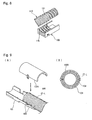
Fig. 8 ] A perspective view of an example of conventional art. - [
Fig. 9 ] (A) (B) Figures showing a case where a large-diameter convoluted conduit is inserted into a protector of another example of conventional art. - [
Fig. 10 ] (A) (B) Figures showing a case where a small-diameter convoluted conduit is inserted into the protector ofFig. 9 . - Hereinafter, embodiments of the present invention are described with reference to the drawings.
Figs. 1 to 6 illustrate a first embodiment. A predetermined area of awire harness 1 routed in an automobile is inserted through aprotector 2 formed of molded resin. Thewire harness 1 inserted into aninlet 2a, which is an opening at one end side in a length direction of theprotector 2, runs through a convoluted conduit 3 (a large-diameterconvoluted conduit 3L or a small-diameterconvoluted conduit 3S shown inFig. 6 ). Afront end 3a of theconvoluted conduit 3 internally engages and latches onto theprotector 2 on theinlet 2a side. In the interior of theprotector 2, thewire harness 1 is pulled out from thefront end 3a of the convoluted conduit. Thewire harness 1 is bound by aband clip 5 at a position between a central position in the length direction of theprotector 2 and anoutlet 2b, which is an opening on the other end side. Thewire harness 1 is pulled out from theoutlet 2b. - As shown in
Fig. 2 , theprotector 2 is configured with amain body 10 and alid 11. Themain body 10 shown inFig. 2(A) includes abottom wall 12, twoside walls bottom wall 12, and a dividingwall 14 in the middle. Abracket 15 protrudes from an outer surface of theside wall 13B to be fixated to other members. Thebracket 15 is provided with a latchingclip 16 and alock 17. A wireharness insertion path 18 is defined between theside wall 13A and the dividingwall 14. One end in the length direction of the wireharness insertion path 18 is theinlet 2a, and the other end is theoutlet 2b. Asplice housing 19 is defined between the dividingwall 14 and theside wall 13B. One end of thesplice housing 19 is provided with aclosed wall 19a, and the other end is anopening 19b for splice insertion. A width of the wireharness insertion path 18 is set to be wide, and at least twice a width of thesplice housing 19. - On the
inlet 2a side of the wireharness insertion path 18, a convolutedconduit engagement portion 20 is provided on internal surfaces of thebottom wall 12, theside wall 13A, and the dividingwall 14. The convolutedconduit engagement portion 20 has four protrudingU-shaped ribs 21 in an axis direction extending from an upper end of theside wall 13A to an upper end of the dividingwall 14. Theribs 21 are each in a circular arc shape having a diameter that precisely fitstroughs 45 of the large-diameterconvoluted conduit 3L and have a relatively low protrusion height. A pitch for crests and troughs of theconvoluted conduit 3 is substantially the same regardless of a diameter of theconvoluted conduit 3. Accordingly, the pitch for thetroughs 45 and crests 46 of the large-diameterconvoluted conduit 3L and the pitch fortroughs 40 and crests 41 of the small-diameterconvoluted conduit 3 S are the same. In addition, the pitch for theribs 21 provided to themain body 10 is also the same, which is a fixed pitch P. - Between the
outlet 2b and the central position in the length direction of the wireharness insertion path 18, a large, circulardownward protrusion 22 for clip latching is provided on thebottom wall 12. Further, arecess 22a is provided so as to recess from thebottom wall 12. In the center of therecess 22a, aclip latching hole 23 is pierced. - As described above, in the
wire harness 1 on theoutlet 2b side inside theprotector 2, a plurality of wires W are bound by theband clip 5. Theband clip 5 is a resin article formed by integrally molding aband 5a to be wrapped around the plurality of wires W, amain body 5b having theband 5a protruding therefrom and a hole through which the band passes, and a blade-shapedlatching portion 5c (clip) protruding from a lower surface of themain body 5b, as shown inFig. 4(B) . After being wrapped around the plurality of wires W, theband 5a is inserted into a through hole 5b1 of themain body 5b. Latching piece 5b2 protruding from an internal surface to the through hole 5b1 is latched onto a latching groove 5a1 provided to theband 5a so that the plurality of wires W are constricted and fixated. In the blade-shapedlatching portion 5c, a shaft 5c1 protrudes from a center of a plate 5c4 protruding from themain body 5b. A latching step 5c3 is provided to a distal end of a blade 5c2 that is provided to a distal end of the shaft 5c1 in a bent-back state. After the blade-shapedlatching portion 5c is inserted into theclip latching hole 23, the latching step 5c3 is latched and fixated onto a peripheral edge of theclip latching hole 23. - When attached to the
wire harness 1, theband clip 5 protrudes from thebottom wall 12 of the protector main body by the height of themain body 5b of theband clip 5. Accordingly, an upper surface of thewire harness 1 facing thelid 11 side becomes higher, and thus, it becomes difficult to close thelid 11 when thewire harness 1 has a large diameter. Therefore, the band clipmain body 5b is inserted into an interior of thedownward protrusion 22 provided to thebottom wall 12, and thereby, the height of the upper surface of thewire harness 1 is reduced. - Locking frames 25 that join and lock the
lid 11 are provided to both ends in the length direction of outer surfaces of the twoside walls main body 10 of theprotector 2. In other words, the locking frames 25 protrude from four corners of themain body 10. - The
lid 11 of theprotector 2 has a wide width, which is the same width as that of themain body 10. Thelid 11 is capable of sealing both the wireharness insertion path 18 and thesplice housing 19 in themain body 10 with anupper wall 30.Side walls 31 having a low height are provided to both side edges in the width direction of theupper wall 30. Lockingpieces 26 that are inserted and locked in the locking frames 25 protrude from both sides in the length direction of both theside walls 31. The lockingpieces 26 of thelid 11 and the locking frames 25 of themain body 10 are provided in positions in which they can lock in each other even when thelid 11 is rotated by 180 degrees as shown inFig. 2(B) . - A large-diameter convoluted
conduit engagement portion 33 and a small-diameter convolutedconduit engagement portion 35 protrude from diagonal positions and from each side in the length direction of a lower surface of theupper wall 30 of thelid 11 of theprotector 2. The large-diameter convolutedconduit engagement portion 33 is configured with four circular arc-shapedribs 34 each having a diameter and a height that fit thetroughs 45 of the large-diameterconvoluted conduit 3L. The small-diameter convolutedconduit engagement portion 35 is configured with four circular arc-shapedribs 36 each having a diameter and a height that fit thetroughs 40 of the small-diameterconvoluted conduit 3S. - In the following, mounting of the
wire harness 1, shown inFig. 5 , on theprotector 2 having themain body 10 and thelid 11 in the above-described shape is described. In thewire harness 1 that is inserted through theprotector 2, abranch line 1s having asplice 38 is branched off from a trunk line. Further, thewire harness 1 is pre-bound by theband clip 5 at a predetermined position. - As shown in
Fig. 6(A) , in a case where a convoluted conduit covering thewire harness 1 that is inserted into theinlet 2a of theprotector 2 is the large-diameterconvoluted conduit 3L, theribs 21 of themain body 10 are first inserted into thetroughs 45 for positioning. Further, the blade-shapedlatching portion 5c of theband clip 5 fastening thewire harness 1 is inserted into and latched onto theclip latching hole 23. Next, thelid 11 is placed such that the large-diameter convolutedconduit engagement portion 33 is on theinlet 2a side of themain body 10 and above the convolutedconduit engagement portion 20 of themain body 10; and theribs 34 are then inserted into the upper surface side of the large-diameterconvoluted conduit 3L. Thereby, theribs troughs 45 of the large-diameterconvoluted conduit 3L. Accordingly, the large-diameterconvoluted conduit 3L can be positioned and held between themain body 10 and thelid 11 while being prevented from shifting in the axial direction. In such a state, the lockingpieces 26 of thelid 11 are inserted and locked in the locking frames 25 of themain body 10 in order to fixate themain body 10 and thelid 11 to each other. Furthermore, thebranch line 1s branched off from thewire harness 1 and having thesplice 38 is branched off from the trunk line of thewire harness 1. Thesplice 38 is inserted into thesplice housing 19. - As shown in
Fig. 6(B) , in a case where a convoluted conduit covering thewire harness 1 is the small-diameterconvoluted conduit 3S, theribs 21 of the convolutedconduit engagement portion 20 of themain body 10 are inserted into thetroughs 40 of the small-diameterconvoluted conduit 3 S. At that point, a central portion of eachrib 21 protruding from thebottom wall 12 is inserted into thetroughs 40 of the small-diameterconvoluted conduit 3S while upper sides of both side portions of theribs 21 are off thetroughs 40. Theband clip 5 that is pre-bound on thewire harness 1 is inserted into and latched onto theclip latching hole 23 of thebottom wall 12. - Then, the
lid 11 is placed such that the small-diameter convolutedconduit engagement portion 35 is positioned on theinlet 2a side and faces the convolutedconduit engagement portion 20 of themain body 10 from above. In other words, thelid 11 is rotated by 180 degrees from the situation of the large-diameter convoluted conduit and is mounted on themain body 10. Theribs 36 of the small-diameter convolutedconduit engagement portion 35 of thelid 11 are accurately inserted into an upper surface side of thetroughs 40 of the small-diameterconvoluted conduit 3S. With theribs 36 being inserted into and pressing down thetroughs 40 on the upper surface side of the small-diameterconvoluted conduit 3S in such a way, theribs 21 on themain body 10 side engage with thetroughs 40 without position drift. Thereby, the small-diameterconvoluted conduit 3S is positioned and held in theprotector 2. Thereafter, the lockingpieces 26 of thelid 11 are inserted into and latched onto the locking frames 25 of themain body 10 for lock connection. The lockingpieces 26 and the locking frames 25 are provided in positions where the lockingpieces 26 can be inserted into and latched onto the locking frames 25 even when rotated by 180 degrees, which enables lock connection without difficulty. - In the present embodiment, the large-diameter
convoluted conduit 3L is ø32 mm, and the small-diameterconvoluted conduit 3S is ø28 mm. - As described above, in the above-described embodiment of the present invention, one type of the
protector 2 configured with onemain body 10 and onelid 11 can be used to accommodate different sizes, large and small, of convoluted conduit covering the wire harness. Therefore, it is not necessary to increase the types of the protectors based on the difference in diameters of the wire harness. -
Fig. 7 illustrates a second embodiment. A protector of the second embodiment does not include a splice housing but includes only the wireharness insertion path 18 in themain body 10 that has a relatively long trench shape. Thelid 11 has an oblong shape in accordance with themain body 10 and includes a large-diameter convolutedconduit engagement portion 33 and a small-diameter convolutedconduit engagement portion 35 on each side opposite to each other, not in a diagonal direction, but in a length direction. Other components are similar to the first embodiment. Thus, those components are provided with the same reference signs, and description thereof is omitted. - Further, when four types of convoluted conduits having ø24, 28, 32, and 36, respectively, are selectively used according to a diameter of a wire harness, two types of lids, a lid having convoluted conduit engagement portions for φ 24 and 28 on each side, respectively, and a lid having convoluted conduit engagement portions for
φ 32 and 36 on each side, respectively, may be provided. - Moreover, it is not required to fasten a wire harness inserted into the protector with a band clip and to latch a clip of the band clip onto a latching hole provided to a bottom wall of a main body. A wire harness pulled out from an outlet of the protector may be fixated by tape-winding onto a tape-winding piece provided to the outlet. In addition, instead of a band clip that fasten a wire harness, a board-type clip may be used which fixates a wire harness on a board by tape-winding.
-
- 1: Wire harness
- 2: Protector
- 2a: Inlet
- 2b: Outlet
- 3: Convoluted conduit
- 3L: Large-diameter convoluted conduit
- 3S: Small-diameter convoluted conduit
- 5: Band clip
- 10: Main body
- 11: Lid
- 12: Bottom wall
- 13A, 13B: Two side walls
- 14: Dividing wall
- 18: Wire harness insertion path
- 19: Splice housing
- 20: Convoluted conduit engagement portion
- 21: Rib
- 23: Clip latching hole
- 30: Upper Wall
- 33: Large-diameter convoluted conduit engagement portion
- 35: Small-diameter convoluted conduit engagement portion
- 34, 36: Rib
Claims (3)
- A protector that positions and holds, on an insertion inlet side, a convoluted conduit covering a wire harness, comprising:a main body having a bottom wall and two side walls; anda lid provided separately from the main body and covering an upper surface opening of the main body, whereinlocks capable of mutually connecting the main body and the lid are provided on both sides in a length direction of each of the main body and the lid and the locks of the lid are provided in symmetrical positions to enable connection with the locks of the main body even when the lid is rotated by 180 degrees;a convoluted conduit engagement portion having ribs that fit troughs of a large-diameter convoluted conduit extends from the bottom wall on one end side in the length direction of the main body to internal surfaces of the two side walls;a large-diameter convoluted conduit engagement portion having ribs that fit the troughs of the large-diameter convoluted conduit is provided on an internal surface on one end side in the length direction of the lid while a small-diameter convoluted conduit engagement portion having ribs that fit troughs of a small-diameter convoluted conduit is provided on an internal surface on the other end side; andthe convoluted conduit engagement portions on both the main body side and the lid side include a plurality of ribs having the same pitch and allow the lid to be rotated by 180 degrees to correspond to an outer diameter of an inserted convoluted conduit and to connect to the main body.
- The protector according to claim 1, wherein
the wire harness covered by the protector is inserted through the convoluted conduit on one end side of the protector while the wire harness on the other end side is bound by a band clip without being inserted through the convoluted conduit;
a recess for the band clip is provided to the bottom wall of the main body of the protector; and
a clip latching hole is provided in the center of the recess. - The protector according to either one of claim 1 and claim 2, wherein
a dividing wall is provided in the length direction in the middle of a width direction of the main body;
a wire harness insertion path is provided on one side divided by the dividing wall; the ribs are provided on the internal surface on one end side of the wire harness insertion path to define the convoluted conduit engagement portion;
a splice housing is provided on the other side of the dividing wall;
a width of the lid corresponds to a width of the main body; and
the large-diameter convoluted conduit engagement portion and the small-diameter convoluted conduit engagement portion are diagonally positioned.
Applications Claiming Priority (2)
| Application Number | Priority Date | Filing Date | Title |
|---|---|---|---|
| JP2011010955A JP5353908B2 (en) | 2011-01-21 | 2011-01-21 | Wire harness protector |
| PCT/JP2011/063646 WO2012098706A1 (en) | 2011-01-21 | 2011-06-15 | Wire harness protector |
Publications (3)
| Publication Number | Publication Date |
|---|---|
| EP2530798A1 true EP2530798A1 (en) | 2012-12-05 |
| EP2530798A4 EP2530798A4 (en) | 2014-06-11 |
| EP2530798B1 EP2530798B1 (en) | 2015-07-22 |
Family
ID=46515354
Family Applications (1)
| Application Number | Title | Priority Date | Filing Date |
|---|---|---|---|
| EP11855944.2A Not-in-force EP2530798B1 (en) | 2011-01-21 | 2011-06-15 | Wire harness protector |
Country Status (5)
| Country | Link |
|---|---|
| US (1) | US8847073B2 (en) |
| EP (1) | EP2530798B1 (en) |
| JP (1) | JP5353908B2 (en) |
| CN (1) | CN103314492B (en) |
| WO (1) | WO2012098706A1 (en) |
Cited By (1)
| Publication number | Priority date | Publication date | Assignee | Title |
|---|---|---|---|---|
| JPWO2017119139A1 (en) * | 2016-01-08 | 2018-08-16 | 三菱電機株式会社 | Air conditioner indoor unit |
Families Citing this family (33)
| Publication number | Priority date | Publication date | Assignee | Title |
|---|---|---|---|---|
| CN107102688B (en) * | 2012-01-24 | 2022-06-14 | 英特尔公司 | Mobile computing device, apparatus and system |
| JP5926144B2 (en) * | 2012-07-20 | 2016-05-25 | 矢崎総業株式会社 | Electric wire routing device |
| JP5928249B2 (en) * | 2012-08-29 | 2016-06-01 | トヨタ自動車株式会社 | Corrugated clamp |
| JP6002992B2 (en) * | 2012-10-15 | 2016-10-05 | 矢崎総業株式会社 | External protective tube for electric wire |
| CN107264440B (en) * | 2012-10-29 | 2019-11-15 | 古河电气工业株式会社 | wiring harness |
| JP6145356B2 (en) * | 2013-08-07 | 2017-06-07 | 矢崎総業株式会社 | Wire protection member |
| JP6209400B2 (en) * | 2013-08-29 | 2017-10-04 | 矢崎総業株式会社 | Analysis apparatus and program |
| US9162550B2 (en) * | 2013-10-08 | 2015-10-20 | Denso International America, Inc. | Wire harness mounting assembly |
| JPWO2015098684A1 (en) * | 2013-12-25 | 2017-03-23 | ニッタ株式会社 | Fitting cover |
| JP6135570B2 (en) * | 2014-03-20 | 2017-05-31 | 住友電装株式会社 | Wire harness |
| JP6134681B2 (en) * | 2014-03-24 | 2017-05-24 | ヤンマー株式会社 | engine |
| JP2016181961A (en) * | 2015-03-23 | 2016-10-13 | 矢崎総業株式会社 | Fixing structure of routing material and wire harness |
| JP6648661B2 (en) * | 2015-10-07 | 2020-02-14 | 住友電装株式会社 | Wire harness with protector |
| JP6488981B2 (en) * | 2015-10-13 | 2019-03-27 | 住友電装株式会社 | Electric wire routing device |
| JP6383345B2 (en) * | 2015-12-03 | 2018-08-29 | 矢崎総業株式会社 | Wire harness protector and method of manufacturing wire harness |
| JP6646874B2 (en) * | 2016-06-08 | 2020-02-14 | 住友電装株式会社 | Protector and wire harness |
| JP6793047B2 (en) * | 2017-01-25 | 2020-12-02 | 矢崎総業株式会社 | Protector and wire harness |
| JP6587657B2 (en) * | 2017-07-26 | 2019-10-09 | 矢崎総業株式会社 | Protector |
| US10688944B2 (en) * | 2017-08-24 | 2020-06-23 | Fca Us Llc | Integrated liftgate wire harness tether |
| JP6966263B2 (en) * | 2017-08-31 | 2021-11-10 | 矢崎総業株式会社 | Protector |
| JP6879474B2 (en) * | 2017-11-08 | 2021-06-02 | 住友電装株式会社 | Harness protector and harness assembly |
| JP7006512B2 (en) * | 2018-06-05 | 2022-02-10 | 株式会社オートネットワーク技術研究所 | Wire harness |
| JP7006556B2 (en) * | 2018-09-28 | 2022-01-24 | 住友電装株式会社 | Wiring member |
| DE102019101936A1 (en) * | 2019-01-25 | 2020-07-30 | Ebm-Papst Mulfingen Gmbh & Co. Kg | Cable magazine |
| JP6883595B2 (en) * | 2019-01-31 | 2021-06-09 | 矢崎総業株式会社 | Protective tube connection structure |
| DE112019007045T5 (en) * | 2019-03-19 | 2021-12-23 | Sumitomo Wiring Systems, Ltd. | Connection structure for housing component and protective tube |
| JP7028231B2 (en) | 2019-10-31 | 2022-03-02 | 住友電装株式会社 | Wire harness |
| JP7314790B2 (en) * | 2019-12-19 | 2023-07-26 | 住友電装株式会社 | protector and wire harness |
| CN113846470B (en) * | 2020-06-28 | 2023-12-19 | 上海海尔洗涤电器有限公司 | Cable trough structure and washing machine |
| KR20220092267A (en) * | 2020-12-24 | 2022-07-01 | 현대모비스 주식회사 | Battery system of vehicle |
| US12166337B2 (en) * | 2021-09-13 | 2024-12-10 | Sumitomo Wiring Systems, Ltd. | Connection structure for housing member and protective tube |
| JP7853155B2 (en) * | 2022-06-06 | 2026-04-28 | 矢崎総業株式会社 | Wire harness mounting structure |
| US20250180846A1 (en) * | 2023-11-30 | 2025-06-05 | Belden Canada Ulc | Cable adapter structurally configured to augment a cable diameter to enhance attachment with a component |
Family Cites Families (25)
| Publication number | Priority date | Publication date | Assignee | Title |
|---|---|---|---|---|
| FR1341867A (en) * | 1962-12-13 | 1963-11-02 | Floor distributor box for fluids and electric currents | |
| US3295806A (en) * | 1964-10-03 | 1967-01-03 | Modeme Robert | Two part clip for attaching a cylindrical member to a support |
| US3711632A (en) * | 1971-12-02 | 1973-01-16 | Gen Motors Corp | End fitting for corrugated conduit |
| JP2515735Y2 (en) * | 1990-11-21 | 1996-10-30 | 住友電装株式会社 | Wire harness connector cover |
| DE4204187C2 (en) * | 1992-02-13 | 1993-12-02 | Raymond A Gmbh & Co Kg | Cable duct for receiving cable bundles |
| JP2964445B2 (en) * | 1994-11-08 | 1999-10-18 | 矢崎総業株式会社 | Harness protector |
| CA2213152A1 (en) * | 1997-08-15 | 1999-02-15 | Glennon L. Defreitas | Junction box and lid for electrical conduits |
| JPH1169562A (en) * | 1997-08-21 | 1999-03-09 | Sumitomo Wiring Syst Ltd | Coupling member for sheathing material of wire harness |
| JP3583035B2 (en) * | 1999-09-06 | 2004-10-27 | 矢崎総業株式会社 | Cable protection protector |
| JP4092086B2 (en) * | 2000-06-30 | 2008-05-28 | 矢崎総業株式会社 | Corrugated tube fixture |
| JP3741999B2 (en) * | 2001-11-14 | 2006-02-01 | 矢崎総業株式会社 | Corrugated tube rotation holder |
| US6968864B2 (en) * | 2001-11-14 | 2005-11-29 | Yazaki Corporation | Rotary holder for corrugated tube |
| JP3894006B2 (en) * | 2002-03-15 | 2007-03-14 | 住友電装株式会社 | Wire harness protector |
| EP1363375B1 (en) * | 2002-05-14 | 2010-11-17 | Yazaki Corporation | Wire harness protector |
| US6747209B2 (en) * | 2002-06-19 | 2004-06-08 | Sumitomo Wiring Systems, Ltd. | Clamp |
| JP2005057968A (en) | 2003-08-07 | 2005-03-03 | Yazaki Corp | Harness fixing protector |
| JP4246032B2 (en) * | 2003-10-31 | 2009-04-02 | 矢崎総業株式会社 | Protector |
| JP4469648B2 (en) * | 2004-04-02 | 2010-05-26 | 矢崎総業株式会社 | Wire harness protector |
| JP4299211B2 (en) * | 2004-08-31 | 2009-07-22 | 住友電装株式会社 | Protector |
| JP2007228776A (en) * | 2006-02-27 | 2007-09-06 | Daiwa Kasei Ind Co Ltd | Protector for corrugated tube |
| JP4258529B2 (en) * | 2006-05-15 | 2009-04-30 | 住友電装株式会社 | Wire harness protector |
| JP4470932B2 (en) * | 2006-09-28 | 2010-06-02 | 住友電装株式会社 | Protector |
| DE102008022492B4 (en) * | 2007-05-07 | 2011-09-22 | Sumitomo Wiring Systems, Ltd. | guard |
| US7692095B2 (en) * | 2007-08-21 | 2010-04-06 | Yazaki Corporation | Wire harness lead-out structure of protector |
| JP5084019B2 (en) * | 2007-08-21 | 2012-11-28 | 矢崎総業株式会社 | Wire harness protector |
-
2011
- 2011-01-21 JP JP2011010955A patent/JP5353908B2/en not_active Expired - Fee Related
- 2011-06-15 CN CN201180065415.1A patent/CN103314492B/en not_active Expired - Fee Related
- 2011-06-15 US US13/577,031 patent/US8847073B2/en active Active
- 2011-06-15 EP EP11855944.2A patent/EP2530798B1/en not_active Not-in-force
- 2011-06-15 WO PCT/JP2011/063646 patent/WO2012098706A1/en not_active Ceased
Cited By (3)
| Publication number | Priority date | Publication date | Assignee | Title |
|---|---|---|---|---|
| JPWO2017119139A1 (en) * | 2016-01-08 | 2018-08-16 | 三菱電機株式会社 | Air conditioner indoor unit |
| EP3401616A4 (en) * | 2016-01-08 | 2019-01-09 | Mitsubishi Electric Corporation | INDOOR UNIT FOR AIR CONDITIONING DEVICE |
| US11047592B2 (en) | 2016-01-08 | 2021-06-29 | Mitsubishi Electric Corporation | Wire fastener for indoor unit of air-conditioning apparatus |
Also Published As
| Publication number | Publication date |
|---|---|
| JP2012152090A (en) | 2012-08-09 |
| JP5353908B2 (en) | 2013-11-27 |
| US8847073B2 (en) | 2014-09-30 |
| EP2530798B1 (en) | 2015-07-22 |
| CN103314492A (en) | 2013-09-18 |
| US20120298404A1 (en) | 2012-11-29 |
| WO2012098706A1 (en) | 2012-07-26 |
| EP2530798A4 (en) | 2014-06-11 |
| CN103314492B (en) | 2016-05-18 |
Similar Documents
| Publication | Publication Date | Title |
|---|---|---|
| EP2530798B1 (en) | Wire harness protector | |
| US10790655B2 (en) | Grommet | |
| US9136048B2 (en) | Wire harness protector | |
| US8987601B2 (en) | Partition-attached shield pipe and wire protection structure for end section thereof | |
| JP4258529B2 (en) | Wire harness protector | |
| US9539959B2 (en) | Structure for attaching band clip to corrugated tube | |
| EP2402218B1 (en) | Electric junction box | |
| US9124080B2 (en) | Wire accommodation protector | |
| WO2014125665A1 (en) | Clamping band fixing structure | |
| US20160248235A1 (en) | Protector for wire harness | |
| US9088091B2 (en) | Connector with wire cover | |
| US10486625B1 (en) | Grommet and wire harness | |
| US9102282B2 (en) | Wire harness protector | |
| US7760983B2 (en) | Distribution cable tray with a clamping collar receiver device | |
| US20160258555A1 (en) | Structure for attaching band clip to corrugated tube | |
| JP2013013177A (en) | Corrugate tube with pathway holding member and wire harness | |
| EP2405548A2 (en) | Electric junction box | |
| US8895860B2 (en) | Grommet | |
| JP2013005605A (en) | Corrugate tube with pathway holding member and wire harness | |
| US9825444B2 (en) | Electrical wire cover | |
| JP7746915B2 (en) | Wire harness fixing device and wire harness | |
| JP2015077011A (en) | Protective structure of wire harness branching section | |
| KR20100010252U (en) | Colgate tube structure |
Legal Events
| Date | Code | Title | Description |
|---|---|---|---|
| PUAI | Public reference made under article 153(3) epc to a published international application that has entered the european phase |
Free format text: ORIGINAL CODE: 0009012 |
|
| 17P | Request for examination filed |
Effective date: 20120823 |
|
| AK | Designated contracting states |
Kind code of ref document: A1 Designated state(s): AL AT BE BG CH CY CZ DE DK EE ES FI FR GB GR HR HU IE IS IT LI LT LU LV MC MK MT NL NO PL PT RO RS SE SI SK SM TR |
|
| DAX | Request for extension of the european patent (deleted) | ||
| REG | Reference to a national code |
Ref country code: DE Ref legal event code: R079 Ref document number: 602011018123 Country of ref document: DE Free format text: PREVIOUS MAIN CLASS: H02G0003040000 Ipc: B60R0016020000 |
|
| A4 | Supplementary search report drawn up and despatched |
Effective date: 20140509 |
|
| RIC1 | Information provided on ipc code assigned before grant |
Ipc: H02G 3/04 20060101ALI20140505BHEP Ipc: B60R 16/02 20060101AFI20140505BHEP Ipc: H02G 3/06 20060101ALI20140505BHEP |
|
| GRAP | Despatch of communication of intention to grant a patent |
Free format text: ORIGINAL CODE: EPIDOSNIGR1 |
|
| INTG | Intention to grant announced |
Effective date: 20150211 |
|
| GRAS | Grant fee paid |
Free format text: ORIGINAL CODE: EPIDOSNIGR3 |
|
| GRAA | (expected) grant |
Free format text: ORIGINAL CODE: 0009210 |
|
| AK | Designated contracting states |
Kind code of ref document: B1 Designated state(s): AL AT BE BG CH CY CZ DE DK EE ES FI FR GB GR HR HU IE IS IT LI LT LU LV MC MK MT NL NO PL PT RO RS SE SI SK SM TR |
|
| REG | Reference to a national code |
Ref country code: GB Ref legal event code: FG4D |
|
| REG | Reference to a national code |
Ref country code: CH Ref legal event code: EP |
|
| REG | Reference to a national code |
Ref country code: IE Ref legal event code: FG4D |
|
| REG | Reference to a national code |
Ref country code: AT Ref legal event code: REF Ref document number: 737687 Country of ref document: AT Kind code of ref document: T Effective date: 20150815 |
|
| REG | Reference to a national code |
Ref country code: DE Ref legal event code: R096 Ref document number: 602011018123 Country of ref document: DE |
|
| REG | Reference to a national code |
Ref country code: AT Ref legal event code: MK05 Ref document number: 737687 Country of ref document: AT Kind code of ref document: T Effective date: 20150722 |
|
| REG | Reference to a national code |
Ref country code: LT Ref legal event code: MG4D |
|
| REG | Reference to a national code |
Ref country code: NL Ref legal event code: MP Effective date: 20150722 |
|
| PG25 | Lapsed in a contracting state [announced via postgrant information from national office to epo] |
Ref country code: LV Free format text: LAPSE BECAUSE OF FAILURE TO SUBMIT A TRANSLATION OF THE DESCRIPTION OR TO PAY THE FEE WITHIN THE PRESCRIBED TIME-LIMIT Effective date: 20150722 Ref country code: FI Free format text: LAPSE BECAUSE OF FAILURE TO SUBMIT A TRANSLATION OF THE DESCRIPTION OR TO PAY THE FEE WITHIN THE PRESCRIBED TIME-LIMIT Effective date: 20150722 Ref country code: NO Free format text: LAPSE BECAUSE OF FAILURE TO SUBMIT A TRANSLATION OF THE DESCRIPTION OR TO PAY THE FEE WITHIN THE PRESCRIBED TIME-LIMIT Effective date: 20151022 Ref country code: LT Free format text: LAPSE BECAUSE OF FAILURE TO SUBMIT A TRANSLATION OF THE DESCRIPTION OR TO PAY THE FEE WITHIN THE PRESCRIBED TIME-LIMIT Effective date: 20150722 Ref country code: GR Free format text: LAPSE BECAUSE OF FAILURE TO SUBMIT A TRANSLATION OF THE DESCRIPTION OR TO PAY THE FEE WITHIN THE PRESCRIBED TIME-LIMIT Effective date: 20151023 |
|
| PG25 | Lapsed in a contracting state [announced via postgrant information from national office to epo] |
Ref country code: HR Free format text: LAPSE BECAUSE OF FAILURE TO SUBMIT A TRANSLATION OF THE DESCRIPTION OR TO PAY THE FEE WITHIN THE PRESCRIBED TIME-LIMIT Effective date: 20150722 Ref country code: PL Free format text: LAPSE BECAUSE OF FAILURE TO SUBMIT A TRANSLATION OF THE DESCRIPTION OR TO PAY THE FEE WITHIN THE PRESCRIBED TIME-LIMIT Effective date: 20150722 Ref country code: SE Free format text: LAPSE BECAUSE OF FAILURE TO SUBMIT A TRANSLATION OF THE DESCRIPTION OR TO PAY THE FEE WITHIN THE PRESCRIBED TIME-LIMIT Effective date: 20150722 Ref country code: IS Free format text: LAPSE BECAUSE OF FAILURE TO SUBMIT A TRANSLATION OF THE DESCRIPTION OR TO PAY THE FEE WITHIN THE PRESCRIBED TIME-LIMIT Effective date: 20151122 Ref country code: ES Free format text: LAPSE BECAUSE OF FAILURE TO SUBMIT A TRANSLATION OF THE DESCRIPTION OR TO PAY THE FEE WITHIN THE PRESCRIBED TIME-LIMIT Effective date: 20150722 Ref country code: PT Free format text: LAPSE BECAUSE OF FAILURE TO SUBMIT A TRANSLATION OF THE DESCRIPTION OR TO PAY THE FEE WITHIN THE PRESCRIBED TIME-LIMIT Effective date: 20151123 Ref country code: AT Free format text: LAPSE BECAUSE OF FAILURE TO SUBMIT A TRANSLATION OF THE DESCRIPTION OR TO PAY THE FEE WITHIN THE PRESCRIBED TIME-LIMIT Effective date: 20150722 Ref country code: RS Free format text: LAPSE BECAUSE OF FAILURE TO SUBMIT A TRANSLATION OF THE DESCRIPTION OR TO PAY THE FEE WITHIN THE PRESCRIBED TIME-LIMIT Effective date: 20150722 |
|
| REG | Reference to a national code |
Ref country code: DE Ref legal event code: R097 Ref document number: 602011018123 Country of ref document: DE |
|
| PG25 | Lapsed in a contracting state [announced via postgrant information from national office to epo] |
Ref country code: IT Free format text: LAPSE BECAUSE OF FAILURE TO SUBMIT A TRANSLATION OF THE DESCRIPTION OR TO PAY THE FEE WITHIN THE PRESCRIBED TIME-LIMIT Effective date: 20150722 Ref country code: DK Free format text: LAPSE BECAUSE OF FAILURE TO SUBMIT A TRANSLATION OF THE DESCRIPTION OR TO PAY THE FEE WITHIN THE PRESCRIBED TIME-LIMIT Effective date: 20150722 Ref country code: SK Free format text: LAPSE BECAUSE OF FAILURE TO SUBMIT A TRANSLATION OF THE DESCRIPTION OR TO PAY THE FEE WITHIN THE PRESCRIBED TIME-LIMIT Effective date: 20150722 Ref country code: EE Free format text: LAPSE BECAUSE OF FAILURE TO SUBMIT A TRANSLATION OF THE DESCRIPTION OR TO PAY THE FEE WITHIN THE PRESCRIBED TIME-LIMIT Effective date: 20150722 Ref country code: CZ Free format text: LAPSE BECAUSE OF FAILURE TO SUBMIT A TRANSLATION OF THE DESCRIPTION OR TO PAY THE FEE WITHIN THE PRESCRIBED TIME-LIMIT Effective date: 20150722 |
|
| PLBE | No opposition filed within time limit |
Free format text: ORIGINAL CODE: 0009261 |
|
| STAA | Information on the status of an ep patent application or granted ep patent |
Free format text: STATUS: NO OPPOSITION FILED WITHIN TIME LIMIT |
|
| PG25 | Lapsed in a contracting state [announced via postgrant information from national office to epo] |
Ref country code: RO Free format text: LAPSE BECAUSE OF FAILURE TO SUBMIT A TRANSLATION OF THE DESCRIPTION OR TO PAY THE FEE WITHIN THE PRESCRIBED TIME-LIMIT Effective date: 20150722 |
|
| 26N | No opposition filed |
Effective date: 20160425 |
|
| PG25 | Lapsed in a contracting state [announced via postgrant information from national office to epo] |
Ref country code: SI Free format text: LAPSE BECAUSE OF FAILURE TO SUBMIT A TRANSLATION OF THE DESCRIPTION OR TO PAY THE FEE WITHIN THE PRESCRIBED TIME-LIMIT Effective date: 20150722 |
|
| PG25 | Lapsed in a contracting state [announced via postgrant information from national office to epo] |
Ref country code: BE Free format text: LAPSE BECAUSE OF FAILURE TO SUBMIT A TRANSLATION OF THE DESCRIPTION OR TO PAY THE FEE WITHIN THE PRESCRIBED TIME-LIMIT Effective date: 20150722 |
|
| PG25 | Lapsed in a contracting state [announced via postgrant information from national office to epo] |
Ref country code: MC Free format text: LAPSE BECAUSE OF FAILURE TO SUBMIT A TRANSLATION OF THE DESCRIPTION OR TO PAY THE FEE WITHIN THE PRESCRIBED TIME-LIMIT Effective date: 20150722 |
|
| REG | Reference to a national code |
Ref country code: CH Ref legal event code: PL |
|
| GBPC | Gb: european patent ceased through non-payment of renewal fee |
Effective date: 20160615 |
|
| REG | Reference to a national code |
Ref country code: IE Ref legal event code: MM4A |
|
| REG | Reference to a national code |
Ref country code: FR Ref legal event code: ST Effective date: 20170228 |
|
| PG25 | Lapsed in a contracting state [announced via postgrant information from national office to epo] |
Ref country code: LI Free format text: LAPSE BECAUSE OF NON-PAYMENT OF DUE FEES Effective date: 20160630 Ref country code: FR Free format text: LAPSE BECAUSE OF NON-PAYMENT OF DUE FEES Effective date: 20160630 Ref country code: CH Free format text: LAPSE BECAUSE OF NON-PAYMENT OF DUE FEES Effective date: 20160630 |
|
| PG25 | Lapsed in a contracting state [announced via postgrant information from national office to epo] |
Ref country code: IE Free format text: LAPSE BECAUSE OF NON-PAYMENT OF DUE FEES Effective date: 20160615 Ref country code: GB Free format text: LAPSE BECAUSE OF NON-PAYMENT OF DUE FEES Effective date: 20160615 |
|
| PG25 | Lapsed in a contracting state [announced via postgrant information from national office to epo] |
Ref country code: NL Free format text: LAPSE BECAUSE OF FAILURE TO SUBMIT A TRANSLATION OF THE DESCRIPTION OR TO PAY THE FEE WITHIN THE PRESCRIBED TIME-LIMIT Effective date: 20150722 |
|
| PG25 | Lapsed in a contracting state [announced via postgrant information from national office to epo] |
Ref country code: CY Free format text: LAPSE BECAUSE OF FAILURE TO SUBMIT A TRANSLATION OF THE DESCRIPTION OR TO PAY THE FEE WITHIN THE PRESCRIBED TIME-LIMIT Effective date: 20150722 Ref country code: HU Free format text: LAPSE BECAUSE OF FAILURE TO SUBMIT A TRANSLATION OF THE DESCRIPTION OR TO PAY THE FEE WITHIN THE PRESCRIBED TIME-LIMIT; INVALID AB INITIO Effective date: 20110615 Ref country code: SM Free format text: LAPSE BECAUSE OF FAILURE TO SUBMIT A TRANSLATION OF THE DESCRIPTION OR TO PAY THE FEE WITHIN THE PRESCRIBED TIME-LIMIT Effective date: 20150722 |
|
| PG25 | Lapsed in a contracting state [announced via postgrant information from national office to epo] |
Ref country code: LU Free format text: LAPSE BECAUSE OF NON-PAYMENT OF DUE FEES Effective date: 20160615 Ref country code: MK Free format text: LAPSE BECAUSE OF FAILURE TO SUBMIT A TRANSLATION OF THE DESCRIPTION OR TO PAY THE FEE WITHIN THE PRESCRIBED TIME-LIMIT Effective date: 20150722 Ref country code: MT Free format text: LAPSE BECAUSE OF NON-PAYMENT OF DUE FEES Effective date: 20160630 Ref country code: TR Free format text: LAPSE BECAUSE OF FAILURE TO SUBMIT A TRANSLATION OF THE DESCRIPTION OR TO PAY THE FEE WITHIN THE PRESCRIBED TIME-LIMIT Effective date: 20150722 |
|
| PG25 | Lapsed in a contracting state [announced via postgrant information from national office to epo] |
Ref country code: BG Free format text: LAPSE BECAUSE OF FAILURE TO SUBMIT A TRANSLATION OF THE DESCRIPTION OR TO PAY THE FEE WITHIN THE PRESCRIBED TIME-LIMIT Effective date: 20150722 |
|
| PG25 | Lapsed in a contracting state [announced via postgrant information from national office to epo] |
Ref country code: AL Free format text: LAPSE BECAUSE OF FAILURE TO SUBMIT A TRANSLATION OF THE DESCRIPTION OR TO PAY THE FEE WITHIN THE PRESCRIBED TIME-LIMIT Effective date: 20150722 |
|
| REG | Reference to a national code |
Ref country code: DE Ref legal event code: R084 Ref document number: 602011018123 Country of ref document: DE |
|
| P01 | Opt-out of the competence of the unified patent court (upc) registered |
Effective date: 20230517 |
|
| PGFP | Annual fee paid to national office [announced via postgrant information from national office to epo] |
Ref country code: DE Payment date: 20230502 Year of fee payment: 13 |
|
| REG | Reference to a national code |
Ref country code: DE Ref legal event code: R119 Ref document number: 602011018123 Country of ref document: DE |
|
| PG25 | Lapsed in a contracting state [announced via postgrant information from national office to epo] |
Ref country code: DE Free format text: LAPSE BECAUSE OF NON-PAYMENT OF DUE FEES Effective date: 20250101 |