EP2530733A1 - Terminal box for solar cell module, and solar cell module - Google Patents
Terminal box for solar cell module, and solar cell module Download PDFInfo
- Publication number
- EP2530733A1 EP2530733A1 EP11736926A EP11736926A EP2530733A1 EP 2530733 A1 EP2530733 A1 EP 2530733A1 EP 11736926 A EP11736926 A EP 11736926A EP 11736926 A EP11736926 A EP 11736926A EP 2530733 A1 EP2530733 A1 EP 2530733A1
- Authority
- EP
- European Patent Office
- Prior art keywords
- solar cell
- main body
- cell module
- box main
- connection
- Prior art date
- Legal status (The legal status is an assumption and is not a legal conclusion. Google has not performed a legal analysis and makes no representation as to the accuracy of the status listed.)
- Withdrawn
Links
Images




Classifications
-
- H—ELECTRICITY
- H02—GENERATION; CONVERSION OR DISTRIBUTION OF ELECTRIC POWER
- H02G—INSTALLATION OF ELECTRIC CABLES OR LINES, OR OF COMBINED OPTICAL AND ELECTRIC CABLES OR LINES
- H02G3/00—Installations of electric cables or lines or protective tubing therefor in or on buildings, equivalent structures or vehicles
- H02G3/02—Details
- H02G3/08—Distribution boxes; Connection or junction boxes
- H02G3/16—Distribution boxes; Connection or junction boxes structurally associated with support for line-connecting terminals within the box
-
- H—ELECTRICITY
- H02—GENERATION; CONVERSION OR DISTRIBUTION OF ELECTRIC POWER
- H02G—INSTALLATION OF ELECTRIC CABLES OR LINES, OR OF COMBINED OPTICAL AND ELECTRIC CABLES OR LINES
- H02G15/00—Cable fittings
- H02G15/013—Sealing means for cable inlets
-
- H—ELECTRICITY
- H02—GENERATION; CONVERSION OR DISTRIBUTION OF ELECTRIC POWER
- H02G—INSTALLATION OF ELECTRIC CABLES OR LINES, OR OF COMBINED OPTICAL AND ELECTRIC CABLES OR LINES
- H02G15/00—Cable fittings
- H02G15/02—Cable terminations
- H02G15/04—Cable-end sealings
-
- H—ELECTRICITY
- H02—GENERATION; CONVERSION OR DISTRIBUTION OF ELECTRIC POWER
- H02S—GENERATION OF ELECTRIC POWER BY CONVERSION OF INFRARED RADIATION, VISIBLE LIGHT OR ULTRAVIOLET LIGHT, e.g. USING PHOTOVOLTAIC [PV] MODULES
- H02S40/00—Components or accessories in combination with PV modules, not provided for in groups H02S10/00 - H02S30/00
- H02S40/30—Electrical components
- H02S40/34—Electrical components comprising specially adapted electrical connection means to be structurally associated with the PV module, e.g. junction boxes
- H02S40/345—Electrical components comprising specially adapted electrical connection means to be structurally associated with the PV module, e.g. junction boxes with cooling means associated with the electrical connection means, e.g. cooling means associated with or applied to the junction box
-
- Y—GENERAL TAGGING OF NEW TECHNOLOGICAL DEVELOPMENTS; GENERAL TAGGING OF CROSS-SECTIONAL TECHNOLOGIES SPANNING OVER SEVERAL SECTIONS OF THE IPC; TECHNICAL SUBJECTS COVERED BY FORMER USPC CROSS-REFERENCE ART COLLECTIONS [XRACs] AND DIGESTS
- Y02—TECHNOLOGIES OR APPLICATIONS FOR MITIGATION OR ADAPTATION AGAINST CLIMATE CHANGE
- Y02E—REDUCTION OF GREENHOUSE GAS [GHG] EMISSIONS, RELATED TO ENERGY GENERATION, TRANSMISSION OR DISTRIBUTION
- Y02E10/00—Energy generation through renewable energy sources
- Y02E10/50—Photovoltaic [PV] energy
Definitions
- the present invention relates to a terminal box for solar cell module to be attached to a solar cell module for connecting the module with another solar cell module.
- the invention also relates to a solar cell module using the terminal box.
- Solar power generation systems are gathering attention in recent years as environmentally friendly power generation systems, from increasing awareness in environmental issues.
- One form of such solar power generation systems is a solar-light power-generation system which uses solar cell modules installed in a matrix pattern on a roof of a building for example.
- each solar cell module has a terminal box attached thereto, in order to provide electrical connection to adjacent solar cell modules as well as to extract electrical power which is generated by each solar cell module (see Patent Literature 1).
- the terminal box for solar cell module includes a box main body which has a plurality of terminals inside the box main body, for electrical connection to output terminals of the solar cell modules. Each of these terminals is electrically connected to an end of an external-connection cable, with the other end of the cable being connected to a cable from another terminal box for solar cell module for example.
- insulating resin such as silicone resin is used as a sealing resin to fill inside of the box main body to ensure waterproofing capability and insulating capability of the terminal box for solar cell module.
- the above-described external-connection cables have an outer coat which is made of insulating resin such as cross-linked polyethylene.
- the outer coat of the external-connection cable and silicone resin for example, are not bonded strongly enough to each other and further, small gaps between the cable and the surrounds are not filled completely with silicone resin. Therefore, the terminal box cannot maintain its waterproofing function to a sufficient level, and the terminal box is subject to such troubles as water finding its way into the terminal box.
- An object of the present invention is to provide a terminal box for solar cell module capable of ensuring waterproofing capability and insulating capability without requiring separate members such as packings.
- the present invention provides a terminal box for a solar cell module, which includes: a box main body to be attached to the solar cell module; a plurality of connection terminals arranged inside the box main body for connection to a plurality of end ribbons from solar cells in the solar cell module; external-connection cables each having an end which is connected to a corresponding one of the connection terminals and another end which is drawn out of the box main body; and cable through-holes in the box main body for routing the external-connection cables into the box main body.
- the box main body has a resin pocket for a filler resin, at a region where the external-connection cable is inserted.
- the resin pocket may be made inside the cable through-hole.
- the resin pocket may be made near a connection area between the cable through-hole and an inside of the box main body.
- a solar cell module includes: a front surface member; a rear surface member; a plurality of solar cells disposed between the front surface member and the rear surface member; a sealing member sealing the solar cells between the front surface member and the rear surface member; and the-above described terminal box for solar cell module, attached to the rear surface member.
- the present invention includes a resin pocket for a filler resin, at a region where the external-connection cable is inserted. This ensures that the filler resin fills completely, thereby preventing water, for example, from finding its way into the through-hole.
- Fig. 1 is a plan view which shows a solar cell module with a terminal box according to the present invention attached thereto.
- Fig. 2 is a plan view which shows a primary portion of a solar cell panel to which the terminal box according to the present invention is attached.
- a solar cell module 1 to which a terminal box according to the present invention is attached includes a solar cell panel 10 which has a plurality of solar cells 11 ... therein; and a frame 20 attached therearound.
- Each solar cell 11 is made of crystalline semiconductors provided by monocrystal silicon and polycrystal silicon having a thickness of 0.15 mm for example in a substantially square shape having a side of 100 mm approx.
- the present invention is not limited to this, and the solar cells may be of a different type.
- the solar cell 11 has, for example, an n-type region and p-type region formed therein.
- a junction is formed in the interface between the n-type region and the p-type region, for formation of an electric field to separate carriers.
- the solar cell used in this embodiment may have an arrangement, for example, that a substantially intrinsic amorphous silicon layer is placed between a monocrystal silicon substrate and an amorphous silicon layer for reduced defect in the interface therebetween and improved characteristics of a hetero junction interface.
- Each of these solar cells 11 is electrically connected with the adjacent solar cells 11 with ribbons 102 which are made of flat copper foils for example.
- each ribbon has its first-end side connected to an upper surface side electrode of a certain solar cell 11 while its second-end side is connected to a lower surface side electrode of another solar cell 11 adjoining the certain solar cell.
- These solar cells 11 ... are connected in series by the ribbons 102, to form a string 110, and these strings 110, 110 are connected with each other by bus ribbons 111.
- the strings 110 are connected to end ribbons 112, so that a predetermined level of output, of 200 Watts for example, is drawn from the solar cell module 1 via the end ribbons 112.
- the solar cell panel 10 includes a plurality of solar cells 11 sealed between a transparent front surface member such as glass or transparent plastic and a rear surface member which is provided by a weather resistant film as a weather resistance member, made by sandwiching a metal foil on the rear side between insulating films, or a transparent member such as glass or transparent plastic, using a sealing member 14 which has good weather resistance and moisture resistance such as EVA (ethylene vinyl acetate).
- a transparent front surface member such as glass or transparent plastic
- a rear surface member which is provided by a weather resistant film as a weather resistance member, made by sandwiching a metal foil on the rear side between insulating films, or a transparent member such as glass or transparent plastic, using a sealing member 14 which has good weather resistance and moisture resistance such as EVA (ethylene vinyl acetate).
- EVA ethylene vinyl acetate
- the terminal box 30 is attached to the rear surface member, near the frame 20 of the solar cell panel 10, using an adhesive or the like.
- Fig. 2 shows the terminal box 30 in a simplified manner without details of the terminals, etc.
- the terminal box 30 includes a box main body 31 having therein connection terminals 33a through 33e provided correspondingly to the end ribbons from the solar cell panel 10.
- connection terminals 33a through 33e ribbon holes 38 ... are formed in a bottom of the box main body 31 for insertion of the end ribbons.
- through-holes are formed on two side surfaces of the box main body 31 for insertion of external-connection cables 17.
- connection terminals are provided for four end ribbons 112 ....
- the end ribbons are not connected to the connection terminals 33c, so the connection terminals 33c and the connection terminals 33d are connected with each other with a jumper wire 35.
- a bypass diode 34 is connected at each of the following places; across the connection terminals 33a and 33b, across the connection terminals 33a and 33b, and across the connection terminals 33d and 33e.
- connection between the terminal box 30 and the end ribbons 112 from the solar cell panel 10 is made as follows: Through the ribbon holes 38 ..., the end ribbons 112 ...are introduced inside, and each of the end ribbons 112 ...is soldered to one of the connection terminals 33a, 33b, 33d, 33e. Then, the cables 17 inserted into the connection terminal 33a via the through-holes are rigidly fixed by cable swaging for example. Likewise, the cables 17 inserted into the connection terminal 33e via the through-hole are rigidly fixed by cable swaging for example.
- the end ribbons 112 from the solar cell panel 10 are connected in series by using the terminal box 30, so that a cable 17 for a positive terminal and a cable 17 for a negative terminal are drawn out of the terminal box 30.
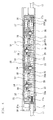
- Fig. 3 is a side view of a terminal box for solar cell module according to the first embodiment of the present invention, with half of the side shown in a sectional view whereas Fig. 4 is a plan view of the terminal box, showing a state where its lid portion is removed, with part of a cable through-hole shown as a sectional view.
- this terminal box 30 for solar cell module according to the first embodiment is attached to a rear surface of a solar cell panel 10 which includes a plurality of solar cells connected electrically in series.
- the terminal box 30 is made of a synthetic resin by molding for example, and includes a box main body 31 which has a holding recess 37 inside itself, and a platy lid member 32 which closes the holding recess 37.
- the box main body 31 is structured as a rectangular case with its upper surface open to the outside.
- the lid member 32 is attached on the upper surface side of the box main body 31.
- the terminal box 30 is attached by bonding the lower surface of the box main body 31 to the rear surface member of the solar cell panel 10 by using an adhesive. Also, for purposes of waterproofing, moisture prevention, heat dissipation, water condensation prevention, etc. , silicone resin is used to fill the holding recess 37 as a filler resin, and then the lid member 32 is fitted securely.
- the box main body 31 has a bottom formed with the ribbon holes 38 through which the end ribbons from the solar cell panel 10 are inserted. Also, cable through-holes 36 are formed on left and right ends of the box main body 31 for insertion of external-connection cables 17.
- connection terminals 33a through 33e are erected side by side in the left-right direction from the bottom surface, correspondingly to the ribbon holes 38, between the cable through-hole 36, 36 in the box main body 31.
- connection of the cables 17 are made by, first, fitting core wire portions 17b of the cables 17 into connection portions of the respective left and right connection terminals 33a, 33e and then tightly fixing the portions.
- edge portions of the plural end ribbons from the solar cell panel 10 are inserted into the box main body 31 through the ribbon holes 38, and then soldered to edge portions of the respective connection terminals 33a through 33e.
- connection terminals 33a through 33e metal heat dissipation plates 35 ... are formed so as to connect with the connection terminals.
- Bypass diodes 34 each working as a rectifier for a bypass are disposed across two metal heat dissipation plates 35. These bypass diodes 34 are connected across the connection terminal.
- Heat generated in the bypass diodes 34 is dissipated through the heat dissipation plates 35, so the arrangement can effectively prevent localized hot spots.
- the heat dissipation plates 35 provide heat removal from increased area, achieving improvement in heat dissipation capabilities. This improves durability of the bypass diodes 34, etc., offering an advantage of improved long term reliability of the bypass diodes 34, and of the solar cell module in this regard.
- the cables 17 are inserted through the through-holes 36 and then into the box main body 31. Then, the cables 17 are fixed to the box main body 31 of the terminal box 30 with unillustrated cable fasteners.
- the cables 17 have an outer coat 17a made of cross-linked polyethylene, for example.
- Cross-linked polyethylene does not provide good bonding to silicone resin and in addition does not easily find its way into narrow gaps.
- silicone pockets 37a are provided inside the through-holes 36 in the present embodiment to ensure that silicone resin will fill sufficiently.
- the through-holes 36 are given a sufficiently larger inner diameter than an outer diameter of the cables 17, to form the silicone pockets 37a so that silicone resin will flow from the holding recess 37 of the box main body 31 and fill the space.
- the core wire portions 17a of the cables 17 are first connected two the connection terminals 33a (33e)). Subsequently, the holding recess 37 of the box main body 31 is filled with silicone resin.
- the silicone resin flows between the through-hole 36 and the outer coat 17a of the cable 17, and fills the silicone pockets 37a sufficiently. As a result, gaps between the through-hole 36 and the cable 17 are filled with silicone resin, reliably preventing entry of water etc. from the through-holes 36.
- Fig. 5 is a side view of a terminal box for solar cell module according to the second embodiment of the present invention, with half of the side shown in a sectional view. It should be noted here that the same or equivalent parts and components as in the first embodiment will be indicated with the same reference symbols, and in order two avoid redundancy, their description will not be repeated hereafter.
- a silicone pocket 37b in the second embodiment is formed near the connection area between the through-hole 36 for the cable 17 and inside (the holding recess 37) of the box main body 31.
- the silicone pocket 37b is formed by enlarging a lower region of the box main body 31 which faces the through-hole 36 of the box main body 31.
- the silicone pocket 37b ensures that the inside space of the box main body 31 facing the through-whole 36 is sufficiently filled with silicone resin.
- the arrangement reliably prevents water which happens to find its way from any gap between the through-holes 36 and the cables 17, by the silicone resin which completely fills up the silicone pocket 37b.
- the through-hole 36 has a slightly greater inner diameter than an outer diameter of the cables 17.
- a silicone pocket 17a may be provided inside the through-hole 36.
- the combination of the silicone pocket 37a inside the through-hole 36 and the silicone pocket 37b inside the box main body 31 enhances waterproofing capability.
- Fig. 7 is a side view of a terminal box for solar cell module according to the third embodiment of the present invention, with half of the side shown in a sectional view.
- Fig. 8 is a plan view of the terminal box, showing a state where its lid portion is removed, with part of a cable through-hole shown in a sectional view.
- the same or equivalent parts and components as in the first embodiment will be indicated with the same reference symbols, and in order to avoid redundancy, their description will not be repeated hereafter.
- the third embodiment uses an arrangement where the core wire portion 17b of the cable 17 comes inside the through-hole 36, and a silicone pocket 37c is formed between the core wire portion 17b of the cable 17 and an inner wall of the through-hole 36.
- the core wire portion 17b of the cable 17 makes contact with silicone resin inside the through-hole 36. Bonding strength between the core wire portion 17b and silicone resin is better than that between the outer coat 17a of the cable 17 and silicone resin, and therefore the arrangement provides more improved waterproofing capability than the first and the second embodiments.
Landscapes
- Engineering & Computer Science (AREA)
- Architecture (AREA)
- Civil Engineering (AREA)
- Structural Engineering (AREA)
- Photovoltaic Devices (AREA)
- Cable Accessories (AREA)
Abstract
Description
- The present invention relates to a terminal box for solar cell module to be attached to a solar cell module for connecting the module with another solar cell module. The invention also relates to a solar cell module using the terminal box.
- Solar power generation systems are gathering attention in recent years as environmentally friendly power generation systems, from increasing awareness in environmental issues. One form of such solar power generation systems is a solar-light power-generation system which uses solar cell modules installed in a matrix pattern on a roof of a building for example. In such a solar power generation system, each solar cell module has a terminal box attached thereto, in order to provide electrical connection to adjacent solar cell modules as well as to extract electrical power which is generated by each solar cell module (see Patent Literature 1).
- The terminal box for solar cell module includes a box main body which has a plurality of terminals inside the box main body, for electrical connection to output terminals of the solar cell modules. Each of these terminals is electrically connected to an end of an external-connection cable, with the other end of the cable being connected to a cable from another terminal box for solar cell module for example.
- In the above-described conventional terminal box for solar cell module, insulating resin such as silicone resin is used as a sealing resin to fill inside of the box main body to ensure waterproofing capability and insulating capability of the terminal box for solar cell module.
-
- [Patent Literature 1]
JP-A 2001-77391 - The above-described external-connection cables have an outer coat which is made of insulating resin such as cross-linked polyethylene. However, the outer coat of the external-connection cable and silicone resin, for example, are not bonded strongly enough to each other and further, small gaps between the cable and the surrounds are not filled completely with silicone resin. Therefore, the terminal box cannot maintain its waterproofing function to a sufficient level, and the terminal box is subject to such troubles as water finding its way into the terminal box.
- In order to prevent the water troubles, members such as packings and O rings are sometimes attached to the cable. However, these solutions have problems, including that it requires separate members such as packings; that it requires additional steps of assembly; and that it increases cost.
- An object of the present invention is to provide a terminal box for solar cell module capable of ensuring waterproofing capability and insulating capability without requiring separate members such as packings.
- The present invention provides a terminal box for a solar cell module, which includes: a box main body to be attached to the solar cell module; a plurality of connection terminals arranged inside the box main body for connection to a plurality of end ribbons from solar cells in the solar cell module; external-connection cables each having an end which is connected to a corresponding one of the connection terminals and another end which is drawn out of the box main body; and cable through-holes in the box main body for routing the external-connection cables into the box main body. With this arrangement, the box main body has a resin pocket for a filler resin, at a region where the external-connection cable is inserted.
- The resin pocket may be made inside the cable through-hole.
- Also, the resin pocket may be made near a connection area between the cable through-hole and an inside of the box main body.
- A solar cell module according to the present invention includes: a front surface member; a rear surface member; a plurality of solar cells disposed between the front surface member and the rear surface member; a sealing member sealing the solar cells between the front surface member and the rear surface member; and the-above described terminal box for solar cell module, attached to the rear surface member.
- The present invention includes a resin pocket for a filler resin, at a region where the external-connection cable is inserted. This ensures that the filler resin fills completely, thereby preventing water, for example, from finding its way into the through-hole.
-
-
Fig. 1 is a plan view which shows a solar cell module with a terminal box according to the present invention attached thereto. -
Fig. 2 is a plan view which shows a primary portion of a solar cell panel to which the terminal box according to the present invention is attached. -
Fig. 3 is a side view of a terminal box for solar cell module according to a first embodiment of the present invention, with half of the side shown in a sectional view. -
Fig. 4 is a plan view of the terminal box for solar cell module according to the first embodiment of the present invention, showing a state where its lid portion is removed, with part of a cable through-hole shown in a sectional view. -
Fig. 5 is a side view of a terminal box for solar cell module according to a second embodiment of the present invention, with half of the side shown in a sectional view. -
Fig. 6 is a side view of a variation of the terminal box for solar cell module according to the second embodiment of the present invention, with half of the side shown in a sectional view. -
Fig. 7 is a side view of a terminal box for solar cell modules according to a third embodiment of the present invention, with half of the side shown in a section. -
Fig. 8 is a plan view of the terminal box for solar cell module according to the third embodiment of the present invention, showing a state where its lid portion is removed. - Embodiments of the present invention will be described in detail with reference to the drawings. It should be noted here that throughout the drawings the same or equivalent parts and components will be indicated with the same reference symbols, and in order to avoid redundancy in description, their description will not be repeated.
- First, a solar cell module to which a terminal box according to the present invention is attached will be described with reference to
Fig. 1 andFig. 2 .Fig. 1 is a plan view which shows a solar cell module with a terminal box according to the present invention attached thereto.Fig. 2 is a plan view which shows a primary portion of a solar cell panel to which the terminal box according to the present invention is attached. - A
solar cell module 1 to which a terminal box according to the present invention is attached includes asolar cell panel 10 which has a plurality ofsolar cells 11 ... therein; and aframe 20 attached therearound. Eachsolar cell 11 is made of crystalline semiconductors provided by monocrystal silicon and polycrystal silicon having a thickness of 0.15 mm for example in a substantially square shape having a side of 100 mm approx. However, the present invention is not limited to this, and the solar cells may be of a different type. - The
solar cell 11 has, for example, an n-type region and p-type region formed therein. A junction is formed in the interface between the n-type region and the p-type region, for formation of an electric field to separate carriers. The solar cell used in this embodiment may have an arrangement, for example, that a substantially intrinsic amorphous silicon layer is placed between a monocrystal silicon substrate and an amorphous silicon layer for reduced defect in the interface therebetween and improved characteristics of a hetero junction interface. - Each of these
solar cells 11 is electrically connected with the adjacentsolar cells 11 withribbons 102 which are made of flat copper foils for example. Specifically, each ribbon has its first-end side connected to an upper surface side electrode of a certainsolar cell 11 while its second-end side is connected to a lower surface side electrode of anothersolar cell 11 adjoining the certain solar cell. Thesesolar cells 11 ... are connected in series by theribbons 102, to form astring 110, and thesestrings bus ribbons 111. Also, thestrings 110 are connected toend ribbons 112, so that a predetermined level of output, of 200 Watts for example, is drawn from thesolar cell module 1 via theend ribbons 112. Also, thesolar cell panel 10 includes a plurality ofsolar cells 11 sealed between a transparent front surface member such as glass or transparent plastic and a rear surface member which is provided by a weather resistant film as a weather resistance member, made by sandwiching a metal foil on the rear side between insulating films, or a transparent member such as glass or transparent plastic, using a sealing member 14 which has good weather resistance and moisture resistance such as EVA (ethylene vinyl acetate). - As shown in
Fig. 1 andFig. 2 , theterminal box 30 is attached to the rear surface member, near theframe 20 of thesolar cell panel 10, using an adhesive or the like. -
Fig. 2 shows theterminal box 30 in a simplified manner without details of the terminals, etc. Theterminal box 30 includes a boxmain body 31 having thereinconnection terminals 33a through 33e provided correspondingly to the end ribbons from thesolar cell panel 10. Correspondingly to theseconnection terminals 33a through 33e,ribbon holes 38 ... are formed in a bottom of the boxmain body 31 for insertion of the end ribbons. Also, through-holes (unillustrated) are formed on two side surfaces of the boxmain body 31 for insertion of external-connection cables 17. - In the embodiment in
Fig. 2 , five connection terminals are provided for fourend ribbons 112 .... In this embodiment, the end ribbons are not connected to theconnection terminals 33c, so theconnection terminals 33c and theconnection terminals 33d are connected with each other with ajumper wire 35. Abypass diode 34 is connected at each of the following places; across theconnection terminals connection terminals connection terminals - With the above, connection between the
terminal box 30 and theend ribbons 112 from thesolar cell panel 10 is made as follows: Through theribbon holes 38 ..., theend ribbons 112 ...are introduced inside, and each of theend ribbons 112 ...is soldered to one of theconnection terminals cables 17 inserted into theconnection terminal 33a via the through-holes are rigidly fixed by cable swaging for example. Likewise, thecables 17 inserted into theconnection terminal 33e via the through-hole are rigidly fixed by cable swaging for example. - Following these steps, the
end ribbons 112 from thesolar cell panel 10 are connected in series by using theterminal box 30, so that acable 17 for a positive terminal and acable 17 for a negative terminal are drawn out of theterminal box 30. - Next, a terminal box for solar cell module according to a first embodiment of the present invention will be described with reference to
Fig. 3 andFig. 4 .Fig. 3 is a side view of a terminal box for solar cell module according to the first embodiment of the present invention, with half of the side shown in a sectional view whereasFig. 4 is a plan view of the terminal box, showing a state where its lid portion is removed, with part of a cable through-hole shown as a sectional view. - Like the example described thus far, this
terminal box 30 for solar cell module according to the first embodiment is attached to a rear surface of asolar cell panel 10 which includes a plurality of solar cells connected electrically in series. - The
terminal box 30 is made of a synthetic resin by molding for example, and includes a boxmain body 31 which has a holdingrecess 37 inside itself, and aplaty lid member 32 which closes the holdingrecess 37. The boxmain body 31 is structured as a rectangular case with its upper surface open to the outside. Thelid member 32 is attached on the upper surface side of the boxmain body 31. - The
terminal box 30 is attached by bonding the lower surface of the boxmain body 31 to the rear surface member of thesolar cell panel 10 by using an adhesive. Also, for purposes of waterproofing, moisture prevention, heat dissipation, water condensation prevention, etc. , silicone resin is used to fill the holdingrecess 37 as a filler resin, and then thelid member 32 is fitted securely. - The box
main body 31 has a bottom formed with the ribbon holes 38 through which the end ribbons from thesolar cell panel 10 are inserted. Also, cable through-holes 36 are formed on left and right ends of the boxmain body 31 for insertion of external-connection cables 17. - Also,
connection terminals 33a through 33e are erected side by side in the left-right direction from the bottom surface, correspondingly to the ribbon holes 38, between the cable through-hole main body 31. In this embodiment, connection of thecables 17 are made by, first, fittingcore wire portions 17b of thecables 17 into connection portions of the respective left andright connection terminals - With the above, edge portions of the plural end ribbons from the
solar cell panel 10 are inserted into the boxmain body 31 through the ribbon holes 38, and then soldered to edge portions of therespective connection terminals 33a through 33e. - Also, between mutually
adjacent connection terminals 33a through 33e, metalheat dissipation plates 35 ... are formed so as to connect with the connection terminals.Bypass diodes 34 each working as a rectifier for a bypass are disposed across two metalheat dissipation plates 35. Thesebypass diodes 34 are connected across the connection terminal. - Heat generated in the
bypass diodes 34 is dissipated through theheat dissipation plates 35, so the arrangement can effectively prevent localized hot spots. Theheat dissipation plates 35 provide heat removal from increased area, achieving improvement in heat dissipation capabilities. This improves durability of thebypass diodes 34, etc., offering an advantage of improved long term reliability of thebypass diodes 34, and of the solar cell module in this regard. - The
cables 17 are inserted through the through-holes 36 and then into the boxmain body 31. Then, thecables 17 are fixed to the boxmain body 31 of theterminal box 30 with unillustrated cable fasteners. - The
cables 17 have anouter coat 17a made of cross-linked polyethylene, for example. Cross-linked polyethylene does not provide good bonding to silicone resin and in addition does not easily find its way into narrow gaps. To improve on these,silicone pockets 37a are provided inside the through-holes 36 in the present embodiment to ensure that silicone resin will fill sufficiently. Specifically, in this first embodiment, the through-holes 36 are given a sufficiently larger inner diameter than an outer diameter of thecables 17, to form the silicone pockets 37a so that silicone resin will flow from the holdingrecess 37 of the boxmain body 31 and fill the space. - With this arrangement, the
core wire portions 17a of thecables 17 are first connected two theconnection terminals 33a (33e)). Subsequently, the holdingrecess 37 of the boxmain body 31 is filled with silicone resin. The silicone resin flows between the through-hole 36 and theouter coat 17a of thecable 17, and fills the silicone pockets 37a sufficiently. As a result, gaps between the through-hole 36 and thecable 17 are filled with silicone resin, reliably preventing entry of water etc. from the through-holes 36. - Next, a second embodiment of the present invention will be described with reference to
Fig. 5. Fig. 5 is a side view of a terminal box for solar cell module according to the second embodiment of the present invention, with half of the side shown in a sectional view. It should be noted here that the same or equivalent parts and components as in the first embodiment will be indicated with the same reference symbols, and in order two avoid redundancy, their description will not be repeated hereafter. - While the
silicone pocket 37a is formed inside the through-hole 36 according to the first embodiment, asilicone pocket 37b in the second embodiment is formed near the connection area between the through-hole 36 for thecable 17 and inside (the holding recess 37) of the boxmain body 31. Thesilicone pocket 37b is formed by enlarging a lower region of the boxmain body 31 which faces the through-hole 36 of the boxmain body 31. Thesilicone pocket 37b ensures that the inside space of the boxmain body 31 facing the through-whole 36 is sufficiently filled with silicone resin. Since silicon resin reliably fills the spaces where thecables 17 are inserted into the boxmain body 31, the arrangement reliably prevents water which happens to find its way from any gap between the through-holes 36 and thecables 17, by the silicone resin which completely fills up thesilicone pocket 37b. - It should be noted here that in the second embodiment described above, the through-
hole 36 has a slightly greater inner diameter than an outer diameter of thecables 17. However, as shown in a variation of the second embodiment inFig. 6 , asilicone pocket 17a may be provided inside the through-hole 36. The combination of thesilicone pocket 37a inside the through-hole 36 and thesilicone pocket 37b inside the boxmain body 31 enhances waterproofing capability. - Next, a third embodiment of the present invention will be described with reference to
Fig. 7 andFig. 8 .Fig. 7 is a side view of a terminal box for solar cell module according to the third embodiment of the present invention, with half of the side shown in a sectional view.Fig. 8 is a plan view of the terminal box, showing a state where its lid portion is removed, with part of a cable through-hole shown in a sectional view. The same or equivalent parts and components as in the first embodiment will be indicated with the same reference symbols, and in order to avoid redundancy, their description will not be repeated hereafter. - While the
silicone pocket 37a in the first embodiment is formed inside the through-hole 36 by enlarging the inner diameter of the through-hole 36, the third embodiment uses an arrangement where thecore wire portion 17b of thecable 17 comes inside the through-hole 36, and asilicone pocket 37c is formed between thecore wire portion 17b of thecable 17 and an inner wall of the through-hole 36. In this third embodiment, thecore wire portion 17b of thecable 17 makes contact with silicone resin inside the through-hole 36. Bonding strength between thecore wire portion 17b and silicone resin is better than that between theouter coat 17a of thecable 17 and silicone resin, and therefore the arrangement provides more improved waterproofing capability than the first and the second embodiments. - It should be noted here that the quantity of the bypass diodes disposed, or the quantity and shape of the terminals disposed in each embodiment described thus far may be determined as appropriate. These do not limit any of the embodiments.
- All of the embodiments disclosed herein are to show examples, and should not be considered as of a limiting nature in any way. For example, the present invention is also applicable to thin-film solar cell modules. The scope of the present invention is identified by the claims and is not by the descriptions of the embodiments given hereabove, and it is intended that the scope includes all changes falling within equivalents in the meaning and extent of the Claims.
-
- 30
- terminal box
- 31
- box main body
- 32
- lid portion
- 33a
- through 33e connection terminals
- 36
- through-hole
- 37
- holding recess
- 37a, 37b, 37c
- silicone pocket
- 17
- cable
- 17a
- outer coat
- 17b
- core wire portion
Claims (8)
- A terminal box for a solar cell module, comprising:a box main body to be attached to the solar cell module;a plurality of connection terminals arranged inside the box main body for connection to a plurality of end ribbons from solar cells in the solar cell module;external-connection cables each having an end which is connected to a corresponding one of the connection terminals and another end which is drawn out of the box main body; andcable through-holes in the box main body for routing the external-connection cables into the box main body;wherein the box main body has a resin pocket for a filler resin, at a region where the external-connection cable is inserted.
- The terminal box for solar cell module according to Claim 1, wherein the box main body has a holding recess inside thereof, the terminal box further comprising a lid member for closing the holding recess, the holding recess being filled with a silicone resin serving as the filler resin.
- The terminal box for solar cell module according to Claim 2, wherein the resin pocket is inside the cable through-hole.
- The terminal box for solar cell module according to Claim 2 or Claim 3, wherein the resin pocket is near a connection area between the cable through-hole and an inside of the box main body.
- A solar cell module comprising a front surface member; a rear surface member; a plurality of solar cells disposed between the front surface member and the rear surface member; a sealing member sealing the solar cells between the front surface member and the rear surface member; and a terminal box for the solar cell module attached to the rear surface member; wherein
the terminal box for solar cell module includes:a box main body to be attached to the solar cell module;a plurality of connection terminals arranged inside the box main body for connection to a plurality of end ribbons from solar cells in the solar cell module;external-connection cables each having an end which is connected to a corresponding one of the connection terminals, and another end which is drawn out of the box main body; andcable through-holes in the box main body for routing the external-connection cables into the box main body;wherein the box main body has a resin pocket for a filler resin, at a region where the external-connection cable is inserted. - The solar cell module according to Claim 5, wherein the box main body has a holding recess inside thereof, the terminal box further comprising a lid member for closing the holding recess, the holding recess being filled with a silicone resin serving as the filler resin.
- The solar cell module according to Claim 6, wherein the resin pocket is inside the cable through-hole.
- The solar cell module according to Claim 6 or Claim 7, wherein the resin pocket is near a connection area between the cable through-hole and an inside of the box main body.
Applications Claiming Priority (2)
| Application Number | Priority Date | Filing Date | Title |
|---|---|---|---|
| JP2010017204A JP2011155216A (en) | 2010-01-28 | 2010-01-28 | Terminal box for solar cell module, and the solar cell module |
| PCT/JP2011/051050 WO2011093213A1 (en) | 2010-01-28 | 2011-01-21 | Terminal box for solar cell module, and solar cell module |
Publications (2)
| Publication Number | Publication Date |
|---|---|
| EP2530733A1 true EP2530733A1 (en) | 2012-12-05 |
| EP2530733A4 EP2530733A4 (en) | 2014-06-04 |
Family
ID=44319201
Family Applications (1)
| Application Number | Title | Priority Date | Filing Date |
|---|---|---|---|
| EP11736926.4A Withdrawn EP2530733A4 (en) | 2010-01-28 | 2011-01-21 | Terminal box for solar cell module, and solar cell module |
Country Status (4)
| Country | Link |
|---|---|
| US (1) | US20120298189A1 (en) |
| EP (1) | EP2530733A4 (en) |
| JP (1) | JP2011155216A (en) |
| WO (1) | WO2011093213A1 (en) |
Cited By (1)
| Publication number | Priority date | Publication date | Assignee | Title |
|---|---|---|---|---|
| CN105591612A (en) * | 2016-02-29 | 2016-05-18 | 浚丰太阳能(江苏)有限公司 | Device for installing and locating connection box of photovoltaic assembly |
Families Citing this family (6)
| Publication number | Priority date | Publication date | Assignee | Title |
|---|---|---|---|---|
| JP6131508B2 (en) * | 2013-05-09 | 2017-05-24 | ホシデン株式会社 | Terminal box |
| CN205017265U (en) * | 2015-08-26 | 2016-02-03 | 泰科电子(上海)有限公司 | Photovoltaic junction box |
| US9874006B1 (en) * | 2016-08-01 | 2018-01-23 | Inhabit Solar, Llc | Modular roof mounting system |
| KR101935802B1 (en) * | 2017-01-11 | 2019-01-07 | 엘지전자 주식회사 | Window blind |
| EP3382891B1 (en) * | 2017-03-29 | 2020-11-11 | Solaredge Technologies Ltd. | Heat dissipation for a photovoltaic junction box |
| US11098866B1 (en) | 2020-10-28 | 2021-08-24 | Taizhou Wanchang Electronic Technology Co., Ltd. | Solar cell box for color lights |
Family Cites Families (9)
| Publication number | Priority date | Publication date | Assignee | Title |
|---|---|---|---|---|
| JPH10270734A (en) * | 1997-03-27 | 1998-10-09 | Canon Inc | Solar cell module |
| JP3624720B2 (en) * | 1998-10-29 | 2005-03-02 | 住友電装株式会社 | Terminal box device for solar cell module |
| JP4590052B2 (en) * | 1998-12-04 | 2010-12-01 | キヤノン株式会社 | Solar cell roof structure, solar power generation device and building |
| JP2001024206A (en) * | 1999-07-07 | 2001-01-26 | Canon Inc | Terminal extracting structure of solar cell module and method of manufacturing the same |
| JP2004134717A (en) * | 2002-10-10 | 2004-04-30 | Sumisho Metalex Corp | Terminal box for solar cell module, and its forming method |
| JP3852711B1 (en) * | 2005-11-09 | 2006-12-06 | 住友電装株式会社 | Terminal box for solar cell module |
| JP5134211B2 (en) * | 2006-05-20 | 2013-01-30 | エンゼル工業株式会社 | Terminal box for solar cell module, method for attaching the terminal box, and solar cell system manufactured by the method |
| JP3947556B1 (en) * | 2006-08-31 | 2007-07-25 | エンゼル工業株式会社 | Waterproof terminal box for solar cell module and solar cell system using the same |
| JP4150747B2 (en) * | 2006-09-07 | 2008-09-17 | オーナンバ株式会社 | Terminal box for solar panel |
-
2010
- 2010-01-28 JP JP2010017204A patent/JP2011155216A/en active Pending
-
2011
- 2011-01-21 WO PCT/JP2011/051050 patent/WO2011093213A1/en not_active Ceased
- 2011-01-21 EP EP11736926.4A patent/EP2530733A4/en not_active Withdrawn
-
2012
- 2012-07-25 US US13/557,291 patent/US20120298189A1/en not_active Abandoned
Cited By (2)
| Publication number | Priority date | Publication date | Assignee | Title |
|---|---|---|---|---|
| CN105591612A (en) * | 2016-02-29 | 2016-05-18 | 浚丰太阳能(江苏)有限公司 | Device for installing and locating connection box of photovoltaic assembly |
| CN105591612B (en) * | 2016-02-29 | 2017-11-17 | 浚丰太阳能(江苏)有限公司 | A kind of junction box for photovoltaic module mounting and positioning device |
Also Published As
| Publication number | Publication date |
|---|---|
| JP2011155216A (en) | 2011-08-11 |
| WO2011093213A1 (en) | 2011-08-04 |
| EP2530733A4 (en) | 2014-06-04 |
| US20120298189A1 (en) | 2012-11-29 |
Similar Documents
| Publication | Publication Date | Title |
|---|---|---|
| AU2022259794B2 (en) | Photovoltaic module having an external electrical connector | |
| US20120298189A1 (en) | Terminal box for solar cell module, and solar cell module | |
| KR102298674B1 (en) | Solar cell module and photovoltaic power generation system including the same | |
| JP3744458B2 (en) | Terminal box device for solar cell module | |
| CN101816075B (en) | Low profile photovoltaic (LPPV) box | |
| US8952240B2 (en) | Solar cell module | |
| US20120152349A1 (en) | Junction box attachment for photovoltaic thin film devices | |
| KR20100097219A (en) | Photovoltaic module with edge access to pv strings, interconnection method, apparatus, and system | |
| CN101842913B (en) | Low profile photovoltaic edge connector | |
| US20110017281A1 (en) | Solar cell module and method for manufacturing solar cell module | |
| US20080011348A1 (en) | Solar Cell Module Connector | |
| KR102272506B1 (en) | Solar cell module | |
| EP2475012A1 (en) | Solar cell module | |
| US20200313017A1 (en) | Solar cell module and solar cell system | |
| US20150038005A1 (en) | Junction box and photovoltaic module comprising the same | |
| US20120152328A1 (en) | Solar cell module | |
| KR102193871B1 (en) | Integral inverter and solar cell module including the same | |
| US20240120878A1 (en) | Photovoltaic roof tile connection configuration | |
| KR102289890B1 (en) | Integrated inverter and solar cell module including the same | |
| JP5295370B2 (en) | Terminal box for solar cell module and solar cell module using the same | |
| JP4245724B2 (en) | Solar cell module | |
| EP3240188B1 (en) | Solar cell module and solar cell array using same | |
| WO2010052207A2 (en) | Connecting device for a photovoltaic solar module | |
| US20130125975A1 (en) | Conductor interface | |
| JP3775429B2 (en) | Terminal box device for solar cell module |
Legal Events
| Date | Code | Title | Description |
|---|---|---|---|
| PUAI | Public reference made under article 153(3) epc to a published international application that has entered the european phase |
Free format text: ORIGINAL CODE: 0009012 |
|
| 17P | Request for examination filed |
Effective date: 20120727 |
|
| AK | Designated contracting states |
Kind code of ref document: A1 Designated state(s): AL AT BE BG CH CY CZ DE DK EE ES FI FR GB GR HR HU IE IS IT LI LT LU LV MC MK MT NL NO PL PT RO RS SE SI SK SM TR |
|
| DAX | Request for extension of the european patent (deleted) | ||
| A4 | Supplementary search report drawn up and despatched |
Effective date: 20140508 |
|
| RIC1 | Information provided on ipc code assigned before grant |
Ipc: H02G 15/04 20060101ALI20140428BHEP Ipc: H02G 15/013 20060101ALI20140428BHEP Ipc: H02G 3/16 20060101ALI20140428BHEP Ipc: H01L 31/042 20140101AFI20140428BHEP Ipc: H01L 31/048 20140101ALI20140428BHEP |
|
| RAP1 | Party data changed (applicant data changed or rights of an application transferred) |
Owner name: PANASONIC INTELLECTUAL PROPERTY MANAGEMENT CO., LT |
|
| STAA | Information on the status of an ep patent application or granted ep patent |
Free format text: STATUS: THE APPLICATION HAS BEEN WITHDRAWN |
|
| 18W | Application withdrawn |
Effective date: 20151209 |