EP2530488B1 - Positionnement de satellite hybride avec prédiction - Google Patents
Positionnement de satellite hybride avec prédiction Download PDFInfo
- Publication number
- EP2530488B1 EP2530488B1 EP11168462.7A EP11168462A EP2530488B1 EP 2530488 B1 EP2530488 B1 EP 2530488B1 EP 11168462 A EP11168462 A EP 11168462A EP 2530488 B1 EP2530488 B1 EP 2530488B1
- Authority
- EP
- European Patent Office
- Prior art keywords
- samples
- position fix
- receiver
- calculation
- satellite
- Prior art date
- Legal status (The legal status is an assumption and is not a legal conclusion. Google has not performed a legal analysis and makes no representation as to the accuracy of the status listed.)
- Active
Links
Images
Classifications
-
- G—PHYSICS
- G01—MEASURING; TESTING
- G01S—RADIO DIRECTION-FINDING; RADIO NAVIGATION; DETERMINING DISTANCE OR VELOCITY BY USE OF RADIO WAVES; LOCATING OR PRESENCE-DETECTING BY USE OF THE REFLECTION OR RERADIATION OF RADIO WAVES; ANALOGOUS ARRANGEMENTS USING OTHER WAVES
- G01S19/00—Satellite radio beacon positioning systems; Determining position, velocity or attitude using signals transmitted by such systems
- G01S19/01—Satellite radio beacon positioning systems transmitting time-stamped messages, e.g. GPS [Global Positioning System], GLONASS [Global Orbiting Navigation Satellite System] or GALILEO
- G01S19/03—Cooperating elements; Interaction or communication between different cooperating elements or between cooperating elements and receivers
- G01S19/09—Cooperating elements; Interaction or communication between different cooperating elements or between cooperating elements and receivers providing processing capability normally carried out by the receiver
-
- G—PHYSICS
- G01—MEASURING; TESTING
- G01S—RADIO DIRECTION-FINDING; RADIO NAVIGATION; DETERMINING DISTANCE OR VELOCITY BY USE OF RADIO WAVES; LOCATING OR PRESENCE-DETECTING BY USE OF THE REFLECTION OR RERADIATION OF RADIO WAVES; ANALOGOUS ARRANGEMENTS USING OTHER WAVES
- G01S19/00—Satellite radio beacon positioning systems; Determining position, velocity or attitude using signals transmitted by such systems
- G01S19/01—Satellite radio beacon positioning systems transmitting time-stamped messages, e.g. GPS [Global Positioning System], GLONASS [Global Orbiting Navigation Satellite System] or GALILEO
- G01S19/13—Receivers
- G01S19/23—Testing, monitoring, correcting or calibrating of receiver elements
- G01S19/235—Calibration of receiver components
-
- G—PHYSICS
- G01—MEASURING; TESTING
- G01S—RADIO DIRECTION-FINDING; RADIO NAVIGATION; DETERMINING DISTANCE OR VELOCITY BY USE OF RADIO WAVES; LOCATING OR PRESENCE-DETECTING BY USE OF THE REFLECTION OR RERADIATION OF RADIO WAVES; ANALOGOUS ARRANGEMENTS USING OTHER WAVES
- G01S19/00—Satellite radio beacon positioning systems; Determining position, velocity or attitude using signals transmitted by such systems
- G01S19/01—Satellite radio beacon positioning systems transmitting time-stamped messages, e.g. GPS [Global Positioning System], GLONASS [Global Orbiting Navigation Satellite System] or GALILEO
- G01S19/13—Receivers
- G01S19/24—Acquisition or tracking or demodulation of signals transmitted by the system
- G01S19/27—Acquisition or tracking or demodulation of signals transmitted by the system creating, predicting or correcting ephemeris or almanac data within the receiver
-
- G—PHYSICS
- G01—MEASURING; TESTING
- G01S—RADIO DIRECTION-FINDING; RADIO NAVIGATION; DETERMINING DISTANCE OR VELOCITY BY USE OF RADIO WAVES; LOCATING OR PRESENCE-DETECTING BY USE OF THE REFLECTION OR RERADIATION OF RADIO WAVES; ANALOGOUS ARRANGEMENTS USING OTHER WAVES
- G01S5/00—Position-fixing by co-ordinating two or more direction or position line determinations; Position-fixing by co-ordinating two or more distance determinations
- G01S5/0009—Transmission of position information to remote stations
- G01S5/0018—Transmission from mobile station to base station
- G01S5/0036—Transmission from mobile station to base station of measured values, i.e. measurement on mobile and position calculation on base station
Definitions
- This invention relates to a receiver for a Global Navigation Satellite System (GNSS) and to methods of processing satellite signals that have been received by such a receiver. It is particularly relevant to the Global Positioning System (GPS).
- GNSS Global Navigation Satellite System
- GPS Global Positioning System
- GPS is a satellite-based navigation system consisting of a network of up to 32 orbiting satellites (called space vehicles, "SV") that are in six different orbital planes. 24 satellites are required by the system design, but more satellites provide improved coverage. The satellites are constantly moving, making two complete orbits around the Earth in just less than 24 hours.
- SV space vehicles
- the GPS signals transmitted by the satellites are of a form commonly known as Direct Sequence Spread Spectrum employing a pseudo-random code which is repeated continuously in a regular manner.
- the satellites broadcast several signals with different spreading codes including the Coarse / Acquisition or C/A code, which is freely available to the public, and the restricted Precise code, or P-code, usually reserved for military applications.
- the C/A code is a 1,023 bit long pseudo-random code broadcast with a chipping rate of 1.023 MHz, repeating every millisecond. Each satellite sends a distinct C/A code, which allows it to be uniquely identified.
- a data message is modulated on top of the C/A code by each satellite and contains important information such as detailed orbital parameters of the transmitting satellite (called ephemeris), information on errors in the satellite's clock, status of the satellite (healthy or unhealthy), current date, and time. This information is essential to a GPS receiver for determining an accurate position.
- ephemeris detailed orbital parameters of the transmitting satellite
- This information is essential to a GPS receiver for determining an accurate position.
- Each satellite only transmits ephemeris and detailed clock correction parameters for itself and therefore an unaided GPS receiver must process the appropriate parts of the data message of each satellite it wants to use in a position calculation.
- the data message also contains the so called almanac, which comprises less accurate information about all the other satellites and is updated less frequently.
- the almanac data allows a GPS receiver to estimate where each GPS satellite should be at any time throughout the day so that the receiver can choose which satellites to search for more efficiently.
- Each satellite transmits almanac data showing the orbital information for every satellite in the system.
- a conventional, real-time GPS receiver reads the transmitted data message and saves the ephemeris, almanac and other data for continual use.
- a GPS receiver compares the time a signal was transmitted by a satellite with the time it was received by the GPS receiver. The time difference tells the GPS receiver how far away that particular satellite is. The ephemeris for that satellite enables the GPS receiver to accurately determine the position of the satellite. By combining distance measurements from multiple satellites with the knowledge of their positions, position can be obtained by trilateration. With a minimum of three satellites, a GPS receiver can determine a latitude/longitude position (a 2D position fix). With four or more satellites, a GPS receiver can determine a 3D position which includes latitude, longitude, and altitude. The information received from the satellites can also be used to set (or correct) the real-time clock (RTC) within the GPS receiver.
- RTC real-time clock
- a GPS receiver By processing the apparent Doppler shifts of the signals from the satellites, a GPS receiver can also accurately provide speed and direction of travel (referred to as 'ground speed' and 'ground track', respectively).
- a complete data signal from the satellites consists of a 37,500 bit Navigation Message, which takes 12.5 minutes to send at 50 bps.
- the data signal is divided into 25 30s frames, each having 1500 bits and these are divided into five 6s subframes. Each 6s subframe is divided into ten 30 bit words. All the information necessary for a position fix (ephemeris etc) is contained within each frame and so a GPS receiver will typically take around 30s to produce a position fix from a so-called cold start. This is often called “time to first fix" (TTFF).
- TTFF time to first fix
- the first subframe gives clock correction data
- the second and third subframes give ephemeris data
- the almanac data is in the fourth and fifth subframes.
- the SVs all broadcast on the same frequency.
- the receiver needs to generate a replica of the C/A code known to be in use by that satellite and align it so that it is synchronised with the incoming signal which will be delayed by an unknown amount predominantly due to the time of flight of the signal in travelling from the satellite to the receiver (typically around 0.07s).
- This process of evaluating a number of candidate alignments is normally termed correlation as the receiver implements a correlation function between the received signal and the known C/A code for each satellite in turn, to determine if the received signal includes a component having the C/A code from a particular SV.
- the correlation function has to be calculated for multiple relative timings, and when the correlation peak is found, this corresponds to a particular timing and a particular SV. The discovered timing in turn corresponds to a particular distance from the SV.
- the correlation process is sometimes referred to as "despreading", since it removes the spreading code from the signal.
- the determined code-phase - that is, the timing of the peak of the correlation function - reveals the accurate timing information for use in the distance calculation.
- the coarse timing also needs to be determined.
- less frequently repeating data components are used for the more coarse timing evaluation (i.e. to enable GPS time to be derived), such as the individual bits of the 50bps data message and specific parts of it such as the subframe preamble or subframe handover word.
- the code-phase and coarse timing information comprise a "pseudo-range", because they identify the time-of-flight of the message from the satellite. This time-of-flight is related to the distance travelled by c, the speed of light. This is a “pseudo"-range or relative range (rather than a true range) because the relative offset between the satellite's clock and the receiver's RTC is unknown. However, this offset is the same relative to all satellites (since their clocks are synchronized); so, pseudo-ranges for a set of diverse satellites provide sufficient information for the trilateration calculation to determine a unique position fix.
- GPS receivers work by processing signals from the satellites in “real time”, as they are received, reporting the position of the device at the current time.
- Such "conventional” GPS receivers invariably comprise:
- Capture-and-Process receiver is considerably simpler than a real-time receiver. Only short segments of samples need to be stored - for example, 100-200ms worth of data. There is no longer any need to decode the (very slow) data message from each SV; no need to perform correlation and determine pseudo-ranges; and no need to execute the trilateration calculation to derive a position fix. Accordingly, much of the digital signal processing hardware of the conventional receiver can be eliminated, reducing complexity and cost. Power consumption is also significantly reduced, leading to longer battery life.
- Capture-and-Process receivers have also been proposed which include the DSP hardware necessary for calculating position fixes.
- DSP hardware necessary for calculating position fixes.
- such a device receives, samples and stores GPS signals in a memory, but does not process them.
- the device When switched to a separate mode, the device ceases receiving signals and instead starts processing those samples which were stored previously.
- a device of this kind is suitable for generating a retrospective track-log, or history of movements, for example after the user has returned from a trip.
- EP 1260830 discloses a GPS receiver and method for processing GPS signals. Under normal operating conditions, a conventional GPS receiver produces pseudorange and/or position information. Under blockage conditions, the system operates in a "snapshot" mode. Received satellite signals are down-converted and digitized, and the resulting data is stored in a digital snapshot memory. A DSP calculates pseudoranges using the stored data; and the position of the GPS receiver is computed from the pseudoranges, using satellite ephemeris data previously stored by the conventional GPS receiver.
- GB 2463481 discloses an apparatus for estimating the position of an event of interest, such as the location of capture of a photograph. If the position estimate cannot be calculated using received satellite signals, it may be calculated by interpolating between the position estimates of two other events.
- a satellite positioning receiver according to claim 1.
- the present inventors have recognised that, contrary to the conventional wisdom, there are certain applications in which it is advantageous for a single receiver to behave as either a Capture-and-Process receiver or as a real-time receiver, depending upon the circumstances. For example, in a Capture-and-Process track-log device of the type sometimes used in outdoor recreation, it may be very useful to calculate a "live" position fix in an emergency. Conversely, for a real-time receiver, it may be useful to function in Capture-and-Process mode temporarily - for example, for a period soon after start-up, before real-time positioning functions have been initialised.
- the receiver according to the first aspect of the invention provides an intelligent strategy for calculating the second position fix.
- the calculation of the second position fix can be made more effective or efficient. That is, information about a (first) position fix calculated in real time is used to facilitate the processing of another (second) position fix, calculated off-line.
- the second position fix may be calculated more quickly or with less computational effort. Conversely, more accurate or reliable results for the second position fix may be provided, without increase in the computational burden.
- neither the samples nor the ranging measurements are stored in the memory. That is, the samples are processed to calculate a position fix immediately, without being stored in the memory.
- the operations in the first mode may be performed either before or after the operations in the second mode.
- the first set of samples may be received before or after the second set of samples.
- the calculation of the second position fix necessarily occurs after the calculation of the first position fix, because of the causal relationship between them (since the information associated with the calculation of the first position fix must be available in order to assist the calculation of the second position fix).
- a ranging measurement may comprise, for example, a code-phase, carrier-phase, or pseudo-range measurement.
- a ranging measurement is a value which (implicitly or explicitly) provides some information about a distance from the satellite positioning receiver to one satellite among the constellation of positioning-satellites.
- a ranging measurement may be a represented by a distance or by a time-of-flight or time-of-arrival of a signal.
- Many types of ranging measurements are not absolute or unique measurements - they typically incorporate some degree of relativity or ambiguity.
- a code-phase measurement by itself, specifies (relative) time-of-arrival by reference only to a single bit-period (that is, within one complete repetition of the spreading code). There remains an ambiguity about which bit-period of the satellite data message is being observed.
- the term "ranging measurement” should therefore be understood to include both measurements including some degree of ambiguity as well as absolute and/or unique distance measurements.
- the information associated with the calculation of the first position fix may be information that was derived in the process of calculating the first position fix (that is, an output or intermediate result), or information that was used in the course of calculating the first position fix (for example, input data; or external reference data, other than intermediate results).
- the first mode may be selected in response to connection of the receiver to an external power supply.
- This provides a hybrid receiver that produces position fixes in real-time when connected to an external power source (such as a car battery), but which stores samples (or ranging measurements) when running on internal battery power.
- the stored samples or intermediate measurements are suitable for retrospective calculation of position fix if and when desired.
- This allows the device to function in a first, high-power, real-time navigation mode when connected to a plentiful energy supply but to operate in a second, low-power, off-line track-log mode when running on its own battery.
- the second mode may correspond to a standby condition - when real-time navigation functions are not required and the device is intended to be consuming minimal power. Battery life may be extended by automatic switching between the modes.
- the information associated with the calculation of the first position fix that is used to assist the calculation of the second position fix may comprise knowledge of one or more of: the first position; a velocity associated with the first position; a time at which the first set of samples was received; a time-difference between the time of receiving the first set of samples and the time of receiving the second set of samples; a list of one or more satellites whose signals were detected in the first set of samples; a detected carrier frequency of such a satellite; a detected Doppler shift of such a carrier frequency; a ranging measurement derived from the first set of samples; a differential correction applied to such a ranging measurement; ephemeris data used in the calculation of the first position fix; a portion of a data message transmitted by a satellite; satellite-health information; satellite clock correction data; and an uncertainty parameter associated with any of the foregoing.
- the processor is preferably adapted to store in the memory one or more of these pieces of data.
- the uncertainty parameter expresses a confidence or degree of uncertainty in the information with which it is associated. Such an uncertainty could be expressed, for example, as an expected value of numerical error (such as " ⁇ 25m", for a position parameter) or as a probability estimate.
- the receiver (or a part of the receiver - for example, the processor) is preferably adapted to store in the memory a time-stamp associated with the receipt of the first set of samples, the second set of samples, or both.
- the processor is preferably adapted to measure an elapsed time between receiving the first set of samples and receiving the second set of samples.
- the difference may be measured by counting periods of an oscillator signal generated at the receiver, such as a high-quality, high-frequency oscillator signal, or by counting periods of the carrier in the satellite signal. This may be done by observing and counting the number of rising or/and falling edges of a periodic signal, in order to improve precision.
- an oscillator signal generated at the receiver such as a high-quality, high-frequency oscillator signal
- counting periods of the carrier in the satellite signal This may be done by observing and counting the number of rising or/and falling edges of a periodic signal, in order to improve precision.
- this counting technique is applied to the oscillator signal produced by a frequency synthesizer which generates the high-frequency clock signal for the analogue-to-digital conversion and the subsequent digital processing. This allows the measurement of elapsed time to benefit from the granularity of a high-frequency oscillator.
- the calculation of the second position fix may be assisted by one or both of: predicting ephemeris data suitable for calculating the second position fix based on ephemeris data used to calculate the first position fix; and predicting a code phase of the spreading code for one or more satellites in the second set of signal samples, based on at least one code phase that was determined in the process of calculating the first position fix.
- the processor is further operable: to process a third set of the samples as they are generated, to calculate a third position fix; and to store the third position fix in the memory, wherein, in the third mode, when processing the retrieved second set of samples to calculate the second position fix, the processing is assisted by information associated with the calculation of the first position fix and information associated with the calculation of the third position fix.
- the calculation of the second position fix may be assisted by linear or non-linear prediction of the value of at least one parameter, based on values of that parameter that are associated with the first and third positions.
- this may comprise interpolating (in a linear or non-linear fashion) between the information associated with the first and third position fixes.
- the at least one parameter to be predicted may be, for example, a position coordinate; a time (such as an estimate of a satellite-clock time); a clock-error of the receiver or a drift-rate of such a clock-error; a ranging measurement; or a Doppler shift of a carrier-frequency.
- the receiver is preferably further adapted to enter the first mode periodically, and in that mode to process a set of samples as they are generated, to calculate a position fix; and to store in the memory information associated with this calculation.
- the receiver deliberately enters the first mode, occasionally, to ensure that information is available to assist subsequent (offline) processing in the second mode.
- this approach could be used to ensure that fresh ephemeris is downloaded at regular intervals.
- the selection of the first or second mode of operation may depend on the functions activated by the user. For example, the use of real-time navigation functions would require the device to operate in the first mode.
- the processor may be operable to store the second set of the samples in the memory.
- the samples may be stored in the memory directly (for example, by the A/D converter), thereby bypassing the processor.
- the receiver according to this aspect of the invention is similar to the first aspect described above, and provides similar advantages. It differs from the receiver of the first aspect in that the second position fix is not calculated by the receiver itself - instead, the data to be used for calculating the second position fix is uploaded to an external device.
- the external device may be, for example, a general purpose personal computer or server computer, or another electronic device.
- the processor may be adapted: to store in the memory a time-stamp associated with the receipt of the first set of samples, the second set of samples, or both; and to upload said time-stamp or time-stamps to the external device.
- the receiver/processor/clock may be adapted to measure an elapsed time between receiving the first set of samples and receiving the second set of samples.
- a method of calculating a position fix from previously stored satellite signal samples according to claim 11.
- the method according to the third aspect of the invention is suitable for processing the data uploaded by a device according to the second aspect, described above. That is, the method is suitable to be performed by an external device receiving the data from the receiver.
- the information associated with the calculation of the first position fix that is used to assist the calculation of the second position fix may comprise knowledge of one or more of the items listed previously above.
- the method may further comprise receiving one of these pieces of data (or any combination consisting of more than one piece thereof) from the satellite positioning receiver.
- the method may further comprise receiving from the satellite positioning receiver a time-stamp associated with the receipt of the first set of samples, the second set of samples, or both.
- the method may further comprise receiving from the satellite positioning receiver a measurement of an elapsed time between the time at which the receiver received the first set of samples and the time at which it received the second set of samples
- the assisted processing may comprise predicting ephemeris data suitable for calculating the second position fix based on the ephemeris data used to calculate the first position fix.
- the calculation of the second position fix may be assisted by: predicting a code phase of the spreading code for one or more satellites in the second set of signal samples, based on at least one code phase that was determined during the calculation of the first position fix.
- the method may further comprise receiving from the satellite positioning receiver the at least one code-phase determined in the calculation of the first position fix.
- This method may be performed in full by a receiver according the first aspect of the invention. Alternatively, it may be performed by separate, distributed devices, such as the receiver according to the second aspect of the invention working in cooperation with an external device, as discussed earlier above.
- Also provided is a computer program comprising computer program code means adapted to perform all the steps of any of claims 11 to 13 when said program is run on a computer; and such a computer program embodied on a computer readable medium.
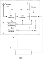
- Fig. 1 shows a GPS receiver suitable for operating in accordance with embodiments of the invention.
- the GPS receiver 5 comprises an antenna 10 coupled to an RF front-end 12.
- the RF front-end 12 includes circuitry for amplifying GPS signals received via the antenna 10. It also includes filtering circuits for attenuating out-of-band interference; and a mixer.
- the mixer multiplies the received signals with a local oscillator (LO) signal that is produced by a frequency synthesizer 14, to generate signals at sum and difference frequencies.
- LO local oscillator
- Frequency synthesizer 14 is driven by a high-frequency output OSC1 produced by a reference oscillator 16.
- the high-frequency output OSC1 of the reference oscillator 16 operates at a frequency of 26 MHz.
- the mixing operation in the RF front-end 12 yields an intermediate frequency (IF) signal that is input to analogue-to-digital (A/D) converter 18.
- IF intermediate frequency
- A/D analogue-to-digital
- the signal samples generated by the A/D converter 18 are output to processor 20 for processing.
- Both A/D converter 18 and processor 20 are clocked by a high-speed clock output CLK generated by the frequency synthesizer 14.
- CLK high-speed clock output generated by the frequency synthesizer 14.
- the analogue circuits of the RF front-end 12 and the A/D converter 18 may be of conventional types, such as will be well known to the skilled person.
- the processor 20 provides two modes for processing the signal samples received from the A/D converter 18.
- the processor operates to process the samples immediately as the signals are received and sampled. This processing comprises deriving pseudo-ranges and calculating a position fix. This mode is therefore suitable for real-time navigation, since a live position fix is provided.
- the processor is instead operable to store data in a memory 22 without completing the processing.
- the data stored in the memory 22 comprises the raw samples of IF signals provided by the A/D converter 18. However, in other embodiments it may comprise partially processed data, such as pseudo-ranges or other ranging measurements.
- a real-time clock (RTC) 24 is also provided to keep track of the current time and can be used to produce time-stamps which are associated with the data stored in the memory 22. This allows later determination of the approximate time at which the data was stored.
- RTC 24 is driven by a second output OSC2 produced by the reference oscillator 16.
- a frequency divider is used within the reference oscillator 16 to provide the low-frequency output OSC2.
- the reference oscillator 16 acts as a master oscillator generating a master clock signal from a single quartz crystal, to which both the frequency synthesizer 14 and the RTC 24 are synchronised.
- the low-frequency output OSC2 of the reference oscillator 16 operates at a frequency of approximately 26 kHz, which implies a frequency divider ratio of around one thousand.
- processor 20 may be implemented as a bespoke hardware device, such as one or more application specific integrated circuits (ASICs).
- the processor 20 may comprise one or more general purpose processing units or digital signal processors (DSPs) which have been suitably programmed. Implementation of either alternative will be well within the capabilities of those skilled in the art.
- the GPS receiver 5 is connectable to a personal computer 30 via a communications link.
- This link may be wired (for example, USB) or wireless (for example, Bluetooth or WLAN).
- part of the processing of satellite signals may be performed at the personal computer. This will be explained in greater detail in the examples below.
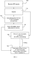
- the GPS receiver 5 receives GPS signals. These signals are digitised 110 in real-time by the A/D converter 18 to generate GPS signal samples.
- the processor operating in the first mode, processes 120 a first set of samples in real-time, to calculate a position fix. Information about this calculation is stored 130 in the memory 22.
- the receiver 5 then switches to the second mode.
- a second set of samples is stored 140 in the memory 22, for later, offline processing.
- the processor 20 in addition to its first and second modes, has a third mode. In this mode, it is adapted to retrieve the stored second set of samples from the memory 22. The processor also retrieves from the memory 22 the stored information about the calculation of the first position fix. The processor 20 processes 150 the retrieved set of samples to calculate a second position fix. This processing 150 is assisted by the information associated with the calculation of the first position fix, which has also been retrieved from the memory. The assisted processing and the information which supports it will be described in greater detail below.
- the processor enters the third mode at some time after the second mode.
- the processor enters the third mode at some time after the second mode.
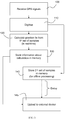
- a second embodiment of the invention will now be described, with reference to Fig. 3 .
- This embodiment is similar to the first, and the initial steps are the same.
- the second embodiment differs in that, instead of performing processing step 150, the receiver uploads 145 the stored second set of samples and stored information relating to the calculation of the first position fix to an external computing device 30. The processing of the second set of samples to calculate a second position fix will then be performed by the external device 30.
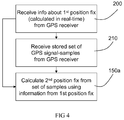
- step 200 the device 30 receives information relating to the calculation of the first position fix from the GPS receiver 5.
- step 210 the (second) set of GPS signal samples that were stored earlier by the receiver 5.
- step 150a the external device 30 processes the uploaded set of GPS signal samples to calculate a second position fix. This processing 150a exploits the information about the first position fix to assist the calculation of the second position fix.
- the information about the first position fix that is used in the calculation of the second position fix can be of a variety of types. Likewise, the way that this information assists the processing can vary. Some examples will now be described.
- the information about the first position fix comprises knowledge of the first position itself - that is, the coordinates of the first position calculated in real-time.
- This position can be used to estimate the second position. Having an initial estimate of position allows the likely visible satellites (known as "Space Vehicles", SVs) to be predicted. Consequently, in the despreading process, the searching can be made more efficient. For example, it can be assumed that the same set of SVs will be visible (that is, detectable in the second set of signal samples); thus, the correlation operation can prioritise the PN codes for these SVs.
- satellite trajectory data (such as ephemeris) can be used to determine the satellites that would have been visible from the first position, at the time that the first set of signal samples was generated.
- the time of the first position fix should also be known (or estimated).
- a similar result can be achieved by explicitly storing the list of satellites detected in the first set of signal samples. In this way, even without knowing the time of the first position fix, the list can be used to guide the correlation-search.
- the information about the first position fix comprises a time stamp of the first position fix - that is, a record of the time at which the first set of signal samples was generated. This may be used together with a time-stamp of the second set of samples; or an elapsed time (time-difference) measured between the capture of the first and second sets of samples.
- the precise (satellite-clock) time corresponding to the first position will be determined. Once determined, it is not a significant additional burden to store this information in the memory 22. If the time of capture of the second set of signal samples is also recorded, a time difference can be calculated. Alternatively, the length of time that has elapsed since the first position fix can be measured directly when the second set of samples is captured.
- WO 2009/000842 has previously disclosed how the relative timings of separately captured sets of IF data samples can be used to boost efficiency when processing all the sets together. This can also be applied to the relative timing of the first (real-time) position fix and the second (stored) set of samples.
- the satellite-clock time (Coordinated Universal Time, UTC) of the second set of samples can be predicted. This, in turn, allows a variety of parameters to be predicted which are helpful in the calculation of the second postion fix:
- the second set of samples can be annotated with a simple elapsed time counter rather than a full date/time, because the absolute UTC date/time can be deduced from the first, real-time fix.
- the receiver could count the number of periods of the carrier wave from one or more satellites between the first and second sets of samples.
- carrier-phase navigation which is known to those skilled in the art. Greater accuracy may be possible by counting half-periods - for example, by counting both rising and falling edges.
- the information associated with the first position fix comprises satellite trajectory data.
- the receiver 5 In order to calculate the first position fix, the receiver 5 must have had access to satellite ephemeris data. This may have been decoded from the satellite data messages, or downloaded from another source - as in an Assisted GPS (A-GPS) system. Rather than derive ephemeris information a second time, the ephemerides obtained by the real-time operation can be reused. If the ephemerides are within their normal period of validity, they may be used directly. If they are outside their normal period of validity, orbit prediction techniques can be used to extrapolate SV movements into the past or future. Such techniques use a celestial mechanical model to predict the dynamics of the satellites.
- the use of position can beneficially be combined with the use of time (as in the second example) to provide better assistance.
- a locus of possible positions of the device can be estimated.
- Knowledge of speed and direction of travel can be used to estimate the position at the time that the second set of samples was generated.
- speed of travel cannot be measured, a speed could be assumed based on knowledge of the application for which the GPS receiver is intended.
- the GPS receiver is designed as a bicycle accessory, then one set of assumptions can be made; if the GPS receiver is designed as an in-car navigation device (or is a Portable Navigation Device that is being powered by a cigarette lighter socket in a car) then a higher speed may be assumed. The better the approximate estimate of time and position, the greater the likely efficiency improvement when processing of the second set of samples.
- the information can be used to choose the starting-point and search-range for the code-phase search more accurately, for example.
- the aiding can be both forwards in time (using a previous real-time position fix) and backwards in time (using a subsequent real-time position fix). Furthermore, in many cases, the aiding can be achieved even more accurately and effectively by interpolating between real-time data either side of the stored samples in question, rather than simply extrapolating from a single observation.
- interpolation means that a third set of samples has been generated and processed to calculate a third position fix in real-time.
- a first position fix resulting from real-time processing of a first set of samples
- a third position fix resulting from real-time processing of a third set of samples.
- one of the first and third fixes should be earlier in time than the second set of samples, with the other of the first and third fixes being later in time.
- prediction from two position fixes is also useful if both are earlier in time than the second set of samples, or if both are later in time. Nevertheless, for simplicity in the following examples, we will refer to "interpolation" in the sense of one real-time fix to each side (on the time axis) of the second set of samples.
- the limit of clock error (for example) for the second set of samples might be expressed as: ClkErrR + / ⁇ MaxClkErrRate * TC ⁇ TR (where ClkErrR is the clock error measured at the real-time fix at time TR, the capture was recorded at time TC and MaxClkErrRate is the maximum rate of change of clock error - usually defined by the specification of the crystal oscillator part used in the reference oscillator 16 of the receiver and measured in parts per million.)
- each of these refinements is to reduce the search range for code-phase during despreading (in many cases quite substantially), as well as providing a better centre value (that is, initial estimate). This is likely to improve success rates as well as reducing computational cost.
- the interpolation may also include terms for measurement error - for example the measured clock errors ClkErrR1 and ClkErrR2, above, may be uncertain.
- the rate at which uncertainty grows may also be modelled in a more sophisticated (for example non-linear) manner. It may also be desirable to incorporate knowledge (from the real-time fixes) of receiver velocity and clock drift (that is, the rate of change of clock error).
- the embodiments described above depend on the GPS receiver 5 being in the first mode (real-time positioning) for some of the time and the second mode (Capture-and-Process) at other times. This may depend on the usage of the device: for example, real-time activity may be initiated by the user when he/she needs to use real-time navigation functions. Alternatively, it may be helpful for the receiver 4 to periodically enter the first mode and perform at least one real-time position fix, deliberately for the purpose of aiding subsequent offline processing of intervening, stored sets of signal samples. This could ensure, for example, that some ephemeris is downloaded every few hours (or even days if using orbital prediction to extend the period of validity), or that a position fix is attempted occasionally.
- a second set of samples is stored in a "raw" form - in particular, as sampled intermediate frequency (IF) signals. That is, the samples are stored directly after digitisation, without further processing.
- the second set of samples may be processed in real-time to derive intermediate data, such as ranging measurements. These ranging measurements may then be stored.
- intermediate data such as ranging measurements.
- the information associated with the first (real-time) position fix that is used to aid the calculation of the second position fix would typically be satellite trajectory data, such as ephemeris, along with time-stamps or time-differences, as described earlier above.
- the stored ranging measurements comprise pseudoranges
- the stored satellite trajectory information relating to the first position fix can be used (together with knowledge of the relative times) to calculate a position fix.
- WO 2009/000842 discloses how a complete copy of the data messages transmitted by all satellites can be used to allow pseudo-ranges and position fixes to be calculated from captures (sets of samples) of shorter duration than would otherwise be possible.
- D-GPS Differential GPS
- DGPS Differential GPS
- One common way of applying the corrections is to correct the ranging measurements made from the received GPS signals. This is because a significant source of positioning error is due to ionospheric and tropospheric distortions. These result in errors in the ranging measurements because they distort the relationship between time-of-flight of the radio waves and the distance travelled. These errors are relatively stable over moderate periods of time and distances. Therefore, if the receiver 5 uses DGPS corrections in its real-time position calculations, it may be advantageous for the corrections to be stored in the memory 22.
- the same corrections can then be applied when the second set of signal samples (or ranging measurements derived from the samples) are processed to calculate the second position fix.
- the corrections will be helpful to the extent that the receiver is in approximately the same area and the atmospheric propagation conditions have not changed significantly.
- the receiver may store code-phases. This avoids the additional processing needed to establish the coarse timing (position in the data message). However, in this case, supplementary information will be needed when the code-phases are later processed, to allow the coarse timing ambiguity to be resolved. Typically, therefore, some other information will need to be stored along with the code-phases or obtained separately.
- the coarse timing can be determined in a wide variety of ways, and so the type of data which should be stored to augment the code-phases can also vary widely. Ultimately, what is needed is an approximate estimate of the time-instant to which the code-phase measurement corresponds and some way to relate this estimate to the satellite clock. This then enables the position in the data message to be determined. Approximate times could be determined from an internal real-time clock of the receiver, provided the relationship between this real-time clock and the satellite clock can be established accurately enough to resolve the ambiguity. Thus, in one example, time-stamps generated by the internal real-time clock can be stored to supplement measured code-phases.
- the relationship with the satellite clock could be established by intermittently storing a block of signal samples that is long enough to extract satellite clock information (also with a local time-stamp).
- Alternative ways of determining the coarse timing will be apparent to those skilled in the art. For example, it would be possible to use a coarse estimate of position (at the time the code-phases were measured) to extrapolate the coarse timing (because the timing is uniquely related to the relative positions of the satellites with respect to the receiver at every time instant).
- a coarse position estimate might be available from some external source, or could, for example, be calculated from the observed Doppler shifts of the satellite constellation. In this way, storing the apparent (observed) satellite broadcast frequencies could also be a suitable supplement for stored code-phases.
- WO 2006/018803 describes one efficient and effective way of storing time-stamps together with signal samples: a small portion of the GPS signal samples can simply be overwritten (replaced) in the memory by the time-stamp bits. This not only avoids the need for separate records of time-stamp but also ensures accurate synchronisation of the time-stamp against the received samples. The small, missing part of the captured set of samples does not usually degrade the subsequent processing steps.
- the receiver 5 may be an assisted GPS (A-GPS) receiver, which can obtain almanac; ephemeris; or potentially full satellite data-message records from an assistance server.
- the server may gather this information from a fixed GPS receiver or a network of receivers dispersed around the world. Each of these reference receivers reports decoded satellite data messages to the central database. Alternatively, the aiding data could be gathered dynamically from a network of mobile GPS receivers. That is, each GPS receiver would share its own, fragmentary observations of satellite data messages with the central server. The server would aggregate these observations to form a complete record, which could then be accessed by all receivers.
- communication with a data-aiding server can be by any convenient means, but will usually be via a wireless data connection of some kind.
- Nominally stale satellite trajectory data may be enhanced by using more advanced techniques to extrapolate the orbits of the satellites. For example, models of the movement, interaction and gravitational influence of celestial bodies (like the earth, sun and moon) may be used generate better estimates of satellite trajectory. This can allow ephemeris and almanac information to be used far outside (either before or after) the normal period of validity.
- the mode in which the receiver 5 operates may be selected based on the availability of valid satellite trajectory data (for example, ephemeris). In other embodiments, the selection of operation mode may be based on other indicators. For example, the receiver 5 may process samples in real-time (the first mode) when the device is connected to an external power supply. This means that the energy-intensive processing needed for live position-calculation is only engaged when an external power source is present. When the device is running on internal battery power, it operates in the second mode (storing samples or pseudo-ranges, without calculating position fixes) to extend battery life.
- detection of an external power supply can also be used to trigger the processing of data that has been stored in the memory (while the device was operating in the second mode). That is, in response to connection to an external power supply the receiver may enter the third mode.
- the processing functions of the third mode may be performed in parallel with those of the first and second modes. That is, the first and third modes, and the second and third modes, are not mutual exclusive.
- Fig. 1 shows a receiver in which both the real-time clock (RTC) 24 and the frequency synthesizer 14 derive their clock signals from the same source - that is, a master reference oscillator 16 operating from a single crystal.
- RTC real-time clock
- the RTC 24 may be driven by a separate, slower-running RTC oscillator using its own crystal, for instance a 32.768 kHz RTC crystal.
- the clock signal driving the RTC can be independent from that driving the frequency synthesizer 14.
- the present invention is not limited to the calculation of position estimates.
- Other parameters such as velocity may of course be calculated in addition.
- velocity may of course be calculated in addition.
- it is well known to calculate velocity from the Doppler shifts of satellite positioning signals, once the position of a receiver is known.
- further filtering of the received GPS signals may be performed after the signals have been sampled.
- US 2008/0240315 describes methods and circuits for interference suppression.
- the filtering can be part of the RF front-end or part of the base-band processing.
- Digital filtering of this kind may be adaptive. That is, the sampled signals may be analysed to determine if interference is present and, if so, to measure the properties of the interference (for example, frequency or power). The digital filtering can then be adapted automatically to cancel or attenuate the interference optimally.
- bit-width that is, bit-resolution
- decimation and/or bit-resolution reduction can reduce power consumption and/or complexity of the processing hardware.
- the quality of the resulting reduced-resolution signals is likely to be greater.
- references to "sampling" received signals and "storing" resultant signal samples should therefore be taken to include the possibility of additional filtering between the sampling step (analogue-to-digital conversion) and the step of storing the samples.
- a computer program may be stored/distributed on a suitable medium, such as an optical storage medium or a solid-state medium supplied together with or as part of other hardware, but may also be distributed in other forms, such as via the Internet or other wired or wireless telecommunication systems. Any reference signs in the claims should not be construed as limiting the scope.
- GNSS Global Navigation Satellite Systems
- GLONASS Russian Global Navigation Satellite System
- Galileo European project
- Pseudolites are typically terrestrial transmitters which broadcast a signal that is analogous (or identical) to the signals transmitted by GPS satellites.
- a pseudolite may use the same L1 frequency used by the GPS satellites, and a similar spread-spectrum modulation scheme.
- pseudolite signals can be processed in the same way as satellite positioning signals, the present specification should be taken as disclosing equivalent techniques for calculating a second position fix from pseudolite signals, assisted by reference information associated with the calculation of a first position fix.
Landscapes
- Engineering & Computer Science (AREA)
- Radar, Positioning & Navigation (AREA)
- Remote Sensing (AREA)
- Physics & Mathematics (AREA)
- General Physics & Mathematics (AREA)
- Computer Networks & Wireless Communication (AREA)
- Power Engineering (AREA)
- Position Fixing By Use Of Radio Waves (AREA)
Claims (14)
- Un récepteur de positionnement par satellites (5), comprenant :une tête RF (12) pour la réception de signaux de positionnement par satellite ;un convertisseur analogique-numérique (18) assurant l'échantillonnage des signaux reçus pour la génération d'échantillons de signaux ;une mémoire (22) ; etun processeur (20) pour le traitement d'échantillons de signaux, pour dériver des mesures télémétriques, et calculer un point fixe,le récepteur (5) possédant un premier mode dans lequel le processeur (20) est utilisable :pour le traitement d'un premier ensemble des échantillons au fur et à mesure qu'ils sont générés, pour le calcul d'un premier point fixe ;pour la mise en mémoire (22) d'informations concernant ce calcul ;pour le traitement d'un troisième ensemble d'échantillons au fur et à mesure qu'ils sont générés, pour le calcul d'un troisième point fixe ; etpour la mise en mémoire (22) d'informations concernant ce calcul,le récepteur (5) possédant un deuxième mode dans lequel il peut être utilisé pour la mise en mémoire (22) d'un deuxième ensemble d'échantillons, ou de mesures télémétriques dérivées du deuxième ensemble d'échantillons, pour leur traitement ultérieur pour le calcul d'un deuxième point fixe ; etle récepteur possédant un troisième mode dans lequel le processeur (20) est utilisable :pour récupérer de la mémoire (22) le deuxième ensemble d'échantillons ou de mesures télémétriques mis en mémoire ; etpour leur traitement afin de calculer le deuxième point fixe,ledit traitement étant assisté par les informations relatives au calcul du premier point fixe et les informations relatives au calcul du troisième point fixe.
- Le récepteur selon la revendication 1, les informations relatives au calcul du premier point fixe, utilisées pour faciliter le calcul du deuxième point fixe, comprenant une ou plusieurs des suivantes :la première position ;une vitesse relative à la première position ;une heure à laquelle le premier ensemble d'échantillons a été reçu ;une liste d'un ou plusieurs satellites dont les signaux ont été détectés dans le premier ensemble d'échantillons ;une fréquence de porteuse détectée de ce satellite ;un décalage Doppler détecté de cette fréquence de porteuse ;une mesure télémétrique dérivée du premier ensemble d'échantillons ;une correction différentielle appliquée à cette mesure télémétrique ;des données éphémérides utilisées dans le calcul du premier point fixe ;une portion d'un message de données transmis par un satellite ;des informations sur la santé du satellite ;des données sur des corrections des horloges de satellites ; etun paramètre d'incertitude relatif à une quelconque des informations précédentes.
- Le récepteur selon la revendication 1 ou la revendication 2, le récepteur (5) étant adapté pour la mise en mémoire (22) d'un horodatage se rapportant à la réception du premier ensemble d'échantillons, du deuxième ensemble d'échantillons, ou des deux.
- Le récepteur (5) selon une quelconque des revendications 1 à 3, le processeur étant adapté pour mesurer un temps écoulé entre la réception du premier ensemble d'échantillons et la réception du deuxième ensemble d'échantillons.
- Le récepteur selon une quelconque des revendications précédentes, le calcul du deuxième point fixe étant assisté par une des suivantes, ou les deux :la prédiction de données éphémérides appropriées pour le calcul du deuxième point fixe, basées sur des données éphémérides utilisées pour le calcul du premier point fixe ; etla prédiction d'une phase de code du code d'étalement pour un ou plusieurs satellites dans le deuxième ensemble d'échantillons de signaux, basée sur au moins une phase de code déterminée dans le processus du calcul du premier point fixe.
- Le récepteur selon une quelconque des revendications précédentes, le calcul du deuxième point fixe étant assisté par la prédiction linéaire ou non linéaire de la valeur d'au moins un paramètre, sur la base de valeurs de ce paramètre relatives aux première et troisième positions.
- Le récepteur selon une quelconque des revendications précédentes, adapté également pour entrer le premier mode périodiquement.
- Un récepteur de positionnement par satellites (5), comprenant :une tête RF (12) pour la réception de signaux de positionnement par satellite ;un convertisseur analogique-numérique (18) assurant l'échantillonnage des signaux reçus pour la génération d'échantillons de signaux ;une mémoire (22) ; etun processeur (20) pour le traitement d'échantillons de signaux, pour dériver des mesures télémétriques, et pour calculer un point fixe,le récepteur (5) possédant un premier mode dans lequel le processeur (20) est utilisable :pour le traitement d'un premier ensemble des échantillons au fur et à mesure qu'ils sont générés, pour le calcul d'un premier point fixe ;pour la mise en mémoire (22) d'informations concernant ce calcul ;pour le traitement d'un troisième ensemble d'échantillons au fur et à mesure qu'ils sont générés, pour le calcul d'un troisième point fixe ; etpour la mise en mémoire (22) d'informations concernant ce calcul,le récepteur (5) possédant un deuxième mode dans lequel il peut être utilisé pour la mise en mémoire (22) d'un deuxième ensemble d'échantillons, ou de mesures télémétriques dérivées du deuxième ensemble d'échantillons, pour leur traitement ultérieur pour le calcul d'un deuxième point fixe,le récepteur étant adapté pour télécharger les informations et le deuxième ensemble d'échantillons, ou de mesures télémétriques, mis en mémoire (22) dans un dispositif extérieur (30), par lequel le deuxième ensemble d'échantillons, ou de mesures télémétriques, peut être traité pour le calcul du deuxième point fixe, ledit traitement étant assisté par les informations relatives au calcul du premier point fixe et les informations relatives au calcul du troisième point fixe.
- Le récepteur selon la revendication 8, le récepteur étant adapté :pour la mise en mémoire (22)d'un horodatage relatif à la réception du premier ensemble d'échantillons, du deuxième ensemble d'échantillons, ou des deux ; etpour télécharger ledit horodatage ou lesdits horodatages dans le dispositif extérieur.
- Le récepteur selon la revendication 8 ou la revendication 9, le processeur étant adapté pour mesurer un temps écoulé entre la réception du premier ensemble d'échantillons et la réception du deuxième ensemble d'échantillons.
- Une méthode de calcul d'un point fixe d'après des échantillons de signaux de satellites mis en mémoire précédemment, cette méthode comprenant :la réception (200, 210), d'un récepteur de positionnement par satellites :(200) d'informations concernant le calcul d'un premier point fixe calculé par le récepteur provenant d'un premier ensemble d'échantillons de signaux de satellites ;d'informations concernant le calcul d'un troisième point fixe calculé par le récepteur provenant d'un troisième ensemble d'échantillons de signaux de satellites ; et
(210) d'un deuxième ensemble d'échantillons de signaux de satellites, ou de mesures télémétriques dérivées d'un deuxième ensemble d'échantillons de signaux de satellites, etle traitement (150a) du deuxième ensemble d'échantillons ou de mesures télémétriques pour calculer un deuxième point fixe,ledit traitement étant assisté par les informations concernant le calcul du premier point fixe, et les informations relatives au calcul du troisième point fixe. - La méthode selon la revendication 11, les informations relatives au calcul du premier point fixe, utilisées pour faciliter le calcul du deuxième point fixe, comprenant des connaissances sur une ou plusieurs des suivantes :la première position ;une vitesse relative à la première position ;une heure à laquelle le premier ensemble d'échantillons a été reçu ;une liste d'un ou plusieurs satellites dont les signaux ont été détectés dans le premier ensemble d'échantillons ;une fréquence de porteuse détectée de ce satellite ;un décalage Doppler détecté de cette fréquence de porteuse ;une mesure télémétrique dérivée du premier ensemble d'échantillons ;une correction différentielle appliquée à cette mesure télémétrique ;des données éphémérides utilisées dans le calcul du premier point fixe ;une portion d'un message de données transmis par un satellite ;des informations sur la santé du satellite ;des données sur des corrections des horloges de satellite.
- Une méthode de calcul de trois point fixes, faisant usage du positionnement par satellite, cette méthode comprenant :l'utilisation d'une tête RF recevant (100) des signaux de positionnement par satellite ;l'utilisation d'un convertisseur analogique-numérique assurant l'échantillonnage (110) des signaux reçus pour la génération d'échantillons de signaux ;l'utilisation d'un processeur pour le traitement (120) d'un premier ensemble d'échantillons au fur et à mesure qu'ils sont générés, pour le calcul d'un premier point fixe ;la mise en mémoire (130) d'informations concernant le calcul d'informations dans une mémoire ;
(22) l'utilisation du processeur, assurant le traitement (120) d'un troisième ensemble d'échantillons au fur et à mesure qu'ils sont générés, pour le calcul d'un troisième point fixe ;la mise en mémoire (130) d'informations concernant ce calcul dans la mémoire ;la mise en mémoire (140) d'un deuxième ensemble d'échantillons, ou de mesures télémétriques, dérivés du deuxième ensemble d'échantillons d'informations, dans la mémoire (22)pour un traitement ultérieur pour calculer un deuxième point fixe ;etle traitement (150, 150a), ultérieurement, du deuxième ensemble d'échantillons pour le calcul du deuxième point fixe, le calcul du deuxième point fixe étant assisté par les informations concernant le calcul du premier point fixe et les informations relatives au calcul du troisième point fixe. - Un programme informatique comprenant un moyen de code de programme informatique adapté pour l'exécution de toutes les étapes d'une quelconque des revendications 11 à 13, lorsque ledit programme est exécuté sur un ordinateur.
Priority Applications (4)
| Application Number | Priority Date | Filing Date | Title |
|---|---|---|---|
| EP11168462.7A EP2530488B1 (fr) | 2011-06-01 | 2011-06-01 | Positionnement de satellite hybride avec prédiction |
| US13/160,424 US8614641B2 (en) | 2011-06-01 | 2011-06-14 | Hybrid satellite positioning with prediction |
| CN2012101791326A CN102809750A (zh) | 2011-06-01 | 2012-05-30 | 利用预测的混合式卫星定位 |
| JP2012124109A JP2012255778A (ja) | 2011-06-01 | 2012-05-31 | 予測を伴うハイブリッド衛星測位 |
Applications Claiming Priority (1)
| Application Number | Priority Date | Filing Date | Title |
|---|---|---|---|
| EP11168462.7A EP2530488B1 (fr) | 2011-06-01 | 2011-06-01 | Positionnement de satellite hybride avec prédiction |
Publications (2)
| Publication Number | Publication Date |
|---|---|
| EP2530488A1 EP2530488A1 (fr) | 2012-12-05 |
| EP2530488B1 true EP2530488B1 (fr) | 2016-04-13 |
Family
ID=44801252
Family Applications (1)
| Application Number | Title | Priority Date | Filing Date |
|---|---|---|---|
| EP11168462.7A Active EP2530488B1 (fr) | 2011-06-01 | 2011-06-01 | Positionnement de satellite hybride avec prédiction |
Country Status (4)
| Country | Link |
|---|---|
| US (1) | US8614641B2 (fr) |
| EP (1) | EP2530488B1 (fr) |
| JP (1) | JP2012255778A (fr) |
| CN (1) | CN102809750A (fr) |
Families Citing this family (25)
| Publication number | Priority date | Publication date | Assignee | Title |
|---|---|---|---|---|
| JP5425478B2 (ja) * | 2006-03-06 | 2014-02-26 | クゥアルコム・インコーポレイテッド | 測量スティッチングを用いる位置測定方法 |
| US9074897B2 (en) * | 2009-06-15 | 2015-07-07 | Qualcomm Incorporated | Real-time data with post-processing |
| US8704707B2 (en) * | 2010-06-02 | 2014-04-22 | Qualcomm Incorporated | Position determination using measurements from past and present epochs |
| JP5742450B2 (ja) * | 2011-05-10 | 2015-07-01 | セイコーエプソン株式会社 | 位置算出方法及び位置算出装置 |
| EP2530487B1 (fr) * | 2011-06-01 | 2014-10-01 | u-blox A.G. | Positionnement de satellite avec calcul assisté |
| EP2674784A1 (fr) * | 2012-06-11 | 2013-12-18 | U-blox AG | Positionnement par satellite avec paramètres de capture mélangés |
| US9521508B2 (en) | 2013-06-19 | 2016-12-13 | Blackberry Limited | Architecture and method to 4G-mobile positioning |
| US9507010B2 (en) | 2013-12-20 | 2016-11-29 | Blackberry Limited | Method for improving clock accuracy in a wide area positioning pseudolite receiver system architecture |
| US10809365B2 (en) * | 2014-08-25 | 2020-10-20 | Texas Instruments Incorporated | Vibration parameters monitoring using FMCW radar |
| US10185035B2 (en) * | 2014-12-30 | 2019-01-22 | Mediatek Inc. | Satellite-based positioning method and associated apparatus |
| CN105826686A (zh) * | 2015-01-08 | 2016-08-03 | 万旭电业股份有限公司 | 双极化阵列天线的增益方法及其结构 |
| CN111337936A (zh) * | 2015-01-20 | 2020-06-26 | 托里派因斯洛基股份有限责任公司 | 单孔激光测距仪 |
| WO2017082304A1 (fr) * | 2015-11-11 | 2017-05-18 | 日本電気株式会社 | Dispositif de compression d'informations, procédé de compression d'informations, support d'enregistrement et dispositif de codage |
| JP2017173067A (ja) * | 2016-03-23 | 2017-09-28 | カシオ計算機株式会社 | 測位装置、測位方法及びプログラム |
| US10845487B2 (en) * | 2017-06-13 | 2020-11-24 | Microsoft Technology Licensing, Llc | Acquisition in global navigation satellite systems based on previously acquired satellites |
| EP3518003B1 (fr) * | 2018-01-25 | 2021-03-24 | Centre National d'Etudes Spatiales | Acquisition rapide auto-assistée et premier positionnement pour un récepteur gnss autonome |
| DE102018222320A1 (de) * | 2018-12-19 | 2020-06-25 | Robert Bosch Gmbh | Objekterkennungsvorrichtung für Fahrzeuge und Verfahren zur Erkennung eines Objektes für Fahrzeuge |
| JP2020169858A (ja) * | 2019-04-02 | 2020-10-15 | 富士通株式会社 | 位置検知システム、位置検知装置および位置検知方法 |
| US11711202B2 (en) | 2019-05-29 | 2023-07-25 | International Business Machines Corporation | Committing data to blockchain based on approximate hash verification |
| US11429738B2 (en) | 2019-05-29 | 2022-08-30 | International Business Machines Corporation | Blockchain endorsement with approximate hash verification |
| US11570002B2 (en) | 2019-05-29 | 2023-01-31 | International Business Machines Corporation | Reduced-step blockchain verification of media file |
| US11516000B2 (en) | 2019-05-29 | 2022-11-29 | International Business Machines Corporation | Approximate hash verification of unused blockchain output |
| US11539527B2 (en) | 2019-05-29 | 2022-12-27 | International Business Machines Corporation | Peer node recovery via approximate hash verification |
| EP4113172A1 (fr) * | 2021-07-01 | 2023-01-04 | u-blox AG | Procédé pour effectuer une recherche parallèle, récepteur, produit-programme informatique et support de stockage non volatile |
| CN113687392B (zh) * | 2021-08-23 | 2024-04-12 | 深圳乐心信息技术有限公司 | 一种基于gnss信号非连续跟踪的导航方法 |
Family Cites Families (27)
| Publication number | Priority date | Publication date | Assignee | Title |
|---|---|---|---|---|
| US5515043A (en) | 1994-08-17 | 1996-05-07 | Berard; Alfredo J. | Cellular/GPS system for vehicle tracking |
| DE69638262D1 (de) * | 1995-10-09 | 2010-10-28 | Snaptrack Inc | GPS-Empfänger und Verfahren zur Verarbeitung von GPS-Signalen |
| US6133871A (en) | 1995-10-09 | 2000-10-17 | Snaptrack, Inc. | GPS receiver having power management |
| US6295024B1 (en) | 1999-02-19 | 2001-09-25 | Motorola, Inc. | Autonomous data aided GPS signal acquisition method and system |
| GB0004371D0 (en) | 2000-02-24 | 2000-04-12 | Koninkl Philips Electronics Nv | GPS receiver and mobile unit incorporating the same |
| US7970412B2 (en) | 2000-05-18 | 2011-06-28 | Sirf Technology, Inc. | Aided location communication system |
| GB0308054D0 (en) | 2003-04-08 | 2003-05-14 | Koninkl Philips Electronics Nv | A method of position stamping a photo or video clip taken with a digital camera |
| CN103792555B (zh) * | 2003-04-25 | 2017-01-04 | 高通股份有限公司 | 获得信号捕获辅助数据的系统和方法 |
| WO2005072458A2 (fr) | 2004-01-28 | 2005-08-11 | Delorme Publishing Company, Inc. | Procede et dispositif de traitement de donnees gps brutes |
| GB0418357D0 (en) | 2004-08-18 | 2004-09-22 | Koninkl Philips Electronics Nv | Gps receiver and related method and apparatus |
| JP4356688B2 (ja) | 2005-12-07 | 2009-11-04 | ソニー株式会社 | 撮像装置、およびデータ記録方法、データ表示制御方法、並びにコンピュータ・プログラム |
| US8606299B2 (en) | 2006-01-09 | 2013-12-10 | Qualcomm Incorporated | Apparatus and methods for geographic position approximation of an event occurring on a wireless device |
| EP1989871A1 (fr) | 2006-02-23 | 2008-11-12 | Geotate B.V. | Procede de creation de fichier d'image et appareil photo numerique l'utilisant |
| US7982667B2 (en) | 2006-04-17 | 2011-07-19 | Trimble Navigation Limited | Post-processed accuracy prediction for GNSS positioning |
| US8063818B2 (en) | 2006-11-08 | 2011-11-22 | The Johns Hopkins University | Cross-PRN phase correction for GPS processing |
| US7564406B2 (en) | 2006-11-10 | 2009-07-21 | Sirf Technology, Inc. | Method and apparatus in standalone positioning without broadcast ephemeris |
| DE602007006417D1 (de) | 2007-03-26 | 2010-06-24 | Blox A G U | Verfahren zur Bearbeitung eines von einem analogen Eingangssignal eines GNSS-Empfängers abgeleiteten digitalen Signals, Basisbandschaltung eines GNSS-Empfängers zur Durchführung des Verfahrens und GNSS-Empfänger |
| US7835863B2 (en) | 2007-04-18 | 2010-11-16 | Mitac International Corporation | Method and system for navigation using GPS velocity vector |
| CN101711368B (zh) | 2007-06-26 | 2013-09-11 | 瑞士优北罗股份有限公司 | 用于对卫星定位系统信号进行处理的方法和系统 |
| WO2009065206A1 (fr) * | 2007-11-19 | 2009-05-28 | Rx Networks Inc. | Modélisation d'orbite distribuée et procédé de propagation pour un système gps assisté prédit et en temps réel |
| GB2459500A (en) * | 2008-04-25 | 2009-10-28 | Geotate Bv | Triggered satellite positioning system |
| US7659848B2 (en) | 2008-04-29 | 2010-02-09 | Geotate B.V. | Event location determination |
| GB2463481A (en) * | 2008-09-12 | 2010-03-17 | Geotate Bv | Means for estimating the location of an event using a satellite positioning system |
| US9014727B2 (en) * | 2009-02-27 | 2015-04-21 | Broadcom Corporation | Method and system for updating obsolete records for reference positions in a reference position database |
| US8164518B2 (en) | 2009-06-19 | 2012-04-24 | Broadcom Corporation | Method and system for a GNSS receiver with self-assisted ephemeris extensions |
| US8217832B2 (en) * | 2009-09-23 | 2012-07-10 | Andrew, Llc | Enhancing location accuracy using multiple satellite measurements based on environment |
| EP2339378B1 (fr) * | 2009-12-17 | 2013-03-20 | u-blox AG | Récepteur de positionnement de satellite hybride |
-
2011
- 2011-06-01 EP EP11168462.7A patent/EP2530488B1/fr active Active
- 2011-06-14 US US13/160,424 patent/US8614641B2/en active Active
-
2012
- 2012-05-30 CN CN2012101791326A patent/CN102809750A/zh active Pending
- 2012-05-31 JP JP2012124109A patent/JP2012255778A/ja not_active Withdrawn
Also Published As
| Publication number | Publication date |
|---|---|
| US8614641B2 (en) | 2013-12-24 |
| US20120306689A1 (en) | 2012-12-06 |
| JP2012255778A (ja) | 2012-12-27 |
| EP2530488A1 (fr) | 2012-12-05 |
| CN102809750A (zh) | 2012-12-05 |
Similar Documents
| Publication | Publication Date | Title |
|---|---|---|
| EP2530488B1 (fr) | Positionnement de satellite hybride avec prédiction | |
| EP2530487B1 (fr) | Positionnement de satellite avec calcul assisté | |
| EP1891456B1 (fr) | Soutien de localisation par satellite assistee | |
| US7701387B2 (en) | Supporting an assisted satellite based positioning | |
| EP2339378B1 (fr) | Récepteur de positionnement de satellite hybride | |
| US20120293366A1 (en) | System, method and computer program for ultra fast time to first fix for a gnss receiver | |
| US20070159387A1 (en) | Supporting an assisted satellite based positioning | |
| EP2380034B1 (fr) | Détermination de l'emplacement d'un événement | |
| RU2394252C2 (ru) | Поддержка определения местоположения с помощью спутников | |
| RU2386142C2 (ru) | Поддержка определения местоположения с помощью спутников | |
| EP2674784A1 (fr) | Positionnement par satellite avec paramètres de capture mélangés |
Legal Events
| Date | Code | Title | Description |
|---|---|---|---|
| PUAI | Public reference made under article 153(3) epc to a published international application that has entered the european phase |
Free format text: ORIGINAL CODE: 0009012 |
|
| AK | Designated contracting states |
Kind code of ref document: A1 Designated state(s): AL AT BE BG CH CY CZ DE DK EE ES FI FR GB GR HR HU IE IS IT LI LT LU LV MC MK MT NL NO PL PT RO RS SE SI SK SM TR |
|
| AX | Request for extension of the european patent |
Extension state: BA ME |
|
| 17P | Request for examination filed |
Effective date: 20130605 |
|
| RBV | Designated contracting states (corrected) |
Designated state(s): AL AT BE BG CH CY CZ DE DK EE ES FI FR GB GR HR HU IE IS IT LI LT LU LV MC MK MT NL NO PL PT RO RS SE SI SK SM TR |
|
| 17Q | First examination report despatched |
Effective date: 20130903 |
|
| REG | Reference to a national code |
Ref country code: DE Ref legal event code: R079 Ref document number: 602011025198 Country of ref document: DE Free format text: PREVIOUS MAIN CLASS: G01S0019270000 Ipc: G01S0005000000 |
|
| GRAP | Despatch of communication of intention to grant a patent |
Free format text: ORIGINAL CODE: EPIDOSNIGR1 |
|
| RIC1 | Information provided on ipc code assigned before grant |
Ipc: G01S 19/27 20100101ALI20150925BHEP Ipc: G01S 5/00 20060101AFI20150925BHEP Ipc: G01S 19/09 20100101ALI20150925BHEP Ipc: G01S 19/23 20100101ALI20150925BHEP |
|
| INTG | Intention to grant announced |
Effective date: 20151014 |
|
| GRAS | Grant fee paid |
Free format text: ORIGINAL CODE: EPIDOSNIGR3 |
|
| GRAA | (expected) grant |
Free format text: ORIGINAL CODE: 0009210 |
|
| AK | Designated contracting states |
Kind code of ref document: B1 Designated state(s): AL AT BE BG CH CY CZ DE DK EE ES FI FR GB GR HR HU IE IS IT LI LT LU LV MC MK MT NL NO PL PT RO RS SE SI SK SM TR |
|
| REG | Reference to a national code |
Ref country code: GB Ref legal event code: FG4D |
|
| REG | Reference to a national code |
Ref country code: AT Ref legal event code: REF Ref document number: 790717 Country of ref document: AT Kind code of ref document: T Effective date: 20160415 Ref country code: CH Ref legal event code: EP |
|
| REG | Reference to a national code |
Ref country code: IE Ref legal event code: FG4D |
|
| REG | Reference to a national code |
Ref country code: DE Ref legal event code: R096 Ref document number: 602011025198 Country of ref document: DE |
|
| REG | Reference to a national code |
Ref country code: CH Ref legal event code: PLX |
|
| REG | Reference to a national code |
Ref country code: FR Ref legal event code: PLFP Year of fee payment: 6 |
|
| PG25 | Lapsed in a contracting state [announced via postgrant information from national office to epo] |
Ref country code: CH Free format text: LAPSE BECAUSE OF THE APPLICANT RENOUNCES Effective date: 20160413 Ref country code: LI Free format text: LAPSE BECAUSE OF THE APPLICANT RENOUNCES Effective date: 20160413 |
|
| REG | Reference to a national code |
Ref country code: LT Ref legal event code: MG4D |
|
| REG | Reference to a national code |
Ref country code: AT Ref legal event code: MK05 Ref document number: 790717 Country of ref document: AT Kind code of ref document: T Effective date: 20160413 |
|
| REG | Reference to a national code |
Ref country code: NL Ref legal event code: MP Effective date: 20160413 |
|
| PG25 | Lapsed in a contracting state [announced via postgrant information from national office to epo] |
Ref country code: FI Free format text: LAPSE BECAUSE OF FAILURE TO SUBMIT A TRANSLATION OF THE DESCRIPTION OR TO PAY THE FEE WITHIN THE PRESCRIBED TIME-LIMIT Effective date: 20160413 Ref country code: LT Free format text: LAPSE BECAUSE OF FAILURE TO SUBMIT A TRANSLATION OF THE DESCRIPTION OR TO PAY THE FEE WITHIN THE PRESCRIBED TIME-LIMIT Effective date: 20160413 Ref country code: NL Free format text: LAPSE BECAUSE OF FAILURE TO SUBMIT A TRANSLATION OF THE DESCRIPTION OR TO PAY THE FEE WITHIN THE PRESCRIBED TIME-LIMIT Effective date: 20160413 Ref country code: NO Free format text: LAPSE BECAUSE OF FAILURE TO SUBMIT A TRANSLATION OF THE DESCRIPTION OR TO PAY THE FEE WITHIN THE PRESCRIBED TIME-LIMIT Effective date: 20160713 Ref country code: PL Free format text: LAPSE BECAUSE OF FAILURE TO SUBMIT A TRANSLATION OF THE DESCRIPTION OR TO PAY THE FEE WITHIN THE PRESCRIBED TIME-LIMIT Effective date: 20160413 |
|
| PG25 | Lapsed in a contracting state [announced via postgrant information from national office to epo] |
Ref country code: ES Free format text: LAPSE BECAUSE OF FAILURE TO SUBMIT A TRANSLATION OF THE DESCRIPTION OR TO PAY THE FEE WITHIN THE PRESCRIBED TIME-LIMIT Effective date: 20160413 Ref country code: HR Free format text: LAPSE BECAUSE OF FAILURE TO SUBMIT A TRANSLATION OF THE DESCRIPTION OR TO PAY THE FEE WITHIN THE PRESCRIBED TIME-LIMIT Effective date: 20160413 Ref country code: RS Free format text: LAPSE BECAUSE OF FAILURE TO SUBMIT A TRANSLATION OF THE DESCRIPTION OR TO PAY THE FEE WITHIN THE PRESCRIBED TIME-LIMIT Effective date: 20160413 Ref country code: GR Free format text: LAPSE BECAUSE OF FAILURE TO SUBMIT A TRANSLATION OF THE DESCRIPTION OR TO PAY THE FEE WITHIN THE PRESCRIBED TIME-LIMIT Effective date: 20160714 Ref country code: SE Free format text: LAPSE BECAUSE OF FAILURE TO SUBMIT A TRANSLATION OF THE DESCRIPTION OR TO PAY THE FEE WITHIN THE PRESCRIBED TIME-LIMIT Effective date: 20160413 Ref country code: LV Free format text: LAPSE BECAUSE OF FAILURE TO SUBMIT A TRANSLATION OF THE DESCRIPTION OR TO PAY THE FEE WITHIN THE PRESCRIBED TIME-LIMIT Effective date: 20160413 Ref country code: PT Free format text: LAPSE BECAUSE OF FAILURE TO SUBMIT A TRANSLATION OF THE DESCRIPTION OR TO PAY THE FEE WITHIN THE PRESCRIBED TIME-LIMIT Effective date: 20160816 Ref country code: AT Free format text: LAPSE BECAUSE OF FAILURE TO SUBMIT A TRANSLATION OF THE DESCRIPTION OR TO PAY THE FEE WITHIN THE PRESCRIBED TIME-LIMIT Effective date: 20160413 |
|
| PG25 | Lapsed in a contracting state [announced via postgrant information from national office to epo] |
Ref country code: BE Free format text: LAPSE BECAUSE OF FAILURE TO SUBMIT A TRANSLATION OF THE DESCRIPTION OR TO PAY THE FEE WITHIN THE PRESCRIBED TIME-LIMIT Effective date: 20160413 Ref country code: IT Free format text: LAPSE BECAUSE OF FAILURE TO SUBMIT A TRANSLATION OF THE DESCRIPTION OR TO PAY THE FEE WITHIN THE PRESCRIBED TIME-LIMIT Effective date: 20160413 |
|
| REG | Reference to a national code |
Ref country code: DE Ref legal event code: R097 Ref document number: 602011025198 Country of ref document: DE |
|
| PG25 | Lapsed in a contracting state [announced via postgrant information from national office to epo] |
Ref country code: DK Free format text: LAPSE BECAUSE OF FAILURE TO SUBMIT A TRANSLATION OF THE DESCRIPTION OR TO PAY THE FEE WITHIN THE PRESCRIBED TIME-LIMIT Effective date: 20160413 Ref country code: EE Free format text: LAPSE BECAUSE OF FAILURE TO SUBMIT A TRANSLATION OF THE DESCRIPTION OR TO PAY THE FEE WITHIN THE PRESCRIBED TIME-LIMIT Effective date: 20160413 Ref country code: CZ Free format text: LAPSE BECAUSE OF FAILURE TO SUBMIT A TRANSLATION OF THE DESCRIPTION OR TO PAY THE FEE WITHIN THE PRESCRIBED TIME-LIMIT Effective date: 20160413 Ref country code: MC Free format text: LAPSE BECAUSE OF FAILURE TO SUBMIT A TRANSLATION OF THE DESCRIPTION OR TO PAY THE FEE WITHIN THE PRESCRIBED TIME-LIMIT Effective date: 20160413 Ref country code: SK Free format text: LAPSE BECAUSE OF FAILURE TO SUBMIT A TRANSLATION OF THE DESCRIPTION OR TO PAY THE FEE WITHIN THE PRESCRIBED TIME-LIMIT Effective date: 20160413 Ref country code: RO Free format text: LAPSE BECAUSE OF FAILURE TO SUBMIT A TRANSLATION OF THE DESCRIPTION OR TO PAY THE FEE WITHIN THE PRESCRIBED TIME-LIMIT Effective date: 20160413 |
|
| PLBE | No opposition filed within time limit |
Free format text: ORIGINAL CODE: 0009261 |
|
| STAA | Information on the status of an ep patent application or granted ep patent |
Free format text: STATUS: NO OPPOSITION FILED WITHIN TIME LIMIT |
|
| PG25 | Lapsed in a contracting state [announced via postgrant information from national office to epo] |
Ref country code: SM Free format text: LAPSE BECAUSE OF FAILURE TO SUBMIT A TRANSLATION OF THE DESCRIPTION OR TO PAY THE FEE WITHIN THE PRESCRIBED TIME-LIMIT Effective date: 20160413 |
|
| 26N | No opposition filed |
Effective date: 20170116 |
|
| REG | Reference to a national code |
Ref country code: IE Ref legal event code: MM4A |
|
| PG25 | Lapsed in a contracting state [announced via postgrant information from national office to epo] |
Ref country code: SI Free format text: LAPSE BECAUSE OF FAILURE TO SUBMIT A TRANSLATION OF THE DESCRIPTION OR TO PAY THE FEE WITHIN THE PRESCRIBED TIME-LIMIT Effective date: 20160413 Ref country code: IE Free format text: LAPSE BECAUSE OF NON-PAYMENT OF DUE FEES Effective date: 20160601 |
|
| REG | Reference to a national code |
Ref country code: FR Ref legal event code: PLFP Year of fee payment: 7 |
|
| PG25 | Lapsed in a contracting state [announced via postgrant information from national office to epo] |
Ref country code: HU Free format text: LAPSE BECAUSE OF FAILURE TO SUBMIT A TRANSLATION OF THE DESCRIPTION OR TO PAY THE FEE WITHIN THE PRESCRIBED TIME-LIMIT; INVALID AB INITIO Effective date: 20110601 Ref country code: CY Free format text: LAPSE BECAUSE OF FAILURE TO SUBMIT A TRANSLATION OF THE DESCRIPTION OR TO PAY THE FEE WITHIN THE PRESCRIBED TIME-LIMIT Effective date: 20160413 |
|
| REG | Reference to a national code |
Ref country code: FR Ref legal event code: PLFP Year of fee payment: 8 |
|
| PG25 | Lapsed in a contracting state [announced via postgrant information from national office to epo] |
Ref country code: IS Free format text: LAPSE BECAUSE OF FAILURE TO SUBMIT A TRANSLATION OF THE DESCRIPTION OR TO PAY THE FEE WITHIN THE PRESCRIBED TIME-LIMIT Effective date: 20160413 Ref country code: MT Free format text: LAPSE BECAUSE OF NON-PAYMENT OF DUE FEES Effective date: 20160630 Ref country code: MK Free format text: LAPSE BECAUSE OF FAILURE TO SUBMIT A TRANSLATION OF THE DESCRIPTION OR TO PAY THE FEE WITHIN THE PRESCRIBED TIME-LIMIT Effective date: 20160413 Ref country code: TR Free format text: LAPSE BECAUSE OF FAILURE TO SUBMIT A TRANSLATION OF THE DESCRIPTION OR TO PAY THE FEE WITHIN THE PRESCRIBED TIME-LIMIT Effective date: 20160413 Ref country code: LU Free format text: LAPSE BECAUSE OF NON-PAYMENT OF DUE FEES Effective date: 20160601 |
|
| PG25 | Lapsed in a contracting state [announced via postgrant information from national office to epo] |
Ref country code: BG Free format text: LAPSE BECAUSE OF FAILURE TO SUBMIT A TRANSLATION OF THE DESCRIPTION OR TO PAY THE FEE WITHIN THE PRESCRIBED TIME-LIMIT Effective date: 20160413 |
|
| PG25 | Lapsed in a contracting state [announced via postgrant information from national office to epo] |
Ref country code: AL Free format text: LAPSE BECAUSE OF FAILURE TO SUBMIT A TRANSLATION OF THE DESCRIPTION OR TO PAY THE FEE WITHIN THE PRESCRIBED TIME-LIMIT Effective date: 20160413 |
|
| P01 | Opt-out of the competence of the unified patent court (upc) registered |
Effective date: 20230506 |
|
| PGFP | Annual fee paid to national office [announced via postgrant information from national office to epo] |
Ref country code: FR Payment date: 20230627 Year of fee payment: 13 Ref country code: DE Payment date: 20230620 Year of fee payment: 13 |
|
| PGFP | Annual fee paid to national office [announced via postgrant information from national office to epo] |
Ref country code: GB Payment date: 20230622 Year of fee payment: 13 |