EP2530431A1 - Improved optical filtering for resonator-fiber-optic gyroscopes - Google Patents
Improved optical filtering for resonator-fiber-optic gyroscopes Download PDFInfo
- Publication number
- EP2530431A1 EP2530431A1 EP12161624A EP12161624A EP2530431A1 EP 2530431 A1 EP2530431 A1 EP 2530431A1 EP 12161624 A EP12161624 A EP 12161624A EP 12161624 A EP12161624 A EP 12161624A EP 2530431 A1 EP2530431 A1 EP 2530431A1
- Authority
- EP
- European Patent Office
- Prior art keywords
- optical
- face
- fiber
- coil
- resonator
- Prior art date
- Legal status (The legal status is an assumption and is not a legal conclusion. Google has not performed a legal analysis and makes no representation as to the accuracy of the status listed.)
- Granted
Links
Images


Classifications
-
- G—PHYSICS
- G01—MEASURING; TESTING
- G01C—MEASURING DISTANCES, LEVELS OR BEARINGS; SURVEYING; NAVIGATION; GYROSCOPIC INSTRUMENTS; PHOTOGRAMMETRY OR VIDEOGRAMMETRY
- G01C19/00—Gyroscopes; Turn-sensitive devices using vibrating masses; Turn-sensitive devices without moving masses; Measuring angular rate using gyroscopic effects
- G01C19/58—Turn-sensitive devices without moving masses
- G01C19/64—Gyrometers using the Sagnac effect, i.e. rotation-induced shifts between counter-rotating electromagnetic beams
- G01C19/72—Gyrometers using the Sagnac effect, i.e. rotation-induced shifts between counter-rotating electromagnetic beams with counter-rotating light beams in a passive ring, e.g. fibre laser gyrometers
- G01C19/727—Gyrometers using the Sagnac effect, i.e. rotation-induced shifts between counter-rotating electromagnetic beams with counter-rotating light beams in a passive ring, e.g. fibre laser gyrometers using a passive ring resonator
-
- G—PHYSICS
- G02—OPTICS
- G02B—OPTICAL ELEMENTS, SYSTEMS OR APPARATUS
- G02B6/00—Light guides; Structural details of arrangements comprising light guides and other optical elements, e.g. couplings
- G02B6/24—Coupling light guides
- G02B6/26—Optical coupling means
- G02B6/28—Optical coupling means having data bus means, i.e. plural waveguides interconnected and providing an inherently bidirectional system by mixing and splitting signals
- G02B6/293—Optical coupling means having data bus means, i.e. plural waveguides interconnected and providing an inherently bidirectional system by mixing and splitting signals with wavelength selective means
- G02B6/29346—Optical coupling means having data bus means, i.e. plural waveguides interconnected and providing an inherently bidirectional system by mixing and splitting signals with wavelength selective means operating by wave or beam interference
- G02B6/29358—Multiple beam interferometer external to a light guide, e.g. Fabry-Pérot, etalon, VIPA plate, OTDL plate, continuous interferometer, parallel plate resonator
- G02B6/29359—Cavity formed by light guide ends, e.g. fibre Fabry Pérot [FFP]
Definitions
- a resonator-fiber-optic gyroscope is a rotation rate measurement apparatus that uses a fiber ring resonant cavity to enhance the signal to noise ratio in the measurement of rotation-induced Sagnac effect within the resonant cavity.
- the basic principle of RFOG operation is that the effective resonator path length in a clockwise (CW) and counter-clockwise (CCW) direction is different when the rotation of the fiber ring resonant cavity has a nonzero component in a resonator axis.
- Lasers provide coherent light to the fiber resonator to identify its resonance frequencies.
- Semiconductor lasers are a low cost option for source lasers.
- semiconductor lasers typically have significant phase noise that can lead to degradation of the RFOG performance.
- the present application relates to an optical-fiber filter.
- the optical-fiber filter includes an optical fiber having a first end-face and an opposing second end-face.
- the first end-face and the second end-face set a fiber length.
- the first end-face and the second end-face are coated with reflective coatings.
- Figure 1 is a block diagram of one embodiment of an optical-fiber filter in accordance with the present invention.
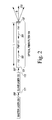
- FIG. 2 is a block diagram of one embodiment of an optical-fiber filter in accordance with the present invention.
- Figure 3 is a block diagram of one embodiment of a resonator-fiber-optic gyroscope system that includes optical-fiber filters in accordance with the present invention
- Figure 4 is a block diagram of one embodiment of an optical-fiber filter coupled to a pigtailed intensity modulator in accordance with the present invention.
- Figure 5 is a flow diagram of one embodiment of a method to generate at least one low-noise, coherent optical beam for use in a resonator-fiber-optic gyroscope system in accordance with the present invention.
- Embodiments of the resonator-fiber-optic gyroscopes described herein include a frequency stabilized reference laser to provide a reference optical beam with low phase noise for the RFOG system.
- the lasers (slaves) that are used for measuring the resonance frequency of the sensing resonator are phase locked with a servo to the reference (master) laser so that the low phase noise of the master laser within the servo bandwidth is transferred to the slave lasers.
- the master laser is frequency stabilized by using a frequency discriminator in a negative feedback loop that controls out the phase/frequency fluctuations of the master laser.
- the slave lasers have low noise within the bandwidth of the electro-optic servo.
- the embodiments of the resonator-fiber-optic gyroscopes described herein include optical-fiber filters coupled to receive output from each slave laser.
- the optical-fiber filters reduce the remaining phase noise of each laser; namely phase fluctuations at higher frequencies than the servo bandwidth.
- Outputs from the optical-fiber filters are used to probe the resonances of the fiber resonator coil (gyro sensing coil).
- the optical-fiber filters have the desired features needed for high performance rotation measurement by the RFOG. These desired features include very narrow bandwidth, small size, high power handling capability, low spurious back reflections, manufacturability, tunability, and potential for low cost.
- the optical-fiber filter described herein is a very high finesse, narrow linewidth, and low cost filter.
- FIG. 1 is a block diagram of one embodiment of an optical-fiber filter 100 in accordance with the present invention.
- the optical-fiber filter 100 includes a solid core optical fiber 110 that has a first end-face 112 and an opposing second end-face 114. The distance between the first end-face 112 and the second end-face 114 sets (determines the extent of) the fiber length L.
- the first end-face 112 is coated with a reflective coating 135.
- the second end-face 114 is coated with a reflective coating 136.
- the reflective coating 135 and reflective coating 136 include one or more layers of material deposited on the first end-face 112 and the second end-face 114, respectively.
- the reflective coating 135 and reflective coating 136 are a plurality of dielectric layers.
- a laser 201 emits an optical beam 300 (represented by an arrow).
- the optical beam 300 is incident on the reflective coating 135 and the end-face 112 and is coupled to the optical fiber 110.
- the reflective coatings 135 and 136 form a resonant cavity so the optical beam 305 coupled into the optical fiber 110 is reflected multiple times between the reflective coating 135 and reflective coating 136.
- the term "coupling” as used herein is "optically coupling" in which at least a portion of light (depending on the coupling efficiency) emitted (output) from a source (a laser or an optical fiber) is coupled into a receiving optical fiber.
- the coupling can be provided directly from the source to the receiving optical fiber (e.g., butt-coupling) or the coupling can be provided by optical elements positioned between the source and the receiving optical fiber to align and direct the optical beam output from the source.
- the coupled light propagates in the receiving optical fiber.
- the coupling efficiency is maximized when the numerical aperture of the source and fiber are matched.
- lenses (not shown) are arranged between the source and fiber to optimize the coupling.
- the optical beam 310 that is output from the opposing second end-face 114 through the reflective coating 136 has a narrow linewidth and low frequency noise fluctuations.
- the finesse of the resonator cavity formed by the reflective coating 135 and reflective coating 136 is 1000 and the length of the fiber is approximately 5 meters and the linewidth of the optical beam 310 is 20 KHz.
- the finesse of the resonator cavity formed by the reflective coating 135 and reflective coating 136 is 200 and the length of the fiber is approximately 5 meters and the linewidth of the optical beam 310 is 100 KHz.
- the reflective coating 135 and reflective coating 136 are Bragg gratings written within the fiber to produce the desired reflectivity.
- the optical-fiber filter 100 is bidirectional, so when an optical beam 300 emitted from a laser 201 is coupled into either the first end-face 112 or the second end-face 114, an optical beam output 310 from the opposing end-face has a narrow linewidth and low frequency noise fluctuations.
- the angle of the end-face cleave must be specified to promote the multiple reflections within the fiber 110 (typically, 90 degrees with respect to the core of the fiber), and the length L of the fiber, the reflectivities R 1 and R 2 of the coatings, and the mode field size and numerical aperture (NA) of the fiber must be selected to: 1) reduce the possibility of Stimulated Brillouin Scattering and other non-linear effects; 2) allow the desired power throughput; 3) achieve the desired filter linewidth; and 4) allow for the desired packaging bend diameter.
- the reflectivities R 1 and R 2 each represent the ratio of the light intensity reflected (from the surfaces) to the intensity of light incident on that surface.
- FIG. 2 is a block diagram of one embodiment of an optical-fiber filter 101 in accordance with the present invention.
- the optical-fiber filter 101 includes a solid core polarization maintaining fiber (PMF) 111 that has a first end-face 112 and an opposing second end-face 114.
- PMF solid core polarization maintaining fiber
- the reflective coatings can be directly formed on the ends of the polarization maintaining fiber 111 so the polarization maintaining fiber 111 becomes a high finesse resonator.
- the first end-face 112 is coated a first plurality of dielectric layers (thin film layers) that form a reflective coating 131.
- the second end-face is coated with a second plurality of dielectric layers (thin film layers) that form a reflective coating 132.
- the reflective coatings 131 and 132 are each a single thin film layer.
- a master laser 200 emits an optical beam 308 (represented by an arrow).
- the master laser 200 is a frequency stabilized master laser outputting a reference optical beam 308 having low phase noise.
- the optical beam 308 can have a frequency noise substantially smaller than a few Hz/ ⁇ Hz within the servo bandwidth, but may have much higher noise level at frequency region higher than servo bandwidth.
- the optical beam 308 output from the master laser 200 is used to phase lock the slave laser 120.
- the slave laser 120 emits an optical beam 307 from the output end-face 172.
- the optical beam 307 is coupled into the optical-fiber filter 101.
- the coupled optical beam 305 propagates multiple times in the resonant cavity formed in the polarization maintaining fiber 111 between the reflective coating 131 and reflective coating 132.
- the optical beam 310 that is output from the opposing second end-face 114 through the reflective coating 136 has a narrow linewidth and low frequency noise fluctuations.
- the optical beam 310 can have a frequency noise level substantially lower than a few Hz/ ⁇ Hz outside servo bandwidth.
- the coatings 131 and 132 are typically a dielectric stack designed for the desired transmission and reflection with low loss.
- the desired coatings 131 and 131 are low loss, highly reflective mirrors with a small amount of transmission, so that light incident on the input end-face 171 and the output end-face 172 is mostly reflected back into the fiber to produce a resonator.
- the small coefficient of transmission allows some light to be coupled into and out of the fiber resonator 100 or 101.
- both ends of the fibers 110 and 111 are coated.
- the reflectivity R 1 of the reflective coating 135 (131) is 0.98 and reflectivity R 2 of the reflective coating 136 (or 132) is 0.97.
- the reflectivity R 1 of the reflective coating 135 (131) is 0.98 and reflectivity R 2 of the reflective coating 136 (or 132) is 0.98. In yet another implementation of this embodiment, the reflectivity R 1 of the reflective coating 135 (131) is 0.983 and reflectivity R 2 of the reflective coating 136 (or 132) is 0.983.
- the resonator round-trip path length 2L is uniquely defined as the path length from the first fiber end-face 112, through the fiber 110 or 111 to the second coated fiber end-face 114, and back through the fiber 110 or 111 to the first fiber end-face 112. This provides for maximum stability of the optical-fiber filter 100 or 101.
- High finesse and narrow linewidth are desirable conditions to provide an optical-fiber filter (low pass filter) with a low cutoff frequency. The lower the cutoff frequency of the filter is, the lower the laser frequency noise.
- the transfer function for passing frequency noise fluctuations looks like that of a low pass electrical filter, where the filter does not reduce frequencies below its corner frequency, but rolls off, or progressively attenuates frequencies further and further beyond its corner frequency.
- the corner frequency is proportional to its linewidth.
- the optical fibers 110 ( Figure 1 ) and 111 ( Figure 2 ) have a relatively long path length and thus, provide a long optical delay time for filtering high frequency noise.
- Careful design of the optical-fiber filter 101 (100) is required to ensure the resonant optical beam does not excite non-linear effects in the fiber's core. These non-linear effects, such as the Kerr Effect, and Stimulated Brillouin Scattering (SBS), degrade the stability of the optical-fiber filter and diminish the usefulness of the output beam 310.
- SBS Stimulated Brillouin Scattering
- the power circulating in the optical-fiber filter is much more intense than the output. If the circulating power is too high within the optical-fiber filter, stimulated Brillouin scattering (SBS) is generated.
- SBS stimulated Brillouin scattering
- the fiber length L, the reflective coating 131 (135) on the first end-face 112, the reflective coating 132 (136) on the second end-face 114, a mode field size of the optical fiber 111 (110), and a numerical aperture NA of the optical fiber 111 (110) are selected to prevent generation of non-linear effects in the optical fiber 111 (110) when the optical fiber 111 (110) functions as an optical resonator.
- the exemplary fiber 111 in the optical-fiber filter 101 is a polarization maintaining (PM) fiber with a loss of 60 ppm/meter and a mode field diameter of 10.6 ⁇ .
- the power threshold at which the SBS begins (P crit Brill ) is related to the physical area of the fiber core, A, in m 2 ; the fiber loss, ⁇ , in m -1 ; and the gain coefficient of the guiding medium, G B , in m/Watt; and the length L of the fiber in meters.
- the fraction ⁇ of power in glass is 1 (i.e., for a solid core)
- the SBS gain G B is 5 x 10 -11 meters/Watt (for silica)
- a fiber mode field area is 8.8 x 10 -11 meters 2
- the power threshold for SBS, P crit Brill is 3.7 Watts.
- Table 1 shows the finesse, output power, and circulating power as a function of length L of the PM fiber 111 for a 200 KHz optical-fiber filter 101 with 200 kHz full-width-half-maximum (FWHM) peaks in the Airy function.
- Table 1 also shows the transmission (T) of the reflective coating.
- the circulating power column lists power circulating in the resonant filter in terms of unity input; the circulating power (W) column gives the circulating power in Watts, which is useful in estimating Brillouin threshold, based on an input of 60 mW.
- the circulating power does not exceed the Brillouin threshold for the lengths of fiber shown in Table 1 (e.g., less than 5 meters).
- the output and circulating powers shown in Table 1 are normalized to unity input power.
- the circulating power in watts assumes 60 mW input power.
- FIG 3 is a block diagram of one embodiment of a resonator-fiber-optic gyroscope (RFOG) system 10 that includes optical-fiber filters 101, 102, 103 in accordance with the present invention.
- the RFOG system 10 is also referred to herein as "resonator-fiber-optic gyroscope (RFOG) 10".
- the RFOG system 10 is a high performance gyroscope system. The frequency noise of each laser is reduced by the use of the optical-fiber filters 101, 102, 103.
- the RFOG 10 includes a frequency stabilized master laser 200, three slave lasers (SL) 121, 122, and 123, three respective optical-fiber filters (OFF) 101, 102, and 103, three respective intensity modulators (IM) 320-1, 320-2, and 320-3, and a fiber resonator coil 240.
- the fiber resonator coil 240 is an optical fiber ring resonator that forms a fiber ring resonant cavity in the gyroscope.
- the fiber resonator coil 240 is also referred to herein as "fiber loop 240" and "sensing resonator 240".
- the fiber loop 240 is the optical fiber through which at least two optical beams counter-propagate.
- the output of the fiber loop 240 is used to determine the rate of rotation of the RFOG 10.
- the master laser 200 and the three slave lasers (SL) 121, 122, and 123 are semiconductor laser diodes.
- the frequency stabilized master laser 200 emits a reference optical beam 308.
- the reference optical beam 308 has low phase noise (e.g., less than 1 Hz/ ⁇ Hz).
- the beam 308 is used to generate radio frequency (RF) beat signals between the master and slave lasers, which are used by phase locked loop (PLL) 250 (also referred to herein as "multi-laser frequency control 250") to lock the slave lasers 121, 122, and 123 to the master laser 200 with frequency separations determined by the resonance tracking servos 251.
- PLL phase locked loop
- multi-laser frequency control 250 also receives feedback from resonance tracking servos 251, to precisely control the frequency of the optical beams of the respective slave lasers 121, 122, and 123.
- the slave lasers 121, 122, and 123 have similar structure and function to the slave laser 120 shown in Figure 2 .
- the free spectral range (FSR) is the wavelength separation between adjacent resonance peaks of the sensing resonator 240.
- the optical-fiber filters 101, 102, and 103 are arranged so that the respective output optical beams 307-1, 307-2, and 307-3 emitted from the slave lasers 121, 122, and 123 are coupled to the respective optical-fiber filters 101, 102, and 103.
- the optical-fiber filters 101, 102, and 103 output low-noise, coherent optical beams 310-1, 310-2, and 310-3, respectively.
- the low-noise, coherent optical beams 310-1, 310-2, and 310-3 are coupled into respective intensity modulators 320-1, 320-2, and 320-3.
- the frequency noise of an optical beam is reduced, the coherence of the optical beam is increased.
- the fiber resonator coil 240 is an optical fiber that has a first coil end-face represented generally at 241 and a second coil end-face represented generally at 242.
- the low-noise, coherent optical beams 310-1 and 310-3 output from the optical-fiber filters 101 and 103 are coupled to the first coil end-face 241 of the fiber resonator coil 240 via the respective intensity modulators 320-1 and 320-3.
- the low-noise, coherent optical beam 310-2 output from the optical-fiber filter 102 is coupled to the second coil end-face 242 of the fiber resonator coil 240 via the intensity modulator 320-2.
- the optical-fiber filters 101, 102, and 103 each comprises an optical fiber 111 having a first end-face 112 and an opposing second end-face 114.
- the first end-face 112 and the second end-face 114 are coated with reflective coatings 131 and 132, respectively.
- the optical-fiber filters 101, 102, and 103 are similar in structure and function to the optical-fiber filter 100 shown in Figure 1 .
- the optical beam 307-1 emitted from the first slave laser 121 is coupled to the first end-face 112 of the first optical-fiber filter 101.
- a first low-noise, coherent optical beam 310-1 is output from the second end-face 114 of the first optical-fiber filter 101 and is coupled (via the intensity modulator 320-1 and optical elements including beam splitters 271, 272(1-2) and lens 270-1) to the first coil end-face 241 of the fiber resonator coil 240.
- Other coupling configurations of optical elements are possible as is understandable to one skilled in the art.
- the portion of the optical beam 310-1 coupled into the fiber resonator coil 240 at the first coil end-face 241 propagates through the fiber resonator coil 240 in a counter-clockwise (CCW) direction.
- CCW counter-clockwise
- the optical beam 307-2 emitted from the second slave laser 122 is coupled to the first end-face 112 of the second optical-fiber filter 102.
- a second low-noise, coherent optical beam 310-2 is output from the second end-face 114 of the second optical-fiber filter 102 and is coupled (via the intensity modulator 320-2 and optical elements including beam splitters 272(3-4) and lens 270-2) to the second coil end-face 242 of the fiber resonator coil 240.
- the portion of the optical beam 310-2 coupled into the fiber resonator coil 240 at the second coil end-face 242 propagates through the fiber resonator coil 240 in a clockwise (CW) direction.
- the optical beam 307-3 emitted from the third slave laser 131 is coupled to the first end-face 112 of the third optical-fiber filter 103.
- a third low-noise, coherent optical beam 310-3 is output from the second end-face 114 of the third optical-fiber filter 103 and is coupled (via the intensity modulator 320-3 and optical elements including the beam splitters 272(1-2) and lens 270-1) to the first coil end-face 241 of the fiber resonator coil 240.
- the portion of the optical beam 310-3 coupled into the fiber resonator coil 240 at the first coil end-face 241 propagates through the fiber resonator coil 240 in a counter-clockwise (CCW) direction.
- the lenses 270(1-2) are ball lenses.
- the light coupled into the fiber resonator coil 240 circulates multiple times within the fiber resonator coil 240 by transit through the lenses 270-1 and 270-2 and the beam splitters 272-2, 272-5, and 272-4.
- a portion (e.g., 1 to 20%) of the light propagating in the clockwise (CW) direction is reflected by beam splitter 272-5 into the detector (PD1 CW ) 261.
- a portion (e.g., 1 to 20%) of the light propagating in the counter-clockwise (CCW) direction is reflected by beam splitter 272-5 into the detector (PD2 CCW ) 262.
- Information indicative of the amount of optical power detected at the detectors 261 and 262 is sent as signals to the resonance tracking servos 251 and to the DC power servo 254.
- the resonance tracking servos 251 send signals to the multi-laser frequency control 250, which adjust the frequency of the optical beams of the slave lasers 121, 122, and 123, as needed, to resonance peaks of the sensing resonator 240.
- the DC power servo 254 sends signals to the summation circuit ( ⁇ ) 281 to adjust the power of the optical beam 310-2 output from the optical-fiber filter 102 through the intensity modulator (IM) 320-2. This adjustment is done in order to balance the power in CW and CCW direction so that optical Kerr effect induced cavity length difference is minimized.
- the exemplary RFOG 10 shown in Figure 3 also includes a relative intensity noise (RIN) detector (PD3) 262 that receives a portion (e.g., 1 to 10%) of the optical beam 310-3 from the intensity modulator 320-3 via beam splitter 258.
- RIN detector 262 measures the intensity noise of the optical beam 310-3 (before it is combined with the optical beam 310-1) that is being input to the first coil end-face 241 of the fiber resonator coil 240.
- the RIN signal from the RIN detector 262 provides signal feedback to a RIN servo electronic system 252.
- the electronic signal sent to the intensity modulator 320-3 from the RIN servo electronic system 252 adjusts the total light intensity of the input optical beam 310-3 passing through the intensity modulator 320-3, so that the undesirable fluctuations in intensity due to RIN are eliminated or substantially reduced. In this manner, the RIN servo loop is used to reduce the intensity noise or unwanted intensity or amplitude modulation of the input optical beam 310-3 passed through intensity modulator 320-3.
- the exemplary RFOG 10 shown in Figure 3 also includes a relative intensity noise (RIN) detector (PD4) 257 that receives a portion (e.g., 1 to 10%) of the optical beam 310-1 from the intensity modulator 320-1.
- RIN detector 257 measures the intensity noise of the optical beam 310-1 (before it is combined with beam 310-3) that is being input to the first coil end-face 241 of the fiber resonator coil 240.
- the RIN signal from the RIN detector 257 provides signal feedback to a RIN servo electronic system 254.
- the electronic signal sent to the intensity modulator 320-1 from the RIN servo electronic system 254 adjusts the total light intensity of the input optical beam 310-1 passing through the intensity modulator 320-1, so that the undesirable fluctuations in intensity due to RIN are eliminated or substantially reduced. In this manner, the RIN servo loop is used to reduce the intensity noise or unwanted intensity or amplitude modulation of the input optical beam 310-1 passed through intensity modulator 320-1.
- the exemplary RFOG 10 shown in Figure 3 also includes a RIN detector (PD0) 260 that receives a portion (e.g., 1 to 10%) of the optical beam 310-2 from the intensity modulator 320-2.
- the RIN signal from the RIN detector 260 provides signal feedback to a RIN servo electronic system 253.
- the electronic signal sent to the intensity modulator 320-2 from the RIN servo electronic system 253 adjusts the total light intensity of the input optical beam 310-2 passing through the intensity modulator 320-2, so that the undesirable fluctuations in intensity due to RIN are eliminated or substantially reduced. In this manner, the RIN servo loop is used to reduce the intensity noise or unwanted intensity or amplitude modulation of the input optical beam 310-2 passed through intensity modulator 320-2.
- the exemplary RFOG 10 shown in Figure 3 also includes a silicon optical bench (SiOB) 150.
- the silicon optical bench 150 includes grooves 295 and 296 etched into a surface of the silicon optical bench 150 to optically align the first fiber coil end-face 241 and the second coil end-face 242 to each other.
- the silicon optical bench 150 also includes provisions (such as, grooves, alignment features, or trenches) for positioning of optical elements (such as, lenses, beam splitters, and/or mirrors) used to align and direct optical beams 310-1, 310-3 into fiber end-face 241, and beam 310-2 into fiber end-face 242.
- the first coil end-face 241 of the fiber resonator coil 240 is positioned in a first groove 295 in the silicon optical bench 150.
- the second coil end-face 242 of the fiber resonator coil 240 is positioned in the second groove 296 in the silicon optical bench 150.
- the grooves 295 and 296 are etched to a depth such that the center of the core of the optical fiber of the fiber resonator coil 240 is precisely aligned to the optical beams 310(1-3) when the first coil end-face 241 and the second coil end-face 242 are positioned in the grooves 295 and 296.
- the grooves 295 and 296 are etched to a depth such that the core of the first coil end-face 241 and the second coil end-face 242 are aligned to each other to create the fiber ring resonant cavity.
- FIG 4 is a block diagram of one embodiment of an optical-fiber filter 101 coupled to a pigtailed intensity modulator 320-1 ( Figure 3 ) in accordance with the present invention.
- a fiber pigtail 503 with an end-face 505 is coupled to couple the input beam 310-1 to the intensity modulator 320-1.
- the end-face 505 of the fiber pigtail 503 is positioned in a groove 152 of a silicon substrate 151.
- the first ball lens 161 and the second ball lens 162 are positioned in an etched region 155 of the silicon substrate 151.
- the output end of the optical-fiber filter 101 is positioned in a groove 153 (also referred to herein as third groove 153) in the silicon optical bench 151.
- the two ball lenses 161 and 162 couple the optical beam 310-1 output from the optical-fiber filter 101 into the end-face 505 of the fiber pigtail 503 of the intensity modulator 320-1.
- the first ball lens 161 and the second ball lens 162 are positioned to collimate the low-noise, coherent optical beam propagating there between.
- the optical beam 310-1 coupled from the optical-fiber filter 101 to the first ball lens 161 exits the first ball lens 161 as a collimated optical beam 310-1'.
- the collimated optical beam 310-1' is incident on the second ball lens 162.
- the second ball lens 162 focuses the light as optical beam 310-1" on the end-face 505 of the fiber pigtail 503 of the intensity modulator 320-1.
- optical components are positioned in the collimated optical beam 310-1' to direct the light 310-1' between the first ball lens 161 and the second ball lens 162.
- there may be trenches (not shown in the silicon optical bench 151) to hold the light directing components.
- the output of the intensity modulator 320-1 may be coupled into the silicon optical bench 150 by laying an output fiber pigtail (not shown) of the intensity modulator 320-1 into groove 297 ( Figure 3 ) to couple input beam 310-1 into the resonator fiber end-face 241 via beam splitters 271, 272(1-2) and lens 270-1 located on the silicon optical bench 150 ( Figure 3 ).
- a similar arrangement is possible to couple the optical beams 310-2 and 310-3 output from the optical-fiber filters 102 and 103, respectively, to fiber pigtails of the intensity modulators 320-2 and 320-3, respectively, via silicon substrates (not shown).
- a third ball lens (not shown) and a fourth ball lens (not shown) can be configured to collimate the low-noise, coherent optical beam 310-2 propagating there between.
- the second end-face 114 of the first optical-fiber filter 101 is positioned in a third groove 297 in the silicon optical bench 150; the second end-face 114 of the second optical-fiber filter 102 is positioned in a fourth groove 298 in the silicon optical bench 150; and the second end-face 114 of the third optical-fiber filter 103 is positioned in a fifth groove 299 in the silicon optical bench 150.
- an integrated silicon optical bench is used to align optical beam outputs from the optical-fiber filters 101, 102, and 103 to the intensity modulators 320-1, 320-2, and 320-3, respectively, and to align the output of the intensity modulators 320-1, 320-2, and 320-3 to the fiber resonator coil 240.
- only one optically transparent ball lens 161 is positioned in an etched region in the silicon optical bench 150.
- the first ball lens 161 and the second ball lens 162 are positioned in two separate etched regions of the silicon optical bench 150 and/or 151.
- at least one optically transparent ball lens 161 couples the optical beams 310-1, 310-2, and/or 310-3 output from a second end-face 114 of at least one of the optical-fiber filters 101, 102 and/or 103, respectively, to at least one respective coil end-face 241, 242, or 241, respectively, of the fiber resonator coil 240.
- silicon optical benches 151 and/or 150 include grooves (e.g., grooves 297-299, 152, 152, and/or etched regions 155) to position optical elements (e.g., first ball lens 161, second ball lens 162, beam splitters 271, 272(1-5), and/or lens 270(1-2)), which align and direct at least two low-noise, coherent optical beams (e.g., 310(1-3)) output from the at least two optical-fiber filters (e.g., 101-103) to the first coil end-face 241 and the second coil end-face 242 and between the first coil end-face 241 and the second coil end-face 242. Housing the fiber resonator coil 240 on a silicon optical bench 150 provides a low cost implementation of the RFOG 10.
- optical elements e.g., first ball lens 161, second ball lens 162, beam splitters 271, 272(1-5), and/or lens 270(1-2)
- at least two optical-fiber filters e.g., 101-103
- FIG 5 is a flow diagram of one embodiment of a method 500 to generate at least one low-noise, coherent optical beam for use in a resonator-fiber-optic gyroscope system 10 in accordance with the present invention.
- the method 500 is described with reference to Figures 2 and 3 although it is to be understood that RFOGs configured with other coupling arrangements can be used.
- an optical beam 308 emitted from a master laser 200 is used to control at least one slave laser 121.
- the at least one slave laser 121 is locked to the master laser 200.
- the three slave lasers 121, 122, and 123 are locked to the master laser 200 with frequency separations determined by the resonance tracking servos 251.
- an optical beam 307 emitted from the at least one slave laser 121 is coupled to a respective at least one optical-fiber filter 101.
- the optical beam 307 output from the at least one slave laser 120 is coupled to the first end-face 112 of the respective at least one optical-fiber filter 101.
- At block 506 at least one low-noise, coherent optical beam 310 is output from the respective at least one optical-fiber filter 101.
- a low-noise, coherent optical beam 310-1 is output from the second end-face 114 of the first optical-fiber filter 101;
- a low-noise, coherent optical beam 310-2 is output from the second end-face 114 of the second optical-fiber filter 102;
- a low-noise, coherent optical beam 310-3 is output from the second end-face 114 of the third optical-fiber filter 103.
- the at least one low-noise, coherent optical beam 310-1 output from the second end-face 114 of the at least one optical-fiber filter 101 is coupled to at least one of two coil end-faces (such as, first coil end-face 241 and second coil end-face 242) of a fiber resonator coil 240 that has resonance frequencies that are sensitive to rotation rate.
- the low-noise, coherent optical beam 310-1 output from the second end-face 114 of the first optical-fiber filter 101 is coupled to the first coil end-face 241 of the fiber resonator coil 240 via the intensity modulator 320-1 and other optical elements positioned to align and direct the low-noise, coherent optical beam 310-1 output to the first coil end-face 241.
- Figure 3 shows the low-noise, coherent optical beam 310-2 output from the second end-face 114 of the second optical-fiber filter 102 is coupled to the second coil end-face 242 of the fiber resonator coil 240 via the intensity modulator 320-2 and other optical elements positioned to align and direct the low-noise, coherent optical beam 310-2 output to the second coil end-face 242.
- Figure 3 shows the low-noise, coherent optical beam 310-3 output from the second end-face 114 of the third optical-fiber filter 103 is coupled to the first coil end-face 241 of the fiber resonator coil 240 via the intensity modulator 320-3 and other optical elements positioned to align and direct the low-noise, coherent optical beam 310-3 output to the first coil end-face 241.
- the first coil end-face 241 is positioned in a first groove 295 in a silicon optical bench 150 and a second coil end-face 242 is positioned in a second groove 296 in the silicon optical bench 150.
- the first low-noise, coherent optical beam 310-1 is coupled to the first coil end-face 241 positioned in a first groove 295 in the silicon optical bench 150 via at least one ball lens 161 positioned in a first etched region 155 of the silicon optical bench 150;
- the second low-noise, coherent optical beam 310-2 is coupled to the second coil end-face 242 positioned in the second groove 296 in the silicon optical bench 150 via at least one ball lens 161 positioned in a second etched region 155 of the silicon optical bench 155;
- the third low-noise, coherent optical beam 310-3 is coupled to the first coil end-face 241 positioned in the first groove 295 in the silicon optical bench 150 via at least one ball lens 161 positioned in a third etched region 299 of the silicon optical bench 155.
- the intensity modulation function is done directly on the optical-fiber filter 101, 102 and 103.
- the second end-face 114 of the first optical-fiber filter 101 is positioned in a third groove 297 in the silicon optical bench 150
- the second end-face 114 of the second optical-fiber filter 102 is positioned in a fourth groove 298 in the silicon optical bench 150
- the second end-face 114 of the third optical-fiber filter 103 is positioned in a fifth groove 299 in the silicon optical bench 150.
- there is no third optical-fiber filter 103 is positioned in a fifth groove 299.
- an inexpensive RFOG system uses low cost laser diodes and improves optical filtering (by use of the optical-fiber filters) to reduce the phase noise of the laser diodes, so the low cost RFOG system has an improved performance.
- the optical-fiber filter 100 or 101 is used in a system that includes a single laser and a frequency shifter.
Landscapes
- Physics & Mathematics (AREA)
- Engineering & Computer Science (AREA)
- Optics & Photonics (AREA)
- Electromagnetism (AREA)
- Power Engineering (AREA)
- General Physics & Mathematics (AREA)
- Radar, Positioning & Navigation (AREA)
- Remote Sensing (AREA)
- Gyroscopes (AREA)
- Light Guides In General And Applications Therefor (AREA)
- Optical Couplings Of Light Guides (AREA)
- Optical Fibers, Optical Fiber Cores, And Optical Fiber Bundles (AREA)
Abstract
Description
- This invention was made with Government support under N00014-08-C-0665 awarded by Office of Naval Research. The Government has certain rights in the invention.
- A resonator-fiber-optic gyroscope (RFOG) is a rotation rate measurement apparatus that uses a fiber ring resonant cavity to enhance the signal to noise ratio in the measurement of rotation-induced Sagnac effect within the resonant cavity. The basic principle of RFOG operation is that the effective resonator path length in a clockwise (CW) and counter-clockwise (CCW) direction is different when the rotation of the fiber ring resonant cavity has a nonzero component in a resonator axis. By measuring the CW and CCW resonance frequency difference, which is proportional to Sagnac phase shift due to rotation, the RFOG can accurately measure the rotation rate.
- Lasers provide coherent light to the fiber resonator to identify its resonance frequencies. Semiconductor lasers are a low cost option for source lasers. However, semiconductor lasers typically have significant phase noise that can lead to degradation of the RFOG performance.
- The present application relates to an optical-fiber filter. The optical-fiber filter includes an optical fiber having a first end-face and an opposing second end-face. The first end-face and the second end-face set a fiber length. The first end-face and the second end-face are coated with reflective coatings. When an optical beam emitted from a laser is coupled into one of the first end-face or the second end-face, an optical beam output from the opposing end-face has a narrow linewidth and low frequency noise fluctuations.
- The details of various embodiments of the claimed invention are set forth in the accompanying drawings and the description below. Other features and advantages will become apparent from the description, the drawings, and the claims.
-
Figure 1 is a block diagram of one embodiment of an optical-fiber filter in accordance with the present invention; -
Figure 2 is a block diagram of one embodiment of an optical-fiber filter in accordance with the present invention; -
Figure 3 is a block diagram of one embodiment of a resonator-fiber-optic gyroscope system that includes optical-fiber filters in accordance with the present invention; -
Figure 4 is a block diagram of one embodiment of an optical-fiber filter coupled to a pigtailed intensity modulator in accordance with the present invention; and -
Figure 5 is a flow diagram of one embodiment of a method to generate at least one low-noise, coherent optical beam for use in a resonator-fiber-optic gyroscope system in accordance with the present invention. - Like reference numbers and designations in the various drawings indicate like elements.
- In order for laser diodes to be used in a resonator-fiber-optic gyroscope (RFOG) without degrading performance, the phase noise of lasers must be reduced. Embodiments of the resonator-fiber-optic gyroscopes described herein include a frequency stabilized reference laser to provide a reference optical beam with low phase noise for the RFOG system. The lasers (slaves) that are used for measuring the resonance frequency of the sensing resonator are phase locked with a servo to the reference (master) laser so that the low phase noise of the master laser within the servo bandwidth is transferred to the slave lasers. The master laser is frequency stabilized by using a frequency discriminator in a negative feedback loop that controls out the phase/frequency fluctuations of the master laser. Thus, the slave lasers have low noise within the bandwidth of the electro-optic servo.
- The embodiments of the resonator-fiber-optic gyroscopes described herein include optical-fiber filters coupled to receive output from each slave laser. The optical-fiber filters reduce the remaining phase noise of each laser; namely phase fluctuations at higher frequencies than the servo bandwidth. Outputs from the optical-fiber filters are used to probe the resonances of the fiber resonator coil (gyro sensing coil). The optical-fiber filters have the desired features needed for high performance rotation measurement by the RFOG. These desired features include very narrow bandwidth, small size, high power handling capability, low spurious back reflections, manufacturability, tunability, and potential for low cost. The optical-fiber filter described herein is a very high finesse, narrow linewidth, and low cost filter.
-
Figure 1 is a block diagram of one embodiment of an optical-fiber filter 100 in accordance with the present invention. The optical-fiber filter 100 includes a solid coreoptical fiber 110 that has a first end-face 112 and an opposing second end-face 114. The distance between the first end-face 112 and the second end-face 114 sets (determines the extent of) the fiber length L. The first end-face 112 is coated with areflective coating 135. The second end-face 114 is coated with areflective coating 136. In one implementation of this embodiment, thereflective coating 135 andreflective coating 136 include one or more layers of material deposited on the first end-face 112 and the second end-face 114, respectively. In another implementation of this embodiment, thereflective coating 135 andreflective coating 136 are a plurality of dielectric layers. - As shown in
Figure 1 , alaser 201 emits an optical beam 300 (represented by an arrow). Theoptical beam 300 is incident on thereflective coating 135 and the end-face 112 and is coupled to theoptical fiber 110. Thereflective coatings optical beam 305 coupled into theoptical fiber 110 is reflected multiple times between thereflective coating 135 andreflective coating 136. The term "coupling" as used herein is "optically coupling" in which at least a portion of light (depending on the coupling efficiency) emitted (output) from a source (a laser or an optical fiber) is coupled into a receiving optical fiber. The coupling can be provided directly from the source to the receiving optical fiber (e.g., butt-coupling) or the coupling can be provided by optical elements positioned between the source and the receiving optical fiber to align and direct the optical beam output from the source. The coupled light propagates in the receiving optical fiber. The coupling efficiency is maximized when the numerical aperture of the source and fiber are matched. In one implementation of this embodiment, lenses (not shown) are arranged between the source and fiber to optimize the coupling. - The
optical beam 310 that is output from the opposing second end-face 114 through thereflective coating 136 has a narrow linewidth and low frequency noise fluctuations. In one implementation of this embodiment, the finesse of the resonator cavity formed by thereflective coating 135 andreflective coating 136 is 1000 and the length of the fiber is approximately 5 meters and the linewidth of theoptical beam 310 is 20 KHz. In another implementation of this embodiment, the finesse of the resonator cavity formed by thereflective coating 135 andreflective coating 136 is 200 and the length of the fiber is approximately 5 meters and the linewidth of theoptical beam 310 is 100 KHz. In one implementation of this embodiment, thereflective coating 135 andreflective coating 136 are Bragg gratings written within the fiber to produce the desired reflectivity. - The optical-
fiber filter 100 is bidirectional, so when anoptical beam 300 emitted from alaser 201 is coupled into either the first end-face 112 or the second end-face 114, anoptical beam output 310 from the opposing end-face has a narrow linewidth and low frequency noise fluctuations. - In the optical-
fiber filter 100, the angle of the end-face cleave must be specified to promote the multiple reflections within the fiber 110 (typically, 90 degrees with respect to the core of the fiber), and the length L of the fiber, the reflectivities R1 and R2 of the coatings, and the mode field size and numerical aperture (NA) of the fiber must be selected to: 1) reduce the possibility of Stimulated Brillouin Scattering and other non-linear effects; 2) allow the desired power throughput; 3) achieve the desired filter linewidth; and 4) allow for the desired packaging bend diameter. The divergence angle θ of theoptical beam 310 and the index of refraction n of theoptical fiber 110 are used to calculate the numerical aperture NA, which is NA = n sin θ, where n is the refractive index of the medium outside the optical filter. The reflectivities R1 and R2 each represent the ratio of the light intensity reflected (from the surfaces) to the intensity of light incident on that surface. -
Figure 2 is a block diagram of one embodiment of an optical-fiber filter 101 in accordance with the present invention. The optical-fiber filter 101 includes a solid core polarization maintaining fiber (PMF) 111 that has a first end-face 112 and an opposing second end-face 114. Advantageously, the reflective coatings can be directly formed on the ends of thepolarization maintaining fiber 111 so thepolarization maintaining fiber 111 becomes a high finesse resonator. The first end-face 112 is coated a first plurality of dielectric layers (thin film layers) that form areflective coating 131. The second end-face is coated with a second plurality of dielectric layers (thin film layers) that form areflective coating 132. In one implementation of this embodiment, thereflective coatings - As shown in
Figure 2 , amaster laser 200 emits an optical beam 308 (represented by an arrow). In one implementation of this embodiment, themaster laser 200 is a frequency stabilized master laser outputting a referenceoptical beam 308 having low phase noise. For example, theoptical beam 308 can have a frequency noise substantially smaller than a few Hz/√Hz within the servo bandwidth, but may have much higher noise level at frequency region higher than servo bandwidth. Theoptical beam 308 output from themaster laser 200 is used to phase lock theslave laser 120. Theslave laser 120 emits anoptical beam 307 from the output end-face 172. Theoptical beam 307 is coupled into the optical-fiber filter 101. The coupledoptical beam 305 propagates multiple times in the resonant cavity formed in thepolarization maintaining fiber 111 between thereflective coating 131 andreflective coating 132. Theoptical beam 310 that is output from the opposing second end-face 114 through thereflective coating 136 has a narrow linewidth and low frequency noise fluctuations. For example, theoptical beam 310 can have a frequency noise level substantially lower than a few Hz/√Hz outside servo bandwidth. - The
coatings coatings face 171 and the output end-face 172 is mostly reflected back into the fiber to produce a resonator. The small coefficient of transmission allows some light to be coupled into and out of thefiber resonator Figures 1 and2 , both ends of thefibers - The resonator round-trip path length 2L is uniquely defined as the path length from the first fiber end-
face 112, through thefiber face 114, and back through thefiber face 112. This provides for maximum stability of the optical-fiber filter - The optical fibers 110 (
Figure 1 ) and 111 (Figure 2 ) have a relatively long path length and thus, provide a long optical delay time for filtering high frequency noise. Careful design of the optical-fiber filter 101 (100) is required to ensure the resonant optical beam does not excite non-linear effects in the fiber's core. These non-linear effects, such as the Kerr Effect, and Stimulated Brillouin Scattering (SBS), degrade the stability of the optical-fiber filter and diminish the usefulness of theoutput beam 310. In an optical resonator, the power circulating in the optical-fiber filter is much more intense than the output. If the circulating power is too high within the optical-fiber filter, stimulated Brillouin scattering (SBS) is generated. Stimulated Brillouin scattering causes large intensity fluctuations which corrupt the output of the optical-fiber filter. The fiber length L, the reflective coating 131 (135) on the first end-face 112, the reflective coating 132 (136) on the second end-face 114, a mode field size of the optical fiber 111 (110), and a numerical aperture NA of the optical fiber 111 (110) are selected to prevent generation of non-linear effects in the optical fiber 111 (110) when the optical fiber 111 (110) functions as an optical resonator. - The limits of an exemplary optical-
fiber filter 101 designed to prevent generation of non-linear effects are now described. Theexemplary fiber 111 in the optical-fiber filter 101 is a polarization maintaining (PM) fiber with a loss of 60 ppm/meter and a mode field diameter of 10.6µ. The power threshold at which the SBS begins (Pcrit Brill) is related to the physical area of the fiber core, A, in m2; the fiber loss, α, in m-1; and the gain coefficient of the guiding medium, GB, in m/Watt; and the length L of the fiber in meters. Specifically, Pcrit Brill is calculated based on the following equation, where "*" is representative of the multiplicative sign: Pcrit Brill =21 * [(a*Aeff)/(ρ*gB*(1-e-(αL))]. For a nominal 10 meterpolarization maintaining fiber 111 in which the loss α is 0.25 dB/km (∼60 ppm/m), the fraction ρ of power in glass is 1 (i.e., for a solid core), the SBS gain GB is 5 x 10-11 meters/Watt (for silica), and a fiber mode field area is 8.8 x 10⁻¹¹ meters2, the power threshold for SBS, Pcrit Brill, is 3.7 Watts. - Table 1 shows the finesse, output power, and circulating power as a function of length L of the
PM fiber 111 for a 200 KHz optical-fiber filter 101 with 200 kHz full-width-half-maximum (FWHM) peaks in the Airy function. Table 1 also shows the transmission (T) of the reflective coating. The circulating power column lists power circulating in the resonant filter in terms of unity input; the circulating power (W) column gives the circulating power in Watts, which is useful in estimating Brillouin threshold, based on an input of 60 mW. - When a 60 mW laser beam is coupled into the exemplary optical-
fiber filter 101 described above, the circulating power does not exceed the Brillouin threshold for the lengths of fiber shown in Table 1 (e.g., less than 5 meters). The output and circulating powers shown in Table 1 are normalized to unity input power. The circulating power in watts assumes 60 mW input power.TABLE 1 Length (meters) Finesse Output Power Circulating Power Circulating Power (W) T 3.0 172 0.875 54.90 3.29 0.0170 3.5 147 0.890 47.09 2.82 0.0200 4.0 129 0.901 41.17 2.47 0.0231 4.5 115 0.910 36.59 2.20 0.0261 5.0 103 0.917 32.93 1.98 0.0291 -
Figure 3 is a block diagram of one embodiment of a resonator-fiber-optic gyroscope (RFOG)system 10 that includes optical-fiber filters RFOG system 10 is also referred to herein as "resonator-fiber-optic gyroscope (RFOG) 10". TheRFOG system 10 is a high performance gyroscope system. The frequency noise of each laser is reduced by the use of the optical-fiber filters RFOG 10 includes a frequency stabilizedmaster laser 200, three slave lasers (SL) 121, 122, and 123, three respective optical-fiber filters (OFF) 101, 102, and 103, three respective intensity modulators (IM) 320-1, 320-2, and 320-3, and afiber resonator coil 240. Thefiber resonator coil 240 is an optical fiber ring resonator that forms a fiber ring resonant cavity in the gyroscope. Thefiber resonator coil 240 is also referred to herein as "fiber loop 240" and "sensingresonator 240". Thefiber loop 240 is the optical fiber through which at least two optical beams counter-propagate. The output of thefiber loop 240 is used to determine the rate of rotation of theRFOG 10. In one implementation of this embodiment, there are only two optical-fiber filters respective slave lasers master laser 200 and the three slave lasers (SL) 121, 122, and 123 are semiconductor laser diodes. - The frequency stabilized
master laser 200 emits a referenceoptical beam 308. The referenceoptical beam 308 has low phase noise (e.g., less than 1 Hz/√Hz). Thebeam 308 is used to generate radio frequency (RF) beat signals between the master and slave lasers, which are used by phase locked loop (PLL) 250 (also referred to herein as "multi-laser frequency control 250") to lock theslave lasers master laser 200 with frequency separations determined by theresonance tracking servos 251. These beat signals are used bymulti-laser frequency control 250, which receives feedback fromresonance tracking servos 251, to precisely control the frequency of the optical beams of therespective slave lasers - The
slave lasers slave laser 120 shown inFigure 2 . As shown inFigure 3 , theslave laser 121 is locked to the reference optical beam 308-1 such thatslave laser 121 emits light at a first frequency f1 = f + Δf - FSR, where f is the central frequency ofmaster laser 200, Δf is a frequency offset from the central frequency f, and the FSR is the free spectral range of thesensing resonator 240. The free spectral range (FSR) is the wavelength separation between adjacent resonance peaks of thesensing resonator 240. Theslave laser 122 is locked to the reference optical beam 308-2 such thatslave laser 123 emits light at a second frequency f2 = f + Δf. Theslave laser 123 is locked to the reference optical beam 308-3 such thatslave laser 123 emits light at a third frequency f3 = f + Δf + FSR. - The optical-
fiber filters slave lasers fiber filters fiber filters - The
fiber resonator coil 240 is an optical fiber that has a first coil end-face represented generally at 241 and a second coil end-face represented generally at 242. The low-noise, coherent optical beams 310-1 and 310-3 output from the optical-fiber filters face 241 of thefiber resonator coil 240 via the respective intensity modulators 320-1 and 320-3. The low-noise, coherent optical beam 310-2 output from the optical-fiber filter 102 is coupled to the second coil end-face 242 of thefiber resonator coil 240 via the intensity modulator 320-2. - The optical-
fiber filters optical fiber 111 having a first end-face 112 and an opposing second end-face 114. The first end-face 112 and the second end-face 114 are coated withreflective coatings fiber filters fiber filter 100 shown inFigure 1 . - The optical beam 307-1 emitted from the
first slave laser 121 is coupled to the first end-face 112 of the first optical-fiber filter 101. A first low-noise, coherent optical beam 310-1 is output from the second end-face 114 of the first optical-fiber filter 101 and is coupled (via the intensity modulator 320-1 and optical elements includingbeam splitters 271, 272(1-2) and lens 270-1) to the first coil end-face 241 of thefiber resonator coil 240. Other coupling configurations of optical elements are possible as is understandable to one skilled in the art. The portion of the optical beam 310-1 coupled into thefiber resonator coil 240 at the first coil end-face 241 propagates through thefiber resonator coil 240 in a counter-clockwise (CCW) direction. - The optical beam 307-2 emitted from the
second slave laser 122 is coupled to the first end-face 112 of the second optical-fiber filter 102. A second low-noise, coherent optical beam 310-2 is output from the second end-face 114 of the second optical-fiber filter 102 and is coupled (via the intensity modulator 320-2 and optical elements including beam splitters 272(3-4) and lens 270-2) to the second coil end-face 242 of thefiber resonator coil 240. The portion of the optical beam 310-2 coupled into thefiber resonator coil 240 at the second coil end-face 242 propagates through thefiber resonator coil 240 in a clockwise (CW) direction. - The optical beam 307-3 emitted from the
third slave laser 131 is coupled to the first end-face 112 of the third optical-fiber filter 103. A third low-noise, coherent optical beam 310-3 is output from the second end-face 114 of the third optical-fiber filter 103 and is coupled (via the intensity modulator 320-3 and optical elements including the beam splitters 272(1-2) and lens 270-1) to the first coil end-face 241 of thefiber resonator coil 240. The portion of the optical beam 310-3 coupled into thefiber resonator coil 240 at the first coil end-face 241 propagates through thefiber resonator coil 240 in a counter-clockwise (CCW) direction. In one implementation of this embodiment, the lenses 270(1-2) are ball lenses. - The light coupled into the
fiber resonator coil 240 circulates multiple times within thefiber resonator coil 240 by transit through the lenses 270-1 and 270-2 and the beam splitters 272-2, 272-5, and 272-4. A portion (e.g., 1 to 20%) of the light propagating in the clockwise (CW) direction is reflected by beam splitter 272-5 into the detector (PD1CW) 261. A portion (e.g., 1 to 20%) of the light propagating in the counter-clockwise (CCW) direction is reflected by beam splitter 272-5 into the detector (PD2CCW) 262. Information indicative of the amount of optical power detected at thedetectors resonance tracking servos 251 and to theDC power servo 254. Theresonance tracking servos 251 send signals to themulti-laser frequency control 250, which adjust the frequency of the optical beams of theslave lasers sensing resonator 240. TheDC power servo 254 sends signals to the summation circuit (Σ) 281 to adjust the power of the optical beam 310-2 output from the optical-fiber filter 102 through the intensity modulator (IM) 320-2. This adjustment is done in order to balance the power in CW and CCW direction so that optical Kerr effect induced cavity length difference is minimized. - The
exemplary RFOG 10 shown inFigure 3 also includes a relative intensity noise (RIN) detector (PD3) 262 that receives a portion (e.g., 1 to 10%) of the optical beam 310-3 from the intensity modulator 320-3 viabeam splitter 258.RIN detector 262 measures the intensity noise of the optical beam 310-3 (before it is combined with the optical beam 310-1) that is being input to the first coil end-face 241 of thefiber resonator coil 240. The RIN signal from theRIN detector 262 provides signal feedback to a RIN servoelectronic system 252. The electronic signal sent to the intensity modulator 320-3 from the RIN servoelectronic system 252 adjusts the total light intensity of the input optical beam 310-3 passing through the intensity modulator 320-3, so that the undesirable fluctuations in intensity due to RIN are eliminated or substantially reduced. In this manner, the RIN servo loop is used to reduce the intensity noise or unwanted intensity or amplitude modulation of the input optical beam 310-3 passed through intensity modulator 320-3. - The
exemplary RFOG 10 shown inFigure 3 also includes a relative intensity noise (RIN) detector (PD4) 257 that receives a portion (e.g., 1 to 10%) of the optical beam 310-1 from the intensity modulator 320-1.RIN detector 257 measures the intensity noise of the optical beam 310-1 (before it is combined with beam 310-3) that is being input to the first coil end-face 241 of thefiber resonator coil 240. The RIN signal from theRIN detector 257 provides signal feedback to a RIN servoelectronic system 254. The electronic signal sent to the intensity modulator 320-1 from the RIN servoelectronic system 254 adjusts the total light intensity of the input optical beam 310-1 passing through the intensity modulator 320-1, so that the undesirable fluctuations in intensity due to RIN are eliminated or substantially reduced. In this manner, the RIN servo loop is used to reduce the intensity noise or unwanted intensity or amplitude modulation of the input optical beam 310-1 passed through intensity modulator 320-1. - The
exemplary RFOG 10 shown inFigure 3 also includes a RIN detector (PD0) 260 that receives a portion (e.g., 1 to 10%) of the optical beam 310-2 from the intensity modulator 320-2. The RIN signal from theRIN detector 260 provides signal feedback to a RIN servoelectronic system 253. The electronic signal sent to the intensity modulator 320-2 from the RIN servoelectronic system 253 adjusts the total light intensity of the input optical beam 310-2 passing through the intensity modulator 320-2, so that the undesirable fluctuations in intensity due to RIN are eliminated or substantially reduced. In this manner, the RIN servo loop is used to reduce the intensity noise or unwanted intensity or amplitude modulation of the input optical beam 310-2 passed through intensity modulator 320-2. - The
exemplary RFOG 10 shown inFigure 3 also includes a silicon optical bench (SiOB) 150. The siliconoptical bench 150 includesgrooves optical bench 150 to optically align the first fiber coil end-face 241 and the second coil end-face 242 to each other. The siliconoptical bench 150 also includes provisions (such as, grooves, alignment features, or trenches) for positioning of optical elements (such as, lenses, beam splitters, and/or mirrors) used to align and direct optical beams 310-1, 310-3 into fiber end-face 241, and beam 310-2 into fiber end-face 242. The first coil end-face 241 of thefiber resonator coil 240 is positioned in afirst groove 295 in the siliconoptical bench 150. The second coil end-face 242 of thefiber resonator coil 240 is positioned in thesecond groove 296 in the siliconoptical bench 150. Thegrooves fiber resonator coil 240 is precisely aligned to the optical beams 310(1-3) when the first coil end-face 241 and the second coil end-face 242 are positioned in thegrooves grooves face 241 and the second coil end-face 242 are aligned to each other to create the fiber ring resonant cavity. -
Figure 4 is a block diagram of one embodiment of an optical-fiber filter 101 coupled to a pigtailed intensity modulator 320-1 (Figure 3 ) in accordance with the present invention. In this embodiment, afiber pigtail 503 with an end-face 505 is coupled to couple the input beam 310-1 to the intensity modulator 320-1. The end-face 505 of thefiber pigtail 503 is positioned in agroove 152 of asilicon substrate 151. Thefirst ball lens 161 and thesecond ball lens 162 are positioned in an etchedregion 155 of thesilicon substrate 151. The output end of the optical-fiber filter 101 is positioned in a groove 153 (also referred to herein as third groove 153) in the siliconoptical bench 151. The twoball lenses fiber filter 101 into the end-face 505 of thefiber pigtail 503 of the intensity modulator 320-1. - As shown in
Figure 4 , thefirst ball lens 161 and thesecond ball lens 162 are positioned to collimate the low-noise, coherent optical beam propagating there between. In this exemplary alignment, the optical beam 310-1 coupled from the optical-fiber filter 101 to thefirst ball lens 161 exits thefirst ball lens 161 as a collimated optical beam 310-1'. The collimated optical beam 310-1' is incident on thesecond ball lens 162. Thesecond ball lens 162 focuses the light as optical beam 310-1" on the end-face 505 of thefiber pigtail 503 of the intensity modulator 320-1. In one implementation of this embodiment, optical components (such as beam splitters 272(1-2) are positioned in the collimated optical beam 310-1' to direct the light 310-1' between thefirst ball lens 161 and thesecond ball lens 162. In such an embodiment, there may be trenches (not shown in the silicon optical bench 151) to hold the light directing components. In like manner, the output of the intensity modulator 320-1 may be coupled into the siliconoptical bench 150 by laying an output fiber pigtail (not shown) of the intensity modulator 320-1 into groove 297 (Figure 3 ) to couple input beam 310-1 into the resonator fiber end-face 241 viabeam splitters 271, 272(1-2) and lens 270-1 located on the silicon optical bench 150 (Figure 3 ). - A similar arrangement is possible to couple the optical beams 310-2 and 310-3 output from the optical-
fiber filters - In another implementation of this embodiment, the second end-
face 114 of the first optical-fiber filter 101 is positioned in athird groove 297 in the siliconoptical bench 150; the second end-face 114 of the second optical-fiber filter 102 is positioned in afourth groove 298 in the siliconoptical bench 150; and the second end-face 114 of the third optical-fiber filter 103 is positioned in afifth groove 299 in the siliconoptical bench 150. In one implementation of this embodiment, an integrated silicon optical bench is used to align optical beam outputs from the optical-fiber filters fiber resonator coil 240. - In yet another implementation of this embodiment, only one optically
transparent ball lens 161 is positioned in an etched region in the siliconoptical bench 150. In another implementation of this embodiment, thefirst ball lens 161 and thesecond ball lens 162 are positioned in two separate etched regions of the siliconoptical bench 150 and/or 151. In this manner, at least one opticallytransparent ball lens 161 couples the optical beams 310-1, 310-2, and/or 310-3 output from a second end-face 114 of at least one of the optical-fiber filters face fiber resonator coil 240. - Thus, silicon
optical benches 151 and/or 150 include grooves (e.g., grooves 297-299, 152, 152, and/or etched regions 155) to position optical elements (e.g.,first ball lens 161,second ball lens 162,beam splitters 271, 272(1-5), and/or lens 270(1-2)), which align and direct at least two low-noise, coherent optical beams (e.g., 310(1-3)) output from the at least two optical-fiber filters (e.g., 101-103) to the first coil end-face 241 and the second coil end-face 242 and between the first coil end-face 241 and the second coil end-face 242. Housing thefiber resonator coil 240 on a siliconoptical bench 150 provides a low cost implementation of theRFOG 10. -
Figure 5 is a flow diagram of one embodiment of amethod 500 to generate at least one low-noise, coherent optical beam for use in a resonator-fiber-optic gyroscope system 10 in accordance with the present invention. Themethod 500 is described with reference toFigures 2 and3 although it is to be understood that RFOGs configured with other coupling arrangements can be used. - At
block 502, anoptical beam 308 emitted from amaster laser 200 is used to control at least oneslave laser 121. The at least oneslave laser 121 is locked to themaster laser 200. The threeslave lasers master laser 200 with frequency separations determined by theresonance tracking servos 251. As shown inFigure 3 , thefirst slave laser 121 is locked to a first frequency f1 = f + Δf - FSR; thesecond slave laser 122 is locked to a second frequency f2 = f + Δf; and thethird slave laser 122 is locked to a third frequency f3 = f + Δf + FSR. - At
block 504, anoptical beam 307 emitted from the at least oneslave laser 121 is coupled to a respective at least one optical-fiber filter 101. Specifically, theoptical beam 307 output from the at least oneslave laser 120 is coupled to the first end-face 112 of the respective at least one optical-fiber filter 101. - As shown in
Figure 3 , the output 307-1 from the first slave laser 121 (at a first frequency f1 = f + Δf - FSR) is coupled to the first end-face 112 of the first optical-fiber filter 101; the output 307-2 from the second slave laser 122 (at a second frequency f2 = f + Δf) is coupled to the first end-face 112 of the second optical-fiber filter 102; and the output 307-3 from the third slave laser 123 (at a third frequency f3 = f + Δf + FSR) is coupled to the first end-face 112 of the third optical-fiber filter 103. - At
block 506, at least one low-noise, coherentoptical beam 310 is output from the respective at least one optical-fiber filter 101. As shown inFigure 3 , a low-noise, coherent optical beam 310-1 is output from the second end-face 114 of the first optical-fiber filter 101; a low-noise, coherent optical beam 310-2 is output from the second end-face 114 of the second optical-fiber filter 102; and a low-noise, coherent optical beam 310-3 is output from the second end-face 114 of the third optical-fiber filter 103. - At
block 508, the at least one low-noise, coherent optical beam 310-1 output from the second end-face 114 of the at least one optical-fiber filter 101 is coupled to at least one of two coil end-faces (such as, first coil end-face 241 and second coil end-face 242) of afiber resonator coil 240 that has resonance frequencies that are sensitive to rotation rate. - As shown in
Figure 3 , the low-noise, coherent optical beam 310-1 output from the second end-face 114 of the first optical-fiber filter 101 is coupled to the first coil end-face 241 of thefiber resonator coil 240 via the intensity modulator 320-1 and other optical elements positioned to align and direct the low-noise, coherent optical beam 310-1 output to the first coil end-face 241. - Likewise,
Figure 3 shows the low-noise, coherent optical beam 310-2 output from the second end-face 114 of the second optical-fiber filter 102 is coupled to the second coil end-face 242 of thefiber resonator coil 240 via the intensity modulator 320-2 and other optical elements positioned to align and direct the low-noise, coherent optical beam 310-2 output to the second coil end-face 242. - Likewise,
Figure 3 shows the low-noise, coherent optical beam 310-3 output from the second end-face 114 of the third optical-fiber filter 103 is coupled to the first coil end-face 241 of thefiber resonator coil 240 via the intensity modulator 320-3 and other optical elements positioned to align and direct the low-noise, coherent optical beam 310-3 output to the first coil end-face 241. In one implementation of this embodiment, there is nothird slave laser 123 and there is no optical-fiber filter 103 in theRFOG system 10. - In one implementation of this embodiment, the first coil end-
face 241 is positioned in afirst groove 295 in a siliconoptical bench 150 and a second coil end-face 242 is positioned in asecond groove 296 in the siliconoptical bench 150. - In another implementation of this embodiment, the first low-noise, coherent optical beam 310-1 is coupled to the first coil end-
face 241 positioned in afirst groove 295 in the siliconoptical bench 150 via at least oneball lens 161 positioned in a firstetched region 155 of the siliconoptical bench 150; the second low-noise, coherent optical beam 310-2 is coupled to the second coil end-face 242 positioned in thesecond groove 296 in the siliconoptical bench 150 via at least oneball lens 161 positioned in a secondetched region 155 of the siliconoptical bench 155; and the third low-noise, coherent optical beam 310-3 is coupled to the first coil end-face 241 positioned in thefirst groove 295 in the siliconoptical bench 150 via at least oneball lens 161 positioned in a thirdetched region 299 of the siliconoptical bench 155. In some embodiments of this latter configuration, there is no third low-noise, coherent optical beam 310-3 and noball lens 161 positioned in a thirdetched region 299. - In yet another implementation of this embodiment, the intensity modulation function is done directly on the optical-
fiber filter face 114 of the first optical-fiber filter 101 is positioned in athird groove 297 in the siliconoptical bench 150, the second end-face 114 of the second optical-fiber filter 102 is positioned in afourth groove 298 in the siliconoptical bench 150, and the second end-face 114 of the third optical-fiber filter 103 is positioned in afifth groove 299 in the siliconoptical bench 150. In some embodiments of this latter configuration, there is no third optical-fiber filter 103 is positioned in afifth groove 299. - In this manner, an inexpensive RFOG system uses low cost laser diodes and improves optical filtering (by use of the optical-fiber filters) to reduce the phase noise of the laser diodes, so the low cost RFOG system has an improved performance. In one implementation of this embodiment, the optical-
fiber filter - A number of embodiments of the invention defined by the following claims have been described. Nevertheless, it will be understood that various modifications to the described embodiments may be made without departing from the spirit and scope of the claimed invention. Accordingly, other embodiments are within the scope of the following claims.
Claims (10)
- A resonator-fiber-optic gyroscope (10) comprising:a frequency stabilized master laser (200) emitting a reference optical beam (308) having low phase noise;at least two slave lasers (121) arranged so that the reference optical beam controls the respective at least two slave lasers;at least two optical-fiber filters (101) arranged so that optical beams (307-1) emitted from the at least two slave lasers are coupled to the respective optical-fiber filters, wherein low-noise, coherent optical beams (310-1) are output from the respective optical-fiber filters; anda fiber resonator coil (240) having a first coil end-face (241) and a second coil end-face (242),wherein an optical beam (310-1) output from one of the at least two optical-fiber filters is coupled to the first coil end-face of the fiber resonator coil, andwherein an optical beam (310-2) output from another one of the at least two optical-fiber filters (310-2) is coupled to the second coil end-face of the fiber resonator coil.
- The resonator-fiber-optic gyroscope (10) of claim 1, wherein the at least two optical-fiber filters each comprise an optical fiber (110) having a first end-face (112) and an opposing second end-face (114), the first end-face and the second end-face setting a fiber length (L), the first end-face and the second end-face being coated with reflective coatings (135), wherein the fiber length, the reflective coating (135) on the first end-face (112), the reflective coating (136) on the second end-face (114), a mode field size of the optical fiber, and a numerical aperture of the optical fiber are selected to prevent generation of non-linear effects in the optical fibers of the at least two optical-fiber filters.
- The resonator-fiber-optic gyroscope (10) of claim 1, wherein the optical beam (307-1) output from a first slave laser (121) is coupled to a first end-face (112) of a first optical-fiber filter (101), wherein a first low-noise, coherent optical beam (310-1) output from a second end-face (114) of the first optical-fiber filter is coupled to the first coil end-face (241) of the fiber resonator coil (240), and
wherein the optical beam output (307-2) from a second slave laser (122) is coupled to a first end-face (112) of a second optical-fiber filter (102), wherein a second low-noise, coherent optical beam (310-2) output from a second end-face (114) of the second optical-fiber filter is coupled to the second coil end-face (242) of the fiber resonator coil. - The resonator-fiber-optic gyroscope (10) of claim 3, wherein the optical beam (307-3) output from a third slave laser (123) is coupled to a first end-face (112) of a third optical-fiber filter (103), wherein a third low-noise, coherent optical beam (310-3) output from a second end-face (114) of the third optical-fiber filter is coupled to the first coil end-face (241) of the fiber resonator coil (240).
- The resonator-fiber-optic gyroscope (10) of claim 1, further comprising:a silicon optical bench (150) including grooves (295) to optically align the first coil end-face (241) and the second coil end-face (242) to respective optical-fiber filters (101).
- The resonator-fiber-optic gyroscope (10) of claim 5, further comprising:at least one optically transparent ball lens (161) positioned in a respective at least one etched region (155) in the silicon optical bench (150), wherein the at least one optically transparent ball lens couples the optical beam (310-1) output from a second end-face (114) of at least one of the at least two optical-fiber filters (101) to at least one of the first coil end-face (241) and the second coil end-face (242) of the fiber resonator coil (240).
- A method of generating at least one low-noise, coherent optical beam (310-1) for use in a resonator-fiber-optic gyroscope (10), the method comprising:phase locking at least one slave laser (120) to a frequency stabilized master laser (200); andcoupling an optical beam (307) emitted from the at least one slave laser to a first end-face (112) of a respective at least one optical-fiber filter (101), the at least one optical-fiber filter including the first end-face and an opposing second end-face (114), the first end-face and the second end-face being coated with reflective coatings (131), wherein the at least one low-noise, coherent optical beam (310) is output from the second end-face of the at least one optical-fiber filter; andcoupling the at least one low-noise, coherent optical beam output from the second end-face of the at least one optical-fiber filter to at least one of two coil end-faces (241) of a fiber resonator coil (240).
- The method of claim 7, wherein the at least one slave laser (120) includes at least a first slave laser (121) and a second slave laser (122), the at least one optical-fiber filter (100) includes at least a first optical-fiber filter (101) and a second optical-fiber filter (102), the method further comprising:coupling an optical beam (307-1) emitted from the first slave laser to a first end-face (112) of the first optical-fiber filter, wherein a first low-noise, coherent optical beam (310-1) is output from a second end-face (114) of the first optical-fiber filter;coupling an optical beam (307-2) emitted from the second slave laser (122) to a first end-face of the second optical-fiber filter (102), wherein a second low-noise, coherent optical beam (310-2) is output from a second end-face of the second optical-fiber filter;coupling the first low-noise, coherent optical beam to a first coil end-face (241) of a fiber resonator coil (240); andcoupling the second low-noise, coherent optical beam to a second coil end-face (242) of the fiber resonator coil.
- The method of claim 8, further comprising:coupling an optical beam (307-3) emitted from a third slave laser (123) to a first end-face (112) of a third optical-fiber filter (103), wherein a third low-noise, coherent optical beam (310-3) is output from a second end-face (114) of the third optical-fiber filter; andcoupling the third low-noise, coherent optical beam to the first coil end-face (241) of the fiber resonator coil (240).
- The method of claim 8, further comprising:positioning the first coil end-face (241) in a first groove (295) in a silicon optical bench (150) to optically align the first coil end-face to the second end-face (114) of the first optical-fiber filter (101); andpositioning the second coil end-face (242) in a second groove (296) in the silicon optical bench to optically align the second coil end-face to the second end-face (114) of the first optical-fiber filter (101).
Applications Claiming Priority (1)
| Application Number | Priority Date | Filing Date | Title |
|---|---|---|---|
| US13/150,990 US8446590B2 (en) | 2011-06-01 | 2011-06-01 | Optical filtering for resonator-fiber-optic gyroscopes |
Publications (2)
| Publication Number | Publication Date |
|---|---|
| EP2530431A1 true EP2530431A1 (en) | 2012-12-05 |
| EP2530431B1 EP2530431B1 (en) | 2014-05-21 |
Family
ID=45976120
Family Applications (1)
| Application Number | Title | Priority Date | Filing Date |
|---|---|---|---|
| EP12161624.7A Active EP2530431B1 (en) | 2011-06-01 | 2012-03-27 | Improved optical filtering for resonator fiber optic gyroscopes |
Country Status (3)
| Country | Link |
|---|---|
| US (1) | US8446590B2 (en) |
| EP (1) | EP2530431B1 (en) |
| JP (1) | JP2012251992A (en) |
Cited By (3)
| Publication number | Priority date | Publication date | Assignee | Title |
|---|---|---|---|---|
| CN104655136A (en) * | 2015-02-17 | 2015-05-27 | 西安航天精密机电研究所 | Multi-concave-point FIR filtering method applicable to laser strap-down inertial navigation system |
| EP2685213A3 (en) * | 2012-07-10 | 2017-05-10 | Honeywell International Inc. | Narrow bandwidth reflectors for reducing stimulated brillouin scattering in an optical cavity |
| EP3940898A1 (en) * | 2020-07-14 | 2022-01-19 | Alpine Quantum Technologies GmbH | Methods and apparatuses for laser stabilization |
Families Citing this family (13)
| Publication number | Priority date | Publication date | Assignee | Title |
|---|---|---|---|---|
| WO2014146676A1 (en) * | 2013-03-18 | 2014-09-25 | Omnisens Sa | Brillouin optical distributed sensing device and method with improved tolerance to sensor failure |
| US9115994B2 (en) * | 2013-06-13 | 2015-08-25 | Honeywell International Inc. | Systems and methods sideband heterodyning detection |
| FR3011632B1 (en) * | 2013-10-04 | 2016-07-01 | Thales Sa | PASSIVE OPTICAL GYROMETER RESONANT TO THREE BEAMS |
| US9389081B1 (en) | 2015-04-17 | 2016-07-12 | Honeywell International Inc. | Three-laser resonator fiber optic gyroscope with enhanced frequency reference cavity |
| US9459101B1 (en) | 2015-06-15 | 2016-10-04 | Honeywell International Inc. | Systems and methods for fiber optic gyroscopes utilizing reference ring resonators |
| US10415971B2 (en) * | 2018-01-15 | 2019-09-17 | Honeywell International Inc. | Apparatus and method for diminished bias error due to polarization mismatch |
| KR102292279B1 (en) * | 2018-03-28 | 2021-08-20 | 레이던 컴퍼니 | Balanced optical receiver and method for detecting free space optical communication signal |
| AU2019243976B2 (en) | 2018-03-28 | 2020-10-22 | Raytheon Company | Balanced optical receivers and methods for detecting optical communication signals |
| CA3096829A1 (en) | 2018-04-12 | 2019-10-17 | Raytheon Company | Phase change detection in optical signals |
| CN110044347B (en) * | 2019-02-25 | 2020-10-20 | 浙江大学 | Novel low-noise optical fiber gyroscope |
| US10826603B1 (en) | 2019-11-27 | 2020-11-03 | Raytheon Company | Method for cavity tuning using reflected signal measurement |
| US11624615B2 (en) * | 2020-10-05 | 2023-04-11 | Anello Photonics, Inc. | Ring waveguide based integrated photonics optical gyroscope with balanced detection scheme |
| EP4296616A1 (en) * | 2022-06-22 | 2023-12-27 | Honeywell International Inc. | Modulation methods and systems for non-reciprocal kerr reduction in resonator fiber optic gyroscopes |
Citations (2)
| Publication number | Priority date | Publication date | Assignee | Title |
|---|---|---|---|---|
| EP2078970A2 (en) * | 2008-01-04 | 2009-07-15 | Honeywell International Inc. | System and method for optical fiber based resonator coupling |
| US7933020B1 (en) * | 2009-12-13 | 2011-04-26 | Honeywell International Inc. | System and method for reducing laser phase noise in a resonator fiber optic gyroscope |
Family Cites Families (14)
| Publication number | Priority date | Publication date | Assignee | Title |
|---|---|---|---|---|
| US4358851A (en) * | 1980-02-28 | 1982-11-09 | Xerox Corporation | Fiber optic laser device and light emitter utilizing the device |
| FR2582800B1 (en) * | 1985-05-30 | 1987-07-17 | Thomson Csf | SINGLE-MODE OPTICAL FIBER RING INTERFEROMETRIC DEVICE |
| JPS62239015A (en) * | 1986-04-11 | 1987-10-19 | Agency Of Ind Science & Technol | Optical fiber gyro |
| JP3497298B2 (en) | 1995-10-23 | 2004-02-16 | 株式会社フジクラ | Optical fiber filter |
| US6241397B1 (en) | 1998-04-17 | 2001-06-05 | Micron Optics, Inc. | Cascaded fixed and tunable multiple-fiber Fabry Perot filters and fixed and tunable ferrule alignment fixtures for fiber Fabry Perot filters |
| TWI238269B (en) | 2002-06-07 | 2005-08-21 | Delta Electronics Inc | Fabry-Perot optical filter device |
| US6859118B2 (en) | 2003-01-02 | 2005-02-22 | Harris Corporation | System and method for an ultra low noise micro-wave coaxial resonator oscillator using ⅝ths wavelength resonator |
| WO2005076422A1 (en) * | 2004-02-04 | 2005-08-18 | Nippon Telegraph And Telephone Corporation | Mode-locked laser light source and multicarrier light source employing it |
| JP4561314B2 (en) | 2004-10-28 | 2010-10-13 | 日立電線株式会社 | Optical fiber for fiber laser, fiber laser, and laser oscillation method |
| US7372574B2 (en) * | 2005-12-09 | 2008-05-13 | Honeywell International Inc. | System and method for stabilizing light sources in resonator gyro |
| US7463360B2 (en) * | 2006-04-18 | 2008-12-09 | Honeywell International Inc. | Optical resonator gyro with integrated external cavity beam generator |
| US7522284B2 (en) * | 2006-09-29 | 2009-04-21 | Honeywell International Inc. | Optical resonator gyro and method for reducing resonance asymmetry errors |
| IL205351A (en) * | 2009-04-28 | 2017-05-29 | Univ Leland Stanford Junior | Laser-driven optical gyroscope having a non-negligible source coherence length |
| US8068233B2 (en) | 2009-05-14 | 2011-11-29 | Honeywell International Inc. | Compact resonator fiber optic gyroscopes |
-
2011
- 2011-06-01 US US13/150,990 patent/US8446590B2/en active Active
-
2012
- 2012-03-27 EP EP12161624.7A patent/EP2530431B1/en active Active
- 2012-03-29 JP JP2012076927A patent/JP2012251992A/en active Pending
Patent Citations (2)
| Publication number | Priority date | Publication date | Assignee | Title |
|---|---|---|---|---|
| EP2078970A2 (en) * | 2008-01-04 | 2009-07-15 | Honeywell International Inc. | System and method for optical fiber based resonator coupling |
| US7933020B1 (en) * | 2009-12-13 | 2011-04-26 | Honeywell International Inc. | System and method for reducing laser phase noise in a resonator fiber optic gyroscope |
Cited By (4)
| Publication number | Priority date | Publication date | Assignee | Title |
|---|---|---|---|---|
| EP2685213A3 (en) * | 2012-07-10 | 2017-05-10 | Honeywell International Inc. | Narrow bandwidth reflectors for reducing stimulated brillouin scattering in an optical cavity |
| CN104655136A (en) * | 2015-02-17 | 2015-05-27 | 西安航天精密机电研究所 | Multi-concave-point FIR filtering method applicable to laser strap-down inertial navigation system |
| CN104655136B (en) * | 2015-02-17 | 2017-08-29 | 西安航天精密机电研究所 | A kind of many concave point FIR filtering methods suitable for laser near-net shaping |
| EP3940898A1 (en) * | 2020-07-14 | 2022-01-19 | Alpine Quantum Technologies GmbH | Methods and apparatuses for laser stabilization |
Also Published As
| Publication number | Publication date |
|---|---|
| US8446590B2 (en) | 2013-05-21 |
| EP2530431B1 (en) | 2014-05-21 |
| JP2012251992A (en) | 2012-12-20 |
| US20120307253A1 (en) | 2012-12-06 |
Similar Documents
| Publication | Publication Date | Title |
|---|---|---|
| EP2530431B1 (en) | Improved optical filtering for resonator fiber optic gyroscopes | |
| US8422024B2 (en) | High performance hollow-core optical-fiber filter for optical rotation sensing | |
| EP2685213B1 (en) | Narrow bandwidth reflectors for reducing stimulated brillouin scattering in an optical cavity | |
| Sanders et al. | Fiber optic gyro development at Honeywell | |
| US20190101392A1 (en) | Multilayer waveguide optical gyroscope | |
| US6330105B1 (en) | Double-pass fully isolated broadband optical signal source for fiber optic interferometric sensors | |
| US8885678B1 (en) | Ultra-low frequency noise external cavity semiconductor laser with integrated waveguide grating and modulation section electronically stabilized by dual frequency feedback control circuitry | |
| JP5474282B2 (en) | Integrated optical rotation sensor and method for detecting rotation rate | |
| EP3620748B1 (en) | Apparatus and method for optical power control | |
| EP3514491B1 (en) | Apparatus and method for diminished bias error due to polarization mismatch | |
| EP2096408A2 (en) | Fiber optic gyroscope with integrated light source | |
| US9207082B2 (en) | Fiber resonator gyroscope with low round trip loss and high output power | |
| US11022440B2 (en) | Cladding-pumped waveguide optical gyroscope | |
| US20190003834A1 (en) | Resonant fiber optic gyroscope with hollow core fiber | |
| CA2050538C (en) | Residual pump light attenuating fibre using yb and erbium atoms in rotation sensor systems | |
| EP3620749A1 (en) | Apparatus and method for diminished bias error due to polarization mismatch | |
| EP2073026A2 (en) | Fiber optic current sensor and method for sensing current using the same | |
| EP1444484B1 (en) | Interferometric fiber optic gyroscope (ifog) with a radiation insensitive fiber light source | |
| Wang et al. | Silicon photonics multi-function integrated optical circuit for miniaturized fiber optic gyroscope | |
| VAWTER et al. | Developments in pursuit of a micro-optic gyroscope | |
| CN116429078A (en) | Coupling device applied to Brillouin optical fiber gyroscope | |
| Howell | Patent Reviews: 4,836,675; 4,836,679; 4,840,489; 4,848,910; 4,863,271; 4,863,272; 4,863,273; 4,865,452; 4,881,817; 4,886,364; 4,889,404 |
Legal Events
| Date | Code | Title | Description |
|---|---|---|---|
| PUAI | Public reference made under article 153(3) epc to a published international application that has entered the european phase |
Free format text: ORIGINAL CODE: 0009012 |
|
| 17P | Request for examination filed |
Effective date: 20120327 |
|
| AK | Designated contracting states |
Kind code of ref document: A1 Designated state(s): AL AT BE BG CH CY CZ DE DK EE ES FI FR GB GR HR HU IE IS IT LI LT LU LV MC MK MT NL NO PL PT RO RS SE SI SK SM TR |
|
| AX | Request for extension of the european patent |
Extension state: BA ME |
|
| REG | Reference to a national code |
Ref country code: DE Ref legal event code: R079 Ref document number: 602012001857 Country of ref document: DE Free format text: PREVIOUS MAIN CLASS: G01C0019720000 Ipc: G02B0006293000 |
|
| RIC1 | Information provided on ipc code assigned before grant |
Ipc: G02B 6/293 20060101AFI20131205BHEP Ipc: G01C 19/72 20060101ALI20131205BHEP |
|
| GRAP | Despatch of communication of intention to grant a patent |
Free format text: ORIGINAL CODE: EPIDOSNIGR1 |
|
| INTG | Intention to grant announced |
Effective date: 20140211 |
|
| GRAS | Grant fee paid |
Free format text: ORIGINAL CODE: EPIDOSNIGR3 |
|
| GRAA | (expected) grant |
Free format text: ORIGINAL CODE: 0009210 |
|
| AK | Designated contracting states |
Kind code of ref document: B1 Designated state(s): AL AT BE BG CH CY CZ DE DK EE ES FI FR GB GR HR HU IE IS IT LI LT LU LV MC MK MT NL NO PL PT RO RS SE SI SK SM TR |
|
| REG | Reference to a national code |
Ref country code: GB Ref legal event code: FG4D |
|
| REG | Reference to a national code |
Ref country code: CH Ref legal event code: EP |
|
| REG | Reference to a national code |
Ref country code: AT Ref legal event code: REF Ref document number: 669869 Country of ref document: AT Kind code of ref document: T Effective date: 20140615 |
|
| REG | Reference to a national code |
Ref country code: IE Ref legal event code: FG4D |
|
| REG | Reference to a national code |
Ref country code: DE Ref legal event code: R096 Ref document number: 602012001857 Country of ref document: DE Effective date: 20140703 |
|
| REG | Reference to a national code |
Ref country code: NL Ref legal event code: VDEP Effective date: 20140521 Ref country code: AT Ref legal event code: MK05 Ref document number: 669869 Country of ref document: AT Kind code of ref document: T Effective date: 20140521 |
|
| REG | Reference to a national code |
Ref country code: LT Ref legal event code: MG4D |
|
| PG25 | Lapsed in a contracting state [announced via postgrant information from national office to epo] |
Ref country code: GR Free format text: LAPSE BECAUSE OF FAILURE TO SUBMIT A TRANSLATION OF THE DESCRIPTION OR TO PAY THE FEE WITHIN THE PRESCRIBED TIME-LIMIT Effective date: 20140822 Ref country code: NO Free format text: LAPSE BECAUSE OF FAILURE TO SUBMIT A TRANSLATION OF THE DESCRIPTION OR TO PAY THE FEE WITHIN THE PRESCRIBED TIME-LIMIT Effective date: 20140821 Ref country code: FI Free format text: LAPSE BECAUSE OF FAILURE TO SUBMIT A TRANSLATION OF THE DESCRIPTION OR TO PAY THE FEE WITHIN THE PRESCRIBED TIME-LIMIT Effective date: 20140521 Ref country code: LT Free format text: LAPSE BECAUSE OF FAILURE TO SUBMIT A TRANSLATION OF THE DESCRIPTION OR TO PAY THE FEE WITHIN THE PRESCRIBED TIME-LIMIT Effective date: 20140521 Ref country code: IS Free format text: LAPSE BECAUSE OF FAILURE TO SUBMIT A TRANSLATION OF THE DESCRIPTION OR TO PAY THE FEE WITHIN THE PRESCRIBED TIME-LIMIT Effective date: 20140921 |
|
| PG25 | Lapsed in a contracting state [announced via postgrant information from national office to epo] |
Ref country code: PL Free format text: LAPSE BECAUSE OF FAILURE TO SUBMIT A TRANSLATION OF THE DESCRIPTION OR TO PAY THE FEE WITHIN THE PRESCRIBED TIME-LIMIT Effective date: 20140521 Ref country code: SE Free format text: LAPSE BECAUSE OF FAILURE TO SUBMIT A TRANSLATION OF THE DESCRIPTION OR TO PAY THE FEE WITHIN THE PRESCRIBED TIME-LIMIT Effective date: 20140521 Ref country code: AT Free format text: LAPSE BECAUSE OF FAILURE TO SUBMIT A TRANSLATION OF THE DESCRIPTION OR TO PAY THE FEE WITHIN THE PRESCRIBED TIME-LIMIT Effective date: 20140521 Ref country code: LV Free format text: LAPSE BECAUSE OF FAILURE TO SUBMIT A TRANSLATION OF THE DESCRIPTION OR TO PAY THE FEE WITHIN THE PRESCRIBED TIME-LIMIT Effective date: 20140521 Ref country code: HR Free format text: LAPSE BECAUSE OF FAILURE TO SUBMIT A TRANSLATION OF THE DESCRIPTION OR TO PAY THE FEE WITHIN THE PRESCRIBED TIME-LIMIT Effective date: 20140521 Ref country code: RS Free format text: LAPSE BECAUSE OF FAILURE TO SUBMIT A TRANSLATION OF THE DESCRIPTION OR TO PAY THE FEE WITHIN THE PRESCRIBED TIME-LIMIT Effective date: 20140521 Ref country code: ES Free format text: LAPSE BECAUSE OF FAILURE TO SUBMIT A TRANSLATION OF THE DESCRIPTION OR TO PAY THE FEE WITHIN THE PRESCRIBED TIME-LIMIT Effective date: 20140521 |
|
| PG25 | Lapsed in a contracting state [announced via postgrant information from national office to epo] |
Ref country code: PT Free format text: LAPSE BECAUSE OF FAILURE TO SUBMIT A TRANSLATION OF THE DESCRIPTION OR TO PAY THE FEE WITHIN THE PRESCRIBED TIME-LIMIT Effective date: 20140922 |
|
| PG25 | Lapsed in a contracting state [announced via postgrant information from national office to epo] |
Ref country code: EE Free format text: LAPSE BECAUSE OF FAILURE TO SUBMIT A TRANSLATION OF THE DESCRIPTION OR TO PAY THE FEE WITHIN THE PRESCRIBED TIME-LIMIT Effective date: 20140521 Ref country code: RO Free format text: LAPSE BECAUSE OF FAILURE TO SUBMIT A TRANSLATION OF THE DESCRIPTION OR TO PAY THE FEE WITHIN THE PRESCRIBED TIME-LIMIT Effective date: 20140521 Ref country code: DK Free format text: LAPSE BECAUSE OF FAILURE TO SUBMIT A TRANSLATION OF THE DESCRIPTION OR TO PAY THE FEE WITHIN THE PRESCRIBED TIME-LIMIT Effective date: 20140521 Ref country code: BE Free format text: LAPSE BECAUSE OF FAILURE TO SUBMIT A TRANSLATION OF THE DESCRIPTION OR TO PAY THE FEE WITHIN THE PRESCRIBED TIME-LIMIT Effective date: 20140521 Ref country code: SK Free format text: LAPSE BECAUSE OF FAILURE TO SUBMIT A TRANSLATION OF THE DESCRIPTION OR TO PAY THE FEE WITHIN THE PRESCRIBED TIME-LIMIT Effective date: 20140521 Ref country code: CZ Free format text: LAPSE BECAUSE OF FAILURE TO SUBMIT A TRANSLATION OF THE DESCRIPTION OR TO PAY THE FEE WITHIN THE PRESCRIBED TIME-LIMIT Effective date: 20140521 |
|
| REG | Reference to a national code |
Ref country code: DE Ref legal event code: R097 Ref document number: 602012001857 Country of ref document: DE |
|
| PG25 | Lapsed in a contracting state [announced via postgrant information from national office to epo] |
Ref country code: NL Free format text: LAPSE BECAUSE OF FAILURE TO SUBMIT A TRANSLATION OF THE DESCRIPTION OR TO PAY THE FEE WITHIN THE PRESCRIBED TIME-LIMIT Effective date: 20140521 |
|
| PLBE | No opposition filed within time limit |
Free format text: ORIGINAL CODE: 0009261 |
|
| STAA | Information on the status of an ep patent application or granted ep patent |
Free format text: STATUS: NO OPPOSITION FILED WITHIN TIME LIMIT |
|
| 26N | No opposition filed |
Effective date: 20150224 |
|
| PG25 | Lapsed in a contracting state [announced via postgrant information from national office to epo] |
Ref country code: IT Free format text: LAPSE BECAUSE OF FAILURE TO SUBMIT A TRANSLATION OF THE DESCRIPTION OR TO PAY THE FEE WITHIN THE PRESCRIBED TIME-LIMIT Effective date: 20140521 |
|
| REG | Reference to a national code |
Ref country code: DE Ref legal event code: R097 Ref document number: 602012001857 Country of ref document: DE Effective date: 20150224 |
|
| PG25 | Lapsed in a contracting state [announced via postgrant information from national office to epo] |
Ref country code: SI Free format text: LAPSE BECAUSE OF FAILURE TO SUBMIT A TRANSLATION OF THE DESCRIPTION OR TO PAY THE FEE WITHIN THE PRESCRIBED TIME-LIMIT Effective date: 20140521 |
|
| PG25 | Lapsed in a contracting state [announced via postgrant information from national office to epo] |
Ref country code: MC Free format text: LAPSE BECAUSE OF FAILURE TO SUBMIT A TRANSLATION OF THE DESCRIPTION OR TO PAY THE FEE WITHIN THE PRESCRIBED TIME-LIMIT Effective date: 20140521 Ref country code: LU Free format text: LAPSE BECAUSE OF FAILURE TO SUBMIT A TRANSLATION OF THE DESCRIPTION OR TO PAY THE FEE WITHIN THE PRESCRIBED TIME-LIMIT Effective date: 20150327 |
|
| REG | Reference to a national code |
Ref country code: CH Ref legal event code: PL |
|
| REG | Reference to a national code |
Ref country code: IE Ref legal event code: MM4A |
|
| PG25 | Lapsed in a contracting state [announced via postgrant information from national office to epo] |
Ref country code: CH Free format text: LAPSE BECAUSE OF NON-PAYMENT OF DUE FEES Effective date: 20150331 Ref country code: IE Free format text: LAPSE BECAUSE OF NON-PAYMENT OF DUE FEES Effective date: 20150327 Ref country code: LI Free format text: LAPSE BECAUSE OF NON-PAYMENT OF DUE FEES Effective date: 20150331 |
|
| REG | Reference to a national code |
Ref country code: FR Ref legal event code: PLFP Year of fee payment: 5 |
|
| PGFP | Annual fee paid to national office [announced via postgrant information from national office to epo] |
Ref country code: DE Payment date: 20160324 Year of fee payment: 5 |
|
| GBPC | Gb: european patent ceased through non-payment of renewal fee |
Effective date: 20160327 |
|
| PG25 | Lapsed in a contracting state [announced via postgrant information from national office to epo] |
Ref country code: MT Free format text: LAPSE BECAUSE OF FAILURE TO SUBMIT A TRANSLATION OF THE DESCRIPTION OR TO PAY THE FEE WITHIN THE PRESCRIBED TIME-LIMIT Effective date: 20140521 |
|
| PG25 | Lapsed in a contracting state [announced via postgrant information from national office to epo] |
Ref country code: GB Free format text: LAPSE BECAUSE OF NON-PAYMENT OF DUE FEES Effective date: 20160327 |
|
| REG | Reference to a national code |
Ref country code: FR Ref legal event code: PLFP Year of fee payment: 6 |
|
| PG25 | Lapsed in a contracting state [announced via postgrant information from national office to epo] |
Ref country code: BG Free format text: LAPSE BECAUSE OF FAILURE TO SUBMIT A TRANSLATION OF THE DESCRIPTION OR TO PAY THE FEE WITHIN THE PRESCRIBED TIME-LIMIT Effective date: 20140521 Ref country code: SM Free format text: LAPSE BECAUSE OF FAILURE TO SUBMIT A TRANSLATION OF THE DESCRIPTION OR TO PAY THE FEE WITHIN THE PRESCRIBED TIME-LIMIT Effective date: 20140521 Ref country code: HU Free format text: LAPSE BECAUSE OF FAILURE TO SUBMIT A TRANSLATION OF THE DESCRIPTION OR TO PAY THE FEE WITHIN THE PRESCRIBED TIME-LIMIT; INVALID AB INITIO Effective date: 20120327 |
|
| PG25 | Lapsed in a contracting state [announced via postgrant information from national office to epo] |
Ref country code: CY Free format text: LAPSE BECAUSE OF FAILURE TO SUBMIT A TRANSLATION OF THE DESCRIPTION OR TO PAY THE FEE WITHIN THE PRESCRIBED TIME-LIMIT Effective date: 20140521 |
|
| PG25 | Lapsed in a contracting state [announced via postgrant information from national office to epo] |
Ref country code: TR Free format text: LAPSE BECAUSE OF FAILURE TO SUBMIT A TRANSLATION OF THE DESCRIPTION OR TO PAY THE FEE WITHIN THE PRESCRIBED TIME-LIMIT Effective date: 20140521 |
|
| REG | Reference to a national code |
Ref country code: DE Ref legal event code: R119 Ref document number: 602012001857 Country of ref document: DE |
|
| PG25 | Lapsed in a contracting state [announced via postgrant information from national office to epo] |
Ref country code: DE Free format text: LAPSE BECAUSE OF NON-PAYMENT OF DUE FEES Effective date: 20171003 |
|
| REG | Reference to a national code |
Ref country code: FR Ref legal event code: PLFP Year of fee payment: 7 |
|
| PG25 | Lapsed in a contracting state [announced via postgrant information from national office to epo] |
Ref country code: MK Free format text: LAPSE BECAUSE OF FAILURE TO SUBMIT A TRANSLATION OF THE DESCRIPTION OR TO PAY THE FEE WITHIN THE PRESCRIBED TIME-LIMIT Effective date: 20140521 |
|
| PG25 | Lapsed in a contracting state [announced via postgrant information from national office to epo] |
Ref country code: AL Free format text: LAPSE BECAUSE OF FAILURE TO SUBMIT A TRANSLATION OF THE DESCRIPTION OR TO PAY THE FEE WITHIN THE PRESCRIBED TIME-LIMIT Effective date: 20140521 |
|
| PGFP | Annual fee paid to national office [announced via postgrant information from national office to epo] |
Ref country code: FR Payment date: 20230323 Year of fee payment: 12 |
|
| P01 | Opt-out of the competence of the unified patent court (upc) registered |
Effective date: 20230525 |