EP2530321A1 - Compressor - Google Patents
Compressor Download PDFInfo
- Publication number
- EP2530321A1 EP2530321A1 EP20110737033 EP11737033A EP2530321A1 EP 2530321 A1 EP2530321 A1 EP 2530321A1 EP 20110737033 EP20110737033 EP 20110737033 EP 11737033 A EP11737033 A EP 11737033A EP 2530321 A1 EP2530321 A1 EP 2530321A1
- Authority
- EP
- European Patent Office
- Prior art keywords
- suction
- valve
- protrusions
- reed valve
- compressor
- Prior art date
- Legal status (The legal status is an assumption and is not a legal conclusion. Google has not performed a legal analysis and makes no representation as to the accuracy of the status listed.)
- Withdrawn
Links
Images





Classifications
-
- F—MECHANICAL ENGINEERING; LIGHTING; HEATING; WEAPONS; BLASTING
- F16—ENGINEERING ELEMENTS AND UNITS; GENERAL MEASURES FOR PRODUCING AND MAINTAINING EFFECTIVE FUNCTIONING OF MACHINES OR INSTALLATIONS; THERMAL INSULATION IN GENERAL
- F16K—VALVES; TAPS; COCKS; ACTUATING-FLOATS; DEVICES FOR VENTING OR AERATING
- F16K15/00—Check valves
- F16K15/14—Check valves with flexible valve members
- F16K15/16—Check valves with flexible valve members with tongue-shaped laminae
-
- F—MECHANICAL ENGINEERING; LIGHTING; HEATING; WEAPONS; BLASTING
- F04—POSITIVE - DISPLACEMENT MACHINES FOR LIQUIDS; PUMPS FOR LIQUIDS OR ELASTIC FLUIDS
- F04B—POSITIVE-DISPLACEMENT MACHINES FOR LIQUIDS; PUMPS
- F04B27/00—Multi-cylinder pumps specially adapted for elastic fluids and characterised by number or arrangement of cylinders
- F04B27/08—Multi-cylinder pumps specially adapted for elastic fluids and characterised by number or arrangement of cylinders having cylinders coaxial with, or parallel or inclined to, main shaft axis
- F04B27/10—Multi-cylinder pumps specially adapted for elastic fluids and characterised by number or arrangement of cylinders having cylinders coaxial with, or parallel or inclined to, main shaft axis having stationary cylinders
- F04B27/1009—Distribution members
-
- F—MECHANICAL ENGINEERING; LIGHTING; HEATING; WEAPONS; BLASTING
- F04—POSITIVE - DISPLACEMENT MACHINES FOR LIQUIDS; PUMPS FOR LIQUIDS OR ELASTIC FLUIDS
- F04B—POSITIVE-DISPLACEMENT MACHINES FOR LIQUIDS; PUMPS
- F04B39/00—Component parts, details, or accessories, of pumps or pumping systems specially adapted for elastic fluids, not otherwise provided for in, or of interest apart from, groups F04B25/00 - F04B37/00
- F04B39/10—Adaptations or arrangements of distribution members
- F04B39/1066—Valve plates
-
- F—MECHANICAL ENGINEERING; LIGHTING; HEATING; WEAPONS; BLASTING
- F04—POSITIVE - DISPLACEMENT MACHINES FOR LIQUIDS; PUMPS FOR LIQUIDS OR ELASTIC FLUIDS
- F04B—POSITIVE-DISPLACEMENT MACHINES FOR LIQUIDS; PUMPS
- F04B39/00—Component parts, details, or accessories, of pumps or pumping systems specially adapted for elastic fluids, not otherwise provided for in, or of interest apart from, groups F04B25/00 - F04B37/00
- F04B39/10—Adaptations or arrangements of distribution members
- F04B39/1073—Adaptations or arrangements of distribution members the members being reed valves
-
- F—MECHANICAL ENGINEERING; LIGHTING; HEATING; WEAPONS; BLASTING
- F04—POSITIVE - DISPLACEMENT MACHINES FOR LIQUIDS; PUMPS FOR LIQUIDS OR ELASTIC FLUIDS
- F04B—POSITIVE-DISPLACEMENT MACHINES FOR LIQUIDS; PUMPS
- F04B53/00—Component parts, details or accessories not provided for in, or of interest apart from, groups F04B1/00 - F04B23/00 or F04B39/00 - F04B47/00
- F04B53/10—Valves; Arrangement of valves
- F04B53/1037—Flap valves
- F04B53/1047—Flap valves the valve being formed by one or more flexible elements
-
- F—MECHANICAL ENGINEERING; LIGHTING; HEATING; WEAPONS; BLASTING
- F04—POSITIVE - DISPLACEMENT MACHINES FOR LIQUIDS; PUMPS FOR LIQUIDS OR ELASTIC FLUIDS
- F04B—POSITIVE-DISPLACEMENT MACHINES FOR LIQUIDS; PUMPS
- F04B53/00—Component parts, details or accessories not provided for in, or of interest apart from, groups F04B1/00 - F04B23/00 or F04B39/00 - F04B47/00
- F04B53/10—Valves; Arrangement of valves
- F04B53/1037—Flap valves
- F04B53/1047—Flap valves the valve being formed by one or more flexible elements
- F04B53/105—Flap valves the valve being formed by one or more flexible elements one flexible element oscillating around a fixed point
-
- F—MECHANICAL ENGINEERING; LIGHTING; HEATING; WEAPONS; BLASTING
- F16—ENGINEERING ELEMENTS AND UNITS; GENERAL MEASURES FOR PRODUCING AND MAINTAINING EFFECTIVE FUNCTIONING OF MACHINES OR INSTALLATIONS; THERMAL INSULATION IN GENERAL
- F16K—VALVES; TAPS; COCKS; ACTUATING-FLOATS; DEVICES FOR VENTING OR AERATING
- F16K27/00—Construction of housing; Use of materials therefor
- F16K27/02—Construction of housing; Use of materials therefor of lift valves
- F16K27/0209—Check valves or pivoted valves
-
- F—MECHANICAL ENGINEERING; LIGHTING; HEATING; WEAPONS; BLASTING
- F05—INDEXING SCHEMES RELATING TO ENGINES OR PUMPS IN VARIOUS SUBCLASSES OF CLASSES F01-F04
- F05B—INDEXING SCHEME RELATING TO WIND, SPRING, WEIGHT, INERTIA OR LIKE MOTORS, TO MACHINES OR ENGINES FOR LIQUIDS COVERED BY SUBCLASSES F03B, F03D AND F03G
- F05B2210/00—Working fluid
- F05B2210/10—Kind or type
- F05B2210/12—Kind or type gaseous, i.e. compressible
-
- F—MECHANICAL ENGINEERING; LIGHTING; HEATING; WEAPONS; BLASTING
- F05—INDEXING SCHEMES RELATING TO ENGINES OR PUMPS IN VARIOUS SUBCLASSES OF CLASSES F01-F04
- F05B—INDEXING SCHEME RELATING TO WIND, SPRING, WEIGHT, INERTIA OR LIKE MOTORS, TO MACHINES OR ENGINES FOR LIQUIDS COVERED BY SUBCLASSES F03B, F03D AND F03G
- F05B2210/00—Working fluid
- F05B2210/10—Kind or type
- F05B2210/14—Refrigerants with particular properties, e.g. HFC-134a
-
- Y—GENERAL TAGGING OF NEW TECHNOLOGICAL DEVELOPMENTS; GENERAL TAGGING OF CROSS-SECTIONAL TECHNOLOGIES SPANNING OVER SEVERAL SECTIONS OF THE IPC; TECHNICAL SUBJECTS COVERED BY FORMER USPC CROSS-REFERENCE ART COLLECTIONS [XRACs] AND DIGESTS
- Y10—TECHNICAL SUBJECTS COVERED BY FORMER USPC
- Y10T—TECHNICAL SUBJECTS COVERED BY FORMER US CLASSIFICATION
- Y10T137/00—Fluid handling
- Y10T137/7722—Line condition change responsive valves
- Y10T137/7837—Direct response valves [i.e., check valve type]
- Y10T137/7879—Resilient material valve
- Y10T137/7888—With valve member flexing about securement
- Y10T137/7891—Flap or reed
Definitions
- the present invention relates to a compressor.
- a typical compressor includes a partition wall arranged between a compression chamber and a suction chamber.
- a suction port extends through the partition wall thereby allowing for communication of the compression chamber and the suction chamber.
- a suction reed valve opens and closes the suction port.
- the partition wall includes a seating surface. The suction reed valve comes into contact with the seating surface when closing the suction port.
- the suction reed valve includes a fixed portion, which is fixed to the partition wall, a base portion, which extends from the fixed portion along the partition wall and is movable toward and away from the partition wall, and a valve portion, which extends from the base portion along the partition wall to open and close the suction port.
- the suction reed valve closes the suction port as the base portion and valve portion come into contact with the seating surface.
- the suction reed valve opens the suction port as the base portion and valve portion move away from the seating surface.
- a valve opening resistance e.g., adhesion force produced between the base portion and valve portion and the seating surface acts on the suction reed valve.
- suction pulsation also occurs in a compressor including a discharge port, which extends through a partition wall between a compression chamber and a discharge chamber, and a discharge reed valve, which opens and closes the discharge port.
- a seat member is arranged between a seating surface and a base portion of a suction reed valve. This decreases the valve opening resistance of the suction reed valve and reduces suction pulsation caused by the valve opening resistance.
- a protrusion that projects toward a suction reed valve is arranged in a portion around a suction hole on a seating surface. This decreases the valve opening resistance of the suction reed valve and reduces suction pulsation caused by the valve opening resistance.
- a seating surface and a contact surface of a suction reed valve or discharge reed valve
- the roughened surface decreases the adhesiveness between the suction reed valve (or discharge reed valve) and the seating surface when the suction reed valve (or discharge reed valve) closes the suction port (or discharge port).
- sealing defects are apt to occur.
- refrigerant gas is apt to leak from the compression chamber to the suction chamber (or from the discharge chamber to the compression chamber) thereby making it difficult to maintain a high compression efficiency.
- a suction or discharge reed valve may be formed to be curved beforehand in the direction in which the suction or discharge port opens.
- the reed valve easily moves back to a direction opening the port from a state closing the port.
- an opening delay subtly occurs in the reed valve, and pulsation can be reduced.
- one aspect of the present invention provides a compressor including a partition wall, a reed valve, and a seating surface.
- the partition wall is arranged between a compression chamber and a suction chamber or discharge chamber.
- the partition wall includes a port that communicates the compression chamber to the suction chamber or the discharge chamber.
- the reed valve is flexible.
- the reed valve can open and close the port.
- the reed valve includes a fixed portion, which is fixed to the partition wall, a base portion, which extends from the fixed portion along the partition wall and is movable toward and away from the partition wall, and a valve portion, which extends from the base portion further along the partition wall and opens and closes the port.
- the seating surface is formed on the partition wall and comes into contact with the reed valve when the reed valve closes the port.
- the seating surface includes a flat seal surface, which surrounds the port, and a groove, which surrounds the seal surface.
- the valve portion includes a flat shutting surface that comes into close contact with the seal surface and closes the port.
- the seating surface or the reed valve includes a plurality of protrusions that separate the seal surface and the shutting surface when the pressure of the compression chamber is equal to the pressure of the suction chamber or the discharge chamber. The protrusions are formed at locations separated from the seal surface and the shutting surface.
- the reed valve when the pressure of the compression chamber is equal to the pressure of the suction chamber or the discharge chamber, the protrusions separate the seal surface and the shutting surface.
- the port is a suction port
- the reed valve easily opens the suction port when the pressure of the compression chamber becomes lower than the pressure of the suction chamber.
- an opening delay subtly of the reed valve subtly occurs, and suction pulsation can be reduced.
- the reed valve easily opens the discharge port and discharge pulsation can be reduced.
- a case in which the pressure of the compression chamber becomes equal to the pressure of the suction chamber and a case in which the pressure of the compression chamber becomes equal to the pressure of the discharge chamber refers to a state in which there is no pressure difference between the compression chamber and the suction chamber or a state in which there is no pressure difference between the compression chamber and the discharge chamber when the compressor is operating and a state in which a pressure difference between the compression chamber and the suction chamber is eliminated or a state in which a pressure difference between the compression chamber and the discharge chamber is eliminated when the compressor stops operating.
- the reed valve closes the suction port as the shutting surface of the valve portion comes into close contact with the seal surface of the seating surface.
- the port is a discharge port
- the reed valve closes the discharge port as the shutting surface of the valve portion comes into close contact with the seal surface of the seating surface, due to the same operation.
- the shutting surface and the seal surface are not roughened. This ensures that the port is closed when the shutting surface comes into close contact with the seal surface.
- the compressor can maintain high compression efficiency and realize a high cooling capability
- the plurality of protrusions obtains a gap between the reed valve and the seating surface when the reed valve moves away from the seating surface.
- the reed valve and seating surface do not come into close contact, and an adhesion force does not act between the reed valve and the seating surface.
- an opening delay of the reed valve subtly occurs, sudden changes in the valve open amount of the port and vibration of the reed valve are reduced. In this manner, the compressor reduces suction pulsation and consequently improves the quietness.
- the plurality of protrusions supports the valve body. Accordingly, concentrated stress is reduced at a location where the valve body is supported compared to patent document 3 that supports the valve body with a single protrusion.
- the compressor according to the present invention reduces pulsation and avoids the concentration of stress at a valve body while maintaining high compression efficiency.
- the protrusions are formed continuously with a rim of the groove on the seating surface.
- the protrusions are formed continuously with the rim of the groove.
- the protrusions which are formed continuously with the groove and the rim of the groove, act to easily break an oil film.
- the protrusions are formed in a region facing the base portion on the seating surface.
- the protrusions are formed in at least a region facing a rim of the groove on the reed valve.
- the protrusions are formed in at least a region facing a rim of the groove on the reed valve.
- the groove and the protrusions which are formed at a location facing the rim of the groove, act to easily break an oil film.
- the protrusions are formed on the base portion.
- the protrusions are formed through any one of a knurling process, a blasting process, and a laser process.
- any one of a knurling process, a blasting process, and a laser process ensures that a gap having small variations is obtained between the reed valve and the seating surface. Further, the plurality of protrusions can be easily formed by any one of the knurling process, blasting process, and laser process. Thus, the compressor suppresses rises in manufacturing cost.
- Fig. 1 shows the front to rear direction of a compressor in which the left side defines the front side of the compressor and the right side defines the rear side of the compressor. Further, the front to rear directions in the drawings all correspond to Fig. 1 .
- a housing of the compressor in the first embodiment includes a cylinder block 1, a front housing member 3, which is joined with the front end of the cylinder block 1, and a rear housing member 5, which is joined with the rear end of the cylinder block 1 with a valve unit 23 arranged in between.
- a plurality of bolts 7 fasten the cylinder block 1, the front housing member 3, and the rear housing member 5 to one another.
- the cylinder block 1 includes a plurality of cylinder bores 1a.
- the cylinder bores 1a are arranged at equal angular intervals along the same circle and extend parallel to one another along the axis of the cylinder block 1.
- the cylinder block 1 and the front housing member 3 form a crank chamber 9.
- the rear housing member 5 includes a suction chamber 5a, which is located at an outer part in the radial direction, and a discharge chamber 5b, which is located at a central part in the radial direction.
- the front housing member 3 includes a shaft hole 3a
- the cylinder block 1 includes a shaft hole 1 b.
- a drive shaft 11 is inserted in the shaft holes 3a and 1 b.
- the drive shaft 11 is rotatably supported by radial bearing 9b and 9c in the front housing member 3 and the cylinder block 1.
- a pulley or electromagnetic clutch (not shown) is arranged on the drive shaft 11.
- a belt (not shown), which is driven by an engine or motor of a vehicle engine, runs over the pulley or a pulley of the electromagnetic clutch.
- a lug plate 13 is fixed to a drive shaft 11 in the crank chamber 9.
- a thrust bearing 15 is arranged between the lug plate 13 and the front housing member 3.
- the drive shaft 11 extends through a swash plate 17 and supports the swash plate 17.
- a link mechanism 19 couples the swash plate 17 to the lug plate 13 so that the swash plate 17 is inclinable relative to the lug plate 13.
- a piston 21 is accommodated in each cylinder bore 1a and movable in a reciprocating manner.
- the valve unit 23 includes a suction valve plate 25 and a valve plate 27, which contacts the suction valve plate 25.
- the valve plate 27 is one example of a partition wall of the present invention.
- front and rear shoes 33a and 33b are arranged between the swash plate 17 and each piston 21.
- Each pair of shoes 33a and 33b convert the rotating motion of the swash plate 17 to the reciprocating motion of the piston 21.
- a bleeding passage connects the crank chamber 9 and the suction chamber 5a
- a gas supplying passage connects the crank chamber 9 and the discharge chamber 5b.
- a displacement control valve is arranged in the gas supplying passage. The displacement control valve changes the open amount of the gas supplying passage in accordance with the suction pressure.
- the discharge chamber 5b is connected by a pipe to a condenser.
- the condenser is connected by a pipe via an expansion valve to an evaporator.
- the evaporator is connected by a pipe to the suction chamber 5a of the compressor.
- the cylinder bores 1a, the pistons 21, and the valve unit 23 form compression chambers 24.
- the valve plate 27 includes suction ports 23a that communicate the suction chamber 5a and the compression chambers 24.
- the suction valve plate 25 includes suction reed valves 25a that open and close the suction ports 23a.
- the suction valve plate 25 is formed by an elastically deformable circular thin plate.
- the front of the plane of the drawing corresponds to the front side of the compressor, and the rear of the plane of the drawing corresponds to the rear side of the compressor.
- the cylinder bores 1a are located toward the front of the plane of the drawing from the suction valve plate 25 and shown by the double-dashed lines.
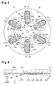
- Parts of the circular thin plate are cut out to form a plurality of elongated extended portions in the suction valve plate 25 that extend radially outward in the radial direction from the center. Each extended portion forms a suction reed valve 25a that closes the suction port 23a.
- the suction port 23a is circular when viewed from above.
- the seating surface 270 includes annular grooves 272 entirely surrounding the suction ports 23a, that is, entirely surrounding opening edges.
- annular regions arranged between the suction ports 23a and the grooves 272 define flat seal surfaces 271 (also referred to as eyeglass portions).
- the seating surface 270 comes into contact with the suction reed valves 25a when the suction reed valves 25a close.
- the region sandwiching the grooves 272 with the suction ports 23a defines a reference surface 273, which is flush with the seal surfaces 271.
- each suction reed valve 25a includes a fixed portion 251, which is fixed to the reference surface 273, a base portion 252, which extends from the fixed portion 251 in a first direction D1 and is movable toward and away from the reference surface 273, and a valve portion 253, which extends from the base portion 252 in the first direction D1 to open and close the suction port 23a.
- the valve portion 253 in the valve portion 253, the surface that comes into close contact with the seal surface 271 defines a flat shutting surface 253a.
- the first direction D1 is parallel to the seating surface 270 and extends outward in the radial direction of the drive shaft 11.
- the base portion 252 when viewing the base portion 252 and the valve portion 253 from above, the base portion 252 is rectangular and elongated in the first direction D1.
- a rim 253b of the valve portion 253 is arcuate and concentric with the suction port 23a and the groove 272.
- the rim 253b has a diameter that is slightly larger than a length of a short side of the base portion 252, larger than that of the seal surface 271 and smaller than that of the outermost contour of the groove 272. That is, the rim 253b is arranged at a position corresponding to the groove 272.
- the protrusions 273a are formed in a region separated from the seal surface 271.
- a knurling process is performed to form the protrusions 273a. This forms fine ridges, which project from the reference surface 273, and fine valleys, which are recessed in the reference surface 273, in a grid-shaped manner.
- the protrusions 273a extend from the two sides of the base portion 252 over a wider area than the base portion 252. Further, the protrusions extend in the first direction D1 to the vicinity of the groove 272.
- the height difference ⁇ between the reference surface 273 and the fine ridges is in the range of ten micrometers to several tens of micrometers although this depends on the compressor size of the compressor or the reed valve size.
- a discharge valve plate 29 and a retainer plate 31 are fixed to the valve plate 27.
- Discharge ports 23b are formed in the suction valve plate 25 and the valve plate 27 to communicate the discharge chamber 5b and the compression chambers 24.
- the discharge valve plate 29 includes discharge reed valves 29a, which open and close the discharge ports 23b.
- the retainer plate 31 includes a retainer 31 a that restricts the lift length (open amount) of the discharge reed valves 29a.
- the drive shaft 11 is rotated and driven so that the lug plate 13 and swash plate 17 rotate integrally with the drive shaft 11 and reciprocate each piston 21 in the corresponding cylinder bore 1a with a stroke that is in accordance with the inclination angle of the swash plate 17.
- refrigerant is drawn from the suction chamber 5a into each compression chamber 24 and discharged into the discharge chamber 5b.
- Atomized lubrication oil is suspended in the refrigerant compressed by the compressor.
- the lubrication oil collects on and thereby suppresses wear of moving components such as the pistons 21, the shoes 33a and 33b, and the swash plate 17.
- the lubrication oil also collects on the surfaces of the seating surface 270, the suction reed valves 25a, and the discharge reed valves 29a and in the grooves 272.
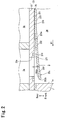
- each protrusion 273a separates the base portion 252 from the reference surface 273 as shown in Fig. 2 .
- the base portion 252 is part of the suction valve plate 25, which is formed by an elastically deformable circular thin plate as described above.
- the part near the fixed portion 251 is in close contact with the reference surface 273.
- other parts of the base portion 252 are lifted by the protrusions 273a and extend in the first direction D1 so as to form a gap W with the reference surface 273.
- the suction reed valve 25a readily opens when the pressure of the compression chamber 24 becomes lower than the pressure of the suction chamber 5a.
- an opening delay of the suction reed valve 25a subtly occurs, sudden opening of the suction reed valve 25a at a delayed timing is suppressed, and vibration of the suction reed valve 25a is reduced. In this manner, the compressor reduces suction pulsation and consequently improves quietness.
- the base portion 252 moves toward the reference surface 273 as shown in Fig. 4 . More specifically, the base portion 252 curves along the protrusions 273a and extends in the first direction D1, while maintaining the height difference ⁇ from the reference surface 273. As the protrusions 273a terminate in the vicinity of the groove 272, the base portion 252 is elastically deformed and curved back to the reference surface 273 so that the shutting surface 253a of the valve portion 253 comes into close contact with the seal surface 271.
- the shutting surface 253a and the seal surface 271 are flat and not roughened.
- the lubrication oil suspended in the refrigerant gas remains in the groove 272, and the rim 253b of the valve portion 253 is arranged at a position corresponding to the groove 272.
- the lubrication oil in the groove 272 contacts the rim 253b of the valve portion 253 thereby ensuring that the space between the shutting surface 253a and the seal surface 271 is sealed.
- the compressor as compared with the compressor of patent document 1, maintains high compression efficiency and realizes a high cooling capability.
- the protrusion 273a is arranged integrally with the seating surface 273. Since the number of components does not increase, there is no increase in costs.
- the lubrication oil collected in the groove 272 ensures that the space between the seal surface 271 and the shutting surface 253a is sealed. This improves the compression efficiency.
- a knurling process is performed to ensure that the height difference ⁇ between the base portion 252 and the seating surface 270 is obtained with small variations. Further, the protrusions 273a are easy to form and thereby suppress rises in the manufacturing cost.
- the area of contact between the rim 253b of the valve portion 253 and the lubrication oil in the groove 272 be optimized by properly setting the width of the groove 272 or the extended amount of the rim 253b from the seal surface 271.
- the structure that supports the suction reed valves 25a with the plurality of protrusions 273a reduces concentrated stress at the location where the suction reed valve 25a is supported in comparison with a structure that supports the suction reed valve with a single protrusion.
- pulsation can be reduced while maintaining high compression efficiency. Further, costs may be lowered, and stress concentration at the suction reed valves 25a can be reduced.
- Figs. 7 and 8 illustrate main parts of a compressor according to a second embodiment of the present invention.
- the discharge ports 23b are formed in the suction valve plate 25 and the valve plate 27 to communicate the discharge chamber 5b and the compression chambers 24.
- the discharge valve plate 29 includes the discharge reed valves 29a, which open and close the discharge ports 23b.
- the discharge valve plate 29 is formed from an elastically deformable thin plate, and the discharge reed valves 29a extend radially.
- the discharge port 23b is circular when viewed from above.
- the surface of the valve plate 27 facing the discharge chamber 5b, that is, the surface facing the discharge valve plate 29, defines a seating surface 275.
- the seating surface 275 includes annular grooves 277 entirely surrounding the discharge ports 23b, that is, entirely surrounding opening edges.
- annular regions arranged between the discharge ports 23b and the grooves 277 define flat seal surfaces 276 (also referred to as eyeglass portions).
- the region sandwiching the grooves 277 with the discharge ports 23b defines a reference surface 278, which is flush with the seal surfaces 276.
- each discharge reed valve 29a includes a fixed portion 291, which is fixed to the reference surface 278, a base portion 292, which extends from the fixed portion 291 in a first direction D1 and is movable toward and away from the reference surface 278, and a valve portion 293, which extends from the base portion 292 in the first direction D1 to open and close the discharge port 23b.
- the valve portion 293, the surface that comes into close contact with the seal surface 276 defines a flat shutting surface 293a.
- the first direction D1 is parallel to the seating surface 275 and extends outward in the radial direction of the drive shaft 11.
- the base portion 292 when viewing the base portion 292 and the valve portion 293 from above, the base portion 292 is rectangular and elongated in the first direction D1.
- a rim 293b of the valve portion 293 is arcuate and concentric with the discharge port 23b and the groove 277.
- the rim 293b has a diameter that is slightly larger than a length of a short side of the base portion 292, larger than that of the seal surface 276 and smaller than that of the outermost contour of the groove 277. That is, the rim 293b is arranged at a position corresponding to the groove 277.
- the reference surface 278, specifically, the region of the reference surface 278 facing the base portion 292 includes a plurality of protrusions 278a, which protrude toward the discharge chamber 5b.
- the protrusions 278a are similar to the protrusions 273a shown in Fig. 6 .
- the protrusions 278a are formed in a region separated from the seal surfaces 276. The remaining structure is the same as the first embodiment.
- the compressor of the present embodiment has the advantages described below.
- (1) denotes a period during which the compression is performing a suction stroke or a compression stroke.
- the pressure of the discharge chamber 5b is higher than the pressure of the compression chamber 24.
- the valve portion 293 of the discharge reed valve 29a closes the discharge port 23b and is elastically deformed slightly. In this state, the shutting surface 293a is in close contact with the seal surface 276, and a reverse flow of refrigerant gas from the discharge chamber 5b to the compression chamber 24 is not produced.
- valve portion 293 opens the discharge port 23b by a greater amount in a state restricted by the retainer 31 a.
- Fig. 15 is an enlarged diagram showing part of Fig. 1 , specifically, changes in the pressure of the compression chamber 24 during the discharge stroke.
- the solid line indicates pressure changes in a compressor that does not include the protrusions 273a
- the broken line indicates pressure changes in the compressor of the second embodiment.
- the compressor of the second embodiment can reduce discharge pulsation, while maintaining high compression efficiency. Further, the compressor can lower costs and reduce stress concentration at the discharge reed valves 29a. Other advantages are the same as the first embodiment.
- a formation range of the plurality of protrusions 273a is changed from the first embodiment. More specifically, a plurality of protrusions 273b in the third embodiment are formed continuously in a region extending from the vicinity of the discharge port 23b to a rim 272a of the groove 272 on the reference surface 273 in the first direction D1. The protrusions 273b are continuous with the rim 272a of the groove 272.
- the surface of the valve plate 27 facing the discharge chamber 5b that is, the surface facing the discharge valve plate 29, defines the seating surface 275.
- the seating surface 275 includes annular grooves 277 entirely surrounding the discharge ports 23b, that is, entirely surrounding opening edges.
- the protrusions 273b are separated from the region of the reference surface 273 located at the opposite side of the grooves 277.
- the protrusions 273b extend from the two sides of the base portion 252 over a wider area than the base portions 252.
- the remaining structure is the same as the compressor of the first embodiment.
- same reference characters are given to those components that are the same as the corresponding components of the compressor in the first embodiment. Such components are not described in detail.
- the base portion 252 elastically deforms along the protrusion 273b. This ensures that the height difference ⁇ is obtained between the base portion 252 and the reference surface 273.
- the protrusions 273b are formed continuously in the region extending from the vicinity of the discharge port 23b to the rim 272a of the groove 272 on the reference surface 273. This makes it difficult for an oil film to form between part of the periphery of the rim 272a of the groove 272 and the suction reed valve 25a. An oil film is apt to being broken by the protrusions 273b formed continuously with the groove 272 and the rim 272a of groove 272. Thus, in comparison with the compressor of the first embodiment, in the compressor of the present embodiment, it is further difficult for an adhesion force to act between the suction reed valve 25a and the seating surface 270.
- the compressor of the present embodiment maintains high compression efficiency and, consequently, realizes a high cooling capability.
- the protrusions 273b are separated from the region of the reference surface 273 located at the opposite side of the grooves 277, which are formed around the discharge ports 23b.
- the rigidity of the valve plate 27 is lower than the surrounding of the groove 277. Accordingly, when the protrusions 273b are formed in the valve plate 27, deformation is suppressed around the discharge ports 23b.
- Other advantages are the same as the first embodiment.
- a suction port 23c includes two straight portions 231, which extend in a direction orthogonal to the first direction D1 of a suction reed valve 25c, and two arcuate portions 232, which connect the ends of the two straight portions 231.
- a seal surface 371 includes two straight portions 371a and two arcuate portions 371 b, which connect the ends of the two straight portions 371a, so as to surround the suction port 23c.
- a groove 372 includes two straight portions 372a and two arcuate portions 372b, which connect the ends of the two straight portions 372a, so as to surround the seal surface 371.
- the suction reed valve 25c includes a valve portion 353 having a shape corresponding to the shapes of the suction port 23c and the seal surface 371.
- a plurality of protrusions 273c are formed continuously on the reference surface 270 of the valve plate 27 in a region extending from a position facing a boundary position 250 of the fixed portion 251 and the base portion 252 to a rim 372c of the groove 372 surrounding the suction port 23c. That is, the protrusions 273c are formed to face the entire base portion 252.
- the protrusions 273c are formed to be continuous with the rim 372c along the one of the two straight portions 372a that is located closer to the base portion 252 of the groove 372. As shown in Fig.
- the protrusions 273c are formed to be separated from the region of the reference surface 270 located at the opposite side of the groove 277 in the same manner as the compressor of the third embodiment.
- the remaining structure is the same as the compressor of the third embodiment.
- same reference characters are given to those components that are the same as the corresponding components of the compressor in the third embodiment. Such components are not described in detail.
- the protrusions 273c are formed facing the entire base portion 252.
- an adhesion force to act between the suction reed valve 25c and the seating surface 270.
- an opening delay of the suction reed valve 25c subtly occurs.
- sudden changes in the open amount of the suction reed valve 25c and vibration of the suction reed valve 25c are reduced.
- the compressor of the present embodiment maintains high compression efficiency and, consequently, realizes a high cooling capability.
- Other advantages are the same as the first and third embodiments.
- a plurality of protrusions 50a are formed entirely around the grooves 272 and 277.
- the protrusions 50a separate the seal surface 51 and a shutting surface 43a.
- Fig. 19 shows a state in which the pressure is the same in the compression chamber 24 and the suction chamber 5a.
- the shutting surface 43a of a valve portion 433 comes into close contact with the seal surface 51.
- the remaining structure is the same as the compressors of the first and second embodiments.
- same reference characters are given to those components that are the same as the corresponding components of the compressor in the first and second embodiments. Such components are not described in detail.
- the protrusions 50a around the grooves 272 and 277 decrease the area of contact between the valve portion 433 of a reed valve 43 and the reference surface 50.
- the suction port 23a and discharge port 23b easily open.
- a plurality of protrusions 252a are formed on the suction reed valve 25a.
- the protrusions 252a are formed to extend to a position facing the rim 272a of the groove 272.
- the remaining structure is the same as the compressor of the third embodiment.
- same reference characters are given to those components that are the same as the corresponding components of the compressor in the third embodiment. Such components are not described in detail.
- the protrusions 252a are formed at a location facing the rim 272a of the grooves 272. This makes it difficult for an oil film to form between part of the rim 272a of the groove 272 and the suction reed valve 25a. An oil film is apt to being broken by the protrusions 252a formed at a position facing the groove 272 and the rim 272a of the groove 272. Other advantages are the same as the first embodiment.
- the protrusions 273a, 278a, 50a, and 252 are formed through a knurling process but there is no such limitation.
- the protrusions 273a, 278a, 50a, and 252 may be formed through a blasting process or a laser process.
- the present invention is described with the first to sixth embodiments.
- the present invention is not limited to the first to sixth embodiments and may be applied without departing from the scope of the invention.
- W gap; 5a: suction chamber; 5b: discharge chamber; 23a and 23c: suction port; 24: compression chamber; 25a and 25c: suction reed valve; 27: partition wall (valve plate); 29a: discharge reed valve; 43: reed valve; 50, 270, and 275: seating surface; 250: boundary position; 251 and 291: fixed portion; 252 and 292: base portion; 253, 293, and 353: valve portion; 253a and 293a: shutting surface; 271, 276, and 371: seal surface; 273 and 50: reference surface, 272, 277, and 372: groove; 272a and 372c: rim; 273a, 278a, 50a, 252a: plurality of protrusions.
Landscapes
- Engineering & Computer Science (AREA)
- General Engineering & Computer Science (AREA)
- Mechanical Engineering (AREA)
- Compressor (AREA)
- Applications Or Details Of Rotary Compressors (AREA)
Abstract
Description
- The present invention relates to a compressor.
- A typical compressor includes a partition wall arranged between a compression chamber and a suction chamber. A suction port extends through the partition wall thereby allowing for communication of the compression chamber and the suction chamber. A suction reed valve opens and closes the suction port. The partition wall includes a seating surface. The suction reed valve comes into contact with the seating surface when closing the suction port. The suction reed valve includes a fixed portion, which is fixed to the partition wall, a base portion, which extends from the fixed portion along the partition wall and is movable toward and away from the partition wall, and a valve portion, which extends from the base portion along the partition wall to open and close the suction port.
- When the pressure of the compression chamber increases and becomes higher than the pressure of the suction chamber, the suction reed valve closes the suction port as the base portion and valve portion come into contact with the seating surface. When the pressure of the compression chamber becomes lower than the pressure of the suction chamber, the suction reed valve opens the suction port as the base portion and valve portion move away from the seating surface. However, in an actual compressor that uses refrigerant gas including lubrication oil, a valve opening resistance (e.g., adhesion force produced between the base portion and valve portion and the seating surface) acts on the suction reed valve. Thus, even when the pressure of the compression chamber decreases from the pressure of the suction chamber, a state in which the suction port does not readily open, that is, an opening delay of the suction reed valve, is apt to occur. This is one factor that causes suction pulsation.
- For the same reason, suction pulsation also occurs in a compressor including a discharge port, which extends through a partition wall between a compression chamber and a discharge chamber, and a discharge reed valve, which opens and closes the discharge port.
- To cope with this problem, in a compressor disclosed in
patent document 1, either one of a seating surface and a contact surface of a suction reed valve (base portion and valve portion), which contacts the seat surface, is roughened. This decreases the valve opening resistance of the suction reed valve and reduces suction pulsation caused by the valve opening resistance. - Further, in a compressor disclosed in
patent document 2, a seat member is arranged between a seating surface and a base portion of a suction reed valve. This decreases the valve opening resistance of the suction reed valve and reduces suction pulsation caused by the valve opening resistance. - In a compressor of
patent document 3, a protrusion that projects toward a suction reed valve is arranged in a portion around a suction hole on a seating surface. This decreases the valve opening resistance of the suction reed valve and reduces suction pulsation caused by the valve opening resistance. -
- Patent Document 1: Japanese Laid-Open Patent Publication No.
2000-54961 - Patent Document 2: Japanese Patent No.
4395400 - Patent Document 3: Japanese Laid-Open Patent Publication No.
2005-42695 - However, in the compressors of
documents 1 to 3, it is difficult to reduce pulsation while maintaining high compression efficiency and lowering costs. - More specifically, if either one of a seating surface and a contact surface of a suction reed valve (or discharge reed valve) is roughened to reduce pulsation, the roughened surface decreases the adhesiveness between the suction reed valve (or discharge reed valve) and the seating surface when the suction reed valve (or discharge reed valve) closes the suction port (or discharge port). Thus, sealing defects are apt to occur. In such a case, refrigerant gas is apt to leak from the compression chamber to the suction chamber (or from the discharge chamber to the compression chamber) thereby making it difficult to maintain a high compression efficiency.
- Accordingly, as disclosed in paragraph 0027 of Japanese Patent No.
3326909 - However, the compressor of Japanese Patent No.
3326909 - Further, when employing the seat member, which is discrete from the reed valve, like in
document 2, the number of components increases. Thus, a rise in costs cannot be avoided. Further, in the structure shown inFig. 5 ofdocument 3, the reed suction valve opening and closing actions are performed using the protrusion as a fulcrum. In such a structure, stress concentrates at portions of contact between the protrusion and the reed valve. - It is an object of the present invention to provide a compressor that reduces pulsation and avoids the concentration of stress at a reed valve while maintaining high compression efficiency.
- To achieve the above object, one aspect of the present invention provides a compressor including a partition wall, a reed valve, and a seating surface. The partition wall is arranged between a compression chamber and a suction chamber or discharge chamber. The partition wall includes a port that communicates the compression chamber to the suction chamber or the discharge chamber. The reed valve is flexible. The reed valve can open and close the port. The reed valve includes a fixed portion, which is fixed to the partition wall, a base portion, which extends from the fixed portion along the partition wall and is movable toward and away from the partition wall, and a valve portion, which extends from the base portion further along the partition wall and opens and closes the port. The seating surface is formed on the partition wall and comes into contact with the reed valve when the reed valve closes the port. The seating surface includes a flat seal surface, which surrounds the port, and a groove, which surrounds the seal surface. The valve portion includes a flat shutting surface that comes into close contact with the seal surface and closes the port. The seating surface or the reed valve includes a plurality of protrusions that separate the seal surface and the shutting surface when the pressure of the compression chamber is equal to the pressure of the suction chamber or the discharge chamber. The protrusions are formed at locations separated from the seal surface and the shutting surface.
- In the compressor of the present invention, when the pressure of the compression chamber is equal to the pressure of the suction chamber or the discharge chamber, the protrusions separate the seal surface and the shutting surface. Thus, if the port is a suction port, the reed valve easily opens the suction port when the pressure of the compression chamber becomes lower than the pressure of the suction chamber. As a result, an opening delay subtly of the reed valve subtly occurs, and suction pulsation can be reduced. If the port is a discharge port, due to the same effect, the reed valve easily opens the discharge port and discharge pulsation can be reduced. A case in which the pressure of the compression chamber becomes equal to the pressure of the suction chamber and a case in which the pressure of the compression chamber becomes equal to the pressure of the discharge chamber refers to a state in which there is no pressure difference between the compression chamber and the suction chamber or a state in which there is no pressure difference between the compression chamber and the discharge chamber when the compressor is operating and a state in which a pressure difference between the compression chamber and the suction chamber is eliminated or a state in which a pressure difference between the compression chamber and the discharge chamber is eliminated when the compressor stops operating.
- Further, if the port is a suction port, when the pressure of the compression chamber becomes higher than the pressure of the suction chamber in the compressor, the reed valve closes the suction port as the shutting surface of the valve portion comes into close contact with the seal surface of the seating surface. On the other hand, if the port is a discharge port, when the pressure of the compression chamber becomes lower than the pressure of the discharge chamber, the reed valve closes the discharge port as the shutting surface of the valve portion comes into close contact with the seal surface of the seating surface, due to the same operation. The shutting surface and the seal surface are not roughened. This ensures that the port is closed when the shutting surface comes into close contact with the seal surface. Thus, the compressor can maintain high compression efficiency and realize a high cooling capability
- Additionally, the plurality of protrusions obtains a gap between the reed valve and the seating surface when the reed valve moves away from the seating surface. Thus, the reed valve and seating surface do not come into close contact, and an adhesion force does not act between the reed valve and the seating surface. As a result, an opening delay of the reed valve subtly occurs, sudden changes in the valve open amount of the port and vibration of the reed valve are reduced. In this manner, the compressor reduces suction pulsation and consequently improves the quietness.
- Moreover, in comparison with
patent document 3, the plurality of protrusions supports the valve body. Accordingly, concentrated stress is reduced at a location where the valve body is supported compared topatent document 3 that supports the valve body with a single protrusion. - In this manner, the compressor according to the present invention reduces pulsation and avoids the concentration of stress at a valve body while maintaining high compression efficiency.
- Preferably, the protrusions are formed continuously with a rim of the groove on the seating surface.
- The protrusions are formed continuously with the rim of the groove. Thus, in comparison with
patent document 3, it becomes difficult for an oil film to form between the periphery of the rim of the groove and the reed valve. The protrusions, which are formed continuously with the groove and the rim of the groove, act to easily break an oil film. - Preferably, the protrusions are formed in a region facing the base portion on the seating surface.
- Preferably, the protrusions are formed in at least a region facing a rim of the groove on the reed valve.
- The protrusions are formed in at least a region facing a rim of the groove on the reed valve. Thus, in comparison with
patent document 3, it becomes difficult for an oil film to form between the periphery of the rim of the groove and the reed valve. The groove and the protrusions, which are formed at a location facing the rim of the groove, act to easily break an oil film. - Preferably, the protrusions are formed on the base portion.
- Preferably, the protrusions are formed through any one of a knurling process, a blasting process, and a laser process.
- Any one of a knurling process, a blasting process, and a laser process ensures that a gap having small variations is obtained between the reed valve and the seating surface. Further, the plurality of protrusions can be easily formed by any one of the knurling process, blasting process, and laser process. Thus, the compressor suppresses rises in manufacturing cost.
-
-
Fig. 1 is a vertical cross-sectional view of a compressor according to a first embodiment of the present invention. -
Fig. 2 is an enlarged cross-sectional view showing the compressor ofFig. 1 in a state in which a suction reed valve opens a suction port. -
Fig. 3 is a plan view of the compressor ofFig. 1 showing a valve plate and a suction valve plate, which includes a plurality of suction reed valves. -
Fig. 4 is an enlarged cross-sectional view showing the compressor ofFig. 1 in a state in which the suction reed valve closes the suction port. -
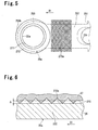
Fig. 5 is an enlarged plan view of the compressor ofFig. 1 showing a suction reed valve and a suction port from the direction of arrow V inFig. 4 . -
Fig. 6 is an enlarged cross-sectional view of the compressor ofFig. 1 showing protrusions, which are formed on a reference surface, and a base portion of the suction reed valve. -
Fig. 7 is an enlarged cross-sectional view of a compressor according to a second embodiment of the present invention showing a state in which a discharge reed valve opens a discharge port. -
Fig. 8 is a plan view of the compressor ofFig. 7 showing a valve plate and a discharge valve plate, which includes a plurality of discharge reed valves. -
Fig. 9 is an enlarged cross-sectional view of the compressor of the second embodiment showing a state in which the discharge reed valve closes the discharge port. -
Fig. 10 is an enlarged plan view of the compressor of the second embodiment showing a discharge reed valve and a discharge port from the direction of arrow V inFig. 9 . -
Fig. 11 is an enlarged cross-sectional view of the compressor of the second embodiment showing a state in which the discharge reed valve slightly opens the discharge port. -
Fig. 12 is an enlarged cross-sectional view of the compressor of the second embodiment showing a state in which the discharge reed valve opens the discharge port by a small amount. -
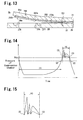
Fig. 13 is an enlarged cross-sectional view of the compressor of the second embodiment showing a state in which the discharge reed valve opens the discharge port by a large amount. -
Fig. 14 is a graph showing the relationship of time and the pressure of the compression chamber in the compressor of the second embodiment. -
Fig. 15 is an enlarged view ofFig. 14 . -
Fig. 16 is an enlarged cross-sectional view of a compressor according to a third embodiment showing a state in which a suction reed valve closes a suction port. -
Fig. 17 is an enlarged plan view of the compressor of the third embodiment showing the suction reed valve, the suction port, and a discharge port. -
Fig. 18 is an enlarged plan view of a compressor according to a fourth embodiment showing a suction reed valve, a suction port, and a discharge port. -
Fig. 19 is an enlarged cross-sectional view of a compressor according to a fifth embodiment showing a state in which a reed valve opens a port. -
Fig. 20 is an enlarged cross-sectional view of a compressor according to a sixth embodiment showing a state in which a suction reed valve closes a suction port. - First to sixth embodiments of the present invention will now be described with reference to the drawings. The compressors of the first to sixth embodiments are variable displacement swash plate type compressors.
Fig. 1 shows the front to rear direction of a compressor in which the left side defines the front side of the compressor and the right side defines the rear side of the compressor. Further, the front to rear directions in the drawings all correspond toFig. 1 . - Referring to
Fig. 1 , a housing of the compressor in the first embodiment includes acylinder block 1, afront housing member 3, which is joined with the front end of thecylinder block 1, and arear housing member 5, which is joined with the rear end of thecylinder block 1 with avalve unit 23 arranged in between. A plurality ofbolts 7 fasten thecylinder block 1, thefront housing member 3, and therear housing member 5 to one another. Thecylinder block 1 includes a plurality of cylinder bores 1a. The cylinder bores 1a are arranged at equal angular intervals along the same circle and extend parallel to one another along the axis of thecylinder block 1. Thecylinder block 1 and thefront housing member 3 form a crankchamber 9. Therear housing member 5 includes asuction chamber 5a, which is located at an outer part in the radial direction, and adischarge chamber 5b, which is located at a central part in the radial direction. - The
front housing member 3 includes ashaft hole 3a, and thecylinder block 1 includes ashaft hole 1 b. Adrive shaft 11 is inserted in the shaft holes 3a and 1 b. Thedrive shaft 11 is rotatably supported byradial bearing front housing member 3 and thecylinder block 1. A pulley or electromagnetic clutch (not shown) is arranged on thedrive shaft 11. A belt (not shown), which is driven by an engine or motor of a vehicle engine, runs over the pulley or a pulley of the electromagnetic clutch. - A
lug plate 13 is fixed to adrive shaft 11 in thecrank chamber 9. Athrust bearing 15 is arranged between thelug plate 13 and thefront housing member 3. Thedrive shaft 11 extends through aswash plate 17 and supports theswash plate 17. Alink mechanism 19 couples theswash plate 17 to thelug plate 13 so that theswash plate 17 is inclinable relative to thelug plate 13. - A
piston 21 is accommodated in each cylinder bore 1a and movable in a reciprocating manner. As shown inFig. 2 , thevalve unit 23 includes asuction valve plate 25 and avalve plate 27, which contacts thesuction valve plate 25. Thevalve plate 27 is one example of a partition wall of the present invention. - As shown in
Fig. 1 , front andrear shoes swash plate 17 and eachpiston 21. Each pair ofshoes swash plate 17 to the reciprocating motion of thepiston 21. - Although not shown in the drawings, a bleeding passage connects the
crank chamber 9 and thesuction chamber 5a, and a gas supplying passage connects thecrank chamber 9 and thedischarge chamber 5b. A displacement control valve is arranged in the gas supplying passage. The displacement control valve changes the open amount of the gas supplying passage in accordance with the suction pressure. Further, although not shown in the drawings, thedischarge chamber 5b is connected by a pipe to a condenser. The condenser is connected by a pipe via an expansion valve to an evaporator. The evaporator is connected by a pipe to thesuction chamber 5a of the compressor. The cylinder bores 1a, thepistons 21, and thevalve unit 23form compression chambers 24. - As shown in
Figs. 2 and3 , thevalve plate 27 includessuction ports 23a that communicate thesuction chamber 5a and thecompression chambers 24. Thesuction valve plate 25 includessuction reed valves 25a that open and close thesuction ports 23a. Referring toFig. 3 , in the present embodiment, thesuction valve plate 25 is formed by an elastically deformable circular thin plate. InFig. 3 , the front of the plane of the drawing corresponds to the front side of the compressor, and the rear of the plane of the drawing corresponds to the rear side of the compressor. The cylinder bores 1a are located toward the front of the plane of the drawing from thesuction valve plate 25 and shown by the double-dashed lines. Parts of the circular thin plate are cut out to form a plurality of elongated extended portions in thesuction valve plate 25 that extend radially outward in the radial direction from the center. Each extended portion forms asuction reed valve 25a that closes thesuction port 23a. - Referring to
Figs. 3 to 5 , thesuction port 23a is circular when viewed from above. The surface of thevalve plate 27 facing thecompression chambers 24, that is, the surface facing the suction valve plate 25A, defines aseating surface 270. Theseating surface 270 includesannular grooves 272 entirely surrounding thesuction ports 23a, that is, entirely surrounding opening edges. In theseating surface 270, annular regions arranged between thesuction ports 23a and thegrooves 272 define flat seal surfaces 271 (also referred to as eyeglass portions). Theseating surface 270 comes into contact with thesuction reed valves 25a when thesuction reed valves 25a close. - Referring to
Figs. 2 and4 , in theseating surface 270, the region sandwiching thegrooves 272 with thesuction ports 23a defines areference surface 273, which is flush with the seal surfaces 271. - As shown in
Figs. 2 to 5 , eachsuction reed valve 25a includes a fixedportion 251, which is fixed to thereference surface 273, abase portion 252, which extends from the fixedportion 251 in a first direction D1 and is movable toward and away from thereference surface 273, and avalve portion 253, which extends from thebase portion 252 in the first direction D1 to open and close thesuction port 23a. As shown inFig. 4 , in thevalve portion 253, the surface that comes into close contact with theseal surface 271 defines a flat shuttingsurface 253a. In the present embodiment, the first direction D1 is parallel to theseating surface 270 and extends outward in the radial direction of thedrive shaft 11. - Referring to
Fig. 5 , when viewing thebase portion 252 and thevalve portion 253 from above, thebase portion 252 is rectangular and elongated in the first direction D1. Arim 253b of thevalve portion 253 is arcuate and concentric with thesuction port 23a and thegroove 272. Therim 253b has a diameter that is slightly larger than a length of a short side of thebase portion 252, larger than that of theseal surface 271 and smaller than that of the outermost contour of thegroove 272. That is, therim 253b is arranged at a position corresponding to thegroove 272. - Referring to
Figs. 2 to 5 , thereference surface 273, specifically, the regions of thereference surface 273 facing thebase portions 252, includes a plurality of protrusions 273a, which protrude toward thecompression chambers 24. Theprotrusions 273a are formed in a region separated from theseal surface 271. Referring toFigs. 5 and 6 , in the present embodiment, a knurling process is performed to form theprotrusions 273a. This forms fine ridges, which project from thereference surface 273, and fine valleys, which are recessed in thereference surface 273, in a grid-shaped manner. - The
protrusions 273a extend from the two sides of thebase portion 252 over a wider area than thebase portion 252. Further, the protrusions extend in the first direction D1 to the vicinity of thegroove 272. Preferably, the height difference Δ between thereference surface 273 and the fine ridges is in the range of ten micrometers to several tens of micrometers although this depends on the compressor size of the compressor or the reed valve size. - Referring to
Fig. 1 , adischarge valve plate 29 and aretainer plate 31 are fixed to thevalve plate 27.Discharge ports 23b are formed in thesuction valve plate 25 and thevalve plate 27 to communicate thedischarge chamber 5b and thecompression chambers 24. Thedischarge valve plate 29 includesdischarge reed valves 29a, which open and close thedischarge ports 23b. Theretainer plate 31 includes aretainer 31 a that restricts the lift length (open amount) of thedischarge reed valves 29a. - In the compressor formed as described above, the
drive shaft 11 is rotated and driven so that thelug plate 13 andswash plate 17 rotate integrally with thedrive shaft 11 and reciprocate eachpiston 21 in the corresponding cylinder bore 1a with a stroke that is in accordance with the inclination angle of theswash plate 17. As a result, refrigerant is drawn from thesuction chamber 5a into eachcompression chamber 24 and discharged into thedischarge chamber 5b. Atomized lubrication oil is suspended in the refrigerant compressed by the compressor. The lubrication oil collects on and thereby suppresses wear of moving components such as thepistons 21, theshoes swash plate 17. The lubrication oil also collects on the surfaces of theseating surface 270, thesuction reed valves 25a, and thedischarge reed valves 29a and in thegrooves 272. - In this state, when the pressure of the
compression chamber 24 is equal to or lower than the pressure of thesuction chamber 5a, eachprotrusion 273a separates thebase portion 252 from thereference surface 273 as shown inFig. 2 . Thebase portion 252 is part of thesuction valve plate 25, which is formed by an elastically deformable circular thin plate as described above. Thus, in thebase portion 252, the part near the fixedportion 251 is in close contact with thereference surface 273. However, other parts of thebase portion 252 are lifted by theprotrusions 273a and extend in the first direction D1 so as to form a gap W with thereference surface 273. Thus, close contact between thebase portion 252 and thereference surface 273 is avoided making it difficult for an adhesion force to act between thebase portion 252 and thereference surface 273. This separates theseal surface 271 and the shuttingsurface 253a. As a result, thesuction reed valve 25a readily opens when the pressure of thecompression chamber 24 becomes lower than the pressure of thesuction chamber 5a. Thus, an opening delay of thesuction reed valve 25a subtly occurs, sudden opening of thesuction reed valve 25a at a delayed timing is suppressed, and vibration of thesuction reed valve 25a is reduced. In this manner, the compressor reduces suction pulsation and consequently improves quietness. - When the pressure of the
compression chamber 24 increases and becomes higher than the pressure of thesuction chamber 5a, thebase portion 252 moves toward thereference surface 273 as shown inFig. 4 . More specifically, thebase portion 252 curves along theprotrusions 273a and extends in the first direction D1, while maintaining the height difference Δ from thereference surface 273. As theprotrusions 273a terminate in the vicinity of thegroove 272, thebase portion 252 is elastically deformed and curved back to thereference surface 273 so that the shuttingsurface 253a of thevalve portion 253 comes into close contact with theseal surface 271. The shuttingsurface 253a and theseal surface 271 are flat and not roughened. This ensures that the shuttingsurface 253a comes into close contact with theseal surface 271 and ensures that thesuction port 23a is closed. Further, the lubrication oil suspended in the refrigerant gas remains in thegroove 272, and therim 253b of thevalve portion 253 is arranged at a position corresponding to thegroove 272. Thus, when thevalve portion 253 closes thesuction port 23a, the lubrication oil in thegroove 272 contacts therim 253b of thevalve portion 253 thereby ensuring that the space between the shuttingsurface 253a and theseal surface 271 is sealed. As a result, the compressor, as compared with the compressor ofpatent document 1, maintains high compression efficiency and realizes a high cooling capability. - Further, in the compressor of the present embodiment, the
protrusion 273a is arranged integrally with theseating surface 273. Since the number of components does not increase, there is no increase in costs. - Additionally, in the compressor of the present embodiment, when the
suction reed valve 25a closes thesuction port 23a, the lubrication oil collected in thegroove 272 ensures that the space between theseal surface 271 and the shuttingsurface 253a is sealed. This improves the compression efficiency. - Moreover, in the compressor of the present embodiment, a knurling process is performed to ensure that the height difference Δ between the
base portion 252 and theseating surface 270 is obtained with small variations. Further, theprotrusions 273a are easy to form and thereby suppress rises in the manufacturing cost. - When the sealing of the space between the shutting
surface 253a and theseal surface 271 with the lubrication oil in thegroove 272 becomes too strong, an opening delay of thevalve portion 253 is apt to occur. It is thus preferable that the area of contact between therim 253b of thevalve portion 253 and the lubrication oil in thegroove 272 be optimized by properly setting the width of thegroove 272 or the extended amount of therim 253b from theseal surface 271. - Further, the structure that supports the
suction reed valves 25a with the plurality ofprotrusions 273a reduces concentrated stress at the location where thesuction reed valve 25a is supported in comparison with a structure that supports the suction reed valve with a single protrusion. - Thus, in the compressor of the present embodiment, pulsation can be reduced while maintaining high compression efficiency. Further, costs may be lowered, and stress concentration at the
suction reed valves 25a can be reduced. -
Figs. 7 and8 illustrate main parts of a compressor according to a second embodiment of the present invention. - As shown in
Figs. 7 and8 , thedischarge ports 23b are formed in thesuction valve plate 25 and thevalve plate 27 to communicate thedischarge chamber 5b and thecompression chambers 24. Thedischarge valve plate 29 includes thedischarge reed valves 29a, which open and close thedischarge ports 23b. In the present embodiment, referring toFig. 8 , thedischarge valve plate 29 is formed from an elastically deformable thin plate, and thedischarge reed valves 29a extend radially. - Referring to
Figs. 8 to 10 , thedischarge port 23b is circular when viewed from above. The surface of thevalve plate 27 facing thedischarge chamber 5b, that is, the surface facing thedischarge valve plate 29, defines aseating surface 275. Theseating surface 275 includesannular grooves 277 entirely surrounding thedischarge ports 23b, that is, entirely surrounding opening edges. In theseating surface 275, annular regions arranged between thedischarge ports 23b and thegrooves 277 define flat seal surfaces 276 (also referred to as eyeglass portions). - Referring to
Figs. 7 and9 , in theseating surface 275, the region sandwiching thegrooves 277 with thedischarge ports 23b defines areference surface 278, which is flush with the seal surfaces 276. - As shown in
Figs. 7 to 10 , eachdischarge reed valve 29a includes a fixedportion 291, which is fixed to thereference surface 278, abase portion 292, which extends from the fixedportion 291 in a first direction D1 and is movable toward and away from thereference surface 278, and avalve portion 293, which extends from thebase portion 292 in the first direction D1 to open and close thedischarge port 23b. As shown inFig. 9 , in thevalve portion 293, the surface that comes into close contact with theseal surface 276 defines a flat shuttingsurface 293a. In the present embodiment, the first direction D1 is parallel to theseating surface 275 and extends outward in the radial direction of thedrive shaft 11. - Referring to
Fig. 10 , when viewing thebase portion 292 and thevalve portion 293 from above, thebase portion 292 is rectangular and elongated in the first direction D1. Arim 293b of thevalve portion 293 is arcuate and concentric with thedischarge port 23b and thegroove 277. Therim 293b has a diameter that is slightly larger than a length of a short side of thebase portion 292, larger than that of theseal surface 276 and smaller than that of the outermost contour of thegroove 277. That is, therim 293b is arranged at a position corresponding to thegroove 277. - Referring to
Figs. 7 to 10 , thereference surface 278, specifically, the region of thereference surface 278 facing thebase portion 292 includes a plurality of protrusions 278a, which protrude toward thedischarge chamber 5b. Theprotrusions 278a are similar to theprotrusions 273a shown inFig. 6 . Theprotrusions 278a are formed in a region separated from the seal surfaces 276. The remaining structure is the same as the first embodiment. - The compressor of the present embodiment has the advantages described below.
- In
Fig. 14 , (1) denotes a period during which the compression is performing a suction stroke or a compression stroke. During period (1), the pressure of thedischarge chamber 5b is higher than the pressure of thecompression chamber 24. Thus, as shown inFig. 9 , thevalve portion 293 of thedischarge reed valve 29a closes thedischarge port 23b and is elastically deformed slightly. In this state, the shuttingsurface 293a is in close contact with theseal surface 276, and a reverse flow of refrigerant gas from thedischarge chamber 5b to thecompression chamber 24 is not produced. - Then, at the timing denoted by (2) in
Fig. 14 , when the pressure of thecompression chamber 24 rises and approaches a set pressure Pdc, the pressure acting on thevalve portion 293 of thedischarge reed valve 29a changes and thevalve portion 293 is slightly restored from the elastically deformed state ofFig. 9 by theprotrusions 278a, as shown inFig. 11 . In other words, the adhesion caused by lubrication oil is slightly resolved. In this state, part of the shuttingsurface 293a is slightly separated from theseal surface 276 thereby slightly opening thedischarge port 23b. - At the timing denoted by (3) in
Fig. 14 , when the pressure of thecompression chamber 24 reaches the set pressure Pdc, thevalve portion 293 is completely restored by theprotrusion 278a, as shown inFig. 12 . In other words, the adhesion caused by lubrication oil is completely resolved. In this state, the entire shuttingsurface 293a is separated from theseal surface 276 thereby opening thedischarge port 23b by a small amount. - When the compressor is performing a discharge stroke at the period denoted by (4) in
Fig. 14 , thevalve portion 293 opens thedischarge port 23b by a greater amount in a state restricted by theretainer 31 a. -
Fig. 15 is an enlarged diagram showing part ofFig. 1 , specifically, changes in the pressure of thecompression chamber 24 during the discharge stroke. InFig. 15 , the solid line indicates pressure changes in a compressor that does not include theprotrusions 273a, and the broken line indicates pressure changes in the compressor of the second embodiment. As apparent fromFig. 15 , the compressor of the second embodiment can reduce discharge pulsation, while maintaining high compression efficiency. Further, the compressor can lower costs and reduce stress concentration at thedischarge reed valves 29a. Other advantages are the same as the first embodiment. - Referring to
Figs. 16 and 17 , in a compressor of a third embodiment, a formation range of the plurality ofprotrusions 273a is changed from the first embodiment. More specifically, a plurality ofprotrusions 273b in the third embodiment are formed continuously in a region extending from the vicinity of thedischarge port 23b to arim 272a of thegroove 272 on thereference surface 273 in the first direction D1. Theprotrusions 273b are continuous with therim 272a of thegroove 272. - The surface of the
valve plate 27 facing thedischarge chamber 5b, that is, the surface facing thedischarge valve plate 29, defines theseating surface 275. Theseating surface 275 includesannular grooves 277 entirely surrounding thedischarge ports 23b, that is, entirely surrounding opening edges. As shown inFig. 17 , theprotrusions 273b are separated from the region of thereference surface 273 located at the opposite side of thegrooves 277. In the same manner as theprotrusions 272a of the first embodiment, theprotrusions 273b extend from the two sides of thebase portion 252 over a wider area than thebase portions 252. The remaining structure is the same as the compressor of the first embodiment. Thus, same reference characters are given to those components that are the same as the corresponding components of the compressor in the first embodiment. Such components are not described in detail. - In the same manner as the compressor of the first embodiment, the
base portion 252 elastically deforms along theprotrusion 273b. This ensures that the height difference Δ is obtained between thebase portion 252 and thereference surface 273. - In the compressor of the present embodiment, the
protrusions 273b are formed continuously in the region extending from the vicinity of thedischarge port 23b to therim 272a of thegroove 272 on thereference surface 273. This makes it difficult for an oil film to form between part of the periphery of therim 272a of thegroove 272 and thesuction reed valve 25a. An oil film is apt to being broken by theprotrusions 273b formed continuously with thegroove 272 and therim 272a ofgroove 272. Thus, in comparison with the compressor of the first embodiment, in the compressor of the present embodiment, it is further difficult for an adhesion force to act between thesuction reed valve 25a and theseating surface 270. As a result, an opening delay of thesuction reed valve 25a subtly occurs. Further, sudden changes in the open amount of thesuction reed valve 25a and vibration of thesuction reed valve 25a are reduced. In this manner, the compressor of the present embodiment maintains high compression efficiency and, consequently, realizes a high cooling capability. - Further, in the compressor of the present embodiment, the
protrusions 273b are separated from the region of thereference surface 273 located at the opposite side of thegrooves 277, which are formed around thedischarge ports 23b. At a location where thegroove 277 is formed, the rigidity of thevalve plate 27 is lower than the surrounding of thegroove 277. Accordingly, when theprotrusions 273b are formed in thevalve plate 27, deformation is suppressed around thedischarge ports 23b. Other advantages are the same as the first embodiment. - Referring to
Fig. 18 , in a compressor of the fourth embodiment, the shapes of thesuction port 23a, theseal surface 271, thegroove 272, thesuction reed valve 25a, and theprotrusions 273b in the third embodiment are changed. As shown inFig. 18 , asuction port 23c includes twostraight portions 231, which extend in a direction orthogonal to the first direction D1 of asuction reed valve 25c, and twoarcuate portions 232, which connect the ends of the twostraight portions 231. Like the form of thesuction port 23c, aseal surface 371 includes twostraight portions 371a and twoarcuate portions 371 b, which connect the ends of the twostraight portions 371a, so as to surround thesuction port 23c. A groove 372 includes twostraight portions 372a and twoarcuate portions 372b, which connect the ends of the twostraight portions 372a, so as to surround theseal surface 371. Thesuction reed valve 25c includes avalve portion 353 having a shape corresponding to the shapes of thesuction port 23c and theseal surface 371. - A plurality of
protrusions 273c are formed continuously on thereference surface 270 of thevalve plate 27 in a region extending from a position facing aboundary position 250 of the fixedportion 251 and thebase portion 252 to arim 372c of the groove 372 surrounding thesuction port 23c. That is, theprotrusions 273c are formed to face theentire base portion 252. Theprotrusions 273c are formed to be continuous with therim 372c along the one of the twostraight portions 372a that is located closer to thebase portion 252 of the groove 372. As shown inFig. 18 , theprotrusions 273c are formed to be separated from the region of thereference surface 270 located at the opposite side of thegroove 277 in the same manner as the compressor of the third embodiment. The remaining structure is the same as the compressor of the third embodiment. Thus, same reference characters are given to those components that are the same as the corresponding components of the compressor in the third embodiment. Such components are not described in detail. - In the compressor of the present embodiment, the
protrusions 273c are formed facing theentire base portion 252. Thus, in comparison with the compressor of the first embodiment, it is further difficult for an adhesion force to act between thesuction reed valve 25c and theseating surface 270. As a result, an opening delay of thesuction reed valve 25c subtly occurs. Further, sudden changes in the open amount of thesuction reed valve 25c and vibration of thesuction reed valve 25c are reduced. In this manner, the compressor of the present embodiment maintains high compression efficiency and, consequently, realizes a high cooling capability. Other advantages are the same as the first and third embodiments. - As shown in
Fig. 19 , in a compressor of a fifth embodiment, a plurality ofprotrusions 50a are formed entirely around thegrooves protrusions 50a separate theseal surface 51 and a shuttingsurface 43a.Fig. 19 shows a state in which the pressure is the same in thecompression chamber 24 and thesuction chamber 5a. When the pressure of thecompression chamber 24 is higher than the pressure of thesuction chamber 5a, the shuttingsurface 43a of avalve portion 433 comes into close contact with theseal surface 51. The remaining structure is the same as the compressors of the first and second embodiments. Thus, same reference characters are given to those components that are the same as the corresponding components of the compressor in the first and second embodiments. Such components are not described in detail. - In the compressor of the present embodiment, the
protrusions 50a around thegrooves valve portion 433 of areed valve 43 and thereference surface 50. Thus, thesuction port 23a and dischargeport 23b easily open. Other advantages are the same as the first embodiment and the like. - Referring to
Fig. 20 , in a compressor of a sixth embodiment, in lieu of theprotrusions 273b of the third embodiment, a plurality ofprotrusions 252a are formed on thesuction reed valve 25a. Theprotrusions 252a are formed to extend to a position facing therim 272a of thegroove 272. The remaining structure is the same as the compressor of the third embodiment. Thus, same reference characters are given to those components that are the same as the corresponding components of the compressor in the third embodiment. Such components are not described in detail. - In the compressor of the present embodiment, the
protrusions 252a are formed at a location facing therim 272a of thegrooves 272. This makes it difficult for an oil film to form between part of therim 272a of thegroove 272 and thesuction reed valve 25a. An oil film is apt to being broken by theprotrusions 252a formed at a position facing thegroove 272 and therim 272a of thegroove 272. Other advantages are the same as the first embodiment. - In the first to sixth embodiments, the
protrusions protrusions - In the foregoing description, the present invention is described with the first to sixth embodiments. However, the present invention is not limited to the first to sixth embodiments and may be applied without departing from the scope of the invention.
- W: gap; 5a: suction chamber; 5b: discharge chamber; 23a and 23c: suction port; 24: compression chamber; 25a and 25c: suction reed valve; 27: partition wall (valve plate); 29a: discharge reed valve; 43: reed valve; 50, 270, and 275: seating surface; 250: boundary position; 251 and 291: fixed portion; 252 and 292: base portion; 253, 293, and 353: valve portion; 253a and 293a: shutting surface; 271, 276, and 371: seal surface; 273 and 50: reference surface, 272, 277, and 372: groove; 272a and 372c: rim; 273a, 278a, 50a, 252a: plurality of protrusions.
Claims (6)
- A compressor comprising:a partition wall arranged between a compression chamber and a suction chamber or discharge chamber, wherein the partition wall includes a port that communicates the compression chamber with the suction chamber or the discharge chamber; anda flexible reed valve that can open and close the port, wherein the reed valve includes a fixed portion, which is fixed to the partition wall, a base portion, which extends from the fixed portion along the partition wall and is movable toward and away from the partition wall, and a valve portion, which extends from the base portion further along the partition wall and opens and closes the port;a seating surface formed on the partition wall that contacts the reed valve when the reed valve closes the port, whereinthe seating surface includes a flat seal surface, which surrounds the port, and a groove, which surrounds the seal surface,the valve portion includes a flat shutting surface that comes into close contact with the seal surface and closes the port,the seating surface or the reed valve includes a plurality of protrusions that separate the seal surface and the shutting surface when the pressure of the compression chamber is equal to the pressure of the suction chamber or the discharge chamber, andthe protrusions are formed at locations separated from the seal surface and the shutting surface.
- The compressor according to claim 1, wherein the protrusions are formed continuously with a rim of the groove on the seating surface.
- The compressor according to claim 1 or 2, wherein the protrusions are formed in a region facing the base portion on the seating surface.
- The compressor according to claim 1, wherein the protrusions are formed in at least a region facing a rim of the groove on the reed valve.
- The compressor according to claim 1 or 4, wherein the protrusions are formed on the base portion.
- The compressor according to any one of claims 1 to 5, wherein the protrusions are formed through any one of a knurling process, a blasting process, and a laser process.
Applications Claiming Priority (3)
| Application Number | Priority Date | Filing Date | Title |
|---|---|---|---|
| JP2010017090 | 2010-01-28 | ||
| JP2010126462 | 2010-06-02 | ||
| PCT/JP2011/051461 WO2011093320A1 (en) | 2010-01-28 | 2011-01-26 | Compressor |
Publications (2)
| Publication Number | Publication Date |
|---|---|
| EP2530321A1 true EP2530321A1 (en) | 2012-12-05 |
| EP2530321A4 EP2530321A4 (en) | 2016-06-15 |
Family
ID=44319306
Family Applications (1)
| Application Number | Title | Priority Date | Filing Date |
|---|---|---|---|
| EP11737033.8A Withdrawn EP2530321A4 (en) | 2010-01-28 | 2011-01-26 | Compressor |
Country Status (7)
| Country | Link |
|---|---|
| US (1) | US20120301341A1 (en) |
| EP (1) | EP2530321A4 (en) |
| JP (1) | JP5633520B2 (en) |
| KR (1) | KR101408057B1 (en) |
| CN (1) | CN102713289B (en) |
| BR (1) | BR112012018364A2 (en) |
| WO (1) | WO2011093320A1 (en) |
Families Citing this family (22)
| Publication number | Priority date | Publication date | Assignee | Title |
|---|---|---|---|---|
| US7753894B2 (en) | 2004-04-27 | 2010-07-13 | Smith & Nephew Plc | Wound cleansing apparatus with stress |
| DE112008002022A5 (en) * | 2007-08-25 | 2010-07-22 | Ixetic Mac Gmbh | reciprocating engine |
| CN104382691B (en) | 2007-11-21 | 2018-08-31 | 史密夫及内修公开有限公司 | wound dressing |
| GB201015656D0 (en) | 2010-09-20 | 2010-10-27 | Smith & Nephew | Pressure control apparatus |
| US9067003B2 (en) | 2011-05-26 | 2015-06-30 | Kalypto Medical, Inc. | Method for providing negative pressure to a negative pressure wound therapy bandage |
| JP5478577B2 (en) * | 2011-09-27 | 2014-04-23 | 株式会社豊田自動織機 | Compressor |
| US9084845B2 (en) | 2011-11-02 | 2015-07-21 | Smith & Nephew Plc | Reduced pressure therapy apparatuses and methods of using same |
| JP5756737B2 (en) * | 2011-11-17 | 2015-07-29 | 株式会社豊田自動織機 | Compressor |
| CN104507513B (en) | 2012-03-20 | 2017-04-12 | 史密夫及内修公开有限公司 | Controlling operation of a reduced pressure therapy system based on dynamic duty cycle threshold determination |
| US9427505B2 (en) | 2012-05-15 | 2016-08-30 | Smith & Nephew Plc | Negative pressure wound therapy apparatus |
| FR2993032B1 (en) * | 2012-07-04 | 2014-07-11 | Valeo Sys Controle Moteur Sas | ENGINE CONTROL VALVE WITH IMPROVED SEALING |
| EP2893191B1 (en) * | 2012-09-04 | 2019-04-17 | Carrier Corporation | Reciprocating refrigeration compressor suction valve seating |
| CN103438004B (en) * | 2013-09-02 | 2016-06-01 | 广东美芝制冷设备有限公司 | Rotary compressor and bearing thereof and the exhaust valve plate for this bearing |
| CN103591343B (en) * | 2013-11-15 | 2015-12-30 | 海信(山东)冰箱有限公司 | One-way valve, many warm areas air flue structure and chiller plant |
| EP2908011B1 (en) * | 2014-02-18 | 2017-11-08 | Pierburg Pump Technology GmbH | Motor vehicle vacuum pump |
| US10737002B2 (en) | 2014-12-22 | 2020-08-11 | Smith & Nephew Plc | Pressure sampling systems and methods for negative pressure wound therapy |
| CN104763617B (en) * | 2015-04-07 | 2017-03-01 | 珠海格力电器股份有限公司 | Compressor valve plate and compressor |
| CN105546178A (en) * | 2016-01-11 | 2016-05-04 | 浙江硕智工贸有限公司 | Reed valve structure of two-stroke engine |
| DE102020108055A1 (en) * | 2020-03-24 | 2021-09-30 | Mann+Hummel Gmbh | Particle discharge device, filter assembly and method |
| WO2021192138A1 (en) * | 2020-03-26 | 2021-09-30 | 三菱電機株式会社 | Method for manufacturing discharge valve mechanism for compressor and compressor provided with said discharge valve mechanism |
| JP7523935B2 (en) * | 2020-04-06 | 2024-07-29 | 株式会社ミクニ | Reed valve |
| TWI812176B (en) * | 2022-04-18 | 2023-08-11 | 周文三 | Piston of cylinder of air compressor |
Family Cites Families (29)
| Publication number | Priority date | Publication date | Assignee | Title |
|---|---|---|---|---|
| US1718350A (en) * | 1929-06-25 | Valve fob pump assemblies | ||
| US2151746A (en) * | 1936-07-14 | 1939-03-28 | Westinghouse Electric & Mfg Co | Compressor valve structure |
| US3883030A (en) * | 1971-09-13 | 1975-05-13 | George P Mathews | Breather cap apparatus for a spring-actuated brake mechanism |
| JPH0519585Y2 (en) * | 1987-09-17 | 1993-05-24 | ||
| JPH0697035B2 (en) * | 1989-02-21 | 1994-11-30 | 株式会社豊田自動織機製作所 | Reciprocating compressor |
| JP2953028B2 (en) * | 1990-01-16 | 1999-09-27 | 株式会社豊田自動織機製作所 | Compressor discharge valve mechanism |
| EP0438055B1 (en) * | 1990-01-16 | 1995-07-26 | Kabushiki Kaisha Toyoda Jidoshokki Seisakusho | A valve plate for a reciprocating piston type compressor |
| JPH03127086U (en) * | 1990-04-03 | 1991-12-20 | ||
| US5228468A (en) * | 1992-06-04 | 1993-07-20 | Ingersoll-Rand Company | Valve and valve seat for flat valve and method of making same |
| JPH07174071A (en) * | 1993-08-10 | 1995-07-11 | Sanden Corp | Discharge mechanism for compressor |
| JP3326909B2 (en) | 1993-10-07 | 2002-09-24 | 株式会社豊田自動織機 | Swash plate type variable displacement compressor |
| KR100203975B1 (en) * | 1995-10-26 | 1999-06-15 | 이소가이 치세이 | Cam Plate Variable Capacity Compressor |
| JPH10103243A (en) * | 1996-10-01 | 1998-04-21 | Sanden Corp | Valve structure of compressor |
| JP3957379B2 (en) * | 1997-12-02 | 2007-08-15 | サンデン株式会社 | Valve plate device |
| US5884665A (en) * | 1998-05-19 | 1999-03-23 | General Motors Corporation | Air conditioning reed valve support seat |
| JP2000054961A (en) | 1998-06-05 | 2000-02-22 | Toyota Autom Loom Works Ltd | Inlet valve device for compressor |
| JP2000004961A (en) * | 1998-06-18 | 2000-01-11 | Matsushita Electric Ind Co Ltd | Cookbook storage |
| KR100368843B1 (en) * | 1999-06-24 | 2003-01-24 | 삼성광주전자 주식회사 | valve apparatus for compressor |
| US7004734B2 (en) * | 1999-12-28 | 2006-02-28 | Zexel Valco Climate Control Corporation | Reciprocating refrigerant compressor |
| KR20020067964A (en) * | 2001-02-19 | 2002-08-24 | 가부시키가이샤 도요다 지도숏키 | Method of manufacturing valve plate for compressor |
| JP2005042695A (en) | 2003-07-07 | 2005-02-17 | Calsonic Kansei Corp | Valve structure of compressor |
| JP2005105975A (en) * | 2003-09-30 | 2005-04-21 | Calsonic Kansei Corp | Valve structure of compressor |
| KR20060096003A (en) * | 2003-09-30 | 2006-09-05 | 칼소닉 칸세이 가부시끼가이샤 | Compressor and suction valve structure |
| JP4395400B2 (en) | 2004-03-31 | 2010-01-06 | カルソニックカンセイ株式会社 | Compressor valve structure |
| JP2007064196A (en) * | 2005-08-05 | 2007-03-15 | Valeo Thermal Systems Japan Corp | Method for processing valve mechanism constituting member |
| JP3127086U (en) * | 2006-01-31 | 2006-11-24 | 宮▲崎▼ 美恵子 | Bra to stick |
| DE112008002022A5 (en) * | 2007-08-25 | 2010-07-22 | Ixetic Mac Gmbh | reciprocating engine |
| KR101283437B1 (en) * | 2009-02-04 | 2013-07-08 | 산덴 가부시키가이샤 | Method of processing contact portions between valve plate and suction valve and/or discharge valve of reciprocating compressor, and reciprocating compressor |
| JP6097035B2 (en) * | 2012-09-11 | 2017-03-15 | 小川香料株式会社 | Powdered acidulant composition and method for producing the same |
-
2011
- 2011-01-26 KR KR1020127019101A patent/KR101408057B1/en not_active Expired - Fee Related
- 2011-01-26 US US13/575,080 patent/US20120301341A1/en not_active Abandoned
- 2011-01-26 JP JP2011551867A patent/JP5633520B2/en not_active Expired - Fee Related
- 2011-01-26 EP EP11737033.8A patent/EP2530321A4/en not_active Withdrawn
- 2011-01-26 CN CN201180006854.5A patent/CN102713289B/en not_active Expired - Fee Related
- 2011-01-26 BR BR112012018364-8A patent/BR112012018364A2/en not_active IP Right Cessation
- 2011-01-26 WO PCT/JP2011/051461 patent/WO2011093320A1/en not_active Ceased
Also Published As
| Publication number | Publication date |
|---|---|
| US20120301341A1 (en) | 2012-11-29 |
| CN102713289A (en) | 2012-10-03 |
| BR112012018364A2 (en) | 2019-09-24 |
| JPWO2011093320A1 (en) | 2013-06-06 |
| WO2011093320A1 (en) | 2011-08-04 |
| CN102713289B (en) | 2015-01-14 |
| EP2530321A4 (en) | 2016-06-15 |
| KR101408057B1 (en) | 2014-06-17 |
| JP5633520B2 (en) | 2014-12-03 |
| KR20120096939A (en) | 2012-08-31 |
Similar Documents
| Publication | Publication Date | Title |
|---|---|---|
| US20120301341A1 (en) | Compressor | |
| CN103415701B (en) | compressor valve | |
| US9243621B2 (en) | Compressor having suction reed valve and valve plate arrangement | |
| US20090081060A1 (en) | Compressor | |
| KR101541998B1 (en) | Variable displacement swash plate compressor | |
| US9644625B2 (en) | Compressor | |
| KR20140104300A (en) | Intake checking valve | |
| JP5422591B2 (en) | Compressor | |
| US9157427B2 (en) | Compressor | |
| US8998592B2 (en) | Compressor | |
| CN110073105B (en) | Valve structure of compressor | |
| US20150260175A1 (en) | Variable displacement swash plate type compressor | |
| KR101452888B1 (en) | Valve plate asembly of compressor | |
| US9797638B2 (en) | Compressor | |
| JP2005105975A (en) | Valve structure of compressor | |
| EP1116884A1 (en) | Compressor suction valve | |
| JP2002070739A (en) | Reciprocating refrigerant compressor | |
| JP2014190232A (en) | Compressor | |
| JP2014125994A (en) | Piston type compressor | |
| KR101348891B1 (en) | A compressor | |
| KR20190124673A (en) | Reciprocating compressor | |
| US20180038359A1 (en) | Variable-displacement swash plate-type compressor | |
| KR20110016305A (en) | Swash plate compressor | |
| KR20140146274A (en) | Valve plate assembly for compressor | |
| KR19990001305U (en) | Variable displacement swash plate compressor for automobile |
Legal Events
| Date | Code | Title | Description |
|---|---|---|---|
| PUAI | Public reference made under article 153(3) epc to a published international application that has entered the european phase |
Free format text: ORIGINAL CODE: 0009012 |
|
| 17P | Request for examination filed |
Effective date: 20120719 |
|
| AK | Designated contracting states |
Kind code of ref document: A1 Designated state(s): AL AT BE BG CH CY CZ DE DK EE ES FI FR GB GR HR HU IE IS IT LI LT LU LV MC MK MT NL NO PL PT RO RS SE SI SK SM TR |
|
| DAX | Request for extension of the european patent (deleted) | ||
| RA4 | Supplementary search report drawn up and despatched (corrected) |
Effective date: 20160517 |
|
| RIC1 | Information provided on ipc code assigned before grant |
Ipc: F04B 27/10 20060101AFI20160510BHEP Ipc: F04B 53/10 20060101ALI20160510BHEP Ipc: F16K 15/16 20060101ALI20160510BHEP Ipc: F04B 27/08 20060101ALI20160510BHEP Ipc: F16K 27/02 20060101ALI20160510BHEP Ipc: F04B 39/10 20060101ALI20160510BHEP |
|
| STAA | Information on the status of an ep patent application or granted ep patent |
Free format text: STATUS: THE APPLICATION IS DEEMED TO BE WITHDRAWN |
|
| 18D | Application deemed to be withdrawn |
Effective date: 20161214 |