EP2530303A2 - Verfahren zum Betreiben einer Windenergieanlage bei Auftreten eines Netzfehlers sowie eine solche Windenergieanlage - Google Patents
Verfahren zum Betreiben einer Windenergieanlage bei Auftreten eines Netzfehlers sowie eine solche Windenergieanlage Download PDFInfo
- Publication number
- EP2530303A2 EP2530303A2 EP12002187A EP12002187A EP2530303A2 EP 2530303 A2 EP2530303 A2 EP 2530303A2 EP 12002187 A EP12002187 A EP 12002187A EP 12002187 A EP12002187 A EP 12002187A EP 2530303 A2 EP2530303 A2 EP 2530303A2
- Authority
- EP
- European Patent Office
- Prior art keywords
- blade
- pitch
- value
- blade pitch
- generator
- Prior art date
- Legal status (The legal status is an assumption and is not a legal conclusion. Google has not performed a legal analysis and makes no representation as to the accuracy of the status listed.)
- Granted
Links
- 238000000034 method Methods 0.000 title claims abstract description 40
- 230000008859 change Effects 0.000 claims abstract description 30
- 230000001419 dependent effect Effects 0.000 claims abstract description 19
- 238000001514 detection method Methods 0.000 claims description 6
- 230000004044 response Effects 0.000 claims description 3
- 230000001105 regulatory effect Effects 0.000 claims 1
- 230000008901 benefit Effects 0.000 description 4
- 238000010586 diagram Methods 0.000 description 2
- 230000001960 triggered effect Effects 0.000 description 2
- 230000008569 process Effects 0.000 description 1
- 230000009467 reduction Effects 0.000 description 1
- 238000000926 separation method Methods 0.000 description 1
- 230000002123 temporal effect Effects 0.000 description 1
Images

Classifications
-
- F—MECHANICAL ENGINEERING; LIGHTING; HEATING; WEAPONS; BLASTING
- F03—MACHINES OR ENGINES FOR LIQUIDS; WIND, SPRING, OR WEIGHT MOTORS; PRODUCING MECHANICAL POWER OR A REACTIVE PROPULSIVE THRUST, NOT OTHERWISE PROVIDED FOR
- F03D—WIND MOTORS
- F03D7/00—Controlling wind motors
- F03D7/02—Controlling wind motors the wind motors having rotation axis substantially parallel to the air flow entering the rotor
- F03D7/028—Controlling wind motors the wind motors having rotation axis substantially parallel to the air flow entering the rotor controlling wind motor output power
- F03D7/0284—Controlling wind motors the wind motors having rotation axis substantially parallel to the air flow entering the rotor controlling wind motor output power in relation to the state of the electric grid
-
- F—MECHANICAL ENGINEERING; LIGHTING; HEATING; WEAPONS; BLASTING
- F03—MACHINES OR ENGINES FOR LIQUIDS; WIND, SPRING, OR WEIGHT MOTORS; PRODUCING MECHANICAL POWER OR A REACTIVE PROPULSIVE THRUST, NOT OTHERWISE PROVIDED FOR
- F03D—WIND MOTORS
- F03D7/00—Controlling wind motors
- F03D7/02—Controlling wind motors the wind motors having rotation axis substantially parallel to the air flow entering the rotor
- F03D7/022—Adjusting aerodynamic properties of the blades
- F03D7/0224—Adjusting blade pitch
-
- F—MECHANICAL ENGINEERING; LIGHTING; HEATING; WEAPONS; BLASTING
- F05—INDEXING SCHEMES RELATING TO ENGINES OR PUMPS IN VARIOUS SUBCLASSES OF CLASSES F01-F04
- F05B—INDEXING SCHEME RELATING TO WIND, SPRING, WEIGHT, INERTIA OR LIKE MOTORS, TO MACHINES OR ENGINES FOR LIQUIDS COVERED BY SUBCLASSES F03B, F03D AND F03G
- F05B2270/00—Control
- F05B2270/10—Purpose of the control system
- F05B2270/107—Purpose of the control system to cope with emergencies
- F05B2270/1071—Purpose of the control system to cope with emergencies in particular sudden load loss
- F05B2270/10711—Purpose of the control system to cope with emergencies in particular sudden load loss applying a low voltage ride through method
-
- F—MECHANICAL ENGINEERING; LIGHTING; HEATING; WEAPONS; BLASTING
- F05—INDEXING SCHEMES RELATING TO ENGINES OR PUMPS IN VARIOUS SUBCLASSES OF CLASSES F01-F04
- F05B—INDEXING SCHEME RELATING TO WIND, SPRING, WEIGHT, INERTIA OR LIKE MOTORS, TO MACHINES OR ENGINES FOR LIQUIDS COVERED BY SUBCLASSES F03B, F03D AND F03G
- F05B2270/00—Control
- F05B2270/30—Control parameters, e.g. input parameters
- F05B2270/327—Rotor or generator speeds
-
- F—MECHANICAL ENGINEERING; LIGHTING; HEATING; WEAPONS; BLASTING
- F05—INDEXING SCHEMES RELATING TO ENGINES OR PUMPS IN VARIOUS SUBCLASSES OF CLASSES F01-F04
- F05B—INDEXING SCHEME RELATING TO WIND, SPRING, WEIGHT, INERTIA OR LIKE MOTORS, TO MACHINES OR ENGINES FOR LIQUIDS COVERED BY SUBCLASSES F03B, F03D AND F03G
- F05B2270/00—Control
- F05B2270/30—Control parameters, e.g. input parameters
- F05B2270/328—Blade pitch angle
-
- F—MECHANICAL ENGINEERING; LIGHTING; HEATING; WEAPONS; BLASTING
- F05—INDEXING SCHEMES RELATING TO ENGINES OR PUMPS IN VARIOUS SUBCLASSES OF CLASSES F01-F04
- F05B—INDEXING SCHEME RELATING TO WIND, SPRING, WEIGHT, INERTIA OR LIKE MOTORS, TO MACHINES OR ENGINES FOR LIQUIDS COVERED BY SUBCLASSES F03B, F03D AND F03G
- F05B2270/00—Control
- F05B2270/30—Control parameters, e.g. input parameters
- F05B2270/335—Output power or torque
-
- F—MECHANICAL ENGINEERING; LIGHTING; HEATING; WEAPONS; BLASTING
- F05—INDEXING SCHEMES RELATING TO ENGINES OR PUMPS IN VARIOUS SUBCLASSES OF CLASSES F01-F04
- F05B—INDEXING SCHEME RELATING TO WIND, SPRING, WEIGHT, INERTIA OR LIKE MOTORS, TO MACHINES OR ENGINES FOR LIQUIDS COVERED BY SUBCLASSES F03B, F03D AND F03G
- F05B2270/00—Control
- F05B2270/30—Control parameters, e.g. input parameters
- F05B2270/337—Electrical grid status parameters, e.g. voltage, frequency or power demand
-
- Y—GENERAL TAGGING OF NEW TECHNOLOGICAL DEVELOPMENTS; GENERAL TAGGING OF CROSS-SECTIONAL TECHNOLOGIES SPANNING OVER SEVERAL SECTIONS OF THE IPC; TECHNICAL SUBJECTS COVERED BY FORMER USPC CROSS-REFERENCE ART COLLECTIONS [XRACs] AND DIGESTS
- Y02—TECHNOLOGIES OR APPLICATIONS FOR MITIGATION OR ADAPTATION AGAINST CLIMATE CHANGE
- Y02E—REDUCTION OF GREENHOUSE GAS [GHG] EMISSIONS, RELATED TO ENERGY GENERATION, TRANSMISSION OR DISTRIBUTION
- Y02E10/00—Energy generation through renewable energy sources
- Y02E10/70—Wind energy
- Y02E10/72—Wind turbines with rotation axis in wind direction
Definitions
- the present invention relates to a method for operating a wind energy plant when a network fault occurs, wherein the wind turbine has a rotor with at least one rotor blade adjustable in its blade pitch, a generator connected to the rotor for generating electrical power and at least one device for detecting an actual value of the rotational speed of the generator, a value of the blade pitch angle and an actual value of a variable representative of a generator torque, in particular an active power and / or an active current.
- the invention relates to a wind turbine for carrying out the method.
- the wind turbine can no longer feed the maximum power into the electrical grid.
- the resulting rapid drop in power leads to an increase in speed, is responded to by a regulation of the blade pitch accordingly. This can cause vibrations in the speed.
- WO 2009/083447 A2 is a method for operating a wind turbine at a low mains voltage known.
- the pitch angle at the current power is determined based on the fast-running number before the mains fault.
- a blade pitch control is controlled to keep the power generated constant during the power failure.
- WO 2005/015012 A1 is a method for controlling a wind turbine in a network error known.
- an operating parameter of the wind turbine for example the temperature
- the blade angle control is controlled in order to keep the temperature within a predetermined interval.
- WO 2008/031434 A2 a method for controlling a wind turbine in a network failure is known in which during the power failure of the blade angle is increased until the rotor does not accelerate further. The normal control of the speed during normal operation is not performed during the power failure. The increase in the blade angle is triggered when the effective power output by the wind turbine is 125% of the rated effective power.
- the invention has for its object to provide a method and a wind turbine with which after a network failure a fast Load reduction to a new stable operating point without network separation is possible.
- the object is achieved by a method having the features of claim 1 and a wind turbine with the features of claim 10.
- the method according to the invention serves to operate a wind energy plant when a network fault occurs.
- the wind energy plant has a rotor with at least one rotor blade which can be adjusted in its blade pitch, a generator for generating electrical power connected to the rotor and at least one device for detecting an actual value of the rotational speed of the generator, a value of the blade pitch angle and an actual value of a generator torque representative Size, in particular an active power and / or an active current on.
- the means for detecting the generator speed does not necessarily have the speed of the generator, but can also measure a different speed in the drive train and convert it into a speed of the generator. In the method according to the invention, detection of a network error takes place.
- the active power and / or the active current and the rotational speed are detected when a network fault has been detected.
- a change of the generator torque is determined on the basis of the detected active power and / or the detected active current and the detected rotational speed. In the event of a network fault occurring, in particular the change of the generator torque is a critical quantity.
- a correction variable for the blade adjustment angle is determined, depending on the change in the generator torque. From the sheet pitch correction amount and a pitch-dependent set value for the sheet pitch, a corrected target pitch value is obtained.
- the speed-dependent setpoint for the blade pitch is the setpoint that in regular operation, depending on an actual value and a target value of the speed is determined.
- the process according to the invention has a number of advantages.
- One advantage is that you can continue to work with the speed-dependent setpoint value and thus respond to a change in wind speed. Only a correction variable to the speed-dependent setpoint value is determined.
- the inventive method reacts very quickly to the occurring network error, since it is already triggered upon detection of the network error. As a result of the rapid onset of the method according to the invention, the sheet adjustment control can already react to moment changes that result as a result of the network error.
- the detection of the network error is dependent on the change of a mains voltage and / or a network frequency. It can be provided that when a predetermined threshold value of the mains voltage and / or the mains frequency is exceeded or exceeded, a network error is detected. For example, the mains failure is detected when the mains voltage drops by more than a predetermined value from a nominal voltage.
- the recognition of the network error is dependent on an error message that is generated in a converter and / or the generator of the wind turbine.
- Causes of such an error message can be, for example, temperature or current exceedances.
- the detected value of the blade pitch angle may be a measured actual value.
- the detected value of the sheet pitch angle may be a target value for the sheet pitch angle, which is present, for example, in a controller for the sheet pitch and is detected out of this.
- an actual value or desired value for the blade adjustment angle is detected.
- the actual value or setpoint value for the blade adjustment angle is additionally taken into account when determining the correction variable for the blade adjustment angle, depending on the change in the generator torque.
- This embodiment of the invention is based on the finding that, depending on the actual value or setpoint value for the blade pitch angle of the wind turbine, the torque picked up by the rotor blade varies according to a non-linear relationship with a change in the blade pitch angle. Especially at small blade pitch angles, a change in the blade pitch causes less change in the moment than at large pitch angles.
- the correction parameter for the blade adjustment angle is limited such that a maximum rate of change for the blade adjustment angle is not exceeded. In this way it can be ensured that the control for the blade pitch is not overridden or setpoints are given that can only be achieved by the control with a significant delay.
- the speed-dependent setpoint for the blade pitch as in the regular operation, depending on the speed controlled. This makes it possible to continue the speed-dependent control of the blade pitch even in the case of a power failure and facilitates the control at the termination of the power failure.
- the correction variable for the blade adjustment angle is recognized after the network error has been detected Close a switch switched.
- the switch can be implemented in hardware or software. In this way, it can be achieved that the correction quantity immediately after the occurrence of the network error delivers a contribution to the setpoint value of the blade adjustment angle.
- the object according to the invention is likewise achieved by a wind energy plant which has a rotor with at least one rotor blade which can be adjusted in its blade pitch and a blade pitch control which determines a speed-dependent desired value for setting the blade pitch for at least one rotor blade.
- the wind turbine further has a generator connected to the rotor, which generates an electrical power for an electrical supply network.
- a controller is provided which, responsive to a network fault, determines a change in the generator torque and forwards a sheet pitch correction amount dependent on the generator moment change and a sheet pitch value to the sheet pitch control, the sheet pitch control corresponding to the blade pitch a corrected setpoint, which is determined by the speed-dependent setpoint for the sheet pitch and the correction amount for the sheet pitch.
- a control which responds to a network error and generates a correction variable for the blade pitch.
- the sheet pitch correction amount is added to a speed-dependent sheet pitch setpoint value to obtain a corrected sheet pitch angle setpoint that can be set via a sheet pitch control.
- the correction value for the blade adjustment angle is limited such that a maximum rate of change for the blade adjustment angle is not exceeded.
- Fig. 1 shows a schematic view of a controller structure for determining a corrected setpoint value for a sheet pitch ⁇ s , corr 34.
- the controller structure As an input to the controller structure of the target value for the speed n s 20 and the actual value of the speed n a 22 at. Further, the actual value of the active power P a 24 or of the active current I a 25 and the actual value or the target value of the blade pitch angle ⁇ a, ⁇ s 26, processed 27th
- the setpoint for the speed n s 20 and the actual value for the speed n a 22 are applied to a controller 10.
- the controller 10 may have various configurations, wherein in each embodiment a proportional element P is provided. Furthermore, depending on the selected embodiment for the controller 10 in addition an integral element I or a differential element D or both can be provided. As a result, the controller 10 provides a default value for the sheet pitch angle ⁇ n 30. When the switch S1 16 is opened, the default value for the sheet pitch angle ⁇ n 30 without adding another sheet pitch angle in the adder 18 becomes the target pitch value ⁇ s , corr 34 forwarded to subsequent adjustment (not shown) for the blade pitch.
- a generator torque M G is calculated.
- the thus determined generator torque M G is continuously calculated and the time change of the generator torque ⁇ M 28, depending on the actual value or target value for the blade pitch ⁇ a , ⁇ s 26, 27, converted into an additional target value for the blade pitch at a network error ⁇ FRT 32.
- a gain of the actual or target blade pitch angle ⁇ a , ⁇ s 26, 27 occurs to determine the additional target blade angle setpoint value for a mesh error ⁇ FRT 32.
- the network error can be detected by the occurrence of a value of ⁇ M that is different from zero.
- it is also possible to detect a network fault by measuring the mains voltage.
- the switch S1 16 is closed, so that the corrected target value for the blade pitch ⁇ s , corr 34 results as the sum of the default value for the blade pitch ⁇ n 30 and the additional target pitch for a mesh error ⁇ FRT 32 ,
- Fig. 2 shows an alternative controller structure in which neither a default value for the blade pitch ⁇ n 30, nor an additional setpoint for the blade pitch ⁇ FRT 32 determined, but the time derivatives of these variables are processed in the controller structure.
- the advantage of processing the time derivatives of these variables in the controller structure is that it is particularly easy to define speed limits, so that setpoint values for the sheet pitch angle take into account a maximum adjustment speed for the blade pitch on the rotor blade.
- the alternative controller structure according to Fig. 2 are a setpoint for the speed n s 20 and an actual value for the speed n a 22 to a controller 40 at.
- the controller 40 may again be designed as a controller with a proportional element P, wherein additionally an integral element I and / or a differential element D may be provided. Unlike in the embodiment of Fig. 1 for example, the output of the regulator 40 is considered as a derivative of a default value for the sheet pitch d ⁇ n / dt 56 and further processed.
- the time derivative of the default value for the sheet pitch d ⁇ n / dt 56 in the case that there is no network error and the switch 48 is thus opened, is forwarded via the adder 50 to a limiting element 52.
- the limiting member 52 limits the time derivative of the default value for the sheet pitch d ⁇ n / dt 56 to an allowable maximum value of the pitch that can be achieved by the pitch adjustment pitch drives.
- the so limited temporal derivative is integrated in a subsequent step 54 over time, so that a corrected target value for the blade pitch ⁇ s, corr 55, the output of the controller structure according to Fig. 2 forms.
- a method step 42 from the applied actual value for the rotational speed n a 22 and the actual value for the active power P a 24, the generator torque M G of the wind turbine is calculated and its time change ⁇ M 28 determined.
- the generator torque M G can also be calculated from the actual value of a current I a , for example an active current.
- the actual value or target value for the blade pitch angle ⁇ a , ⁇ s 26, 27 is amplified in method step 44 in order to obtain the additional target value for the blade pitch angle in the presence of a network error ⁇ FRT 32.
- the method step 44 corresponds to Fig. 2 the method step 14 from Fig.
- the additional target value for the blade adjustment angle is differentiated in the presence of a network error ⁇ FRT 32, so that the time derivative of the additional target value for the blade adjustment angle in the presence of a network error d ⁇ FRT / dt 58 is applied to the switch 48. If, in method step 42, a network error is detected by the change in the generator torque ⁇ M 28, or if a network fault is detected for other reasons, the switch S2 48 is closed and the time derivatives of the default value for the blade pitch d ⁇ n / dt 56 and the additional setpoint for adds the blade pitch angle in the presence of a mesh error d ⁇ FRT / dt 58 in step 50.
- step 52 the sum of the sum formed from the time derivatives is limited to the maximum adjustment speed of the adjustment drives for the blade adjustment angle.
- the value limited in step 52 is integrated with the following integrator 54 and the corrected setpoint value for the sheet adjustment angle ⁇ s , corr 55 is output.
- the time derivative of the blade pitch which was calculated from a steep power or torque drop, the time derivative can be in the form of a short pulse, which causes only a short-term adjustment of the blade pitch.
- the particular advantage of the controller structures Fig. 1 and Fig. 2 is that in the event of an error by the closing of the switch S1 16 or S2 48, the corresponding correction values 32, 58 can be switched, while the other determination of the setpoint continues. If the fault takes up to, for example, 3 seconds, the switches S1 16 or S2 48 remain closed for a predetermined time even beyond the fault.
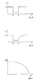
- Fig. 3 shows a time course of the mains voltage U over the time t when a network fault occurs. At time t 1 , a voltage dip occurs, which lasts until time t 2 . Subsequently, the nominal voltage U N is again present in the network.
- Fig. 4 shows a course of the fed by the wind turbine active power P over the time t, which falls as a result of the burglary mains voltage U in t 1 and increases with the incipient mains voltage U from t 2 back to the rated power P N.
- Fig. 5 illustrates the underlying technical problem of the invention.
- Fig. 5 shows a rotor blade curve at rated wind, in which the moment of the rotor blade M R is plotted against the blade pitch ⁇ .
- the change in the torque ⁇ M R only weakly depends on a change in the blade pitch ⁇ . So is tried when a network fault, the moment of the wind turbine with a conventional To control regulators for the blade pitch, this control is very insensitive.
- Fig. 5 shows a rotor blade curve at rated wind, in which the moment of the rotor blade M R is plotted against
Landscapes
- Engineering & Computer Science (AREA)
- Life Sciences & Earth Sciences (AREA)
- Sustainable Development (AREA)
- Sustainable Energy (AREA)
- Chemical & Material Sciences (AREA)
- Combustion & Propulsion (AREA)
- Mechanical Engineering (AREA)
- General Engineering & Computer Science (AREA)
- Physics & Mathematics (AREA)
- Fluid Mechanics (AREA)
- Wind Motors (AREA)
- Control Of Eletrric Generators (AREA)
Abstract
Description
- Die vorliegende Erfindung betrifft ein Verfahren zum Betreiben einer Windenergieanlage bei Auftreten eines Netzfehlers, wobei die Windenergieanlage einen Rotor mit mindestens einem in seinem Blatteinstellwinkel verstellbaren Rotorblatt, einen mit dem Rotor verbundenen Generator zur Erzeugung einer elektrischen Leistung und mindestens eine Einrichtung zum Erfassen eines Istwerts der Drehzahl des Generators, eines Werts des Blatteinstellwinkels und eines Istwerts einer für ein Generatormoment repräsentativen Größe, insbesondere einer Wirkleistung und/oder eines Wirkstroms aufweist. Ebenso betrifft die Erfindung eine Windenergieanlage zur Durchführung des Verfahrens.
- Bei unerwarteten Netzfehlern kann die Windenergieanlage nicht weiterhin die maximale Leistung in das elektrische Netz einspeisen. Der hieraus resultierende schnelle Leistungseinbruch führt zu einem Drehzahlanstieg, auf den entsprechend durch eine Regelung des Blatteinstellwinkels reagiert wird. Hierbei können Schwingungen in der Drehzahl auftreten.
- Aus
WO 2009/083447 A2 ist ein Verfahren zum Betrieb einer Windenergieanlage bei einer geringen Netzspannung bekannt. Im Netzfehlerfall, wenn geringe Netzspannungen vorliegen, wird, ausgehend von der Schnelllaufzahl vor dem Netzfehler, der Pitchwinkel bei der aktuellen Leistung ermittelt. Eine Regelung für den Blatteinstellwinkel wird angesteuert, um während des Netzfehlers den erzeugten Strom konstant zu halten. - Aus
US 6,921,985 B2 ist ein Verfahren zum Betrieb einer Windenergieanlage bei einem Netzfehler bekannt, bei dem eine unterbrechungsfreie Stromversorgung für die Blatteinstellwinkelregelung vorgesehen ist. Die unterbrechungsfreie Stromversorgung greift hierbei auf den Zwischenkreis zwischen netzseitigem und rotorseitigem Umrichter zurück. Mit dem Umschalten auf die unterbrechungsfreie Stromversorgung wird die Blatteinstellwinkelregelung durch die Steuerung der Windenergieanlage aktiviert, um in Reaktion auf den Umschaltvorgang den Blattwinkel entsprechend verstellen. - Aus
WO 2005/015012 A1 ist ein Verfahren zur Steuerung einer Windenergieanlage bei einem Netzfehler bekannt. Im Fall eines Netzfehlers wird ein Betriebsparameter der Windenergieanlage, beispielsweise die Temperatur, erfasst und die Blattwinkelregelung angesteuert, um die Temperatur innerhalb eines vorbestimmten Intervalls zu halten. - Aus
WO 2008/031434 A2 ist ein Verfahren zur Steuerung einer Windenergieanlage bei einem Netzfehler bekannt, bei dem während des Netzfehlers der Blattwinkel solange erhöht wird, bis sich der Rotor nicht weiter beschleunigt. Die im Normalbetrieb übliche Regelung der Drehzahl wird während des Netzfehlers nicht durchgeführt. Die Erhöhung des Blattwinkels wird ausgelöst, wenn die von der Windenergieanlage abgegebene Wirkleistung 125 % der Nennwirkleistung beträgt. - Aus
DE 10 2008 010 543 A1 ist ein Verfahren zum Betreiben einer Windenergieanlage bei einem Netzfehler bekannt, bei dem bereits vor dem Ansteigen der Rotordrehzahl eine Einstellung des Blatteinstellwinkels eingeleitet wird, wobei die Rotor-oder Generatordrehzahl auf eine, sich aus einer im Netzfehlerfall vorliegenden elektrischen Größe und der aktuellen Windgeschwindigkeit ergebende, Solldrehzahl geregelt wird. - Der Erfindung liegt die Aufgabe zugrunde, ein Verfahren und eine Windenergieanlage zur Verfügung zu stellen, mit denen nach einem Netzfehler eine schnelle Lastreduzierung auf einen neuen stabilen Arbeitspunkt ohne Netztrennung möglich ist.
- Erfindungsgemäß wird die Aufgabe durch ein Verfahren mit den Merkmalen aus Anspruch 1 und eine Windenergieanlage mit den Merkmalen aus Anspruch 10 gelöst.
- Das erfindungsgemäße Verfahren dient zum Betreiben einer Windenergieanlage bei Auftreten eines Netzfehlers. Die Windenergieanlage weist einen Rotor mit mindestens einem in seinem Blatteinstellwinkel verstellbaren Rotorblatt, einen mit dem Rotor verbundenen Generator zur Erzeugung einer elektrischen Leistung sowie mindestens eine Einrichtung zum Erfassen eines Istwerts der Drehzahl des Generators, eines Werts des Blatteinstellwinkels und eines Istwerts einer für ein Generatormoment repräsentativen Größe, insbesondere einer Wirkleistung und/oder eines Wirkstroms auf. Die Einrichtung zur Erfassung der Generatordrehzahl muss nicht notwendigerweise die Drehzahl des Generators, sondern kann auch eine andere Drehzahl im Antriebsstrang messen und diese in eine Drehzahl des Generators umrechnen. Bei dem erfindungsgemäßen Verfahren erfolgt ein Erkennen eines Netzfehlers. Ferner erfolgt ein Erfassen der Wirkleistung und/oder des Wirkstroms und der Drehzahl, wenn ein Netzfehler erkannt wurde. In einem weiteren Schritt wird eine Änderung des Generatormoments aufgrund der erfassten Wirkleistung und/oder des erfassten Wirkstroms und der erfassten Drehzahl bestimmt. Bei einem auftretenden Netzfehler ist insbesondere die Änderung des Generatormoments eine kritische Größe. In einem weiteren Schritt wird eine Korrekturgröße für den Blatteinstellwinkel, abhängig von der Änderung des Generatormoments, ermittelt. Aus der Korrekturgröße für den Blatteinstellwinkel und einem drehzahlabhängigen Sollwert für den Blatteinstellwinkel wird ein korrigierter Sollwert für den Blatteinstellwinkel ermittelt. Der drehzahlabhängige Sollwert für den Blatteinstellwinkel ist der Sollwert, der im regulären Betrieb, abhängig von einem Istwert und einem Sollwert der Drehzahl, bestimmt wird. Das erfindungsgemäße Verfahren besitzt eine Reihe von Vorzügen. Ein Vorteil liegt darin, dass weiterhin mit dem drehzahlabhängigen Sollwert gearbeitet und so auf eine Änderung der Windgeschwindigkeit reagiert werden kann. Es wird lediglich eine Korrekturgröße zu dem drehzahlabhängigen Sollwert ermittelt. Weiterhin reagiert das erfindungsgemäße Verfahren sehr schnell auf den auftretenden Netzfehler, da es bereits bei Erkennen des Netzfehlers ausgelöst wird. Durch das schnelle Einsetzen des erfindungsgemäßen Verfahrens kann die Blatteinstellregelung schon auf Momentenänderungen reagieren, die sich in Folge des Netzfehlers ergeben.
- In einer bevorzugten Ausgestaltung erfolgt das Erkennen des Netzfehlers abhängig von der Änderung einer Netzspannung und/oder einer Netzfrequenz. Hierbei kann vorgesehen sein, dass, wenn ein vorbestimmter Schwellwert der Netzspannung und/oder der Netzfrequenz unter- oder überschritten wird, ein Netzfehler erkannt ist. Beispielsweise wird der Netzfehler erkannt, wenn die Netzspannung um mehr als einen vorbestimmten Wert gegenüber einer Nennspannung absinkt.
- In einer weiteren bevorzugten Ausgestaltung des erfindungsgemäßen Verfahrens erfolgt das Erkennen des Netzfehlers abhängig von einer Fehlermeldung, die in einem Umrichter und/oder dem Generator der Windenergieanlage erzeugt wird. Ursachen für eine solche Fehlermeldung können beispielsweise Temperatur- oder Stromüberschreitungen sein.
- Der erfasste Wert des Blatteinstellwinkels kann ein gemessener Istwert sein. Alternativ oder zusätzlich kann der erfasste Wert des Blatteinstellwinkels ein Sollwert für den Blatteinstellwinkel sein, der beispielsweise in einer Steuerung für den Blatteinstellwinkel vorliegt und aus dieser heraus erfasst wird.
- In einer besonders bevorzugten Ausgestaltung des erfindungsgemäßen Verfahrens erfolgt ein Erfassen eines Istwerts oder Sollwerts für den Blatteinstellwinkel. Hierbei wird bei der Ermittlung der Korrekturgröße für den Blatteinstellwinkel, abhängig von der Änderung des Generatormoments, zusätzlich der Istwert oder Sollwert für den Blatteinstellwinkel berücksichtigt. Dieser Ausgestaltung der Erfindung liegt die Erkenntnis zugrunde, dass, abhängig von dem Istwert oder Sollwert für den Blatteinstellwinkel der Windenergieanlage, das von dem Rotorblatt aufgenommene Moment entsprechend eines nichtlinearen Zusammenhangs mit einer Änderung des Blatteinstellwinkels variiert. Insbesondere bei kleinen Blatteinstellwinkeln bewirkt eine Änderung des Blatteinstellwinkels eine geringere Änderung in dem Moment als bei großen Blatteinstellwinkeln.
- In einer bevorzugten Ausgestaltung wird die Korrekturgröße für den Blatteinstellwinkel derart begrenzt, dass eine maximale Änderungsgeschwindigkeit für den Blatteinstellwinkel nicht überschritten wird. Auf diese Weise kann sichergestellt werden, dass die Regelung für den Blatteinstellwinkel nicht übersteuert wird oder Sollwerte vorgegeben werden, die nur mit deutlicher Verzögerung von der Regelung erreicht werden können.
- In einer weiteren bevorzugten Ausgestaltung wird der drehzahlabhängige Sollwert für den Blatteinstellwinkel, wie beim regulären Betrieb, abhängig von der Drehzahl geregelt. Dies erlaubt es, die drehzahlabhängige Regelung des Blatteinstellwinkels auch im Falle eines Netzfehlers fortzuführen und erleichtert die Regelung bei Beendigung des Netzfehlers.
- In einer bevorzugten Weiterbildung des erfindungsgemäßen Verfahrens wird die Korrekturgröße für den Blatteinstellwinkel nach Erkennen des Netzfehlers durch Schließen eines Schalters aufgeschaltet. Der Schalter kann in Hardware oder Software ausgeführt sein. Hierdurch kann erreicht werden, dass die Korrekturgröße unmittelbar nach Eintreten des Netzfehlers einen Beitrag zum Sollwert des Blatteinstellwinkels liefert.
- Die erfindungsgemäße Aufgabe wird ebenfalls durch eine Windenergieanlage gelöst, die einen Rotor mit mindestens einem in seinem Blatteinstellwinkel verstellbaren Rotorblatt sowie eine Blatteinstellregelung aufweist, die für mindestens ein Rotorblatt einen drehzahlabhängigen Sollwert zur Einstellung des Blatteinstellwinkels ermittelt. Die Windenergieanlage besitzt ferner einen mit dem Rotor verbundenen Generator, der eine elektrische Leistung für ein elektrisches Versorgungsnetz erzeugt. Erfindungsgemäß ist eine Steuerung vorgesehen, die, ansprechend auf einen Netzsfehler, eine Änderung des Generatormoments bestimmt und eine Korrekturgröße für den Blatteinstellwinkel, die von der Änderung des Generatormoments und einem Wert des Blatteinstellwinkels abhängig ist, an die Blatteinstellregelung weiterleitet, wobei die Blatteinstellregelung den Blatteinstellwinkel entsprechend einem korrigierten Sollwert einstellt, der sich aus dem drehzahlabhängigen Sollwert für den Blatteinstellwinkel und der Korrekturgröße für den Blatteinstellwinkel bestimmt. Bei der erfindungsgemäßen Windenergieanlage ist eine Steuerung vorgesehen, die auf einen Netzfehler anspricht und eine Korrekturgröße für den Blatteinstellwinkel erzeugt. Die Korrekturgröße für den Blatteinstellwinkel wird zu einem drehzahlabhängigen Sollwert für den Blatteinstellwinkel hinzugefügt, um einen korrigierten Sollwert für den Blatteinstellwinkel zu erhalten, der über eine Blatteinstellregelung eingestellt werden kann. Indem der Korrekturwert für den Blatteinstellwinkel unmittelbar ansprechend auf den Netzfehler erzeugt wird, kann die erfindungsgemäße Windenergieanlage schnell und zuverlässig auf den Netzfehler reagieren.
- In einer bevorzugten Ausgestaltung wird der Korrekturwert für den Blatteinstellwinkel derart begrenzt, dass eine maximale Änderungsgeschwindigkeit für den Blatteinstellwinkel nicht überschritten wird.
- Die vorliegende Erfindung wird anhand eines Ausführungsbeispiels näher erläutert. Es zeigt:
- Fig. 1
- ein Blockdiagramm einer Reglerstruktur zur Bestimmung eines korrigierten Sollwerts für den Blatteinstellwinkel,
- Fig. 2
- ein Blockdiagramm einer alternativen Reglerstruktur zur Bestimmung eines korrigierten Sollwerts für den Blatteinstellwinkel,
- Fig. 3
- einen Verlauf der Spannung über der Zeit bei einem Netzfehler,
- Fig. 4
- einen Verlauf der Wirkleistung über der Zeit bei einem Netzfehler und
- Fig. 5
- den Zusammenhang zwischen Moment und Blatteinstellwinkel.
-
Fig. 1 zeigt in einer schematischen Ansicht eine Reglerstruktur zur Bestimmung eines korrigierten Sollwerts für einen Blatteinstellwinkel βs, corr 34. Als Eingangsgröße liegen an der Reglerstruktur der Sollwert für die Drehzahl ns 20 und der Istwert der Drehzahl na 22 an. Ferner werden der Istwert der Wirkleistung Pa 24 oder des Wirkstroms Ia 25 und der Istwert oder der Sollwert des Blatteinstellwinkels βa, βs 26, 27 verarbeitet. - Der Sollwert für die Drehzahl ns 20 und der Istwert für die Drehzahl na 22 liegen an einem Regler 10 an. Der Regler 10 kann verschiedene Ausgestaltungen besitzen, wobei in jeder Ausgestaltung ein Proportionalglied P vorgesehen ist. Weiterhin kann je nach gewählter Ausgestaltung für den Regler 10 zusätzlich ein Integralglied I oder ein Differenzialglied D oder beides vorgesehen sein. Als Ergebnis liefert der Regler 10 einen Vorschlagswert für den Blatteinstellwinkel βn 30. Wenn der Schalter S1 16 geöffnet ist, wird der Vorschlagswert für den Blatteinstellwinkel βn 30 ohne Hinzufügen eines weiteren Blatteinstellwinkels im Additionsglied 18 als Sollwert für den Blatteinstellwinkel βs, corr 34 an nachfolgende (nicht dargestellte) Verstellantriebe für den Blatteinstellwinkel weitergeleitet.
- Zusätzlich sieht die in
Fig. 1 dargestellte Reglerstruktur vor, dass in Schritt 12 aus dem Istwert der Wirkleistung Pa 24 und dem Istwert der Drehzahl na 22 ein Generatormoment MG berechnet wird. Alternativ kann das Generatormoment MG auch aus einem Istwert eines Stroms Ia, beispielsweise einem Wirkstrom, berechnet werden. Die Berechnung des Generatormoments MG erfolgt hierbei über den Zusammenhang:
- Das so bestimmte Generatormoment MG wird fortlaufend berechnet und die zeitliche Änderung des Generatormoments ΔM 28, abhängig vom Istwert oder Sollwert für den Blatteinstellwinkel βa, βs 26, 27, in einen zusätzlichen Sollwert für den Blatteinstellwinkel bei einem Netzfehler βFRT 32 umgerechnet. In dem Verfahrensschritt 14 findet, abhängig von der Änderung des Generatormoments ΔM 28, eine Verstärkung des Istwertes oder Sollwerts für den Blatteinstellwinkel βa, βs 26, 27 statt, um den zusätzlichen Sollwert für den Blatteinstellwinkel bei einem Netzfehler βFRT 32 zu bestimmen. Insbesondere kann der Netzfehler durch das Auftreten eines Wertes von ΔM erkannt werden, der von null verschieden ist. Alternativ ist es auch möglich, einen Netzfehler durch eine Messung der Netzspannung zu erkennen. Im Fall eines Netzfehlers wird der Schalter S1 16 geschlossen, so dass sich der korrigierte Sollwert für den Blatteinstellwinkel βs, corr 34 als die Summe des Vorschlagswertes für den Blatteinstellwinkel βn 30 und des zusätzlichen Sollwerts für den Blatteinstellwinkel bei einem Netzfehler βFRT 32 ergibt.
-
Fig. 2 zeigt eine alternative Reglerstruktur, bei der weder ein Vorschlagswert für den Blatteinstellwinkel βn 30, noch ein zusätzlicher Sollwert für den Blatteinstellwinkel βFRT 32 ermittelt, sondern die zeitlichen Ableitungen dieser Größen in der Reglerstruktur verarbeitet werden. Der Vorteil, die zeitlichen Ableitungen dieser Größen in der Reglerstruktur zu verarbeiten, liegt darin, dass sich hierbei besonders leicht Geschwindigkeitsbegrenzungen definieren lassen, so dass Sollwerte für den Blatteinstellwinkel eine maximale Verstellgeschwindigkeit für den Blatteinstellwinkel am Rotorblatt berücksichtigen. Bei der alternativen Reglerstruktur gemäßFig. 2 liegen ein Sollwert für die Drehzahl ns 20 und ein Istwert für die Drehzahl na 22 an einem Regler 40 an. Der Regler 40 kann wieder als ein Regler mit einem Proportionalglied P ausgeführt sein, wobei zusätzlich ein Integralglied I und/oder ein Differenzialglied D vorgesehen sein kann. Anders als in dem Ausführungsbeispiel ausFig. 1 wird die Ausgangsgröße des Reglers 40 als zeitliche Ableitung eines Vorschlagwerts für den Blatteinstellwinkel dβn/dt 56 angesehen und weiterverarbeitet. - Wie bereits bei der Reglerstruktur aus
Fig. 1 , wird die zeitliche Ableitung des Vorschlagswerts für den Blatteinstellwinkel dβn/dt 56 in dem Fall, dass kein Netzfehler vorliegt und der Schalter 48 somit geöffnet ist, über das Additionsglied 50 an ein Begrenzungsglied 52 weitergeleitet. Das Begrenzungsglied 52 begrenzt die zeitliche Ableitung des Vorschlagswerts für den Blatteinstellwinkel dβn/dt 56 auf einen zulässigen Maximalwert der Verstellgeschwindigkeit, der von den Verstellantrieben für den Blatteinstellwinkel erreicht werden kann. Die so begrenzte zeitliche Ableitung wird in einem nachfolgenden Schritt 54 über die Zeit integriert, so dass ein korrigierter Sollwert für den Blatteinstellwinkel βs, corr 55 die Ausgangsgröße der Reglerstruktur gemäßFig. 2 bildet. - In einem Verfahrensschritt 42 wird, wie vorstehend erläutert, aus dem anliegenden Istwert für die Drehzahl na 22 und dem Istwert für die Wirkleistung Pa 24 das Generatormoment MG der Windenergieanlage berechnet und dessen zeitliche Änderung ΔM 28 bestimmt. Alternativ kann das Generatormoment MG auch aus dem Istwert eines Stroms Ia, beispielsweise einem Wirkstrom, berechnet werden. Abhängig von der zeitlichen Änderung des Generatormoments ΔM 28 wird der Istwert oder Sollwert für den Blatteinstellwinkel βa, βs 26, 27 in Verfahrensschritt 44 verstärkt, um den zusätzlichen Sollwert für den Blatteinstellwinkel bei Vorliegen eines Netzfehlers βFRT 32 zu erhalten. Im Wesentlichen entspricht der Verfahrensschritt 44 aus
Fig. 2 dem Verfahrensschritt 14 ausFig. 1 . In einem nachfolgenden Verfahrensschritt 46 wird der zusätzliche Sollwert für den Blatteinstellwinkel bei Vorliegen eines Netzfehlers βFRT 32 differenziert, so dass die zeitliche Ableitung des zusätzlichen Sollwerts für den Blatteinstellwinkel bei Vorliegen eines Netzfehlers dβFRT/dt 58 an dem Schalter 48 anliegt. Wird in Verfahrensschritt 42 durch die Änderung des Generatormoments ΔM 28 ein Netzfehler erkannt oder erfolgt aus anderen Gründen die Erkennung eines Netzfehlers, so werden der Schalter S2 48 geschlossen und die zeitlichen Ableitungen des Vorschlagswerts für den Blatteinstellwinkel dβn/dt 56 und des zusätzlichen Sollwerts für den Blatteinstellwinkel bei Vorliegen eines Netzfehlers dβFRT/dt 58 in Schritt 50 addiert. In einem nachfolgenden Schritt 52 erfolgt die Begrenzung der aus den zeitlichen Ableitungen gebildeten Summe auf die maximale Verstellgeschwindigkeit der Verstellantriebe für den Blatteinstellwinkel. Um für die Steuerung der Verstellantriebe einen Sollwert zur Verfügung zu stellen, wird mit dem nachfolgenden Integrator 54 der in Schritt 52 begrenzte Wert integriert und der korrigierte Sollwert für den Blatteinstellwinkel βs, corr 55 ausgegeben. Durch die zeitliche Ableitung des Blatteinstellwinkels, der aus einem steilen Leistungs- bzw. Momentenabfall errechnet wurde, kann die zeitliche Ableitung in Form eines kurzen Impulses vorliegen, der nur eine kurzfristige Verstellung des Blatteinstellwinkels bewirkt. Durch Schritt 52 und die Steuerung der Verstellantriebe für den Blatteinstellwinkel wird sichergestellt, dass der sich ergebende Sollwinkel auch verfahren wird. - Der besondere Vorteil der Reglerstrukturen aus
Fig. 1 und Fig. 2 besteht darin, dass im Fehlerfall durch das Schließen des Schalters S1 16 oder S2 48 die entsprechenden Korrekturwerte 32, 58 aufgeschaltet werden kann, während die sonstige Bestimmung des Sollwerts weiterläuft. Dauert der Fehlerfall bis zu beispielsweise 3 Sekunden, so bleiben die Schalter S1 16 oder S2 48 auch über den Fehlerfall hinaus für eine vorbestimmte Zeit geschlossen. -
Fig. 3 zeigt einen zeitlichen Verlauf der Netzspannung U über der Zeit t bei Auftreten eines Netzfehlers. Zum Zeitpunkt t1 tritt ein Spannungseinbruch auf, der bis zum Zeitpunkt t2 dauert. Anschließend liegt wieder die Nennspannung UN im Netz vor. -
Fig. 4 zeigt einen Verlauf der von der Windenergieanlage eingespeisten Wirkleistung P über der Zeit t, die in Folge der einbrechenden Netzspannung U in t1 fällt und mit der einsetzenden Netzspannung U ab t2 wieder auf die Nennleistung PN steigt. -
Fig. 5 verdeutlicht die der Erfindung zugrundeliegende technische Problematik.Fig. 5 zeigt eine Rotorblattkurve bei Nennwind, bei der das Moment des Rotorblatts MR über dem Blatteinstellwinkel β aufgetragen ist. Im Bereich von kleinen β-Werten ist deutlich zu erkennen, dass die Änderung des Moments ΔMR nur schwach von einer Änderung des Blatteinstellwinkels Δβ abhängt. Wird also bei Auftreten eines Netzfehlers versucht, das Moment der Windenergieanlage mit einem herkömmlichen Regler für den Blatteinstellwinkel zu regeln, so ist diese Regelung sehr unempfindlich. Bei dem erfindungsgemäßen Verfahren wird entsprechendFig. 2 bei der Umrechnung des Moments M in einen Korrekturwert βsFRT 36 durch eine von βa 26 abhängige Verstärkung 32 erreicht, dass der Korrekturwert für kleinere Werte von β größer als für größere β-Werte ausfällt, da das Moment des Rotorblatts MR im Bereich kleinerer Werte von β unempfindlicher für eine Änderung von β ist.
Claims (14)
- Verfahren zum Betreiben einer Windenergieanlage bei Auftreten eines Netzfehlers, wobei die Windenergieanlage einen Rotor mit mindestens einem in seinem Blatteinstellwinkel (β) verstellbaren Rotorblatt, einen mit dem Rotor verbundenen Generator zur Erzeugung einer elektrischen Leistung P und mindestens eine Einrichtung zum Erfassen eines Istwerts der Drehzahl des Generators (na), eines Werts des Blatteinstellwinkels (βa, βs) und eines Istwerts einer für ein Generatormoment (MG) repräsentativen Größe
aufweist, mit folgenden Verfahrensschritten:● Erkennen eines Netzfehlers,● Erfassen des Istwerts der für das Generatormoment (MG) repräsentativen Größe und des Istwerts der Drehzahl des Generators (na), wenn ein Netzfehler erkannt wurde,● Bestimmen einer Änderung des Generatormoments (ΔMG),● Erfassen des Werts für den Blatteinstellwinkel (βa, βs)● Ermitteln einer Korrekturgröße für den Blatteinstellwinkel (β) abhängig von der Änderung des Generatormoments (ΔMG) und dem Wert für den Blatteinstellwinkel (βa, βs),● Bestimmen eines korrigierten Sollwerts für den Blatteinstellwinkel, der sich aus einem drehzahlabhängigen Sollwert für den Blatteinstellwinkel in einem regulären Betrieb und der ermittelten Korrekturgröße für den Blatteinstellwinkel ergibt. - Verfahren nach Anspruch 1, dadurch gekennzeichnet, dass der Istwert einer für das Generatormoment (MG) repräsentativen Größe ein Istwert einer erzeugten Wirkleistung Pa oder eines Wirkstroms Ia ist.
- Verfahren nach Anspruch 1 oder 2, dadurch gekennzeichnet, dass das Erkennen des Netzfehlers abhängig von einer Änderung einer Netzspannung (ΔU) und/oder einer Netzfrequenz (Δf) und/oder einer Fehlermeldung eines Umrichters und/oder des Generators erfolgt.
- Verfahren nach einem der Ansprüche 1 bis 3, dadurch gekennzeichnet, dass das Erkennen des Netzfehlers abhängig von einer Fehlermeldung erfolgt, die in einem Umrichter und/oder dem Generator erzeugt wird.
- Verfahren nach einem der Ansprüche 1 bis 4, dadurch gekennzeichnet, dass ein Istwert des Blatteinstellwinkels erfasst wird.
- Verfahren nach einem der Ansprüche 1 bis 5, dadurch gekennzeichnet, dass ein Sollwert des Blatteinstellwinkels erfasst wird.
- Verfahren nach Anspruch 1 bis 6, gekennzeichnet durch● Erfassen des Istwerts oder Sollwerts für den Blatteinstellwinkel (βa, βs) und● Ermitteln der Korrekturgröße für den Blatteinstellwinkel abhängig von der Änderung des Generatormoments (ΔMG) und dem Istwert oder Sollwert für den Blatteinstellwinkel (βa, βs).
- Verfahren nach einem der Ansprüche 1 bis 7, dadurch gekennzeichnet, dass die Korrekturgröße für den Blatteinstellwinkel als Winkel (βFRT) bestimmt wird.
- Verfahren nach einem der Ansprüche 1 bis 8, dadurch gekennzeichnet, dass die Korrekturgröße für den Blatteinstellwinkel als Änderungsgeschwindigkeit eines Winkels (dβFRT/dt) bestimmt wird.
- Verfahren nach einem der Ansprüche 1 bis 9, dadurch gekennzeichnet, dass die Korrekturgröße für den Blatteinstellwinkel derart begrenzt ist, dass eine maximale Änderungsgeschwindigkeit für den Blatteinstellwinkel nicht überschritten wird.
- Verfahren nach einem der Ansprüche 1 bis 10, dadurch gekennzeichnet, dass der drehzahlabhängige Sollwert für den Blatteinstellwinkel in einem regulären Betrieb abhängig von einem Istwert und einem Sollwert der Drehzahl geregelt wird.
- Verfahren nach einem der Ansprüche 1 bis 11, dadurch gekennzeichnet, dass die Korrekturgröße für den Blatteinstellwinkel nach Erkennen eines Netzfehlers aufgeschaltet wird.
- Windenergieanlage mit einem Rotor, der mindestens ein in seinem Blatteinstellwinkel verstellbares Rotorblatt aufweist, einer Blatteinstellregelung, die für das mindestens eine Rotorblatt einen drehzahlabhängigen Sollwert zur Einstellung des Blatteinstellwinkels ermittelt, und mit einem mit dem Rotor verbundenen Generator, der eine elektrische Leistung für ein elektrisches Versorgungsnetz erzeugt,
dadurch gekennzeichnet, dass
eine Steuerung vorgesehen ist, die ansprechend auf einen Netzfehler eine Änderung eines Generatormoments bestimmt und eine Korrekturgröße für den Blatteinstellwinkel abhängig von der Änderung des Generatormoments und einem Wert für den Blatteinstellwinkel an die Blatteinstellregelung weiterleitet, wobei die Blatteinstellregelung den Blatteinstellwinkel entsprechend einem korrigierten Sollwert einstellt, der sich aus dem drehzahlabhängigen Sollwert für den Blatteinstellwinkel für einen regulären Betrieb und der Korrekturgröße für den Blatteinstellwinkel ergibt. - Windenergieanlage nach Anspruch 13, dadurch gekennzeichnet, dass die Korrekturgröße für den Blatteinstellwinkel derart begrenzt ist, dass eine maximale Änderungsgeschwindigkeit für den Blatteinstellwinkel nicht überschritten wird.
Applications Claiming Priority (1)
| Application Number | Priority Date | Filing Date | Title |
|---|---|---|---|
| DE102011105854A DE102011105854B4 (de) | 2011-06-03 | 2011-06-03 | Verfahren zum Betreiben einer Windenergieanlage bei Auftreten eines Netzfehlers sowie eine solche Windenergieanlage |
Publications (4)
| Publication Number | Publication Date |
|---|---|
| EP2530303A2 true EP2530303A2 (de) | 2012-12-05 |
| EP2530303A3 EP2530303A3 (de) | 2013-07-10 |
| EP2530303B1 EP2530303B1 (de) | 2017-07-26 |
| EP2530303B2 EP2530303B2 (de) | 2020-08-26 |
Family
ID=45977087
Family Applications (1)
| Application Number | Title | Priority Date | Filing Date |
|---|---|---|---|
| EP12002187.8A Active EP2530303B2 (de) | 2011-06-03 | 2012-03-27 | Verfahren zum Betreiben einer Windenergieanlage bei Auftreten eines Netzfehlers sowie eine solche Windenergieanlage |
Country Status (6)
| Country | Link |
|---|---|
| US (1) | US8618685B2 (de) |
| EP (1) | EP2530303B2 (de) |
| CN (1) | CN102808729A (de) |
| DE (1) | DE102011105854B4 (de) |
| DK (1) | DK2530303T4 (de) |
| ES (1) | ES2645021T5 (de) |
Cited By (2)
| Publication number | Priority date | Publication date | Assignee | Title |
|---|---|---|---|---|
| CN103590973A (zh) * | 2013-11-23 | 2014-02-19 | 大连尚能科技发展有限公司 | 一种应用于风力发电机组大风工况下的变桨控制方法 |
| EP3719301A1 (de) | 2019-04-03 | 2020-10-07 | Nordex Energy GmbH | Verfahren zum betrieb einer windenergieanlage mit mindestens einem in seinem blatteinstellwinkel verstellbaren rotorblatt |
Families Citing this family (9)
| Publication number | Priority date | Publication date | Assignee | Title |
|---|---|---|---|---|
| EP2365215B1 (de) * | 2010-03-10 | 2012-12-12 | Siemens Aktiengesellschaft | Drehzahlsteuerung einer Windturbine basierend auf der Rotorbeschleunigung |
| US20140286776A1 (en) * | 2011-10-28 | 2014-09-25 | General Electric Company | Blade Pitch System for a Wind Turbine Generator and Method of Operating the Same |
| DE102013207264A1 (de) * | 2013-04-22 | 2014-10-23 | Wobben Properties Gmbh | Verfahren zum Steuern eines Windparks |
| ES2527972B1 (es) * | 2013-08-02 | 2015-11-20 | Gamesa Innovation & Technology, S.L. | Gestión inteligente de la potencia durante una caída de tensión en los aerogeneradores |
| EP3074629B1 (de) * | 2013-11-29 | 2022-06-22 | Vestas Wind Systems A/S | Stromsteigungs-vorwärtskopplung |
| US10669990B2 (en) * | 2015-06-11 | 2020-06-02 | Vestas Wind Systems A/S | Ramping power in a wind turbine using gain scheduling |
| DK3444938T3 (da) * | 2017-08-18 | 2021-02-22 | Nordex Energy Se & Co Kg | Fremgangsmåde til styring af en vindturbine |
| EP3502811A1 (de) * | 2017-12-21 | 2019-06-26 | Siemens Aktiengesellschaft | Antriebssteuerung mit eigenständiger fehlerkorrektur von lagefehlern |
| CN111365199B (zh) * | 2020-03-11 | 2021-01-26 | 天津发现技术有限公司 | 一种风电机组辅助分析系统 |
Citations (5)
| Publication number | Priority date | Publication date | Assignee | Title |
|---|---|---|---|---|
| WO2005015012A1 (en) | 2003-08-07 | 2005-02-17 | Vestas Wind Systems A/S | Method of controlling a wind turbine connected to an electric utility grid during malfunction in said electric utility grid, control system, wind turbine and family hereof |
| US6921985B2 (en) | 2003-01-24 | 2005-07-26 | General Electric Company | Low voltage ride through for wind turbine generators |
| WO2008031434A2 (en) | 2006-09-14 | 2008-03-20 | Vestas Wind Systems A/S | Method for controlling a wind turbine connected to the utility grid, wind turbine and wind park |
| WO2009083447A2 (en) | 2007-12-28 | 2009-07-09 | Vestas Wind Systems A/S | Apparatus and method for operating a wind turbine under low utility grid voltage conditions |
| DE102008010543A1 (de) | 2008-02-22 | 2009-08-27 | Nordex Energy Gmbh | Verfahren zum Betreiben einer Windenergieanlage und Windenergieanlage |
Family Cites Families (28)
| Publication number | Priority date | Publication date | Assignee | Title |
|---|---|---|---|---|
| US4656362A (en) * | 1982-11-08 | 1987-04-07 | United Technologies Corporation | Blade pitch angle control for large wind turbines |
| US4426192A (en) * | 1983-02-07 | 1984-01-17 | U.S. Windpower, Inc. | Method and apparatus for controlling windmill blade pitch |
| US4695736A (en) | 1985-11-18 | 1987-09-22 | United Technologies Corporation | Variable speed wind turbine |
| US5083039B1 (en) * | 1991-02-01 | 1999-11-16 | Zond Energy Systems Inc | Variable speed wind turbine |
| US6420795B1 (en) * | 1998-08-08 | 2002-07-16 | Zond Energy Systems, Inc. | Variable speed wind turbine generator |
| US6600240B2 (en) * | 1997-08-08 | 2003-07-29 | General Electric Company | Variable speed wind turbine generator |
| US6137187A (en) * | 1997-08-08 | 2000-10-24 | Zond Energy Systems, Inc. | Variable speed wind turbine generator |
| DE19756777B4 (de) | 1997-12-19 | 2005-07-21 | Wobben, Aloys, Dipl.-Ing. | Verfahren zum Betreiben einer Windenergieanlage sowie Windenergieanlage |
| AU2001274396A1 (en) * | 2000-05-23 | 2001-12-03 | Vestas Wind Systems A/S | Variable speed wind turbine having a matrix converter |
| US7015595B2 (en) * | 2002-02-11 | 2006-03-21 | Vestas Wind Systems A/S | Variable speed wind turbine having a passive grid side rectifier with scalar power control and dependent pitch control |
| US7042110B2 (en) * | 2003-05-07 | 2006-05-09 | Clipper Windpower Technology, Inc. | Variable speed distributed drive train wind turbine system |
| US7289920B2 (en) | 2003-06-26 | 2007-10-30 | General Electric Company | Method and apparatus for capture of grid characteristics corresponding to fluctuation events |
| EP1665494B2 (de) * | 2003-09-03 | 2023-06-28 | Siemens Gamesa Renewable Energy Service GmbH | Verfahren zum betrieb bzw. regelung einer windenergieanlage sowie verfahren zur bereitstellung von primärregelleistung mit windenergieanlagen |
| DE102005029000B4 (de) | 2005-06-21 | 2007-04-12 | Repower Systems Ag | Verfahren und System zur Regelung der Drehzahl eines Rotors einer Windenergieanlage |
| GB0523087D0 (en) | 2005-11-11 | 2005-12-21 | Alstom Power Conversion Ltd | Power converters |
| US7425771B2 (en) * | 2006-03-17 | 2008-09-16 | Ingeteam S.A. | Variable speed wind turbine having an exciter machine and a power converter not connected to the grid |
| CN101401294B (zh) * | 2006-03-17 | 2013-04-17 | 英捷电力技术有限公司 | 具有激励器设备和不连接至电网的功率变换器的变速风机 |
| US7586216B2 (en) | 2006-06-02 | 2009-09-08 | General Electric Company | Redundant electrical brake and protection system for electric generators |
| JP4365394B2 (ja) * | 2006-09-20 | 2009-11-18 | 株式会社日立製作所 | 風力発電システムおよびその運転方法 |
| JP4501958B2 (ja) | 2007-05-09 | 2010-07-14 | 株式会社日立製作所 | 風力発電システムおよびその制御方法 |
| JP2008301584A (ja) * | 2007-05-30 | 2008-12-11 | Hitachi Ltd | 風力発電システムおよび電力変換器の制御方法 |
| DE102007060958A1 (de) * | 2007-12-14 | 2009-06-25 | Repower Systems Ag | Steuereinrichtung für Windenergieanlagen mit Netzausfallerkennung |
| CN101919134B (zh) | 2007-12-19 | 2013-04-24 | 维斯塔斯风力系统集团公司 | 用于风力涡轮发电机的基于事件的控制系统及控制方法 |
| US8198742B2 (en) | 2007-12-28 | 2012-06-12 | Vestas Wind Systems A/S | Variable speed wind turbine with a doubly-fed induction generator and rotor and grid inverters that use scalar controls |
| ATE552421T1 (de) | 2008-05-14 | 2012-04-15 | Alstom Wind Sl | Verfahren zur reduktion von torsionsschwingungen im antriebsstrang einer windturbine |
| US8030791B2 (en) * | 2008-07-31 | 2011-10-04 | Rockwell Automation Technologies, Inc. | Current source converter-based wind energy system |
| US8188610B2 (en) | 2008-09-08 | 2012-05-29 | General Electric Company | Wind turbine having a main power converter and an auxiliary power converter and a method for the control thereof |
| DE102009027981B4 (de) | 2009-07-23 | 2011-04-28 | Suzlon Energy Gmbh | Verfahren zum Betreiben einer an einem Stromnetz angeschlossenen Windturbine sowie zur Durchführung des Verfahrens geeignete Windturbine |
-
2011
- 2011-06-03 DE DE102011105854A patent/DE102011105854B4/de not_active Expired - Fee Related
-
2012
- 2012-03-27 DK DK12002187.8T patent/DK2530303T4/da active
- 2012-03-27 EP EP12002187.8A patent/EP2530303B2/de active Active
- 2012-03-27 ES ES12002187T patent/ES2645021T5/es active Active
- 2012-06-01 CN CN2012101783531A patent/CN102808729A/zh active Pending
- 2012-06-03 US US13/487,235 patent/US8618685B2/en active Active
Patent Citations (5)
| Publication number | Priority date | Publication date | Assignee | Title |
|---|---|---|---|---|
| US6921985B2 (en) | 2003-01-24 | 2005-07-26 | General Electric Company | Low voltage ride through for wind turbine generators |
| WO2005015012A1 (en) | 2003-08-07 | 2005-02-17 | Vestas Wind Systems A/S | Method of controlling a wind turbine connected to an electric utility grid during malfunction in said electric utility grid, control system, wind turbine and family hereof |
| WO2008031434A2 (en) | 2006-09-14 | 2008-03-20 | Vestas Wind Systems A/S | Method for controlling a wind turbine connected to the utility grid, wind turbine and wind park |
| WO2009083447A2 (en) | 2007-12-28 | 2009-07-09 | Vestas Wind Systems A/S | Apparatus and method for operating a wind turbine under low utility grid voltage conditions |
| DE102008010543A1 (de) | 2008-02-22 | 2009-08-27 | Nordex Energy Gmbh | Verfahren zum Betreiben einer Windenergieanlage und Windenergieanlage |
Cited By (4)
| Publication number | Priority date | Publication date | Assignee | Title |
|---|---|---|---|---|
| CN103590973A (zh) * | 2013-11-23 | 2014-02-19 | 大连尚能科技发展有限公司 | 一种应用于风力发电机组大风工况下的变桨控制方法 |
| CN103590973B (zh) * | 2013-11-23 | 2015-12-30 | 大连尚能科技发展有限公司 | 一种应用于风力发电机组大风工况下的变桨控制方法 |
| EP3719301A1 (de) | 2019-04-03 | 2020-10-07 | Nordex Energy GmbH | Verfahren zum betrieb einer windenergieanlage mit mindestens einem in seinem blatteinstellwinkel verstellbaren rotorblatt |
| US11268492B2 (en) | 2019-04-03 | 2022-03-08 | Nordex Energy Gmbh | Method for operating a wind turbine to control rotational speed of a wind turbine in the event of a grid error |
Also Published As
| Publication number | Publication date |
|---|---|
| EP2530303B2 (de) | 2020-08-26 |
| ES2645021T5 (es) | 2021-06-09 |
| DE102011105854B4 (de) | 2013-04-11 |
| US8618685B2 (en) | 2013-12-31 |
| DK2530303T3 (da) | 2017-11-06 |
| EP2530303A3 (de) | 2013-07-10 |
| DE102011105854A1 (de) | 2012-12-06 |
| EP2530303B1 (de) | 2017-07-26 |
| US20120306203A1 (en) | 2012-12-06 |
| CN102808729A (zh) | 2012-12-05 |
| ES2645021T3 (es) | 2017-12-01 |
| DK2530303T4 (da) | 2020-11-02 |
Similar Documents
| Publication | Publication Date | Title |
|---|---|---|
| DE102011105854B4 (de) | Verfahren zum Betreiben einer Windenergieanlage bei Auftreten eines Netzfehlers sowie eine solche Windenergieanlage | |
| EP2875562B1 (de) | Verfahren zum steuern eines windparks | |
| EP2872777B1 (de) | Verfahren zum steuern eines elektrischen erzeugers | |
| EP3095165B1 (de) | Verfahren und regel- und/oder steuereinrichtung zum betrieb einer windenergieanlage und/oder eines windparks sowie windenergieanlage und windpark | |
| EP2556247B1 (de) | Dynamische trägheitsregelung | |
| EP1970562B1 (de) | Verfahren zum Betreiben einer Windenergieanlage bei plötzlichen Spannungsänderungen im Netz | |
| EP2525083B1 (de) | Verfahren zum Betreiben einer Windenergieanlage | |
| EP2457320B1 (de) | Verfahren zum betreiben einer windturbine sowie dazu geeignete windturbine | |
| EP3095168B1 (de) | Verfahren und regel- und/oder steuereinrichtung zum betrieb einer windenergieanlage und/oder eines windparks sowie windenergieanlage und windpark | |
| EP2217805A2 (de) | Steuereinrichtung für windenergieanlagen mit netzaufallerkennung | |
| EP2463520A2 (de) | Verfahren zum Betrieb einer pitchgeregelten Windenergieanlage | |
| EP2764239B1 (de) | Verfahren zum betreiben einer windenergieanlage und entsprechende windenergieanlage | |
| EP3444938B1 (de) | Verfahren zur steuerung einer windenergieanlage | |
| EP2238665B1 (de) | Verfahren zum betreiben einer windenergieanlage | |
| EP2562414B1 (de) | Verfahren zum Betreiben einer Windenergieanlage bei Auftreten eines Netzfehlers mit einem Spannungsrückgang sowie eine solche Windenergieanlage | |
| EP2454033B1 (de) | Bandzug- und Schlingenregelung | |
| EP2423464A1 (de) | Verfahren zum Regeln eines Turbosatzes | |
| WO2019122311A1 (de) | Überwachungsverfahren für eine windkraftanlage, zugehörige überwachungsvorrichtung sowie windkraftanlage mit überwachungsvorrichtung | |
| WO2004005675A2 (de) | Verfahren und vorrichtung zur drehzahlregelung einer mittels eines generators an ein elektrisches energieversorgungsnetz angeschalteten turbine | |
| DE102011119942A1 (de) | Verfahren zum Betreiben einer Windenergieanlage und zur Ausübung des Verfahrens befähigte Windenergieanlage | |
| EP3444939B1 (de) | Verfahren zur steuerung einer windenergieanlage | |
| EP2626998B1 (de) | Stromregelung für eine elektrische Maschine und zugehöriges Regelverfahren | |
| EP3768970A1 (de) | Verfahren zum betreiben einer windenergieanlage, windenergieanlage und windpark | |
| EP3176430A1 (de) | Verfahren zum überwachen einer windenergieanlage |
Legal Events
| Date | Code | Title | Description |
|---|---|---|---|
| PUAI | Public reference made under article 153(3) epc to a published international application that has entered the european phase |
Free format text: ORIGINAL CODE: 0009012 |
|
| AK | Designated contracting states |
Kind code of ref document: A2 Designated state(s): AL AT BE BG CH CY CZ DE DK EE ES FI FR GB GR HR HU IE IS IT LI LT LU LV MC MK MT NL NO PL PT RO RS SE SI SK SM TR |
|
| AX | Request for extension of the european patent |
Extension state: BA ME |
|
| PUAL | Search report despatched |
Free format text: ORIGINAL CODE: 0009013 |
|
| AK | Designated contracting states |
Kind code of ref document: A3 Designated state(s): AL AT BE BG CH CY CZ DE DK EE ES FI FR GB GR HR HU IE IS IT LI LT LU LV MC MK MT NL NO PL PT RO RS SE SI SK SM TR |
|
| AX | Request for extension of the european patent |
Extension state: BA ME |
|
| RIC1 | Information provided on ipc code assigned before grant |
Ipc: F03D 7/02 20060101AFI20130604BHEP |
|
| 17P | Request for examination filed |
Effective date: 20140109 |
|
| RBV | Designated contracting states (corrected) |
Designated state(s): AL AT BE BG CH CY CZ DE DK EE ES FI FR GB GR HR HU IE IS IT LI LT LU LV MC MK MT NL NO PL PT RO RS SE SI SK SM TR |
|
| 17Q | First examination report despatched |
Effective date: 20140827 |
|
| STAA | Information on the status of an ep patent application or granted ep patent |
Free format text: STATUS: EXAMINATION IS IN PROGRESS |
|
| GRAP | Despatch of communication of intention to grant a patent |
Free format text: ORIGINAL CODE: EPIDOSNIGR1 |
|
| STAA | Information on the status of an ep patent application or granted ep patent |
Free format text: STATUS: GRANT OF PATENT IS INTENDED |
|
| INTG | Intention to grant announced |
Effective date: 20170216 |
|
| GRAS | Grant fee paid |
Free format text: ORIGINAL CODE: EPIDOSNIGR3 |
|
| GRAA | (expected) grant |
Free format text: ORIGINAL CODE: 0009210 |
|
| STAA | Information on the status of an ep patent application or granted ep patent |
Free format text: STATUS: THE PATENT HAS BEEN GRANTED |
|
| AK | Designated contracting states |
Kind code of ref document: B1 Designated state(s): AL AT BE BG CH CY CZ DE DK EE ES FI FR GB GR HR HU IE IS IT LI LT LU LV MC MK MT NL NO PL PT RO RS SE SI SK SM TR |
|
| REG | Reference to a national code |
Ref country code: GB Ref legal event code: FG4D Free format text: NOT ENGLISH |
|
| REG | Reference to a national code |
Ref country code: CH Ref legal event code: EP |
|
| REG | Reference to a national code |
Ref country code: AT Ref legal event code: REF Ref document number: 912632 Country of ref document: AT Kind code of ref document: T Effective date: 20170815 |
|
| REG | Reference to a national code |
Ref country code: IE Ref legal event code: FG4D Free format text: LANGUAGE OF EP DOCUMENT: GERMAN |
|
| REG | Reference to a national code |
Ref country code: DE Ref legal event code: R096 Ref document number: 502012010837 Country of ref document: DE |
|
| REG | Reference to a national code |
Ref country code: DK Ref legal event code: T3 Effective date: 20171102 |
|
| REG | Reference to a national code |
Ref country code: NL Ref legal event code: MP Effective date: 20170726 |
|
| REG | Reference to a national code |
Ref country code: ES Ref legal event code: FG2A Ref document number: 2645021 Country of ref document: ES Kind code of ref document: T3 Effective date: 20171201 |
|
| REG | Reference to a national code |
Ref country code: LT Ref legal event code: MG4D |
|
| PG25 | Lapsed in a contracting state [announced via postgrant information from national office to epo] |
Ref country code: LT Free format text: LAPSE BECAUSE OF FAILURE TO SUBMIT A TRANSLATION OF THE DESCRIPTION OR TO PAY THE FEE WITHIN THE PRESCRIBED TIME-LIMIT Effective date: 20170726 Ref country code: NL Free format text: LAPSE BECAUSE OF FAILURE TO SUBMIT A TRANSLATION OF THE DESCRIPTION OR TO PAY THE FEE WITHIN THE PRESCRIBED TIME-LIMIT Effective date: 20170726 Ref country code: SE Free format text: LAPSE BECAUSE OF FAILURE TO SUBMIT A TRANSLATION OF THE DESCRIPTION OR TO PAY THE FEE WITHIN THE PRESCRIBED TIME-LIMIT Effective date: 20170726 Ref country code: HR Free format text: LAPSE BECAUSE OF FAILURE TO SUBMIT A TRANSLATION OF THE DESCRIPTION OR TO PAY THE FEE WITHIN THE PRESCRIBED TIME-LIMIT Effective date: 20170726 Ref country code: FI Free format text: LAPSE BECAUSE OF FAILURE TO SUBMIT A TRANSLATION OF THE DESCRIPTION OR TO PAY THE FEE WITHIN THE PRESCRIBED TIME-LIMIT Effective date: 20170726 Ref country code: NO Free format text: LAPSE BECAUSE OF FAILURE TO SUBMIT A TRANSLATION OF THE DESCRIPTION OR TO PAY THE FEE WITHIN THE PRESCRIBED TIME-LIMIT Effective date: 20171026 |
|
| PG25 | Lapsed in a contracting state [announced via postgrant information from national office to epo] |
Ref country code: IS Free format text: LAPSE BECAUSE OF FAILURE TO SUBMIT A TRANSLATION OF THE DESCRIPTION OR TO PAY THE FEE WITHIN THE PRESCRIBED TIME-LIMIT Effective date: 20171126 Ref country code: RS Free format text: LAPSE BECAUSE OF FAILURE TO SUBMIT A TRANSLATION OF THE DESCRIPTION OR TO PAY THE FEE WITHIN THE PRESCRIBED TIME-LIMIT Effective date: 20170726 Ref country code: PL Free format text: LAPSE BECAUSE OF FAILURE TO SUBMIT A TRANSLATION OF THE DESCRIPTION OR TO PAY THE FEE WITHIN THE PRESCRIBED TIME-LIMIT Effective date: 20170726 Ref country code: LV Free format text: LAPSE BECAUSE OF FAILURE TO SUBMIT A TRANSLATION OF THE DESCRIPTION OR TO PAY THE FEE WITHIN THE PRESCRIBED TIME-LIMIT Effective date: 20170726 Ref country code: BG Free format text: LAPSE BECAUSE OF FAILURE TO SUBMIT A TRANSLATION OF THE DESCRIPTION OR TO PAY THE FEE WITHIN THE PRESCRIBED TIME-LIMIT Effective date: 20171026 Ref country code: GR Free format text: LAPSE BECAUSE OF FAILURE TO SUBMIT A TRANSLATION OF THE DESCRIPTION OR TO PAY THE FEE WITHIN THE PRESCRIBED TIME-LIMIT Effective date: 20171027 |
|
| REG | Reference to a national code |
Ref country code: DE Ref legal event code: R026 Ref document number: 502012010837 Country of ref document: DE |
|
| PG25 | Lapsed in a contracting state [announced via postgrant information from national office to epo] |
Ref country code: RO Free format text: LAPSE BECAUSE OF FAILURE TO SUBMIT A TRANSLATION OF THE DESCRIPTION OR TO PAY THE FEE WITHIN THE PRESCRIBED TIME-LIMIT Effective date: 20170726 Ref country code: CZ Free format text: LAPSE BECAUSE OF FAILURE TO SUBMIT A TRANSLATION OF THE DESCRIPTION OR TO PAY THE FEE WITHIN THE PRESCRIBED TIME-LIMIT Effective date: 20170726 |
|
| PLBI | Opposition filed |
Free format text: ORIGINAL CODE: 0009260 |
|
| PLAX | Notice of opposition and request to file observation + time limit sent |
Free format text: ORIGINAL CODE: EPIDOSNOBS2 |
|
| PG25 | Lapsed in a contracting state [announced via postgrant information from national office to epo] |
Ref country code: SM Free format text: LAPSE BECAUSE OF FAILURE TO SUBMIT A TRANSLATION OF THE DESCRIPTION OR TO PAY THE FEE WITHIN THE PRESCRIBED TIME-LIMIT Effective date: 20170726 Ref country code: SK Free format text: LAPSE BECAUSE OF FAILURE TO SUBMIT A TRANSLATION OF THE DESCRIPTION OR TO PAY THE FEE WITHIN THE PRESCRIBED TIME-LIMIT Effective date: 20170726 Ref country code: IT Free format text: LAPSE BECAUSE OF FAILURE TO SUBMIT A TRANSLATION OF THE DESCRIPTION OR TO PAY THE FEE WITHIN THE PRESCRIBED TIME-LIMIT Effective date: 20170726 Ref country code: EE Free format text: LAPSE BECAUSE OF FAILURE TO SUBMIT A TRANSLATION OF THE DESCRIPTION OR TO PAY THE FEE WITHIN THE PRESCRIBED TIME-LIMIT Effective date: 20170726 |
|
| 26 | Opposition filed |
Opponent name: SUZLON ENERGY LTD. Effective date: 20180425 |
|
| PG25 | Lapsed in a contracting state [announced via postgrant information from national office to epo] |
Ref country code: SI Free format text: LAPSE BECAUSE OF FAILURE TO SUBMIT A TRANSLATION OF THE DESCRIPTION OR TO PAY THE FEE WITHIN THE PRESCRIBED TIME-LIMIT Effective date: 20170726 |
|
| PLBB | Reply of patent proprietor to notice(s) of opposition received |
Free format text: ORIGINAL CODE: EPIDOSNOBS3 |
|
| PG25 | Lapsed in a contracting state [announced via postgrant information from national office to epo] |
Ref country code: MT Free format text: LAPSE BECAUSE OF FAILURE TO SUBMIT A TRANSLATION OF THE DESCRIPTION OR TO PAY THE FEE WITHIN THE PRESCRIBED TIME-LIMIT Effective date: 20170726 |
|
| REG | Reference to a national code |
Ref country code: CH Ref legal event code: PL |
|
| PG25 | Lapsed in a contracting state [announced via postgrant information from national office to epo] |
Ref country code: MC Free format text: LAPSE BECAUSE OF FAILURE TO SUBMIT A TRANSLATION OF THE DESCRIPTION OR TO PAY THE FEE WITHIN THE PRESCRIBED TIME-LIMIT Effective date: 20170726 |
|
| REG | Reference to a national code |
Ref country code: BE Ref legal event code: MM Effective date: 20180331 |
|
| REG | Reference to a national code |
Ref country code: IE Ref legal event code: MM4A |
|
| PG25 | Lapsed in a contracting state [announced via postgrant information from national office to epo] |
Ref country code: LU Free format text: LAPSE BECAUSE OF NON-PAYMENT OF DUE FEES Effective date: 20180327 |
|
| PG25 | Lapsed in a contracting state [announced via postgrant information from national office to epo] |
Ref country code: IE Free format text: LAPSE BECAUSE OF NON-PAYMENT OF DUE FEES Effective date: 20180327 |
|
| PG25 | Lapsed in a contracting state [announced via postgrant information from national office to epo] |
Ref country code: LI Free format text: LAPSE BECAUSE OF NON-PAYMENT OF DUE FEES Effective date: 20180331 Ref country code: BE Free format text: LAPSE BECAUSE OF NON-PAYMENT OF DUE FEES Effective date: 20180331 Ref country code: CH Free format text: LAPSE BECAUSE OF NON-PAYMENT OF DUE FEES Effective date: 20180331 |
|
| PG25 | Lapsed in a contracting state [announced via postgrant information from national office to epo] |
Ref country code: FR Free format text: LAPSE BECAUSE OF NON-PAYMENT OF DUE FEES Effective date: 20180331 |
|
| PGFP | Annual fee paid to national office [announced via postgrant information from national office to epo] |
Ref country code: GB Payment date: 20190325 Year of fee payment: 8 |
|
| REG | Reference to a national code |
Ref country code: AT Ref legal event code: MM01 Ref document number: 912632 Country of ref document: AT Kind code of ref document: T Effective date: 20180327 |
|
| PG25 | Lapsed in a contracting state [announced via postgrant information from national office to epo] |
Ref country code: AT Free format text: LAPSE BECAUSE OF NON-PAYMENT OF DUE FEES Effective date: 20180327 |
|
| PG25 | Lapsed in a contracting state [announced via postgrant information from national office to epo] |
Ref country code: TR Free format text: LAPSE BECAUSE OF FAILURE TO SUBMIT A TRANSLATION OF THE DESCRIPTION OR TO PAY THE FEE WITHIN THE PRESCRIBED TIME-LIMIT Effective date: 20170726 |
|
| PG25 | Lapsed in a contracting state [announced via postgrant information from national office to epo] |
Ref country code: PT Free format text: LAPSE BECAUSE OF FAILURE TO SUBMIT A TRANSLATION OF THE DESCRIPTION OR TO PAY THE FEE WITHIN THE PRESCRIBED TIME-LIMIT Effective date: 20170726 Ref country code: HU Free format text: LAPSE BECAUSE OF FAILURE TO SUBMIT A TRANSLATION OF THE DESCRIPTION OR TO PAY THE FEE WITHIN THE PRESCRIBED TIME-LIMIT; INVALID AB INITIO Effective date: 20120327 |
|
| PG25 | Lapsed in a contracting state [announced via postgrant information from national office to epo] |
Ref country code: CY Free format text: LAPSE BECAUSE OF FAILURE TO SUBMIT A TRANSLATION OF THE DESCRIPTION OR TO PAY THE FEE WITHIN THE PRESCRIBED TIME-LIMIT Effective date: 20170726 Ref country code: MK Free format text: LAPSE BECAUSE OF NON-PAYMENT OF DUE FEES Effective date: 20170726 |
|
| PUAH | Patent maintained in amended form |
Free format text: ORIGINAL CODE: 0009272 |
|
| STAA | Information on the status of an ep patent application or granted ep patent |
Free format text: STATUS: PATENT MAINTAINED AS AMENDED |
|
| PG25 | Lapsed in a contracting state [announced via postgrant information from national office to epo] |
Ref country code: AL Free format text: LAPSE BECAUSE OF FAILURE TO SUBMIT A TRANSLATION OF THE DESCRIPTION OR TO PAY THE FEE WITHIN THE PRESCRIBED TIME-LIMIT Effective date: 20170726 |
|
| 27A | Patent maintained in amended form |
Effective date: 20200826 |
|
| AK | Designated contracting states |
Kind code of ref document: B2 Designated state(s): AL AT BE BG CH CY CZ DE DK EE ES FI FR GB GR HR HU IE IS IT LI LT LU LV MC MK MT NL NO PL PT RO RS SE SI SK SM TR |
|
| REG | Reference to a national code |
Ref country code: DE Ref legal event code: R102 Ref document number: 502012010837 Country of ref document: DE |
|
| REG | Reference to a national code |
Ref country code: DK Ref legal event code: T4 Effective date: 20201027 |
|
| REG | Reference to a national code |
Ref country code: DE Ref legal event code: R082 Ref document number: 502012010837 Country of ref document: DE Representative=s name: HAUCK PATENTANWALTSPARTNERSCHAFT MBB, DE Ref country code: DE Ref legal event code: R081 Ref document number: 502012010837 Country of ref document: DE Owner name: NORDEX ENERGY SE & CO. KG, DE Free format text: FORMER OWNER: NORDEX ENERGY GMBH, 22419 HAMBURG, DE |
|
| GBPC | Gb: european patent ceased through non-payment of renewal fee |
Effective date: 20200327 |
|
| PG25 | Lapsed in a contracting state [announced via postgrant information from national office to epo] |
Ref country code: GB Free format text: LAPSE BECAUSE OF NON-PAYMENT OF DUE FEES Effective date: 20200327 |
|
| REG | Reference to a national code |
Ref country code: ES Ref legal event code: DC2A Ref document number: 2645021 Country of ref document: ES Kind code of ref document: T5 Effective date: 20210609 |
|
| PGFP | Annual fee paid to national office [announced via postgrant information from national office to epo] |
Ref country code: DK Payment date: 20230323 Year of fee payment: 12 |
|
| P01 | Opt-out of the competence of the unified patent court (upc) registered |
Effective date: 20230602 |
|
| PGFP | Annual fee paid to national office [announced via postgrant information from national office to epo] |
Ref country code: ES Payment date: 20230414 Year of fee payment: 12 |
|
| PGFP | Annual fee paid to national office [announced via postgrant information from national office to epo] |
Ref country code: DE Payment date: 20240321 Year of fee payment: 13 |