EP2529958A2 - System, method, and program for detecting deflated tires - Google Patents
System, method, and program for detecting deflated tires Download PDFInfo
- Publication number
- EP2529958A2 EP2529958A2 EP12169472A EP12169472A EP2529958A2 EP 2529958 A2 EP2529958 A2 EP 2529958A2 EP 12169472 A EP12169472 A EP 12169472A EP 12169472 A EP12169472 A EP 12169472A EP 2529958 A2 EP2529958 A2 EP 2529958A2
- Authority
- EP
- European Patent Office
- Prior art keywords
- value
- tires
- predetermined
- rotation speed
- vehicle
- Prior art date
- Legal status (The legal status is an assumption and is not a legal conclusion. Google has not performed a legal analysis and makes no representation as to the accuracy of the status listed.)
- Granted
Links
Images


Classifications
-
- B—PERFORMING OPERATIONS; TRANSPORTING
- B60—VEHICLES IN GENERAL
- B60C—VEHICLE TYRES; TYRE INFLATION; TYRE CHANGING; CONNECTING VALVES TO INFLATABLE ELASTIC BODIES IN GENERAL; DEVICES OR ARRANGEMENTS RELATED TO TYRES
- B60C23/00—Devices for measuring, signalling, controlling, or distributing tyre pressure or temperature, specially adapted for mounting on vehicles; Arrangement of tyre inflating devices on vehicles, e.g. of pumps or of tanks; Tyre cooling arrangements
- B60C23/06—Signalling devices actuated by deformation of the tyre, e.g. tyre mounted deformation sensors or indirect determination of tyre deformation based on wheel speed, wheel-centre to ground distance or inclination of wheel axle
- B60C23/061—Signalling devices actuated by deformation of the tyre, e.g. tyre mounted deformation sensors or indirect determination of tyre deformation based on wheel speed, wheel-centre to ground distance or inclination of wheel axle by monitoring wheel speed
Definitions
- the present invention relates to a system, a method, and a program for detecting deflated tires. More particularly, the present invention relates to a system, a method, and a program for detecting deflated tires using the rotation speed information of tires attached to a running vehicle.
- a determination value DEL obtained by DEL F ⁇ 1 + F ⁇ 4 / 2 - F ⁇ 2 + F ⁇ 3 / 2 / F ⁇ 1 + F ⁇ 2 + F ⁇ 3 + F ⁇ 4 / 4 ⁇ 100 % is used.
- F1 to F4 represent rotational angular velocities of a left front tire, a right front tire, a left rear tire, and a right rear tire, respectively.
- a tire dynamic loaded radius is influenced by factors other than a decreased pressure (e.g., tire load shift during cornering) .
- a decreased pressure must be determined based on the tire rotation information that is obtained when the vehicle is not cornering (i.e., that is obtained during going straight).
- This also applies to system calibration when the tire air pressure is adjusted to a normal pressure or a tire is exchanged with a new one. Thus, calibration must be performed based on the tire rotation information during going straight.
- Patent Literature 2 discloses, in order to improve the calibration accuracy as described above, a technique to monitor a vehicle lateral acceleration (lateral G) and a steering angle to perform calibration based only on the rotational angular velocity data that is obtained when the lateral acceleration and the steering angle are within a predetermined range.
- the lateral G sensor for measuring the lateral G is influenced by a road surface cant.
- 0G cannot be measured even during going straight.
- a steering angle sensor for measuring a steering angle includes significant play and thus may not be able to measure 0° even during going straight, thus falsely determining going straight.
- the present invention has been made in view of the situation as described above. It is an objective of the present invention to provide a system, a method, and a program for detecting deflated tires by which the vehicle under going straight can be determined with an improved accuracy.
- the vehicle going straight can be determined with an improved accuracy.
- Fig. 1 is a block diagram illustrating one embodiment of a detection system of the present invention
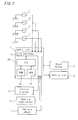
- Fig. 2 is a block diagram illustrating an electric configuration of the detection system shown in Fig. 1 .
- a detection system includes, in order to detect the rotation speeds of four tires provided in a four-wheel vehicle (a left front wheel (FL), a right front wheel (FR), a left rear wheel (RL), and a right rear wheel (RR)), a normal wheel speed detection means (rotation speed information detection means) 1 provided to be associated with the respective tires.
- a four-wheel vehicle a left front wheel (FL), a right front wheel (FR), a left rear wheel (RL), and a right rear wheel (RR)
- a normal wheel speed detection means rotation speed information detection means
- the wheel speed sensor 1 may be, for example, a wheel speed sensor that uses an electromagnetic pickup for example to generate a rotation pulse to measure a rotation angle speed and a wheel speed based on the number of pulses or an angular velocity sensor such as the one that generates power using rotation as in a dynamo to measure a rotation angle speed and a wheel speed based on this voltage.
- the output from the wheel speed sensor 1 is given to a control unit 2 that is a computer such as ABS.
- This control unit 2 is connected to a reset button 3 that can be operated by a driver and an alarm unit 4 for notifying the driver of deflated tires.
- the vehicle is attached with a lateral G sensor 5 for measuring the lateral acceleration acting on the vehicle, a steering angle sensor 6 for measuring the steering angle to the direction along which the vehicle is running, and a yaw rate sensor 7 for measuring the change rate of the rotation angle in the cornering direction of the vehicle.
- a lateral G sensor 5 for measuring the lateral acceleration acting on the vehicle
- a steering angle sensor 6 for measuring the steering angle to the direction along which the vehicle is running
- a yaw rate sensor 7 for measuring the change rate of the rotation angle in the cornering direction of the vehicle.
- the lateral G sensor 5, the steering angle sensor 6, and the yaw rate sensor 7 are not particularly limited in the present invention and may be appropriately selected from among the commercially-available ones.
- the lateral G sensor 5 may be, for example, a piezoelectric-type or strain gauge-type acceleration transducer.
- the steeirng angle sensor 6 may be, for example, a rotation angle meter using a potentiometer attached to the vehicle for example.
- the control unit 2 is composed of: an I/O interface 2a required for the exchange of a signal with an external apparatus; a CPU 2b functioning as a computation processing center; a ROM 2c storing therein a control operation program of the CPU 2b; and a RAM 2d to which data is temporarily written or from which the written data is read out when the CPU 2b performs a control operation.
- the wheel speed sensor 1 outputs a pulse signal corresponding to the rotation number of a tire (hereinafter also referred to as "wheel speed pulse”).
- the detection system is composed of: the wheel speed sensor 1; a rotation speed calculation means for calculating, based on the wheel speed pulse obtained from the wheel speed sensor 1, rotation speeds of the tires; and a determination means for comparing a decreased pressure determination value using the calculated rotation speeds with a predetermined threshold value to determine deflated tires.
- the determination means determines that the vehicle is going straight when it is found, with regard to factors composed of a lateral G, a yaw rate, and a steering angle of the vehicle, at least two of the factors including the yaw rate show that a difference between the maximum value and the minimum value at a predetermined time is lower than a predetermined value, thereby determining deflated tires.
- the detection system further includes a calibration means for calculating a correction value to correct the rotation speeds of the respective tires with normal pressure.
- the calibration means is so configured as to determine that the vehicle is going straight when it is found, with regard to factors composed of a lateral G, a yaw rate, and a steering angle of the vehicle, at least two of the factors including the yaw rate show that a difference between the maximum value and the minimum value at a predetermined time is lower than a predetermined value, thereby performing calibration.
- a program according to the present embodiment is installed in the control unit 2 and causes the control unit 2 to function as the rotation speed calculation means, the determination means, and the calibration means.
- Tires attached to a vehicle do not always have an identical size. Furthermore, even tires having an identical size are manufactured to include tolerance within a standard. Thus, the respective tires do not always have an identical rolling radius (a value obtained by dividing the distance traveled by one rotation by 2n) even when all of the tires are at normal pressure, thus resulting in the respective tires having various rotational angular velocities Fi. To solve this, it is required to correct in advance the variation of the rotational angular velocities Fi among the respective tires at a normal pressure for example. This correction is generally called calibration and is carried out based on the following method for example when the vehicle tires are set to have a normal pressure by a periodic maintenance. According to this method, the following initial correction coefficients K1, K2, and K3 are calculated.
- K ⁇ 1 F ⁇ 1 / F ⁇ 2
- K ⁇ 2 F ⁇ 3 / F ⁇ 4
- K ⁇ 3 F ⁇ 1 + K ⁇ 1 ⁇ F ⁇ 2 / F ⁇ 2 + K ⁇ 2 ⁇ F ⁇ 4
- F ⁇ 1 3 K ⁇ 3 ⁇ F ⁇ 3
- F ⁇ 1 4 K ⁇ 2 ⁇ K ⁇ 3 ⁇ F ⁇ 4
- the initial correction coefficient K1 is a coefficient to correct the difference in the effective rolling radius due to the initial difference between the front left and right tires.
- the initial correction coefficient K2 is a coefficient to correct the difference in the effective rolling radius due to the initial difference between the rear left and right tires.
- the initial correction coefficient K3 is a coefficient to correct the difference in the effective rolling radius due to the initial difference between the front left tire and the rear left tire.
- the calibration as described above is so configured as to determine that the vehicle is going straight when it is found, with regard to factors composed of a lateral G, a yaw rate, and a steering angle of the vehicle measured by the sensors 5, 6 and 7, at least two of the factors including the yaw rate show that a difference between the maximum value and the minimum value at a predetermined time is lower than a predetermined value, thereby performing initialization.
- the outputs from the lateral G sensor 5, the steering angle sensor 6, and the yaw rate sensor 7 are given to the control unit 2 at every 20ms for example.
- the CPU 2b of the control unit 2 calculates an average value of the measurement values within a period of 1 second for example to sequentially cause the RAM 2d to store the average value. Then, the CPU 2b of the control unit 2 determines that the vehicle is going straight when a difference between the maximum value and the minimum value of the respective measurement values within a period of 30 seconds for example is lower than a "predetermined value".
- the "predetermined value" of the lateral G can be, for example, within a range from 0.01 to 0.2(G) and preferably within a range from 0.03 to 0.09 (G) .
- the "predetermined value" of the yaw rate can be, for example, within a range from 0.5 to 8 (deg/sec) and preferably within a range from 3 to 5 (deg/sec) .
- the "predetermined value” of the steering angle can be, for example, within a range from 0.5 to 15(deg) and preferably within a range from 5 to 9(deg).
- the predetermined time for the determination can be, for example, 1 to 60 seconds.
- the unit time for calculating an average value can be 40ms to 1 second. When an output from the sensor is given at every 20ms and the unit time is 40ms, an average value of two outputs is calculated.
- another method also may be used to calculate a difference between the maximum value and the minimum value based on the respective outputs (pulses) from the lateral G sensor 5, the steering angle sensor 6, and the yaw rate sensor 7.
- the calibration means determines that the vehicle is not going straight and thus does not perform the calibration.
- the calculation of the tire rotation speed by the rotation speed calculation means is suspended for a fixed period of time (e.g., about 15 seconds).
- cornering may be determined again with a high possibility.
- a computer for the detection system installed in the vehicle can use the computational resource effectively.
- the rotational angular velocity Fi acquired during driving is corrected based on the formulae (4) to (7) for example. Then, the corrected rotational angular velocity is used to calculate the tire decreased pressure determination value DEL.
- F1 to F4 mean the rotational angular velocities of a left front tire (FL), a right front tire (FR), a left rear tire (RL), and a right rear tire (RR), respectively.
- the calculated decreased pressure determination value DEL is compared with a predetermined threshold value that is calculated by an experiment running for example in advance and that is stored in the ROM 2c of the control unit 2.
- a predetermined threshold value that is calculated by an experiment running for example in advance and that is stored in the ROM 2c of the control unit 2.
- the decreased pressure determination must be performed while a predetermined going straight is maintained in order to avoid a false warning or no warning.
- the detection means for performing the decreased pressure determination as described above is so configured as to determine that the vehicle is going straight when it is found, with regard to factors composed of a lateral G, a yaw rate, and a steering angle of the vehicle measured by the sensor, at least two of the factors including the yaw rate show that a difference between the maximum value and the minimum value at a predetermined time is lower than a predetermined value, thereby determining deflated tires.
- the outputs from the lateral G sensor 5, the rudder angle sensor 6, and the yaw rate sensor 7 are given to the control unit 2 at every 20ms for example.
- the CPU 2b of the control unit 2 calculates an average value of the measurement values within a period of 1 second for example to sequentially cause the RAM 2d to store this average value. Then, the CPU 2b of the control unit 2 determines that the vehicle is going straight when a difference between the maximum value and the minimum value of the respective measurement values within a period of 30 seconds for example is lower than a "predetermined value".
- An FWD (front wheel drive) vehicle was attached with summer 16 inche tires. Then, the vehicle was allowed to drive on a general road to perform going straight and cornering.
- the vehicle was equipped with a yaw rate sensor, a lateral G sensor, and a steering angle sensor.
- the measurement values from these sensors were measured in actual vehicle.
- the respective sensors output measurement values at every 40ms to the control unit mounted in the vehicle.
- the control unit there was installed a program for determining that the vehicle is going straight when a difference between the maximum value and the minimum value of the yaw rate value, the lateral G value, and the steering angle value at every 1 second within a period of 30 seconds is lower than a yaw rate value of 4 (deg/sec), a lateral G of 0.07(G), and a steering angle value of 7(deg).
- Fig. 3 to Fig. 5 illustrate a change in the yaw rate value, the lateral G value, and the steering angle value during the test, respectively.
- the part enclosed by the chain double dashed line shows a part where an actual going straight was performed.
- the test result shows that it was also correctly determined that the part enclosed by the chain double dashed line is the part where the going straight was performed.
Abstract
Description
- The present invention relates to a system, a method, and a program for detecting deflated tires. More particularly, the present invention relates to a system, a method, and a program for detecting deflated tires using the rotation speed information of tires attached to a running vehicle.
- Conventionally, there has been a system for detecting a deflated tires based on the rotation speed (wheel speed) sensor information. This system uses a principle according to which deflated tires show a reduced outer diameter (tire dynamic loaded radius) compared to that of tires with a normal air pressure (reference pressure) and thus show an increased rotation speed and an increased rotation angle speed compared to those of other normal pressure tires. In case of a method of detecting deflated tires based on a relative difference in the rotational angular velocity of tires (see
Patent Literature 1 for example) for example, a determination value DEL obtained by
is used. In the formula, F1 to F4 represent rotational angular velocities of a left front tire, a right front tire, a left rear tire, and a right rear tire, respectively. - By the way, a tire dynamic loaded radius is influenced by factors other than a decreased pressure (e.g., tire load shift during cornering) . Thus, in order to correctly determine deflated tires, a decreased pressure must be determined based on the tire rotation information that is obtained when the vehicle is not cornering (i.e., that is obtained during going straight). This also applies to system calibration when the tire air pressure is adjusted to a normal pressure or a tire is exchanged with a new one. Thus, calibration must be performed based on the tire rotation information during going straight.
-
Patent Literature 2 discloses, in order to improve the calibration accuracy as described above, a technique to monitor a vehicle lateral acceleration (lateral G) and a steering angle to perform calibration based only on the rotational angular velocity data that is obtained when the lateral acceleration and the steering angle are within a predetermined range. -
- {PTL1} Japanese Unexamined Patent Publication No.
1988-305011 - {PTL2} Japanese Unexamined Patent Publication No.
1994-183227 - However, the lateral G sensor for measuring the lateral G is influenced by a road surface cant. Thus, 0G cannot be measured even during going straight. Furthermore, a steering angle sensor for measuring a steering angle includes significant play and thus may not be able to measure 0° even during going straight, thus falsely determining going straight.
- The present invention has been made in view of the situation as described above. It is an objective of the present invention to provide a system, a method, and a program for detecting deflated tires by which the vehicle under going straight can be determined with an improved accuracy.
-
- (1) In accordance with the present invention, there is provided a system for detecting deflated tires (hereinafter also may be simply referred to as "detection system") by making a relative comparison among rotation speeds of tires attached to a vehicle, including:
- a rotation speed information detection means for detecting rotation speed information of the tires;
- a rotation speed calculation means for calculating, based on the rotation speed information obtained from the rotation speed information detection means, rotation speeds of the tires; and
- a determination means for determining deflated tires comparing a decreased pressure determination value using the calculated rotation speeds with a predetermined threshold value,
factors composed of a lateral G, a yaw rate, and a steering angle of the vehicle, at least two of the factors including the yaw rate show that a difference between the maximum value and the minimum value at a predetermined time is lower than a predetermined value, thereby determining deflated tires.
According to the detection system of the present invention, it is determined that the vehicle is going straight when it is found, with regard to factors composed of a lateral G, a yaw rate, and a steering angle of the vehicle, at least two of the factors including the yaw rate show that a difference between the maximum value and the minimum value at a predetermined time is lower than a predetermined value. The yaw rate value is not influenced by the road surface cant influencing on the lateral G sensor or the allowance included in the steering angle sensor. Thus, by use of the yaw rate value as information to determine the vehicle is going straight or not, the determination can be made with an improved accuracy. The yaw rate value or the like is evaluated based not on the absolute value but on the comparison of a difference between the maximum value and the minimum value at a predetermined time and a predetermined value. Thus, even when the value is offset, the going straight can be determined. - (2) The detection system of (1) may further include a calibration means for calculating a correction value to correct the rotation speeds of the respective tires with normal pressure,
wherein the calibration may be configured to determine that the vehicle is going straight when it is found, with regard to factors composed of a lateral G, a yaw rate, and a steering angle of the vehicle, at least two of the factors including the yaw rate show that a difference between the maximum value and the minimum value at a predetermined time is lower than a predetermined value, thereby performing calibration.
Calibration is also performed by determining that the vehicle is going straight when it is found, with regard to factors composed of a lateral G, a yaw rate, and a steering angle of the vehicle, at least two of the factors including the yaw rate show that a difference between the maximum value and the minimum value at a predetermined time is lower than a predetermined value. Thus, the vehicle going straight can be determined with an improved accuracy. - (3) In the detection system of (1) or (2), the maximum value and the minimum value may be an average value at a predetermined unit time.
- (4) In the detection system of (1) to (3), a predetermined value of the lateral G may be a value in the range of 0.03 to 0.09 (G), a predetermined value of the yaw rate may be a value in the range of 3 to 5(deg/sec), and a predetermined value of the steering angle may be a value in the range of 5 to 9 (deg).
- (5) In the detection system of (1) to (4), when the determination means determines that a difference between the maximum value and the minimum value at the predetermined time is equal to or higher than a predetermined value, the calculation of the tire rotation speed by the rotation speed calculation means may be stopped for a fixed period of time. In this way, a computer for the detection system installed in the vehicle can use the computational resource effectively.
- (6) In the detection system of (2) to (5), when the calibration means determines that a difference between the maximum value and the minimum value at the predetermined time is equal to or higher than a predetermined value, the calculation of the tire rotation speed by the rotation speed calculation means can be suspended for a fixed period of time. In this way, a computer for the detection system installed in the vehicle can use the computational resource effectively.
- (7) In accordance with the present invention, there is further provided a method of detecting deflated tires (hereinafter also may be simply referred to as "detection method") by making a relative comparison among rotation speeds of tires attached to a vehicle, including:
- a rotation speed information detection step for detecting rotation speed information of the tires;
- a rotation speed calculation step for calculating, based on the rotation speed information obtained in the rotation speed information detection step, rotation speeds of the tires; and
- a determination step for determining deflated tires by comparing a decreased pressure determination value using the calculated rotation speeds with a predetermined threshold value,
predetermined value, thereby determining deflated tires.
According to the detection method of the present invention, it is determined that the vehicle is going straight when it is found, with regard to factors composed of a lateral G, a yaw rate, and a steering angle of the vehicle, at least two of the factors including the yaw rate show that a difference between the maximum value and the minimum value at a predetermined time is lower than a predetermined value. The yaw rate value is not influenced by the road surface cant influencing on the lateral G sensor or the play included in the steering angle sensor. Thus, by use of the yaw rate value as information to determine the vehicle is going straight or not, the determination can be made with an improved accuracy. The yaw rate value or the like is evaluated based not on the absolute value but on the comparison of a difference between the maximum value and the minimum value at a predetermined time and a predetermined value. Thus, even when the value is offset, the going straight can be determined. - (8) The detection method of (7) may further include a calibration step for calculating a correction value to correct the rotation speeds of the respective tires with normal pressure,
wherein the calibration step may be configured to determine that the vehicle is going straight when it is found, with regard to factors composed of a lateral G, a yaw rate, and a steering angle of the vehicle, at least two of the factors including the yaw rate show that a difference between the maximum value and the minimum value at a predetermined time is lower than a predetermined value, thereby performing calibration.
Calibration is also performed by determination that the vehicle is going straight when it is found, with regard to factors composed of a lateral G, a yaw rate, and a steering angle of the vehicle, at least two of the factors including the yaw rate show that a difference between the maximum value and the minimum value at a predetermined time is lower than a predetermined value. Thus, the vehicle going straight can be determined with an improved accuracy. - (9) In the detection method of (7) or (8), the maximum value and the minimum value may be an average value at a predetermined unit time.
- (10) In the detection method of (7) to (9), a predetermined value of the lateral G may be a value in the range of 0.03 to 0.09(G), a predetermined value of the yaw rate may be a value in the range of 3 to 5 (deg/sec), and a predetermined value of the steering angle may be a value in the range of 5 to 9 (deg).
- (11) In the detection method of (7) to (10), when the determination step determines that a difference between the maximum value and the minimum value at the predetermined time is equal to or higher than a predetermined value, the calculation of the tire rotation speed by the rotation speed calculation step may be suspended for a fixed period of time. In this way, a computer for the detection system installed in the vehicle can use the computational resource effectively.
- (12) In the detection method of (8) to (11), when the calibration step determines that a difference between the maximum value and the minimum value at the predetermined time is equal to or higher than a predetermined value, the calculation of the tire rotation speed by the rotation speed calculation step can be suspended for a fixed period of time. In this way, a computer for the detection system installed in the vehicle can use the computational resource effectively.
- (13) In accordance with the present invention, there is also provided a program for detecting deflated tires (hereinafter also may be simply referred to as "program") for causing, in order to detect deflated tires by making a relative comparison among rotation speeds of tires attached to a vehicle, a computer to function as:
- a rotation speed calculation means for calculating rotation speeds of the tires based on rotation speed information obtained from a rotation speed information detection means for detecting rotation speed information of the tires; and
- a determination means for determining deflated tires comparing a decreased pressure determination value using the calculated rotation speeds with a predetermined threshold value,
- (14) In the program of (13), the computer may be further caused to function as a calibration for calculating a correction value to correct the rotation speeds of the respective tires when the tires with normal pressure, and
wherein the calibration means may be configured to determine that the vehicle is going straight when it is found, with regard to factors composed of a lateral G, a yaw rate, and a steering angle of the vehicle, at least two of the factors including the yaw rate show that a difference between the maximum value and the minimum value at a predetermined time is lower than a predetermined value, thereby performing calibration. - (15) In the program of (13) or (14), the maximum value and the minimum value may be an average value at a predetermined unit time.
- (16) In the program of (13) to (15), a predetermined value of the lateral G may be a value in the range of 0.03 to 0.09 (G), a predetermined value of the yaw rate may be a value in the range of 3 to 5 (deg/sec), and a predetermined value of the rudder angle may be a value in the range of 5 to 9(deg).
- (17) In the program of (13) to (16), when the determination means determines that a difference between the maximum value and the minimum value at the predetermined time is equal to or higher than a predetermined value, the calculation of the tire rotation speed by the rotation speed calculation means may be suspended for a fixed period of time.
- (18) In the program of (13) to (16), when the calibration means determines that a difference between the maximum value and the minimum value at the predetermined time is equal to or higher than a predetermined value, the calculation of the tire rotation speed by the rotation speed calculation means can be suspended for a fixed period of time.
- According to the detection system, the detection method, and the detection program of the present invention, the vehicle going straight can be determined with an improved accuracy.
-
-
Fig. 1 is a block diagram illustrating one embodiment of a detection system of the present invention; -
Fig. 2 is a block diagram illustrating an electric configuration of the detection system shown inFig. 1 ; -
Fig. 3 illustrates a change of the yaw rate value during a test; -
Fig. 4 illustrates a change of the lateral G value during a test; and -
Fig. 5 illustrates a change of the steering angle value during a test. - Hereinafter, with reference to the attached drawings, an embodiment of a detection system, a method, and a program of the present invention will be described in detail.
Fig. 1 is a block diagram illustrating one embodiment of a detection system of the present invention, andFig. 2 is a block diagram illustrating an electric configuration of the detection system shown inFig. 1 . - As shown in
Fig. 1 , a detection system according to one embodiment of the present invention includes, in order to detect the rotation speeds of four tires provided in a four-wheel vehicle (a left front wheel (FL), a right front wheel (FR), a left rear wheel (RL), and a right rear wheel (RR)), a normal wheel speed detection means (rotation speed information detection means) 1 provided to be associated with the respective tires. - The
wheel speed sensor 1 may be, for example, a wheel speed sensor that uses an electromagnetic pickup for example to generate a rotation pulse to measure a rotation angle speed and a wheel speed based on the number of pulses or an angular velocity sensor such as the one that generates power using rotation as in a dynamo to measure a rotation angle speed and a wheel speed based on this voltage. The output from thewheel speed sensor 1 is given to acontrol unit 2 that is a computer such as ABS. Thiscontrol unit 2 is connected to areset button 3 that can be operated by a driver and analarm unit 4 for notifying the driver of deflated tires. - The vehicle is attached with a lateral G sensor 5 for measuring the lateral acceleration acting on the vehicle, a
steering angle sensor 6 for measuring the steering angle to the direction along which the vehicle is running, and ayaw rate sensor 7 for measuring the change rate of the rotation angle in the cornering direction of the vehicle. These components are attached at appropriate positions. The outputs from the lateral G sensor 5, thesteering angle sensor 6, and theyaw rate sensor 7 are also given to thecontrol unit 2. - The lateral G sensor 5, the
steering angle sensor 6, and theyaw rate sensor 7 are not particularly limited in the present invention and may be appropriately selected from among the commercially-available ones. The lateral G sensor 5 may be, for example, a piezoelectric-type or strain gauge-type acceleration transducer. Thesteeirng angle sensor 6 may be, for example, a rotation angle meter using a potentiometer attached to the vehicle for example. - As shown in
Fig. 2 , thecontrol unit 2 is composed of: an I/O interface 2a required for the exchange of a signal with an external apparatus; aCPU 2b functioning as a computation processing center; aROM 2c storing therein a control operation program of theCPU 2b; and aRAM 2d to which data is temporarily written or from which the written data is read out when theCPU 2b performs a control operation. - The
wheel speed sensor 1 outputs a pulse signal corresponding to the rotation number of a tire (hereinafter also referred to as "wheel speed pulse"). TheCPU 2b calculates, based on the wheel speed pulse outputted from thewheel speed sensor 1 and at every predetermined sampling cycle ΔT (ms) (e.g., ΔT = 20 to 40ms), the rotational angular velocity Fi that shows the information for the rotation speeds of the respective tires. - The detection system according to the present embodiment is composed of: the
wheel speed sensor 1; a rotation speed calculation means for calculating, based on the wheel speed pulse obtained from thewheel speed sensor 1, rotation speeds of the tires; and a determination means for comparing a decreased pressure determination value using the calculated rotation speeds with a predetermined threshold value to determine deflated tires. The determination means determines that the vehicle is going straight when it is found, with regard to factors composed of a lateral G, a yaw rate, and a steering angle of the vehicle, at least two of the factors including the yaw rate show that a difference between the maximum value and the minimum value at a predetermined time is lower than a predetermined value, thereby determining deflated tires. - The detection system according to the present embodiment further includes a calibration means for calculating a correction value to correct the rotation speeds of the respective tires with normal pressure. The calibration means is so configured as to determine that the vehicle is going straight when it is found, with regard to factors composed of a lateral G, a yaw rate, and a steering angle of the vehicle, at least two of the factors including the yaw rate show that a difference between the maximum value and the minimum value at a predetermined time is lower than a predetermined value, thereby performing calibration.
- A program according to the present embodiment is installed in the
control unit 2 and causes thecontrol unit 2 to function as the rotation speed calculation means, the determination means, and the calibration means. - Tires attached to a vehicle do not always have an identical size. Furthermore, even tires having an identical size are manufactured to include tolerance within a standard. Thus, the respective tires do not always have an identical rolling radius (a value obtained by dividing the distance traveled by one rotation by 2n) even when all of the tires are at normal pressure, thus resulting in the respective tires having various rotational angular velocities Fi. To solve this, it is required to correct in advance the variation of the rotational angular velocities Fi among the respective tires at a normal pressure for example. This correction is generally called calibration and is carried out based on the following method for example when the vehicle tires are set to have a normal pressure by a periodic maintenance. According to this method, the following initial correction coefficients K1, K2, and K3 are calculated.


- During the driving after the calibration, the calculated initial correction coefficients K1, K2, and K3 are used to calculate a new rotational angular velocity F1i as shown in the formulae (4) to (7).


- In the formulae, the initial correction coefficient K1 is a coefficient to correct the difference in the effective rolling radius due to the initial difference between the front left and right tires. The initial correction coefficient K2 is a coefficient to correct the difference in the effective rolling radius due to the initial difference between the rear left and right tires. The initial correction coefficient K3 is a coefficient to correct the difference in the effective rolling radius due to the initial difference between the front left tire and the rear left tire.
- When this calibration is performed during the vehicle cornering, an improper correction coefficient is calculated. Thus, the calibration must be performed when a predetermined going straight is maintained.
- In the present embodiment, the calibration as described above is so configured as to determine that the vehicle is going straight when it is found, with regard to factors composed of a lateral G, a yaw rate, and a steering angle of the vehicle measured by the
sensors - The outputs from the lateral G sensor 5, the
steering angle sensor 6, and theyaw rate sensor 7 are given to thecontrol unit 2 at every 20ms for example. TheCPU 2b of thecontrol unit 2 calculates an average value of the measurement values within a period of 1 second for example to sequentially cause theRAM 2d to store the average value. Then, theCPU 2b of thecontrol unit 2 determines that the vehicle is going straight when a difference between the maximum value and the minimum value of the respective measurement values within a period of 30 seconds for example is lower than a "predetermined value". - The "predetermined value" of the lateral G can be, for example, within a range from 0.01 to 0.2(G) and preferably within a range from 0.03 to 0.09 (G) . The "predetermined value" of the yaw rate can be, for example, within a range from 0.5 to 8 (deg/sec) and preferably within a range from 3 to 5 (deg/sec) . The "predetermined value" of the steering angle can be, for example, within a range from 0.5 to 15(deg) and preferably within a range from 5 to 9(deg).
- The predetermined time for the determination can be, for example, 1 to 60 seconds. The unit time for calculating an average value can be 40ms to 1 second. When an output from the sensor is given at every 20ms and the unit time is 40ms, an average value of two outputs is calculated.
- In addition to the method of calculating an average value at the predetermined unit time and obtaining a difference between the maximum value and the minimum value by using a plurality of average values within the predetermined time, another method also may be used to calculate a difference between the maximum value and the minimum value based on the respective outputs (pulses) from the lateral G sensor 5, the
steering angle sensor 6, and theyaw rate sensor 7. - When it is found, with regard to factors composed of a lateral G, a yaw rate, and a steering angle of the vehicle, at least two of the factors including the yaw rate show that a difference between the maximum value and the minimum value is equal to or higher than a "predetermined value", the calibration means determines that the vehicle is not going straight and thus does not perform the calibration. In the present embodiment, when the determination as described is made, the calculation of the tire rotation speed by the rotation speed calculation means is suspended for a fixed period of time (e.g., about 15 seconds). When it is determined at a predetermined time that the vehicle is not going straight, this cornering may continue, with a high possibility, for a certain period depending on the length of the predetermined time. Thus, even when the determination of the cornering is immediately reset to calculate the average value and a difference between the maximum value and the minimum value immediately, cornering may be determined again with a high possibility. To prevent this, by suspend of the calculation of the tire rotation speed for a fixed period of time, a computer for the detection system installed in the vehicle can use the computational resource effectively.
- With regard to the vehicle subjected to the calibration, the rotational angular velocity Fi acquired during driving is corrected based on the formulae (4) to (7) for example. Then, the corrected rotational angular velocity is used to calculate the tire decreased pressure determination value DEL. This decreased pressure determination value DEL is not particularly limited in the present invention and may be conventionally-suggested ones by a conventional method of using the tire rotation speed information to detect deflated tires. For example, the following formula can be used.

- In the formula, F1 to F4 mean the rotational angular velocities of a left front tire (FL), a right front tire (FR), a left rear tire (RL), and a right rear tire (RR), respectively.
- Then, the calculated decreased pressure determination value DEL is compared with a predetermined threshold value that is calculated by an experiment running for example in advance and that is stored in the
ROM 2c of thecontrol unit 2. When the DEL is higher than the threshold value, deflated tires are determined. - Also in the decreased pressure determination as described above, as in the above-described calibration, the decreased pressure determination must be performed while a predetermined going straight is maintained in order to avoid a false warning or no warning.
- In the present embodiment, the detection means for performing the decreased pressure determination as described above is so configured as to determine that the vehicle is going straight when it is found, with regard to factors composed of a lateral G, a yaw rate, and a steering angle of the vehicle measured by the sensor, at least two of the factors including the yaw rate show that a difference between the maximum value and the minimum value at a predetermined time is lower than a predetermined value, thereby determining deflated tires.
- The outputs from the lateral G sensor 5, the
rudder angle sensor 6, and theyaw rate sensor 7 are given to thecontrol unit 2 at every 20ms for example. TheCPU 2b of thecontrol unit 2 calculates an average value of the measurement values within a period of 1 second for example to sequentially cause theRAM 2d to store this average value. Then, theCPU 2b of thecontrol unit 2 determines that the vehicle is going straight when a difference between the maximum value and the minimum value of the respective measurement values within a period of 30 seconds for example is lower than a "predetermined value". - What has been described in the above paragraphs regarding the "predetermined value" and "predetermined time" for example in relation to the calibration also applies to the decreased pressure determination. The following description will not repeat the above description for simplicity.
- An FWD (front wheel drive) vehicle was attached with summer 16 inche tires. Then, the vehicle was allowed to drive on a general road to perform going straight and cornering.
- The vehicle was equipped with a yaw rate sensor, a lateral G sensor, and a steering angle sensor. The measurement values from these sensors were measured in actual vehicle. The respective sensors output measurement values at every 40ms to the control unit mounted in the vehicle. In the control unit, there was installed a program for determining that the vehicle is going straight when a difference between the maximum value and the minimum value of the yaw rate value, the lateral G value, and the steering angle value at every 1 second within a period of 30 seconds is lower than a yaw rate value of 4 (deg/sec), a lateral G of 0.07(G), and a steering angle value of 7(deg).
- The result is shown in
Fig. 3 to Fig. 5. Fig. 3 to Fig. 5 illustrate a change in the yaw rate value, the lateral G value, and the steering angle value during the test, respectively. In the drawings, the part enclosed by the chain double dashed line shows a part where an actual going straight was performed. The test result shows that it was also correctly determined that the part enclosed by the chain double dashed line is the part where the going straight was performed. - In the present test, it is determined that the vehicle is going straight when all of the yaw rate value, the lateral G value, and the steering angle value are lower than the predetermined value. As can be seen from
Fig. 3 to Fig. 5 , when the yaw rate value and the lateral G value are lower than the predetermined value and when the yaw rate value and the steering angle value are lower than the predetermined value, it is possible to determine that the part enclosed by the chain double dashed line is the part where the going straight was performed. -
- 1
- Wheel speed sensor
- 2
- Control unit
- 2a
- Interface
- 2b
- CPU
- 2c
- ROM
- 2d
- RAM
- 3
- Reset button
- 4
- Warning unit
- 5
- Lateral G sensor
- 6
- Steering angle sensor
- 7
- Yaw rate sensor
Claims (18)
- A system for detecting deflated tires by making a relative comparison among rotation speeds of tires attached to a vehicle, comprising:a rotation speed information detection means for detecting rotation speed information of the tires;a rotation speed calculation means for calculating, based on the rotation speed information obtained from the rotation speed information detection means, rotation speeds of the tires; anda determination means for determining deflated tires by comparing a decreased pressure determination value using the calculated rotation speeds with a predetermined threshold value,wherein the determination means determines that the vehicle is going straight when it is found, with regard to factors composed of a lateral G, a yaw rate, and a steering angle of the vehicle, at least two of the factors including the yaw rate show that a difference between the maximum value and the minimum value at a predetermined time is lower than a predetermined value, thereby determining deflated tires.
- The system according to claim 1, further comprising a calibration means for calculating a correction value to correct the rotation speeds of the respective tires with normal pressure,
wherein the calibration means is configured to determine that the vehicle is going straight when it is found, with regard to factors composed of a lateral G, a yaw rate, and a steering angle of the vehicle, at least two of the factors including the yaw rate show that a difference between the maximum value and the minimum value at a predetermined time is lower than a predetermined value, thereby performing calibration. - The system according to claim 1 or claim 2, wherein the maximum value and the minimum value is an average value at a predetermined unit time.
- The system according to any one of claims 1 to 3, wherein a predetermined value of the lateral G is a value in the range of 0.03 to 0.09(G), a predetermined value of the yaw rate is a value in the range of 3 to 5(deg/sec), and a predetermined value of the steering angle is a value in the range of 5 to 9 (deg).
- The system according to any one of claims 1 to 4, wherein, when the determination means determines that a difference between the maximum value and the minimum value at the predetermined time is equal to or higher than a predetermined value, the calculation of the tire rotation speed by the rotation speed calculation means is suspended for a fixed period of time.
- The system according to any one of claims 2 to 5, wherein, when the calibration means determines that a difference between the maximum value and the minimum value at the predetermined time is equal to or higher than a predetermined value, the calculation of the tire rotation speed is suspended for a fixed period of time.
- A method of detecting deflated tires by making a relative comparison among rotation speeds of tires attached to a vehicle, including:a rotation speed information detection step for detecting rotation speed information of the tires;a rotation speed calculation step for calculating, based on the rotation speed information obtained in the rotation speed information detection step, rotation speeds of the tires; anda determination step for determining deflated tires by comparing a decreased pressure determination value using the calculated rotation speeds with a predetermined threshold value,wherein the determination step determines that the vehicle is going straight when it is found, with regard to factors composed of a lateral G, a yaw rate, and a steering angle of the vehicle, at least two of the factors including the yaw rate show that a difference between the maximum value and the minimum value at a predetermined time is lower than a predetermined value, thereby determining deflated tires.
- The method according to claim 7, further comprising an calibration step for calculating a correction value to correct the rotation speeds of the respective tires with normal pressure,
wherein the calibration step is configured to determine that the vehicle is going straight when it is found, with regard to factors composed of a lateral G, a yaw rate, and a steering angle of the vehicle, at least two of the factors including the yaw rate show that a difference between the maximum value and the minimum value at a predetermined time is lower than a predetermined value, thereby performing calibration. - The method according to claim 7 or claim 8, wherein the maximum value and the minimum value is an average value at a predetermined unit time.
- The method according to any one of claims 7 to 9, wherein a predetermined value of the lateral G is a value in the range of 0.03 to 0.09(G), a predetermined value of the yaw rate is a value in the range of 3 to 5(deg/sec), and a predetermined value of the steering angle is a value in the range of 5 to 9 (deg).
- The method according to any one of claims 7 to 10, wherein, when the determination step determines that a difference between the maximum value and the minimum value at the predetermined time is equal to or higher than a predetermined value, the calculation of the tire rotation speed is suspended for a fixed period of time.
- The method according to any one of claims 8 to 11, wherein, when the calibration step determines that a difference between the maximum value and the minimum value at the predetermined time is equal to or higher than a predetermined value, the calculation of the tire rotation speed is suspended for a fixed period of time.
- A program for detecting deflated tires for causing, in order to detect deflated tires by making a relative comparison among rotation speeds of tires attached to a vehicle, a computer to function as:a rotation speed calculation means for calculating rotation speeds of the tires based on rotation speed information obtained from a rotation speed information detection means for detecting rotation speed information of the tires; anda determination means for comparing a decreased pressure determination value using the calculated rotation speeds with a predetermined threshold value to determine deflated tires,wherein the determination means determines that the vehicle is going straight when it is found, with regard to factors composed of a lateral G, a yaw rate, and a steering angle of the vehicle, at least two of the factors including the yaw rate show that a difference between the maximum value and the minimum value at a predetermined time is lower than a predetermined value, thereby determining deflated tires.
- The program according to claim 13, wherein the computer is further caused to function as a calibration means for calculating a correction value to correct the rotation speeds of the respective tires with normal pressure, and
wherein the calibration means is configured to determine that the vehicle is going straight when it is found, with regard to factors composed of a lateral G, a yaw rate, and a steering angle of the vehicle, at least two of the factors including the yaw rate show that a difference between the maximum value and the minimum value at a predetermined time is lower than a predetermined value, thereby performing calibration. - The program according to claim 13 or claim 14, wherein the maximum value and the minimum value is an average value at a predetermined unit time.
- The program according to any one of claims 13 to 15, wherein a predetermined value of the lateral G is a value in the range of 0.03 to 0.09(G), a predetermined value of the yaw rate is a value in the range of 3 to 5(deg/sec), and a predetermined value of the steering angle is a value in the range of 5 to 9 (deg).
- The program according to any one of claims 13 to 16, wherein, when the determination means determines that a difference between the maximum value and the minimum value at the predetermined time is equal to or higher than a predetermined value, the calculation of the tire rotation speed is suspended for a fixed period of time.
- The program according to any one of claims 14 to 17, wherein, when the calibration means determines that a difference between the maximum value and the minimum value at the predetermined time is equal to or higher than a predetermined value, the calculation of the tire rotation speed is suspended for a fixed period of time.
Applications Claiming Priority (1)
| Application Number | Priority Date | Filing Date | Title |
|---|---|---|---|
| JP2011125077A JP5383746B2 (en) | 2011-06-03 | 2011-06-03 | Tire pressure drop detection device, method and program |
Publications (3)
| Publication Number | Publication Date |
|---|---|
| EP2529958A2 true EP2529958A2 (en) | 2012-12-05 |
| EP2529958A3 EP2529958A3 (en) | 2013-09-25 |
| EP2529958B1 EP2529958B1 (en) | 2014-09-10 |
Family
ID=46172703
Family Applications (1)
| Application Number | Title | Priority Date | Filing Date |
|---|---|---|---|
| EP12169472.3A Not-in-force EP2529958B1 (en) | 2011-06-03 | 2012-05-25 | System, method, and program for detecting deflated tires |
Country Status (3)
| Country | Link |
|---|---|
| US (1) | US9387736B2 (en) |
| EP (1) | EP2529958B1 (en) |
| JP (1) | JP5383746B2 (en) |
Cited By (3)
| Publication number | Priority date | Publication date | Assignee | Title |
|---|---|---|---|---|
| WO2016049801A1 (en) * | 2014-09-29 | 2016-04-07 | 林祖宏 | Automobile tire state monitoring system |
| CN105835634A (en) * | 2016-03-24 | 2016-08-10 | 邹红斌 | Method, device and terminal for detecting tyre pressure |
| CN107160955A (en) * | 2017-05-22 | 2017-09-15 | 南宁学院 | A kind of indirect type vehicle tire pressure early warning system based on APP |
Families Citing this family (2)
| Publication number | Priority date | Publication date | Assignee | Title |
|---|---|---|---|---|
| KR101880128B1 (en) * | 2016-12-29 | 2018-07-19 | 이래에이엠에스 주식회사 | Method and apparatus for determining abnormality of tire pressure for vehicles |
| CN108454327B (en) * | 2018-01-26 | 2020-11-20 | 深圳市元征科技股份有限公司 | Tire pressure detection method, device and terminal |
Citations (2)
| Publication number | Priority date | Publication date | Assignee | Title |
|---|---|---|---|---|
| JPS63305011A (en) | 1987-05-13 | 1988-12-13 | Sumitomo Rubber Ind Ltd | Detecting method for pressure reduction tyre for vehicle |
| JPH06183227A (en) | 1992-12-21 | 1994-07-05 | Sumitomo Rubber Ind Ltd | Automatic initial setting in device to detect abnormality of air pressure from change in tire angular velocity |
Family Cites Families (15)
| Publication number | Priority date | Publication date | Assignee | Title |
|---|---|---|---|---|
| JPH0811483B2 (en) * | 1985-09-13 | 1996-02-07 | 日産自動車株式会社 | Vehicle characteristic control device |
| US5710539A (en) * | 1993-12-07 | 1998-01-20 | Sumitomo Electric Industrties, Ltd. | Tire air-pressure reduction detecting apparatus |
| JPH10166821A (en) * | 1996-12-05 | 1998-06-23 | Kayaba Ind Co Ltd | Vehicle traveling balance detector |
| DE19961681A1 (en) * | 1999-04-03 | 2000-10-19 | Continental Teves Ag & Co Ohg | Method and device for pressure loss detection and vehicle dynamics control |
| JP3933982B2 (en) * | 2002-04-25 | 2007-06-20 | 株式会社ジェイテクト | Electric power steering device |
| JP3829934B2 (en) * | 2002-06-27 | 2006-10-04 | トヨタ自動車株式会社 | Vehicle turning characteristic estimation device |
| JP2005007933A (en) * | 2003-06-16 | 2005-01-13 | Honda Motor Co Ltd | Straight running of vehicle judging device |
| JP4446861B2 (en) * | 2004-11-04 | 2010-04-07 | トヨタ自動車株式会社 | Steering system |
| EP1827950B1 (en) * | 2004-12-24 | 2008-05-28 | Continental Teves AG & Co. oHG | Method for determining the ability to enter a parking space and a parking assist device |
| DE102006008156A1 (en) * | 2006-02-22 | 2007-08-23 | Wabco Gmbh | Vehicle`s steering transmission ratio determining method, involves determining steering transmission ratio of vehicle from measurement values in consideration of vehicle parameters during stable speed of vehicle |
| JP5050417B2 (en) * | 2006-06-16 | 2012-10-17 | 日産自動車株式会社 | Vehicle steering control device |
| JP4980774B2 (en) * | 2007-03-30 | 2012-07-18 | 本田技研工業株式会社 | Vehicle travel safety device |
| JP5185792B2 (en) * | 2008-11-28 | 2013-04-17 | 本田技研工業株式会社 | Yaw rate controller |
| US8494708B2 (en) * | 2009-08-24 | 2013-07-23 | Robert Bosch Gmbh | Good checking for vehicle yaw rate sensor |
| US8823504B2 (en) * | 2011-01-27 | 2014-09-02 | Bendix Commercial Vehicle Systems Llc | System and method for adjusting braking pressure |
-
2011
- 2011-06-03 JP JP2011125077A patent/JP5383746B2/en not_active Expired - Fee Related
-
2012
- 2012-05-25 EP EP12169472.3A patent/EP2529958B1/en not_active Not-in-force
- 2012-06-01 US US13/486,388 patent/US9387736B2/en not_active Expired - Fee Related
Patent Citations (2)
| Publication number | Priority date | Publication date | Assignee | Title |
|---|---|---|---|---|
| JPS63305011A (en) | 1987-05-13 | 1988-12-13 | Sumitomo Rubber Ind Ltd | Detecting method for pressure reduction tyre for vehicle |
| JPH06183227A (en) | 1992-12-21 | 1994-07-05 | Sumitomo Rubber Ind Ltd | Automatic initial setting in device to detect abnormality of air pressure from change in tire angular velocity |
Cited By (4)
| Publication number | Priority date | Publication date | Assignee | Title |
|---|---|---|---|---|
| WO2016049801A1 (en) * | 2014-09-29 | 2016-04-07 | 林祖宏 | Automobile tire state monitoring system |
| CN105835634A (en) * | 2016-03-24 | 2016-08-10 | 邹红斌 | Method, device and terminal for detecting tyre pressure |
| CN105835634B (en) * | 2016-03-24 | 2018-05-18 | 邹红斌 | Tire pressure detection method, device and terminal |
| CN107160955A (en) * | 2017-05-22 | 2017-09-15 | 南宁学院 | A kind of indirect type vehicle tire pressure early warning system based on APP |
Also Published As
| Publication number | Publication date |
|---|---|
| EP2529958A3 (en) | 2013-09-25 |
| US9387736B2 (en) | 2016-07-12 |
| JP5383746B2 (en) | 2014-01-08 |
| US20120310590A1 (en) | 2012-12-06 |
| EP2529958B1 (en) | 2014-09-10 |
| JP2012250629A (en) | 2012-12-20 |
Similar Documents
| Publication | Publication Date | Title |
|---|---|---|
| EP2103454B1 (en) | Method and apparatus for detecting decrease in tire air pressure and program for determining decrease in tire air pressure | |
| US8299909B2 (en) | Apparatus, method and program for detecting decrease in tire air pressure including means to reject data | |
| EP2363695B1 (en) | Apparatus, method and programm for vehicle mass estimation | |
| JP4244354B2 (en) | Tire pressure drop warning method, apparatus and program | |
| EP2529958B1 (en) | System, method, and program for detecting deflated tires | |
| JP2010517000A (en) | Method and apparatus for determining vehicle speed | |
| EP2390117B1 (en) | Method and apparatus for detecting tire having decreased internal pressure, and program for detecting tire having decreased internal pressure | |
| EP2384911B1 (en) | Apparatus, method and program for detecting decrease in tire air pressure | |
| US20090261961A1 (en) | Method and apparatus for detecting decrease in tire air pressure and program for determining decrease in tire air pressure | |
| JP2008249523A (en) | Method, device and program for alarming abnormal drop in tire pneumatic pressure | |
| US8387451B2 (en) | Apparatus and method for detecting decrease in tire air pressure and program for detecting decrease in tire air pressure | |
| JP4707642B2 (en) | Tire pressure abnormality detection device, method and program | |
| JP2009006793A (en) | Method, device and program for detecting reduction of tire internal air pressure | |
| JP3971720B2 (en) | Tire pressure drop detection method and apparatus, and tire decompression determination program | |
| JP3167278B2 (en) | Method and apparatus for detecting decrease in tire air pressure | |
| JP3363553B2 (en) | Tire pressure drop detector | |
| JP5025981B2 (en) | Tire dynamic load radius reference value initialization method for detecting tire pressure drop | |
| JPH106725A (en) | Method and device for detecting tire air pressure reduction | |
| EP2380759B1 (en) | Apparatus, method and program for detecting decrease in tire air pressure | |
| JP2005205977A (en) | Tire pneumatic pressure lowering detection method and device, and program of tire decompression determination | |
| JP5560178B2 (en) | Tire pressure drop warning method and apparatus, and tire pressure drop warning program | |
| JPH07179107A (en) | Judging method and detecting device for tire air pressure reduction | |
| JP2002012013A (en) | Tire air pressure drop warning device and method | |
| JP2013028315A (en) | Method and device for identifying tire type, and method, device and program for detecting decrease in tire pneumatic pressure |
Legal Events
| Date | Code | Title | Description |
|---|---|---|---|
| PUAI | Public reference made under article 153(3) epc to a published international application that has entered the european phase |
Free format text: ORIGINAL CODE: 0009012 |
|
| AK | Designated contracting states |
Kind code of ref document: A2 Designated state(s): AL AT BE BG CH CY CZ DE DK EE ES FI FR GB GR HR HU IE IS IT LI LT LU LV MC MK MT NL NO PL PT RO RS SE SI SK SM TR |
|
| AX | Request for extension of the european patent |
Extension state: BA ME |
|
| PUAL | Search report despatched |
Free format text: ORIGINAL CODE: 0009013 |
|
| AK | Designated contracting states |
Kind code of ref document: A3 Designated state(s): AL AT BE BG CH CY CZ DE DK EE ES FI FR GB GR HR HU IE IS IT LI LT LU LV MC MK MT NL NO PL PT RO RS SE SI SK SM TR |
|
| AX | Request for extension of the european patent |
Extension state: BA ME |
|
| RIC1 | Information provided on ipc code assigned before grant |
Ipc: B60C 23/06 20060101AFI20130816BHEP |
|
| 17P | Request for examination filed |
Effective date: 20131127 |
|
| RBV | Designated contracting states (corrected) |
Designated state(s): AL AT BE BG CH CY CZ DE DK EE ES FI FR GB GR HR HU IE IS IT LI LT LU LV MC MK MT NL NO PL PT RO RS SE SI SK SM TR |
|
| GRAP | Despatch of communication of intention to grant a patent |
Free format text: ORIGINAL CODE: EPIDOSNIGR1 |
|
| RAP1 | Party data changed (applicant data changed or rights of an application transferred) |
Owner name: SUMITOMO RUBBER INDUSTRIES, LTD. Owner name: HONDA MOTOR CO., LTD. |
|
| INTG | Intention to grant announced |
Effective date: 20140414 |
|
| GRAS | Grant fee paid |
Free format text: ORIGINAL CODE: EPIDOSNIGR3 |
|
| GRAA | (expected) grant |
Free format text: ORIGINAL CODE: 0009210 |
|
| AK | Designated contracting states |
Kind code of ref document: B1 Designated state(s): AL AT BE BG CH CY CZ DE DK EE ES FI FR GB GR HR HU IE IS IT LI LT LU LV MC MK MT NL NO PL PT RO RS SE SI SK SM TR |
|
| REG | Reference to a national code |
Ref country code: GB Ref legal event code: FG4D |
|
| REG | Reference to a national code |
Ref country code: CH Ref legal event code: EP |
|
| REG | Reference to a national code |
Ref country code: IE Ref legal event code: FG4D |
|
| REG | Reference to a national code |
Ref country code: AT Ref legal event code: REF Ref document number: 686476 Country of ref document: AT Kind code of ref document: T Effective date: 20141015 |
|
| REG | Reference to a national code |
Ref country code: DE Ref legal event code: R096 Ref document number: 602012003023 Country of ref document: DE Effective date: 20141023 |
|
| PG25 | Lapsed in a contracting state [announced via postgrant information from national office to epo] |
Ref country code: SE Free format text: LAPSE BECAUSE OF FAILURE TO SUBMIT A TRANSLATION OF THE DESCRIPTION OR TO PAY THE FEE WITHIN THE PRESCRIBED TIME-LIMIT Effective date: 20140910 Ref country code: GR Free format text: LAPSE BECAUSE OF FAILURE TO SUBMIT A TRANSLATION OF THE DESCRIPTION OR TO PAY THE FEE WITHIN THE PRESCRIBED TIME-LIMIT Effective date: 20141211 Ref country code: ES Free format text: LAPSE BECAUSE OF FAILURE TO SUBMIT A TRANSLATION OF THE DESCRIPTION OR TO PAY THE FEE WITHIN THE PRESCRIBED TIME-LIMIT Effective date: 20140910 Ref country code: LT Free format text: LAPSE BECAUSE OF FAILURE TO SUBMIT A TRANSLATION OF THE DESCRIPTION OR TO PAY THE FEE WITHIN THE PRESCRIBED TIME-LIMIT Effective date: 20140910 Ref country code: NO Free format text: LAPSE BECAUSE OF FAILURE TO SUBMIT A TRANSLATION OF THE DESCRIPTION OR TO PAY THE FEE WITHIN THE PRESCRIBED TIME-LIMIT Effective date: 20141210 Ref country code: FI Free format text: LAPSE BECAUSE OF FAILURE TO SUBMIT A TRANSLATION OF THE DESCRIPTION OR TO PAY THE FEE WITHIN THE PRESCRIBED TIME-LIMIT Effective date: 20140910 |
|
| REG | Reference to a national code |
Ref country code: NL Ref legal event code: VDEP Effective date: 20140910 |
|
| REG | Reference to a national code |
Ref country code: LT Ref legal event code: MG4D |
|
| PG25 | Lapsed in a contracting state [announced via postgrant information from national office to epo] |
Ref country code: LV Free format text: LAPSE BECAUSE OF FAILURE TO SUBMIT A TRANSLATION OF THE DESCRIPTION OR TO PAY THE FEE WITHIN THE PRESCRIBED TIME-LIMIT Effective date: 20140910 Ref country code: CY Free format text: LAPSE BECAUSE OF FAILURE TO SUBMIT A TRANSLATION OF THE DESCRIPTION OR TO PAY THE FEE WITHIN THE PRESCRIBED TIME-LIMIT Effective date: 20140910 Ref country code: RS Free format text: LAPSE BECAUSE OF FAILURE TO SUBMIT A TRANSLATION OF THE DESCRIPTION OR TO PAY THE FEE WITHIN THE PRESCRIBED TIME-LIMIT Effective date: 20140910 Ref country code: HR Free format text: LAPSE BECAUSE OF FAILURE TO SUBMIT A TRANSLATION OF THE DESCRIPTION OR TO PAY THE FEE WITHIN THE PRESCRIBED TIME-LIMIT Effective date: 20140910 |
|
| REG | Reference to a national code |
Ref country code: AT Ref legal event code: MK05 Ref document number: 686476 Country of ref document: AT Kind code of ref document: T Effective date: 20140910 |
|
| PG25 | Lapsed in a contracting state [announced via postgrant information from national office to epo] |
Ref country code: NL Free format text: LAPSE BECAUSE OF FAILURE TO SUBMIT A TRANSLATION OF THE DESCRIPTION OR TO PAY THE FEE WITHIN THE PRESCRIBED TIME-LIMIT Effective date: 20140910 |
|
| PG25 | Lapsed in a contracting state [announced via postgrant information from national office to epo] |
Ref country code: RO Free format text: LAPSE BECAUSE OF FAILURE TO SUBMIT A TRANSLATION OF THE DESCRIPTION OR TO PAY THE FEE WITHIN THE PRESCRIBED TIME-LIMIT Effective date: 20140910 Ref country code: SK Free format text: LAPSE BECAUSE OF FAILURE TO SUBMIT A TRANSLATION OF THE DESCRIPTION OR TO PAY THE FEE WITHIN THE PRESCRIBED TIME-LIMIT Effective date: 20140910 Ref country code: IS Free format text: LAPSE BECAUSE OF FAILURE TO SUBMIT A TRANSLATION OF THE DESCRIPTION OR TO PAY THE FEE WITHIN THE PRESCRIBED TIME-LIMIT Effective date: 20150110 Ref country code: EE Free format text: LAPSE BECAUSE OF FAILURE TO SUBMIT A TRANSLATION OF THE DESCRIPTION OR TO PAY THE FEE WITHIN THE PRESCRIBED TIME-LIMIT Effective date: 20140910 Ref country code: PT Free format text: LAPSE BECAUSE OF FAILURE TO SUBMIT A TRANSLATION OF THE DESCRIPTION OR TO PAY THE FEE WITHIN THE PRESCRIBED TIME-LIMIT Effective date: 20150112 Ref country code: CZ Free format text: LAPSE BECAUSE OF FAILURE TO SUBMIT A TRANSLATION OF THE DESCRIPTION OR TO PAY THE FEE WITHIN THE PRESCRIBED TIME-LIMIT Effective date: 20140910 |
|
| PG25 | Lapsed in a contracting state [announced via postgrant information from national office to epo] |
Ref country code: AT Free format text: LAPSE BECAUSE OF FAILURE TO SUBMIT A TRANSLATION OF THE DESCRIPTION OR TO PAY THE FEE WITHIN THE PRESCRIBED TIME-LIMIT Effective date: 20140910 Ref country code: PL Free format text: LAPSE BECAUSE OF FAILURE TO SUBMIT A TRANSLATION OF THE DESCRIPTION OR TO PAY THE FEE WITHIN THE PRESCRIBED TIME-LIMIT Effective date: 20140910 |
|
| REG | Reference to a national code |
Ref country code: DE Ref legal event code: R097 Ref document number: 602012003023 Country of ref document: DE |
|
| PLBE | No opposition filed within time limit |
Free format text: ORIGINAL CODE: 0009261 |
|
| STAA | Information on the status of an ep patent application or granted ep patent |
Free format text: STATUS: NO OPPOSITION FILED WITHIN TIME LIMIT |
|
| PG25 | Lapsed in a contracting state [announced via postgrant information from national office to epo] |
Ref country code: DK Free format text: LAPSE BECAUSE OF FAILURE TO SUBMIT A TRANSLATION OF THE DESCRIPTION OR TO PAY THE FEE WITHIN THE PRESCRIBED TIME-LIMIT Effective date: 20140910 |
|
| 26N | No opposition filed |
Effective date: 20150611 |
|
| PG25 | Lapsed in a contracting state [announced via postgrant information from national office to epo] |
Ref country code: IT Free format text: LAPSE BECAUSE OF FAILURE TO SUBMIT A TRANSLATION OF THE DESCRIPTION OR TO PAY THE FEE WITHIN THE PRESCRIBED TIME-LIMIT Effective date: 20140910 |
|
| PG25 | Lapsed in a contracting state [announced via postgrant information from national office to epo] |
Ref country code: SI Free format text: LAPSE BECAUSE OF FAILURE TO SUBMIT A TRANSLATION OF THE DESCRIPTION OR TO PAY THE FEE WITHIN THE PRESCRIBED TIME-LIMIT Effective date: 20140910 |
|
| REG | Reference to a national code |
Ref country code: CH Ref legal event code: PL |
|
| PG25 | Lapsed in a contracting state [announced via postgrant information from national office to epo] |
Ref country code: MC Free format text: LAPSE BECAUSE OF FAILURE TO SUBMIT A TRANSLATION OF THE DESCRIPTION OR TO PAY THE FEE WITHIN THE PRESCRIBED TIME-LIMIT Effective date: 20140910 Ref country code: LU Free format text: LAPSE BECAUSE OF FAILURE TO SUBMIT A TRANSLATION OF THE DESCRIPTION OR TO PAY THE FEE WITHIN THE PRESCRIBED TIME-LIMIT Effective date: 20150525 Ref country code: CH Free format text: LAPSE BECAUSE OF NON-PAYMENT OF DUE FEES Effective date: 20150531 Ref country code: LI Free format text: LAPSE BECAUSE OF NON-PAYMENT OF DUE FEES Effective date: 20150531 |
|
| REG | Reference to a national code |
Ref country code: IE Ref legal event code: MM4A |
|
| PG25 | Lapsed in a contracting state [announced via postgrant information from national office to epo] |
Ref country code: IE Free format text: LAPSE BECAUSE OF NON-PAYMENT OF DUE FEES Effective date: 20150525 |
|
| REG | Reference to a national code |
Ref country code: FR Ref legal event code: PLFP Year of fee payment: 5 |
|
| PG25 | Lapsed in a contracting state [announced via postgrant information from national office to epo] |
Ref country code: BE Free format text: LAPSE BECAUSE OF FAILURE TO SUBMIT A TRANSLATION OF THE DESCRIPTION OR TO PAY THE FEE WITHIN THE PRESCRIBED TIME-LIMIT Effective date: 20140910 |
|
| PG25 | Lapsed in a contracting state [announced via postgrant information from national office to epo] |
Ref country code: MT Free format text: LAPSE BECAUSE OF FAILURE TO SUBMIT A TRANSLATION OF THE DESCRIPTION OR TO PAY THE FEE WITHIN THE PRESCRIBED TIME-LIMIT Effective date: 20140910 |
|
| GBPC | Gb: european patent ceased through non-payment of renewal fee |
Effective date: 20160525 |
|
| REG | Reference to a national code |
Ref country code: DE Ref legal event code: R082 Ref document number: 602012003023 Country of ref document: DE Representative=s name: MANITZ FINSTERWALD PATENT- UND RECHTSANWALTSPA, DE Ref country code: DE Ref legal event code: R081 Ref document number: 602012003023 Country of ref document: DE Owner name: SUMITOMO RUBBER INDUSTRIES, LTD., KOBE-SHI, JP Free format text: FORMER OWNERS: HONDA MOTOR CO., LTD., TOKYO, JP; SUMITOMO RUBBER INDUSTRIES, LTD., KOBE-SHI, HYOGO-KEN, JP Ref country code: DE Ref legal event code: R082 Ref document number: 602012003023 Country of ref document: DE Representative=s name: MANITZ FINSTERWALD PATENTANWAELTE PARTMBB, DE |
|
| REG | Reference to a national code |
Ref country code: FR Ref legal event code: PLFP Year of fee payment: 6 |
|
| PG25 | Lapsed in a contracting state [announced via postgrant information from national office to epo] |
Ref country code: BG Free format text: LAPSE BECAUSE OF FAILURE TO SUBMIT A TRANSLATION OF THE DESCRIPTION OR TO PAY THE FEE WITHIN THE PRESCRIBED TIME-LIMIT Effective date: 20140910 Ref country code: SM Free format text: LAPSE BECAUSE OF FAILURE TO SUBMIT A TRANSLATION OF THE DESCRIPTION OR TO PAY THE FEE WITHIN THE PRESCRIBED TIME-LIMIT Effective date: 20140910 Ref country code: GB Free format text: LAPSE BECAUSE OF NON-PAYMENT OF DUE FEES Effective date: 20160525 Ref country code: HU Free format text: LAPSE BECAUSE OF FAILURE TO SUBMIT A TRANSLATION OF THE DESCRIPTION OR TO PAY THE FEE WITHIN THE PRESCRIBED TIME-LIMIT; INVALID AB INITIO Effective date: 20120525 |
|
| PG25 | Lapsed in a contracting state [announced via postgrant information from national office to epo] |
Ref country code: TR Free format text: LAPSE BECAUSE OF FAILURE TO SUBMIT A TRANSLATION OF THE DESCRIPTION OR TO PAY THE FEE WITHIN THE PRESCRIBED TIME-LIMIT Effective date: 20140910 |
|
| REG | Reference to a national code |
Ref country code: FR Ref legal event code: TP Owner name: SUMITOMO RUBBER INDUSTRIES, LTD., JP Effective date: 20170904 |
|
| REG | Reference to a national code |
Ref country code: FR Ref legal event code: PLFP Year of fee payment: 7 |
|
| PG25 | Lapsed in a contracting state [announced via postgrant information from national office to epo] |
Ref country code: MK Free format text: LAPSE BECAUSE OF FAILURE TO SUBMIT A TRANSLATION OF THE DESCRIPTION OR TO PAY THE FEE WITHIN THE PRESCRIBED TIME-LIMIT Effective date: 20140910 |
|
| PGFP | Annual fee paid to national office [announced via postgrant information from national office to epo] |
Ref country code: FR Payment date: 20180522 Year of fee payment: 7 |
|
| PG25 | Lapsed in a contracting state [announced via postgrant information from national office to epo] |
Ref country code: AL Free format text: LAPSE BECAUSE OF FAILURE TO SUBMIT A TRANSLATION OF THE DESCRIPTION OR TO PAY THE FEE WITHIN THE PRESCRIBED TIME-LIMIT Effective date: 20140910 |
|
| PGFP | Annual fee paid to national office [announced via postgrant information from national office to epo] |
Ref country code: DE Payment date: 20180730 Year of fee payment: 7 |
|
| REG | Reference to a national code |
Ref country code: DE Ref legal event code: R119 Ref document number: 602012003023 Country of ref document: DE |
|
| PG25 | Lapsed in a contracting state [announced via postgrant information from national office to epo] |
Ref country code: DE Free format text: LAPSE BECAUSE OF NON-PAYMENT OF DUE FEES Effective date: 20191203 |
|
| PG25 | Lapsed in a contracting state [announced via postgrant information from national office to epo] |
Ref country code: FR Free format text: LAPSE BECAUSE OF NON-PAYMENT OF DUE FEES Effective date: 20190531 |