EP2529868A1 - Cutting insert, cutting tool, and manufacturing method for cut product using same - Google Patents
Cutting insert, cutting tool, and manufacturing method for cut product using same Download PDFInfo
- Publication number
- EP2529868A1 EP2529868A1 EP10844640A EP10844640A EP2529868A1 EP 2529868 A1 EP2529868 A1 EP 2529868A1 EP 10844640 A EP10844640 A EP 10844640A EP 10844640 A EP10844640 A EP 10844640A EP 2529868 A1 EP2529868 A1 EP 2529868A1
- Authority
- EP
- European Patent Office
- Prior art keywords
- cutting edge
- cutting
- major
- intersection region
- flat
- Prior art date
- Legal status (The legal status is an assumption and is not a legal conclusion. Google has not performed a legal analysis and makes no representation as to the accuracy of the status listed.)
- Granted
Links
Images



Classifications
-
- B—PERFORMING OPERATIONS; TRANSPORTING
- B23—MACHINE TOOLS; METAL-WORKING NOT OTHERWISE PROVIDED FOR
- B23C—MILLING
- B23C5/00—Milling-cutters
- B23C5/02—Milling-cutters characterised by the shape of the cutter
- B23C5/06—Face-milling cutters, i.e. having only or primarily a substantially flat cutting surface
-
- B—PERFORMING OPERATIONS; TRANSPORTING
- B23—MACHINE TOOLS; METAL-WORKING NOT OTHERWISE PROVIDED FOR
- B23C—MILLING
- B23C5/00—Milling-cutters
- B23C5/16—Milling-cutters characterised by physical features other than shape
- B23C5/20—Milling-cutters characterised by physical features other than shape with removable cutter bits or teeth or cutting inserts
- B23C5/202—Plate-like cutting inserts with special form
-
- B—PERFORMING OPERATIONS; TRANSPORTING
- B23—MACHINE TOOLS; METAL-WORKING NOT OTHERWISE PROVIDED FOR
- B23C—MILLING
- B23C2200/00—Details of milling cutting inserts
- B23C2200/04—Overall shape
- B23C2200/0444—Pentagonal
-
- B—PERFORMING OPERATIONS; TRANSPORTING
- B23—MACHINE TOOLS; METAL-WORKING NOT OTHERWISE PROVIDED FOR
- B23C—MILLING
- B23C2200/00—Details of milling cutting inserts
- B23C2200/16—Supporting or bottom surfaces
- B23C2200/164—Supporting or bottom surfaces discontinuous
-
- B—PERFORMING OPERATIONS; TRANSPORTING
- B23—MACHINE TOOLS; METAL-WORKING NOT OTHERWISE PROVIDED FOR
- B23C—MILLING
- B23C2200/00—Details of milling cutting inserts
- B23C2200/20—Top or side views of the cutting edge
- B23C2200/208—Wiper, i.e. an auxiliary cutting edge to improve surface finish
-
- Y—GENERAL TAGGING OF NEW TECHNOLOGICAL DEVELOPMENTS; GENERAL TAGGING OF CROSS-SECTIONAL TECHNOLOGIES SPANNING OVER SEVERAL SECTIONS OF THE IPC; TECHNICAL SUBJECTS COVERED BY FORMER USPC CROSS-REFERENCE ART COLLECTIONS [XRACs] AND DIGESTS
- Y10—TECHNICAL SUBJECTS COVERED BY FORMER USPC
- Y10T—TECHNICAL SUBJECTS COVERED BY FORMER US CLASSIFICATION
- Y10T407/00—Cutters, for shaping
- Y10T407/19—Rotary cutting tool
- Y10T407/1906—Rotary cutting tool including holder [i.e., head] having seat for inserted tool
-
- Y—GENERAL TAGGING OF NEW TECHNOLOGICAL DEVELOPMENTS; GENERAL TAGGING OF CROSS-SECTIONAL TECHNOLOGIES SPANNING OVER SEVERAL SECTIONS OF THE IPC; TECHNICAL SUBJECTS COVERED BY FORMER USPC CROSS-REFERENCE ART COLLECTIONS [XRACs] AND DIGESTS
- Y10—TECHNICAL SUBJECTS COVERED BY FORMER USPC
- Y10T—TECHNICAL SUBJECTS COVERED BY FORMER US CLASSIFICATION
- Y10T407/00—Cutters, for shaping
- Y10T407/19—Rotary cutting tool
- Y10T407/1906—Rotary cutting tool including holder [i.e., head] having seat for inserted tool
- Y10T407/1908—Face or end mill
- Y10T407/1924—Specified tool shape
-
- Y—GENERAL TAGGING OF NEW TECHNOLOGICAL DEVELOPMENTS; GENERAL TAGGING OF CROSS-SECTIONAL TECHNOLOGIES SPANNING OVER SEVERAL SECTIONS OF THE IPC; TECHNICAL SUBJECTS COVERED BY FORMER USPC CROSS-REFERENCE ART COLLECTIONS [XRACs] AND DIGESTS
- Y10—TECHNICAL SUBJECTS COVERED BY FORMER USPC
- Y10T—TECHNICAL SUBJECTS COVERED BY FORMER US CLASSIFICATION
- Y10T407/00—Cutters, for shaping
- Y10T407/22—Cutters, for shaping including holder having seat for inserted tool
-
- Y—GENERAL TAGGING OF NEW TECHNOLOGICAL DEVELOPMENTS; GENERAL TAGGING OF CROSS-SECTIONAL TECHNOLOGIES SPANNING OVER SEVERAL SECTIONS OF THE IPC; TECHNICAL SUBJECTS COVERED BY FORMER USPC CROSS-REFERENCE ART COLLECTIONS [XRACs] AND DIGESTS
- Y10—TECHNICAL SUBJECTS COVERED BY FORMER USPC
- Y10T—TECHNICAL SUBJECTS COVERED BY FORMER US CLASSIFICATION
- Y10T407/00—Cutters, for shaping
- Y10T407/23—Cutters, for shaping including tool having plural alternatively usable cutting edges
-
- Y—GENERAL TAGGING OF NEW TECHNOLOGICAL DEVELOPMENTS; GENERAL TAGGING OF CROSS-SECTIONAL TECHNOLOGIES SPANNING OVER SEVERAL SECTIONS OF THE IPC; TECHNICAL SUBJECTS COVERED BY FORMER USPC CROSS-REFERENCE ART COLLECTIONS [XRACs] AND DIGESTS
- Y10—TECHNICAL SUBJECTS COVERED BY FORMER USPC
- Y10T—TECHNICAL SUBJECTS COVERED BY FORMER US CLASSIFICATION
- Y10T409/00—Gear cutting, milling, or planing
- Y10T409/30—Milling
- Y10T409/303752—Process
- Y10T409/303808—Process including infeeding
Definitions
- the present invention relates to a cutting insert, a cutting tool, and a method of manufacturing a machined product using the same.
- Japanese Unexamined Patent Publication No. 9-509104 discloses a cutting insert 1b having a secondary sub cutting edge 5b parallel to a support surface 3, between a major cutting edge 4a and a sub cutting edge 5a, as shown in Fig. 14 in the publication.
- An object of the present invention is to provide a cutting insert and a cutting tool, which allow the machined surface of the workpiece to be cut with high smoothness, and a method of manufacturing a machined product using the cutting tool.
- a cutting insert of the present invention includes an upper surface; a lower surface; a side surface which is connected to the upper surface and the lower surface and has a first side surface and a second side surface in order; and a cutting edge includes a first flat cutting edge and a first major cutting edge in order in an intersection region of the first side surface and the upper surface, and has a second flat cutting edge and a second major cutting edge in order in an intersection region of the second side surface and the upper surface.
- the first side surface includes a first chamfered side surface with a curved shape, a first corner side surface with a planar shape, and a first major side surface in order.
- the second side surface includes a second chamfered side surface with a curved shape, a second corner side surface with a planar shape, and a second major side surface in order.
- the intersection region of the second side surface and the upper surface includes a first intersection region of the second chamfered side surface and the upper surface, and a second intersection region of the second corner side surface and the upper surface.
- the second flat cutting edge is located from the first intersection region to the second intersection region, and has a lowermost portion in the first intersection region in a side view.
- a cutting tool includes the cutting insert and a holder configured to attach the cutting insert thereto.
- a method of manufacturing a machined product according to an embodiment of the present invention includes rotating the cutting tool; bringing the cutting edge of the rotating cutting tool into contact with a workpiece; and separating the cutting tool from the workpiece.
- the second flat cutting edge is located from the first intersection region to the second intersection region, and has the lowermost portion in the first intersection region in the side view. Therefore, even when the cutting insert is attached to the holder by setting the axial rake angle of the cutting insert to a negative value, the second flat cutting edge can be positioned substantially parallel to the machined surface of the workpiece over the entire length of the second flat cutting edge, thus allowing the machined surface of the workpiece to be cut with high smoothness. Additionally, not only the cutting edge portion (the first inclined cutting edge) located in the second intersection region, but also the cutting edge portion (the curved cutting edge) located in the first intersection region is usable as a part of the second flat cutting edge. This ensures the desired length of the second flat cutting edge while relatively shortening the first inclined cutting edge. Consequently, the entire length of the second major cutting edge can be further elongated, thus ensuring a large depth of cut.
- an embodiment of the cutting insert (hereinafter referred to as an "insert" in some cases) according to the present invention is described in detail below with reference to Figs. 1 to 3 .
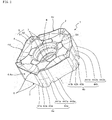
- the insert 1 of the present embodiment generally includes a top surface 2, a lower surface 3, a side surface 4 connected to the top surface 2 and the lower surface 3, and a cutting edge 5 located in an intersection region of the top surface 2 and the side surface 4.
- a second flat cutting edge 5c included in the cutting edge 5 is located from a first intersection region L1 to a second intersection region L2 in the intersection region, and has a lowermost portion V in the first intersection region L1 in a side view.
- the insert 1 has the above configuration. Therefore, even when the insert 1 is attached to a holder 21 shown in Fig. 4 by setting the axial rake angle thereof to a negative value with respect to the holder 21, as shown in Fig. 6 , the second flat cutting edge 5c can be positioned substantially parallel to the machined surface 101 of the workpiece 100 over the entire length of the second flat cutting edge, thus allowing the machined surface 101 of the workpiece 100 to be cut with high smoothness.
- a first inclined cutting edge 52a located in the second intersection region L2 but also a curved cutting edge 51b (cutting edge portion) located in the first intersection region L1 is usable as a part of the second flat cutting edge 5c.
- the desired length of the second flat cutting edge 5c can be ensured while relatively shortening the first inclined cutting edge 52c. Consequently, the entire length of the second major cutting edge 5d can be further increased, thereby ensuring a large depth of cut.
- the components of the insert 1 are described in detail below.
- the insert 1 includes a substantially polygonal plate shaped body.
- the body includes the top surface 2, a part of which functions as a rake surface 9; the lower surface 3, a part of which functions as a seating surface; and the side surface 4 that functions as a flank surface.
- the shape of the body may have a certain shape usually employed by those skilled in the art, such as triangle, quadrangle, pentagon, hexagon, and octagon in a top view.
- the present embodiment employs a substantially pentagonal shape having five long sides.
- the body is preferably made of a cemented carbide substrate, a cermet substrate, or the like.
- a PVD film or CVD film formed by PVD method or CVD method, or a composite film of these is preferably formed on the surface of these substrates.
- a structure having the PVD film formed on the surface of the cemented carbide substrate is suitable in the machining necessitating chipping resistance, such as when cutting steel, stainless steel, or ductile cast iron.
- a structure having the CVD film formed on the surface of the cemented carbide substrate is suitable in the machining necessitating wear resistance, such as highspeed cutting of gray cast iron.
- a structure having the PVD film formed on the surface of the cermet substrate is suitable in finishing.
- the insert 1 is a so-called negative type insert in which the side surface 4 is perpendicularly connected to the upper surface 2 and the lower surface 3, and both the upper surface 2 and the lower surface 3 can be used as the rake surface. Therefore, in the insert 1, five corners per surface, or ten corners on both the upper and lower surfaces can be used for cutting process.
- the cutting edge 5 is also formed in the intersection region of the lower surface 3 and the side surface 4. Therefore, when cutting is carried out using the cutting edge 5 close to the lower surface 3, the lower surface 3 is usable as a rake surface, and the upper surface 2 is usable as a seating surface.
- the cutting edge 5 close to the lower surface 3 has a shape obtained by reversing the cutting edge 5 close to the upper surface 2. That is, these cutting edges 5 of the upper and lower surfaces are rotationally symmetric about a line perpendicular to the paper surface of Fig. 3(a) .
- the side surface 4 is continuous with the upper surface 2 and the lower surface 3. As shown in Fig. 2 , the side surface 4 includes a first side surface 4a, a second side surface 4b, a third side surface 4c, a fourth side surface 4d, and a fifth side surface 4e which are respectively connected to individual sides of the upper surface that is substantially a pentagon. These side surfaces 4a to 4e have similar configurations. Hence, the following description is given of the first side surface 4a and the second side surface 4b located adjacent to each other.
- the first side surface 4a sequentially includes a first chamfered side surface 41a with a curved shape, a first corner side surface 42a with a planar shape, a first intermediate side surface 43a with a curved shape, and a first major side surface 44a with a planar shape.
- the second side surface 4b sequentially includes a second chamfered side surface 41b with a curved shape, a second corner side surface 42b with a planar shape, a second intermediate side surface 43b with a curved shape, and a second major side surface 44b with a planar shape.
- intersection region of the side surface 4 and the upper surface 2 An intersection region of the first side surface 4a and the upper surface 2, and an intersection region of the second side surface 4b and the upper surface 2 have similar configurations.
- the intersection region of the second side surface 4b and the upper surface 2 in these intersection regions is described below.
- this intersection region includes a first intersection region L1 of the second chamfered side surface 41b and the upper surface 2, a second intersection region L2 of the second corner side surface 42b and the upper surface 2, a third intersection region L3 of the second intermediate side surface 43b and the upper surface 2, and a fourth intersection region L4 of the second major side surface 44b and the upper surface 2.
- the cutting edges 5 located in these intersection regions respectively correspond to the side surfaces (41a, 41b to 44a, and 44b), and have five combinations to the substantially pentagon, which are respectively made up of a chamfered cutting edge 51, a corner cutting edge 52, an intermediate cutting edge 53, and a primary cutting edge 54.
- These cutting edges 51 to 54 produce a configuration in which the flat cutting edge for improving the smoothness of the machined surface 101 of the workpiece 100, and the major cutting edge playing a role in generating chips during cutting action are alternately located.
- the flat cutting edge and the major cutting edge are alternately located in the following order: the first flat cutting edge 5a, the first major cutting edge 5b, the second flat cutting edge 5c, and the second major cutting edge 5d.
- the first flat cutting edge 5a and the first major cutting edge 5b are sequentially located in the intersection region of the first side surface 4a and the upper surface 2.
- the second flat cutting edge 5c and the second major cutting edge 5d are sequentially located in the intersection region of the second side surface 4b and the upper surface 2.
- These flat cutting edges 5a and 5c have similar configurations, and these major cutting edges 5b and 5d have similar configurations.
- the individual cutting edges 51 to 54 located in the intersection region of the second side surface 4b and the upper surface are mainly sequentially described.
- the chamfered cutting edge 51 is located in the first intersection region L1 correspondingly to the second chamfered side surface 41b, as shown in Fig. 3 .
- the chamfered cutting edge 51 is an outward convex curve in a top view, and includes an auxiliary primary cutting edge 51a and a curved cutting edge 51b, as shown in Fig. 1 .
- the auxiliary primary cutting edge 51a is located between the first major cutting edge 5b and the curved cutting edge 51b (second flat cutting edge 5c). As shown in Fig. 3 , the auxiliary primary cutting edge 51a is inclined downward from the adjacent first major cutting edge 5b to the curved cutting edge 51b (second flat cutting edge 5c) with respect to a reference plane S perpendicular to a central axis S1 of the insert 1 in a side view. More specifically, the auxiliary primary cutting edge 51a is continuously inclined downward with respect to the reference plane S, from the first major cutting edge 5b to the curved cutting edge 51b (second flat cutting edge 5c) in the side view.
- the first major cutting edge 5b and the second flat cutting edge 5c interpose therebetween the chamfered cutting edge 51 inclined downward with respect to the reference plane S. This reduces the probability that chips generated during cutting of the workpiece by the first major cutting edge 5b come into contact with the curved cutting edge 51b (second flat cutting edge 5c), thus making it possible to reduce damage to the curved cutting edge 51b (second flat cutting edge 5c).
- the auxiliary primary cutting edge 51a may be used for generating chips together with the adjacent primary cutting edge 54 as needed. This ensures a large depth of cut.
- the auxiliary primary cutting edge 51a includes a portion whose downward inclination angle with respect to the reference plane S is increased from the first major cutting edge 5b to the curved cutting edge 51b (second flat cutting edge 5c) in the side view.
- the auxiliary primary cutting edge 51a may be configured so that the inclination angle thereof is gradually increased over the entire length thereof.
- the curved cutting edge 51b has a the downward convex curve with respect to the reference plane S in the side view, and serves a function as a part of the second flat cutting edge 5c.
- An intermediate region of the curved cutting edge 51b constitutes a lowermost portion V of the cutting edge 5.
- the term "lowermost portion” denotes a portion, such as a point or region, located lowermost in the cutting edge 5 with respect to the reference plane S.
- a curve formed by the curved cutting edge 51b is a spline curve, as described in the following. Accordingly, the lowermost portion V in the present embodiment is not a region having a predetermined length, but a point located lowermost (lowermost point).
- the curved cutting edge 51b has the spline curve as described above, and is positioned substantially parallel to the machined surface 101 of the workpiece 100 when the insert 1 is attached to the holder 21. This allows the machined surface 101 of the workpiece 100 to be cut with high smoothness.
- the insert 1 of the present embodiment not only the first inclined cutting edge 52a described later which is located at the second intersection region L2, but also the curved cutting edge 51b located in the first intersection region L1 is usable as a part of the second flat cutting edge 5c. This ensures the desired length of the second flat cutting edge 5c while relatively shortening the first inclined cutting edge 52a. Consequently, the entire length of the second major cutting edge 5d can be further increased, thereby ensuring a large depth of cut.
- the corner cutting edge 52 is located in the second intersection region L2 correspondingly to the second corner side surface 42b. As shown in Fig. 1 , the corner cutting edge 52 is a straight line in a top view, and includes a first inclined cutting edge 52a and a second inclined cutting edge 52b.
- the first inclined cutting edge 52a is inclined upward in a direction away from the curved cutting edge 51b with respect to the reference plane S in a side view, and serves a function as a part of the second flat cutting edge 5c.
- the second flat cutting edge 5c includes the curved cutting edge 51b and the first inclined cutting edge 52a, and its one end portion "a" is located at the end of the curved cutting edge 51b close to the auxiliary primary cutting edge 51a, and its the other end portion "b” is located at the end of the first inclined cutting edge 52a close to the second inclined cutting edge 52b.
- the second flat cutting edge 5c is a downward convex curve on the whole with respect to the reference plane S in the side view.
- the second flat cutting edge 5c is located from the first intersection region L1 to the second intersection region L2, and includes the lowermost portion V in the first intersection region L1 in the side view.
- the first inclined cutting edge 52a that functions as the second flat cutting edge 5c is inclined in the side view. Therefore, the width of the second corner side surface 42b that is the corresponding side surface in a top view can be relatively decreased. This ensures that the entire length of the second major cutting edge 5d is further increased, thereby ensuring a large depth of cut.
- the second inclined cutting edge 52b is also inclined upward in a direction away from the first inclined cutting edge 52a with respect to the reference plane S in a side view, and the inclination angle thereof is decreased toward the intermediate cutting edge 53.
- the intermediate cutting edge 53 is located in the third intersection region L3 correspondingly to the second intermediate side surface 43b, and connects the corner cutting edge 52 and the primary cutting edge 54.
- the intermediate cutting edge 53 is an outward convex curve in a side view, as shown in Fig. 1 , and is an upward convex curve having an uppermost portion P in a side view, as shown in Fig. 3 .
- the term "uppermost portion” denotes a portion, such as a point or region, located uppermost in the cutting edge 5 with respect to the reference plane S.
- the second inclined cutting edge 52b and the intermediate cutting edge 53 are located to connect the second flat cutting edge 5c and the second major cutting edge 5d, and are relatively gentle curves in a top view. These cutting edges serve a function to reduce fracture of the first cutting edge 54 described later.
- the primary cutting edge 54 is located in the fourth intersection region L4 correspondingly to the second major side surface 44b, and includes a first cutting edge 54a, a second cutting edge 54b, and a third cutting edge 54c. As shown in Fig. 1 , the first cutting edge 54a has a linear shape, the second cutting edge 54b has a curved shape, and the third cutting edge 54c has a linear shape in a top view.
- the primary cutting edge 54 functions as a primary part of the first major cutting edge 5b and the second major cutting edge 5d, and is inclined downward with respect to the reference plane S in a side view.
- the first major cutting edge 5b is described below.
- the first major cutting edge 5b is inclined downward toward the second corner side surface 42b with respect to the reference plane S in the side view.
- the first major cutting edge 5b is continuously inclined downward toward the second corner side surface 42b with respect to the reference plane S in the side view. This reduces cutting resistance.
- the first major cutting edge is not limited to the continuously inclined configuration, but may include, for example, a flat portion in the middle of the inclination thereof as needed.
- the first cutting edge 54a has a larger peripheral cutting edge angle than the third cutting edge 54c, and plays a role in assisting the cutting by the third cutting edge 54c, such as mitigating the cutting resistance of the third cutting edge 54c, or reducing the damage to the third cutting edge 54c.
- the peripheral cutting edge angle is described later.
- the second cutting edge 54b is an outward convex curve in a top view, and plays a role in connecting the linear first cutting edge 54a and the linear third cutting edge 54c. This avoids a vast difference between the thickness of chips generated by the third cutting edge 54c and the thickness of chips generated by the first cutting edge 54a, thus permitting the chip shape control.
- the load exerted on the boundary of the first cutting edge 54a and the third cutting edge 54c during cutting can be dispersed by connecting the first cutting edge 54a and the third cutting edge 54c through the second cutting edge 54b. This reduces fracture occurred at the boundary and also permits smooth escape of the chips.
- the third cutting edge 54c is made longer than the first cutting edge 54a and the second cutting edge 54b, and plays a major role in generating chips during cutting action.
- peripheral cutting edge angle denotes an inclination angle of the cutting edge 5 with respect to a rotation axis S2 of the holder 21 when the insert 1 is attached to the holder 21.
- an angle ⁇ formed by a line parallel to the rotation axis S2 of the holder 21 and the third cutting edge 54c is a peripheral cutting edge angle of the third cutting edge 54c.
- an angle ⁇ 2 formed by the line L and the first cutting edge 54a is a peripheral cutting edge angle of the first cutting edge 54a.
- the peripheral cutting edge angle of the first cutting edge 54a is preferably set to be larger than the peripheral cutting edge angle of the third cutting edge 54c.
- the peripheral cutting edge angle of the first cutting edge 54a is set to be 1.2 times, preferably not less than 1.5 times the peripheral cutting edge angle of the third cutting edge 54c.
- the peripheral cutting edge angle of the third cutting edge 54c is set to, for example, approximately 0-60°, and the peripheral cutting edge angle of the first cutting edge 54a is set to an angle larger than that, for example, approximately 60-80°.
- the first cutting edge 54a merely needs to be located between the third cutting edge 54c and the second flat cutting edge 5c, and a plurality of auxiliary cutting edges may be disposed between the two.
- the ratio of the length of the third cutting edge 54c and the length of the first cutting edge 54a is approximately 2:1 to 10:1, preferably 2:1 to 6:1.
- the cutting edges 51 to 54 located in the intersection region of the second side surface 4b and the upper surface 2 have been exemplified above, these cutting edges 51 to 54 are formed in not only the intersection region of the second side surface 4b and the upper surface 2, but also the intersection region of the first side surface 4a and the upper surface 2, as described above. That is, the first flat cutting edge 5a includes the curved cutting edge 51b that is a part of the chamfered cutting edge 51, and the first inclined cutting edge 52a that is a part of the corner cutting edge 52.
- the first major cutting edge 5b is made up mainly of the primary cutting edge 54.
- the second inclined cutting edge 52b and the intermediate cutting edge 53 that are part of the corner cutting edge 52 located close to one end of the primary cutting edge 54, and the auxiliary primary cutting edge 51a that is part of the chamfered cutting edge 51 located close to the other end of the primary cutting edge 54 are used complementarily.
- the first flat cutting edge 5a, the first major cutting edge 5b, the second flat cutting edge 5c, and the second major cutting edge 5d are continuously alternately formed by these cutting edges 51 to 54 respectively located in the intersection regions.
- a first cutting process is executed by the first flat cutting edge 5a and the first major cutting edge 5b.
- a second cutting process is executed by the second flat cutting edge 5c and the second major cutting edge 5d.
- the insert 1 of the present embodiment is capable of performing cutting up to a fifth cutting process on either the upper surface 2 or the lower surface 3.
- a through hole 6 extending through the body from the upper surface 2 to the lower surface 3 is formed at a middle part of the upper surface 2.
- the through hole 6 plays a role in passing an attachment screw 25 used for attaching the insert 1 to the holder 21.
- a step part inside the through hole 6 is a contact part 7 to be engaged with the head of the attachment screw 25.
- the contact part 7 is formed at upper and lower parts so that the insert 1 can be reversely attached thereto.
- Lands 8 are respectively formed along the cutting edges 5 on the upper surface 2. These lands 8 play a role in improving fracture resistance of the cutting edges 5, and are narrow-width flat surfaces. The widths of these lands 8 are suitably set from the viewpoint of the strength of the corresponding cutting edges 51 to 54. The widths of the lands 8 are usually set to a substantially constant value. In another embodiment, the lands 8 may not be disposed from the viewpoint of reducing cutting resistance.
- the rake surface 9 (inclined surface) is formed correspondingly to the primary cutting edge 54 on the inward side of the land 8.
- the rake surface 9 is formed along the entire cutting edge 5, and includes a first rake surface 91 corresponding to the third cutting edge 54c and the first cutting edge 54a, and a second rake surface 92 connected to the first rake surface 91.
- the first rake surface 91 and the second rake surface 92 may have a planar shape or curved surface shape.
- the planar first rake surface 91 and the planar second rake surface 92 may be connected to each other through a curved surface shaped intermediate rake surface.
- the cutting tool 20 (rotary cutting tool) according to the present embodiment has a plurality of inserts 1 attached to the holder 21.
- the holder 21 has a plurality of circumferentially spaced insert pockets 22 at the peripheral front end thereof.
- the insert pockets 22 are portions obtained by cutting off the holder 21 into a substantially V-shape in a top view.
- the inserts 1 are respectively attached to a plurality of insert attachment surfaces 23 formed by the cutting off.
- Each of the inserts 1 is attached to the holder 21 with the upper surface 2 oriented forwardly in the direction of rotation of the holder 21 indicated by arrow A, and with the primary cutting edge 54 protruded outward from the outer periphery of the holder 21.
- the inserts 1 are attached along the same circumference of the holder 21.
- the attachment thereof is carried out by inserting the attachment screw 25 into the through hole 6 of each insert 1, and then screwing the attachment screw 25 into a female screw formed in the insert attachment surface 23 of the holder 21.
- the rotation axis S2 of the holder 21 is positioned substantially perpendicular to a surface 101 of the workpiece 100 shown in Fig. 5 .
- the third cutting edge 54c is inclined at an angle of approximately 45° with respect to the workpiece 100.
- the second flat cutting edge 5c and the surface 101 of the workpiece 100 are positioned parallel to each other by setting a so-called axial rake angle to be a negative value, for example, -6°.
- the insert 1 is attached to the holder 21 so that the insert 1 has a negative axial rake angle with respect to the rotation axis S2 of the holder 21.
- the second flat cutting edge 5c is perpendicular to the rotation axis S2 of the holder 21.
- the axial rake angle is determined by an angle formed by the reference plane S in the insert 1 shown in Fig. 3(a) , and the rotation axis S2 of the holder 21 (refer to Figs. 4 and 5 ) .
- the second flat cutting edge 5c and the surface 101 of the workpiece 100 are not perfectly parallel to each other.
- the second flat cutting edge 5c may be set at a gentle arcuate position with respect to the surface 101 of the workpiece 100. In this case, it is preferable to set to be arc of approximately R50 to R500.
- a radial rake angle of the insert 1 with respect to the holder 21 is preferably set at a value of approximately -6° or less from the viewpoint of reducing the probability that an edge ridge portion of the lower surface of the insert 1 (when the upper surface thereof is used for cutting) interferes with a machined wall surface of the workpiece.
- the radial rake angle is preferably set at a value of approximately 20° or more from the viewpoint of reducing deterioration of the edge strength by relatively decreasing an actual clearance angle.
- the radial rake angle is more preferably set at -6 to -8° in order to achieve well-balanced compatibility of the above-mentioned two operation advantages.
- the second flat cutting edge 5c and the second major cutting edge 5d cut the workpiece 100 by rotating the holder 21 in the direction of arrow A with reference to the rotation axis S2.
- the method of manufacturing the machined product according to the present embodiment includes the step of rotating the cutting tool 20; the step of bringing the cutting edges 5 of the rotating cutting tool 20 into contact with the workpiece 100; and the step of separating the cutting tool 20 from the workpiece 100.
- the workpiece 100 is fixed to a bed or the like of a milling machine (not shown), and an appropriate depth of cut is set by moving the holder 21 in a direction of arrow B, as shown in Fig. 7(a) .
- the holder 21 is moved in a direction of arrow C while being rotated in the direction of arrow A around the rotation axis S2. This brings the primary cutting edge 54 into contact with the workpiece 100 located ahead in a feed direction, thereby cutting the workpiece 100 according to the depth of cut.
- the plurality of inserts 1 sequentially enter a cutting region and perform cutting with the rotation. Therefore, an arcuate line (cutting trace) remains on the surface 101 of the workpiece 100.
- the arcuate line (cutting trace) is cut by the second flat cutting edge 5c, thus smoothing the surface 101.
- it is set so that a part (lower part) of the entire length of the third cutting edge 54c close to the first cutting edge 54a cuts into the workpiece 100 by a predetermined depth of cut K.
- the above cutting process may be repeated by bringing the cutting edges 5 into contact with the same portion or different portions of the workpiece 100 while retaining the rotation of the cutting tool 20. Accordingly, the operation that the individual inserts 1 contact and cut the workpiece 100 and then separate from the workpiece 100 is repeated sequentially.
- the cutting edge portion in use is worn, the cutting can be continued with an unused cutting edge portion by rotating the insert 1 around the center axis S1 of the insert 1, or turning upside down.
- the inserts 1 according to the foregoing embodiment has the configuration that both the upper surface 2 and the lower surface 3 are usable as the rake surface.
- the negative type cutting insert may be configured so that no cutting edge 5 is formed close to the lower surface 3. Even in this case, five corners are usable for cutting.
- a predetermined inclination may be disposed between the other end portion "b" of the second flat cutting edge 5c and the machined surface 101 of the workpiece 100 so that the other end portion "b” protrudes outward from the front end of the holder 21 than the one end portion "a.”
- the second flat cutting edge 5c is configured so that a straight line passing through its both end portions "a" and "b" is perpendicular to the rotation axis S2 of the holder 21, and is also configured to be a convex curve toward the front end of the holder 21.
- the radius of curvature of the curve may be constant over the entire length of the second flat cutting edge 5c.
- the radius of curvature may be substantially constant. That is, even when there is an unavoidable error caused by manufacturing errors, attachment errors or the like of the inserts 1 and the holder 21, it is regarded as being "constant.”
- the cutting is carried out by feeding the rotating cutting tool 20.
- the workpiece 100 may be fed and traveled while holding the rotating cutting tool 20 at a predetermined position.
- the cutting may be carried out by bringing the unrotated cutting tool 20 into contact with the rotating workpiece 100.
- processing machines include face milling cutters, end mills, milling machines, and drills.
- the inserts of the present invention can be used by attaching them to holders or chucks of these different types of processing machines.
Landscapes
- Engineering & Computer Science (AREA)
- Mechanical Engineering (AREA)
- Milling Processes (AREA)
- Cutting Tools, Boring Holders, And Turrets (AREA)
Abstract
Description
- The present invention relates to a cutting insert, a cutting tool, and a method of manufacturing a machined product using the same.
- Japanese Unexamined Patent Publication No.
9-509104 sub cutting edge 5b parallel to a support surface 3, between amajor cutting edge 4a and asub cutting edge 5a, as shown in Fig. 14 in the publication. - However, when the cutting insert 1b is attached to a tool 14 with a negative axial rake angle, the secondary
sub cutting edge 5b protrudes toward the front end of the tool 14 than thesub cutting edge 5a. There is therefore a risk of deterioration of the smoothness of a machined surface (bottom surface) of a workpiece. - An object of the present invention is to provide a cutting insert and a cutting tool, which allow the machined surface of the workpiece to be cut with high smoothness, and a method of manufacturing a machined product using the cutting tool.
- A cutting insert of the present invention includes an upper surface; a lower surface; a side surface which is connected to the upper surface and the lower surface and has a first side surface and a second side surface in order; and a cutting edge includes a first flat cutting edge and a first major cutting edge in order in an intersection region of the first side surface and the upper surface, and has a second flat cutting edge and a second major cutting edge in order in an intersection region of the second side surface and the upper surface. The first side surface includes a first chamfered side surface with a curved shape, a first corner side surface with a planar shape, and a first major side surface in order. The second side surface includes a second chamfered side surface with a curved shape, a second corner side surface with a planar shape, and a second major side surface in order. The intersection region of the second side surface and the upper surface includes a first intersection region of the second chamfered side surface and the upper surface, and a second intersection region of the second corner side surface and the upper surface. The second flat cutting edge is located from the first intersection region to the second intersection region, and has a lowermost portion in the first intersection region in a side view.
- A cutting tool according to an embodiment of the present invention includes the cutting insert and a holder configured to attach the cutting insert thereto.
- A method of manufacturing a machined product according to an embodiment of the present invention includes rotating the cutting tool; bringing the cutting edge of the rotating cutting tool into contact with a workpiece; and separating the cutting tool from the workpiece.
- In the cutting insert according to the foregoing embodiment, the second flat cutting edge is located from the first intersection region to the second intersection region, and has the lowermost portion in the first intersection region in the side view. Therefore, even when the cutting insert is attached to the holder by setting the axial rake angle of the cutting insert to a negative value, the second flat cutting edge can be positioned substantially parallel to the machined surface of the workpiece over the entire length of the second flat cutting edge, thus allowing the machined surface of the workpiece to be cut with high smoothness. Additionally, not only the cutting edge portion (the first inclined cutting edge) located in the second intersection region, but also the cutting edge portion (the curved cutting edge) located in the first intersection region is usable as a part of the second flat cutting edge. This ensures the desired length of the second flat cutting edge while relatively shortening the first inclined cutting edge. Consequently, the entire length of the second major cutting edge can be further elongated, thus ensuring a large depth of cut.
-
-
Fig. 1 is a top view showing a cutting insert according to an embodiment of the present invention; -
Fig. 2 is a perspective view of the cutting insert shown inFig. 1 ; -
Fig. 3(a) is a side view of the cutting insert shown inFig. 1 taken in the direction of arrow X;Fig. 3(b) is a partially enlarged view thereof; -
Fig. 4 is a side view showing a cutting tool according to an embodiment of the present invention; -
Fig. 5 is a partially enlarged view of the cutting tool shown inFig. 4 ; -
Fig. 6 is another partially enlarged view of the cutting tool shown inFig. 4 ; and -
Fig. 7 is a process drawing showing a method of manufacturing a machined product according to an embodiment of the present invention. - An embodiment of the cutting insert (hereinafter referred to as an "insert" in some cases) according to the present invention is described in detail below with reference to
Figs. 1 to 3 . - As shown in
Figs. 1 and2 , theinsert 1 of the present embodiment generally includes atop surface 2, a lower surface 3, aside surface 4 connected to thetop surface 2 and the lower surface 3, and acutting edge 5 located in an intersection region of thetop surface 2 and theside surface 4. As shown inFig. 3(b) , a secondflat cutting edge 5c included in thecutting edge 5 is located from a first intersection region L1 to a second intersection region L2 in the intersection region, and has a lowermost portion V in the first intersection region L1 in a side view. - The
insert 1 has the above configuration. Therefore, even when theinsert 1 is attached to aholder 21 shown inFig. 4 by setting the axial rake angle thereof to a negative value with respect to theholder 21, as shown inFig. 6 , the secondflat cutting edge 5c can be positioned substantially parallel to themachined surface 101 of theworkpiece 100 over the entire length of the second flat cutting edge, thus allowing themachined surface 101 of theworkpiece 100 to be cut with high smoothness. InFig. 3(b) , not only a firstinclined cutting edge 52a located in the second intersection region L2, but also acurved cutting edge 51b (cutting edge portion) located in the first intersection region L1 is usable as a part of the secondflat cutting edge 5c. Therefore, the desired length of the secondflat cutting edge 5c can be ensured while relatively shortening the first inclined cutting edge 52c. Consequently, the entire length of the secondmajor cutting edge 5d can be further increased, thereby ensuring a large depth of cut. Hereinafter, the components of theinsert 1 are described in detail below. - The
insert 1 includes a substantially polygonal plate shaped body. The body includes thetop surface 2, a part of which functions as a rake surface 9; the lower surface 3, a part of which functions as a seating surface; and theside surface 4 that functions as a flank surface. No particular limitation is imposed on the shape of the body. That is, the body may have a certain shape usually employed by those skilled in the art, such as triangle, quadrangle, pentagon, hexagon, and octagon in a top view. The present embodiment employs a substantially pentagonal shape having five long sides. - The body is preferably made of a cemented carbide substrate, a cermet substrate, or the like. A PVD film or CVD film formed by PVD method or CVD method, or a composite film of these is preferably formed on the surface of these substrates. In particular, a structure having the PVD film formed on the surface of the cemented carbide substrate is suitable in the machining necessitating chipping resistance, such as when cutting steel, stainless steel, or ductile cast iron. A structure having the CVD film formed on the surface of the cemented carbide substrate is suitable in the machining necessitating wear resistance, such as highspeed cutting of gray cast iron. A structure having the PVD film formed on the surface of the cermet substrate is suitable in finishing.
- The
insert 1 is a so-called negative type insert in which theside surface 4 is perpendicularly connected to theupper surface 2 and the lower surface 3, and both theupper surface 2 and the lower surface 3 can be used as the rake surface. Therefore, in theinsert 1, five corners per surface, or ten corners on both the upper and lower surfaces can be used for cutting process. - To be specific, the
cutting edge 5 is also formed in the intersection region of the lower surface 3 and theside surface 4. Therefore, when cutting is carried out using thecutting edge 5 close to the lower surface 3, the lower surface 3 is usable as a rake surface, and theupper surface 2 is usable as a seating surface. In the present embodiment, thecutting edge 5 close to the lower surface 3 has a shape obtained by reversing thecutting edge 5 close to theupper surface 2. That is, thesecutting edges 5 of the upper and lower surfaces are rotationally symmetric about a line perpendicular to the paper surface ofFig. 3(a) . - The
side surface 4 is continuous with theupper surface 2 and the lower surface 3. As shown inFig. 2 , theside surface 4 includes afirst side surface 4a, asecond side surface 4b, athird side surface 4c, afourth side surface 4d, and a fifth side surface 4e which are respectively connected to individual sides of the upper surface that is substantially a pentagon. Theseside surfaces 4a to 4e have similar configurations. Hence, the following description is given of thefirst side surface 4a and thesecond side surface 4b located adjacent to each other. - The
first side surface 4a sequentially includes a first chamferedside surface 41a with a curved shape, a firstcorner side surface 42a with a planar shape, a firstintermediate side surface 43a with a curved shape, and a first major side surface 44a with a planar shape. Similarly, thesecond side surface 4b sequentially includes a second chamferedside surface 41b with a curved shape, a secondcorner side surface 42b with a planar shape, a secondintermediate side surface 43b with a curved shape, and a secondmajor side surface 44b with a planar shape. - The
cutting edge 5 described later is located in the intersection region of theside surface 4 and theupper surface 2. An intersection region of thefirst side surface 4a and theupper surface 2, and an intersection region of thesecond side surface 4b and theupper surface 2 have similar configurations. The intersection region of thesecond side surface 4b and theupper surface 2 in these intersection regions is described below. As shown inFig. 3(b) , this intersection region includes a first intersection region L1 of the secondchamfered side surface 41b and theupper surface 2, a second intersection region L2 of the secondcorner side surface 42b and theupper surface 2, a third intersection region L3 of the secondintermediate side surface 43b and theupper surface 2, and a fourth intersection region L4 of the secondmajor side surface 44b and theupper surface 2. - As shown in
Figs. 1 and2 , thecutting edges 5 located in these intersection regions respectively correspond to the side surfaces (41a, 41b to 44a, and 44b), and have five combinations to the substantially pentagon, which are respectively made up of a chamferedcutting edge 51, acorner cutting edge 52, an intermediatecutting edge 53, and aprimary cutting edge 54. These cutting edges 51 to 54 produce a configuration in which the flat cutting edge for improving the smoothness of the machinedsurface 101 of theworkpiece 100, and the major cutting edge playing a role in generating chips during cutting action are alternately located. - To be specific, as shown in
Fig. 1 , the flat cutting edge and the major cutting edge are alternately located in the following order: the firstflat cutting edge 5a, the firstmajor cutting edge 5b, the secondflat cutting edge 5c, and the secondmajor cutting edge 5d. The firstflat cutting edge 5a and the firstmajor cutting edge 5b are sequentially located in the intersection region of thefirst side surface 4a and theupper surface 2. The secondflat cutting edge 5c and the secondmajor cutting edge 5d are sequentially located in the intersection region of thesecond side surface 4b and theupper surface 2. Theseflat cutting edges major cutting edges individual cutting edges 51 to 54 located in the intersection region of thesecond side surface 4b and the upper surface are mainly sequentially described. - The chamfered
cutting edge 51 is located in the first intersection region L1 correspondingly to the secondchamfered side surface 41b, as shown inFig. 3 . The chamferedcutting edge 51 is an outward convex curve in a top view, and includes an auxiliaryprimary cutting edge 51a and acurved cutting edge 51b, as shown inFig. 1 . - The auxiliary
primary cutting edge 51a is located between the firstmajor cutting edge 5b and thecurved cutting edge 51b (secondflat cutting edge 5c). As shown inFig. 3 , the auxiliaryprimary cutting edge 51a is inclined downward from the adjacent firstmajor cutting edge 5b to thecurved cutting edge 51b (secondflat cutting edge 5c) with respect to a reference plane S perpendicular to a central axis S1 of theinsert 1 in a side view. More specifically, the auxiliaryprimary cutting edge 51a is continuously inclined downward with respect to the reference plane S, from the firstmajor cutting edge 5b to thecurved cutting edge 51b (secondflat cutting edge 5c) in the side view. The firstmajor cutting edge 5b and the secondflat cutting edge 5c interpose therebetween the chamferedcutting edge 51 inclined downward with respect to the reference plane S. This reduces the probability that chips generated during cutting of the workpiece by the firstmajor cutting edge 5b come into contact with thecurved cutting edge 51b (secondflat cutting edge 5c), thus making it possible to reduce damage to thecurved cutting edge 51b (secondflat cutting edge 5c). - The auxiliary
primary cutting edge 51a may be used for generating chips together with the adjacentprimary cutting edge 54 as needed. This ensures a large depth of cut. The auxiliaryprimary cutting edge 51a includes a portion whose downward inclination angle with respect to the reference plane S is increased from the firstmajor cutting edge 5b to thecurved cutting edge 51b (secondflat cutting edge 5c) in the side view. Alternatively, the auxiliaryprimary cutting edge 51a may be configured so that the inclination angle thereof is gradually increased over the entire length thereof. - The
curved cutting edge 51b has a the downward convex curve with respect to the reference plane S in the side view, and serves a function as a part of the secondflat cutting edge 5c. An intermediate region of thecurved cutting edge 51b constitutes a lowermost portion V of thecutting edge 5. In the present specification, the term "lowermost portion" denotes a portion, such as a point or region, located lowermost in thecutting edge 5 with respect to the reference plane S. In the present embodiment, a curve formed by thecurved cutting edge 51b is a spline curve, as described in the following. Accordingly, the lowermost portion V in the present embodiment is not a region having a predetermined length, but a point located lowermost (lowermost point). - The
curved cutting edge 51b has the spline curve as described above, and is positioned substantially parallel to the machinedsurface 101 of theworkpiece 100 when theinsert 1 is attached to theholder 21. This allows the machinedsurface 101 of theworkpiece 100 to be cut with high smoothness. In theinsert 1 of the present embodiment, not only the firstinclined cutting edge 52a described later which is located at the second intersection region L2, but also thecurved cutting edge 51b located in the first intersection region L1 is usable as a part of the secondflat cutting edge 5c. This ensures the desired length of the secondflat cutting edge 5c while relatively shortening the firstinclined cutting edge 52a. Consequently, the entire length of the secondmajor cutting edge 5d can be further increased, thereby ensuring a large depth of cut. - The
corner cutting edge 52 is located in the second intersection region L2 correspondingly to the secondcorner side surface 42b. As shown inFig. 1 , thecorner cutting edge 52 is a straight line in a top view, and includes a firstinclined cutting edge 52a and a secondinclined cutting edge 52b. - As shown in
Fig. 3(b) , the firstinclined cutting edge 52a is inclined upward in a direction away from thecurved cutting edge 51b with respect to the reference plane S in a side view, and serves a function as a part of the secondflat cutting edge 5c. Thus, in theinsert 1 of the present embodiment, the secondflat cutting edge 5c includes thecurved cutting edge 51b and the firstinclined cutting edge 52a, and its one end portion "a" is located at the end of thecurved cutting edge 51b close to the auxiliaryprimary cutting edge 51a, and its the other end portion "b" is located at the end of the firstinclined cutting edge 52a close to the secondinclined cutting edge 52b. Hence, the secondflat cutting edge 5c is a downward convex curve on the whole with respect to the reference plane S in the side view. The secondflat cutting edge 5c is located from the first intersection region L1 to the second intersection region L2, and includes the lowermost portion V in the first intersection region L1 in the side view. Additionally, the firstinclined cutting edge 52a that functions as the secondflat cutting edge 5c is inclined in the side view. Therefore, the width of the secondcorner side surface 42b that is the corresponding side surface in a top view can be relatively decreased. This ensures that the entire length of the secondmajor cutting edge 5d is further increased, thereby ensuring a large depth of cut. - The second
inclined cutting edge 52b is also inclined upward in a direction away from the firstinclined cutting edge 52a with respect to the reference plane S in a side view, and the inclination angle thereof is decreased toward theintermediate cutting edge 53. - The
intermediate cutting edge 53 is located in the third intersection region L3 correspondingly to the secondintermediate side surface 43b, and connects thecorner cutting edge 52 and theprimary cutting edge 54. Theintermediate cutting edge 53 is an outward convex curve in a side view, as shown inFig. 1 , and is an upward convex curve having an uppermost portion P in a side view, as shown inFig. 3 . In the present specification, the term "uppermost portion" denotes a portion, such as a point or region, located uppermost in thecutting edge 5 with respect to the reference plane S. - Hereat, the second
inclined cutting edge 52b and theintermediate cutting edge 53 are located to connect the secondflat cutting edge 5c and the secondmajor cutting edge 5d, and are relatively gentle curves in a top view. These cutting edges serve a function to reduce fracture of thefirst cutting edge 54 described later. - The
primary cutting edge 54 is located in the fourth intersection region L4 correspondingly to the secondmajor side surface 44b, and includes afirst cutting edge 54a, asecond cutting edge 54b, and athird cutting edge 54c. As shown inFig. 1 , thefirst cutting edge 54a has a linear shape, thesecond cutting edge 54b has a curved shape, and thethird cutting edge 54c has a linear shape in a top view. - The
primary cutting edge 54 functions as a primary part of the firstmajor cutting edge 5b and the secondmajor cutting edge 5d, and is inclined downward with respect to the reference plane S in a side view. For example, the firstmajor cutting edge 5b is described below. As shown inFig. 3 , the firstmajor cutting edge 5b is inclined downward toward the secondcorner side surface 42b with respect to the reference plane S in the side view. More specifically, the firstmajor cutting edge 5b is continuously inclined downward toward the secondcorner side surface 42b with respect to the reference plane S in the side view. This reduces cutting resistance. The first major cutting edge is not limited to the continuously inclined configuration, but may include, for example, a flat portion in the middle of the inclination thereof as needed. - The
first cutting edge 54a has a larger peripheral cutting edge angle than thethird cutting edge 54c, and plays a role in assisting the cutting by thethird cutting edge 54c, such as mitigating the cutting resistance of thethird cutting edge 54c, or reducing the damage to thethird cutting edge 54c. The peripheral cutting edge angle is described later. - The
second cutting edge 54b is an outward convex curve in a top view, and plays a role in connecting the linearfirst cutting edge 54a and the linearthird cutting edge 54c. This avoids a vast difference between the thickness of chips generated by thethird cutting edge 54c and the thickness of chips generated by thefirst cutting edge 54a, thus permitting the chip shape control. For example, the load exerted on the boundary of thefirst cutting edge 54a and thethird cutting edge 54c during cutting can be dispersed by connecting thefirst cutting edge 54a and thethird cutting edge 54c through thesecond cutting edge 54b. This reduces fracture occurred at the boundary and also permits smooth escape of the chips. - The
third cutting edge 54c is made longer than thefirst cutting edge 54a and thesecond cutting edge 54b, and plays a major role in generating chips during cutting action. - Hereat, the term "peripheral cutting edge angle" described above denotes an inclination angle of the
cutting edge 5 with respect to a rotation axis S2 of theholder 21 when theinsert 1 is attached to theholder 21. For example, in thecutting tool 20 shown inFig. 5 , an angle θ formed by a line parallel to the rotation axis S2 of theholder 21 and thethird cutting edge 54c is a peripheral cutting edge angle of thethird cutting edge 54c. Similarly, an angle θ2 formed by the line L and thefirst cutting edge 54a is a peripheral cutting edge angle of thefirst cutting edge 54a. - In consideration of the cutting edge damage or fracture, the peripheral cutting edge angle of the
first cutting edge 54a is preferably set to be larger than the peripheral cutting edge angle of thethird cutting edge 54c. For example, the peripheral cutting edge angle of thefirst cutting edge 54a is set to be 1.2 times, preferably not less than 1.5 times the peripheral cutting edge angle of thethird cutting edge 54c. Specifically, the peripheral cutting edge angle of thethird cutting edge 54c is set to, for example, approximately 0-60°, and the peripheral cutting edge angle of thefirst cutting edge 54a is set to an angle larger than that, for example, approximately 60-80°. Thefirst cutting edge 54a merely needs to be located between thethird cutting edge 54c and the secondflat cutting edge 5c, and a plurality of auxiliary cutting edges may be disposed between the two. - No particular limitation is imposed on the lengths of the
third cutting edge 54c, the secondflat cutting edge 5c, and thefirst cutting edge 54a. For example, the ratio of the length of thethird cutting edge 54c and the length of thefirst cutting edge 54a is approximately 2:1 to 10:1, preferably 2:1 to 6:1. - Although the cutting edges 51 to 54 located in the intersection region of the
second side surface 4b and theupper surface 2 have been exemplified above, these cuttingedges 51 to 54 are formed in not only the intersection region of thesecond side surface 4b and theupper surface 2, but also the intersection region of thefirst side surface 4a and theupper surface 2, as described above. That is, the firstflat cutting edge 5a includes thecurved cutting edge 51b that is a part of the chamferedcutting edge 51, and the firstinclined cutting edge 52a that is a part of thecorner cutting edge 52. The firstmajor cutting edge 5b is made up mainly of theprimary cutting edge 54. The secondinclined cutting edge 52b and theintermediate cutting edge 53 that are part of thecorner cutting edge 52 located close to one end of theprimary cutting edge 54, and the auxiliaryprimary cutting edge 51a that is part of the chamferedcutting edge 51 located close to the other end of theprimary cutting edge 54 are used complementarily. - Thus, as shown in
Fig. 1 , the firstflat cutting edge 5a, the firstmajor cutting edge 5b, the secondflat cutting edge 5c, and the secondmajor cutting edge 5d are continuously alternately formed by these cuttingedges 51 to 54 respectively located in the intersection regions. A first cutting process is executed by the firstflat cutting edge 5a and the firstmajor cutting edge 5b. A second cutting process is executed by the secondflat cutting edge 5c and the secondmajor cutting edge 5d. That is, if the firstflat cutting edge 5a and the firstmajor cutting edge 5b are deteriorated due to the execution of the first cutting process, and their cutting performance does not satisfy the desired level, the second cutting process is executed using the secondflat cutting edge 5c and the secondmajor cutting edge 5d by rotating theinsert 1 by a predetermined angle with respect to theholder 21 described later. As stated earlier, theinsert 1 of the present embodiment is capable of performing cutting up to a fifth cutting process on either theupper surface 2 or the lower surface 3. - On the other hand, a through
hole 6 extending through the body from theupper surface 2 to the lower surface 3 is formed at a middle part of theupper surface 2. As shown inFig. 4 , the throughhole 6 plays a role in passing anattachment screw 25 used for attaching theinsert 1 to theholder 21. As shown inFig. 2 , a step part inside the throughhole 6 is acontact part 7 to be engaged with the head of theattachment screw 25. Thecontact part 7 is formed at upper and lower parts so that theinsert 1 can be reversely attached thereto. -
Lands 8 are respectively formed along thecutting edges 5 on theupper surface 2. Theselands 8 play a role in improving fracture resistance of thecutting edges 5, and are narrow-width flat surfaces. The widths of theselands 8 are suitably set from the viewpoint of the strength of the corresponding cutting edges 51 to 54. The widths of thelands 8 are usually set to a substantially constant value. In another embodiment, thelands 8 may not be disposed from the viewpoint of reducing cutting resistance. - The rake surface 9 (inclined surface) is formed correspondingly to the
primary cutting edge 54 on the inward side of theland 8. In the present embodiment, the rake surface 9 is formed along theentire cutting edge 5, and includes afirst rake surface 91 corresponding to thethird cutting edge 54c and thefirst cutting edge 54a, and asecond rake surface 92 connected to thefirst rake surface 91. - The
first rake surface 91 and thesecond rake surface 92 may have a planar shape or curved surface shape. The planarfirst rake surface 91 and the planarsecond rake surface 92 may be connected to each other through a curved surface shaped intermediate rake surface. - Next, one embodiment of the cutting tool according to the present invention is described in detail with reference to
Figs. 4 to 6 by exemplifying the case of performing the second cutting process. As shown inFig. 4 , the cutting tool 20 (rotary cutting tool) according to the present embodiment has a plurality ofinserts 1 attached to theholder 21. - In the present embodiment, the
holder 21 has a plurality of circumferentially spaced insert pockets 22 at the peripheral front end thereof. The insert pockets 22 are portions obtained by cutting off theholder 21 into a substantially V-shape in a top view. Theinserts 1 are respectively attached to a plurality of insert attachment surfaces 23 formed by the cutting off. Each of theinserts 1 is attached to theholder 21 with theupper surface 2 oriented forwardly in the direction of rotation of theholder 21 indicated by arrow A, and with theprimary cutting edge 54 protruded outward from the outer periphery of theholder 21. - To be specific, as shown in
Fig. 4 , theinserts 1 are attached along the same circumference of theholder 21. For example, the attachment thereof is carried out by inserting theattachment screw 25 into the throughhole 6 of eachinsert 1, and then screwing theattachment screw 25 into a female screw formed in theinsert attachment surface 23 of theholder 21. - In the present embodiment, the rotation axis S2 of the
holder 21 is positioned substantially perpendicular to asurface 101 of theworkpiece 100 shown inFig. 5 . At this time, thethird cutting edge 54c is inclined at an angle of approximately 45° with respect to theworkpiece 100. - Further in the present embodiment, as shown in
Fig. 6 , the secondflat cutting edge 5c and thesurface 101 of theworkpiece 100 are positioned parallel to each other by setting a so-called axial rake angle to be a negative value, for example, -6°. - More specifically, the
insert 1 is attached to theholder 21 so that theinsert 1 has a negative axial rake angle with respect to the rotation axis S2 of theholder 21. The secondflat cutting edge 5c is perpendicular to the rotation axis S2 of theholder 21.
The axial rake angle is determined by an angle formed by the reference plane S in theinsert 1 shown inFig. 3(a) , and the rotation axis S2 of the holder 21 (refer toFigs. 4 and5 ) . - In another example, the second
flat cutting edge 5c and thesurface 101 of theworkpiece 100 are not perfectly parallel to each other. For example, the secondflat cutting edge 5c may be set at a gentle arcuate position with respect to thesurface 101 of theworkpiece 100. In this case, it is preferable to set to be arc of approximately R50 to R500. - For the type that allows both the upper and lower surfaces to be used for cutting, such as the
inserts 1 of the present embodiment, a radial rake angle of theinsert 1 with respect to theholder 21 is preferably set at a value of approximately -6° or less from the viewpoint of reducing the probability that an edge ridge portion of the lower surface of the insert 1 (when the upper surface thereof is used for cutting) interferes with a machined wall surface of the workpiece. The radial rake angle is preferably set at a value of approximately 20° or more from the viewpoint of reducing deterioration of the edge strength by relatively decreasing an actual clearance angle. In the present embodiment, the radial rake angle is more preferably set at -6 to -8° in order to achieve well-balanced compatibility of the above-mentioned two operation advantages. - With the
cutting tool 20 having the foregoing configuration, the secondflat cutting edge 5c and the secondmajor cutting edge 5d cut theworkpiece 100 by rotating theholder 21 in the direction of arrow A with reference to the rotation axis S2. - An embodiment of the method of manufacturing a machined product according to the present invention is described in detail below with reference to
Fig. 7 , by taking the case of using thecutting tool 20. As shown inFig. 7 , the method of manufacturing the machined product according to the present embodiment includes the step of rotating thecutting tool 20; the step of bringing thecutting edges 5 of therotating cutting tool 20 into contact with theworkpiece 100; and the step of separating thecutting tool 20 from theworkpiece 100. - To be specific, firstly, the
workpiece 100 is fixed to a bed or the like of a milling machine (not shown), and an appropriate depth of cut is set by moving theholder 21 in a direction of arrow B, as shown inFig. 7(a) . - Subsequently, as shown in
Fig. 7(b) , theholder 21 is moved in a direction of arrow C while being rotated in the direction of arrow A around the rotation axis S2. This brings theprimary cutting edge 54 into contact with theworkpiece 100 located ahead in a feed direction, thereby cutting theworkpiece 100 according to the depth of cut. - At this time, the plurality of
inserts 1 sequentially enter a cutting region and perform cutting with the rotation. Therefore, an arcuate line (cutting trace) remains on thesurface 101 of theworkpiece 100. The arcuate line (cutting trace) is cut by the secondflat cutting edge 5c, thus smoothing thesurface 101. In the present embodiment, as shown inFig. 5 , it is set so that a part (lower part) of the entire length of thethird cutting edge 54c close to thefirst cutting edge 54a cuts into theworkpiece 100 by a predetermined depth of cut K. - Then, as shown in
Fig. 7(c) , after thecutting tool 20 passes through theworkpiece 100, the cuttingtool 20 is separated from theworkpiece 100 by lifting thecutting tool 20 in a direction of arrow D. As a result, the machinedproduct 102 whose upper surface is partially cut can be obtained as shown inFig. 7(c) . - When the cutting process is continued, the above cutting process may be repeated by bringing the
cutting edges 5 into contact with the same portion or different portions of theworkpiece 100 while retaining the rotation of thecutting tool 20. Accordingly, the operation that theindividual inserts 1 contact and cut theworkpiece 100 and then separate from theworkpiece 100 is repeated sequentially. When the cutting edge portion in use is worn, the cutting can be continued with an unused cutting edge portion by rotating theinsert 1 around the center axis S1 of theinsert 1, or turning upside down. - While the several embodiments according to the present invention have been described and illustrated above, it is to be understood that the present invention is not limited to the foregoing embodiments and is applicable to any optional embodiments without departing from the gist of the present invention. For example, in the
inserts 1 according to the foregoing embodiment, the description has been given by taking the case of the negative type that theside surface 4 is perpendicular to theupper surface 2 and the lower surface 3. This may be replaced with a so-called positive type cutting insert that theside surface 4 has a clearance angle. - The
inserts 1 according to the foregoing embodiment has the configuration that both theupper surface 2 and the lower surface 3 are usable as the rake surface. Alternatively, the negative type cutting insert may be configured so that nocutting edge 5 is formed close to the lower surface 3. Even in this case, five corners are usable for cutting. - In another embodiment of the cutting tool, a predetermined inclination may be disposed between the other end portion "b" of the second
flat cutting edge 5c and themachined surface 101 of theworkpiece 100 so that the other end portion "b" protrudes outward from the front end of theholder 21 than the one end portion "a." - In yet another embodiment of the cutting tool, by changing attachment conditions of the
inserts 1 to theholder 21, in a side view of theholder 21, the secondflat cutting edge 5c is configured so that a straight line passing through its both end portions "a" and "b" is perpendicular to the rotation axis S2 of theholder 21, and is also configured to be a convex curve toward the front end of theholder 21. The radius of curvature of the curve may be constant over the entire length of the secondflat cutting edge 5c. Hereat, the radius of curvature may be substantially constant. That is, even when there is an unavoidable error caused by manufacturing errors, attachment errors or the like of theinserts 1 and theholder 21, it is regarded as being "constant." - In the method of manufacturing the machined product according to the foregoing embodiment, the cutting is carried out by feeding the
rotating cutting tool 20. Alternatively, theworkpiece 100 may be fed and traveled while holding therotating cutting tool 20 at a predetermined position. - Like a lathe, the cutting may be carried out by bringing the
unrotated cutting tool 20 into contact with therotating workpiece 100. Examples of processing machines include face milling cutters, end mills, milling machines, and drills. The inserts of the present invention can be used by attaching them to holders or chucks of these different types of processing machines.
Claims (17)
- A cutting insert, comprising:an upper surface;a lower surface;a side surface which is connected to the upper surface and the lower surface, and comprises a first side surface and a second side surface in order; anda cutting edge comprises
a first flat cutting edge and a first major cutting edge in order in an intersection region of the first side surface and the upper surface, and
a second flat cutting edge and a second major cutting edge in order in an intersection region of the second side surface and the upper surface, whereinthe first side surface comprises a first chamfered side surface with a curved shape, a first corner side surface with a planar shape, and a first major side surface in order,the second side surface comprises a second chamfered side surface with a curved shape, a second corner side surface with a planar shape, and a second major side surface in order,the intersection region of the second side surface and the upper surface comprises
a first intersection region of the second chamfered side surface and the upper surface, and
a second intersection region of the second corner side surface and the upper surface, andthe second flat cutting edge which is located from the first intersection region to the second intersection region, and has a lowermost portion in the first intersection region in a side view. - The cutting insert according to claim 1, wherein the second flat cutting edge has a downward convex curve with respect to a reference plane perpendicular to a central axis of the cutting insert in a side view.
- The cutting insert according to claim 2, wherein the second flat cutting edge comprises
a curved cutting edge which is located in the first intersection region and has a downward convex curve with respect to the reference plane in a side view; and
a first inclined cutting edge which is located in the second intersection region and is inclined upward with respect to the reference plane as the first inclined cutting edge separates from the curved cutting edge in the side view. - The cutting insert according to claim 3, wherein a curve formed by the curved cutting edge is a spline curve.
- The cutting insert according to claim 3 or 4, wherein the cutting edge further comprises a second inclined cutting edge which is located in the second intersection region and is connected to the first inclined cutting edge, and is inclined upward with respect to the reference plane as the second inclined cutting edge separates from the first inclined cutting edge in a side view.
- The cutting insert according to claim 5, wherein an upward inclination angle of the second inclined cutting edge with respect to the reference plane is decreased as the second inclined cutting edge separates from the first inclined cutting edge in a side view.
- The cutting insert according to any one of claims 2 to 6, wherein
the second side surface further comprises a second intermediate side surface located between the second corner side surface and the second major side surface,
the intersection region of the second side surface and the upper surface further comprises a third intersection region of the second intermediate side surface and the upper surface, and
the cutting edge further comprises an intermediate cutting edge which is located in the third intersection region and has an upward convex curve with respect to the reference plane in a side view. - The cutting insert according to any one of claims 2 to 7,
wherein the first major cutting edge is located in an intersection region of the first major side surface and the upper surface in the intersection region of the first side surface and the upper surface, and is inclined downward with respect to the reference plane as the first major cutting edge approaches the second corner side surface in a side view. - The cutting insert according to claim 8, wherein the first major cutting edge is continuously inclined downward with respect to the reference plane as the first major cutting edge approaches the second corner side surface in a side view.
- The cutting insert according to any one of claims 2 to 9, wherein the cutting edge further comprises an auxiliary major cutting edge which is located between the first major cutting edge and the second flat cutting edge, and is inclined downward with respect to the reference plane as the auxiliary major cutting edge approaches from the major cutting edge to the second flat cutting edge in a side view.
- The cutting insert according to claim 10, wherein the auxiliary major cutting edge is continuously inclined downward with respect to the reference plane as the auxiliary major cutting edge approaches from the first major cutting edge to the second flat cutting edge in a side view.
- The cutting insert according to claim 10 or 11, wherein a downward inclination angle of the auxiliary major cutting edge with respect to the reference plane is increased as the auxiliary major cutting edge approaches from the first major cutting edge to the second flat cutting edge in a side view.
- A cutting tool, comprising:a cutting insert according to any one of claims 1 to 12; anda holder configured to attach the cutting insert thereto.
- The cutting tool according to claim 13, wherein the cutting insert which is attached to the holder and has a negative axial rake angle with respect to a rotation axis of the holder.
- The cutting tool according to claim 13 or 14, wherein the second flat cutting edge is perpendicular to the rotation axis of the holder.
- The cutting tool according to claim 13 or 14, wherein
in a side view of the holder, a straight line passing through both ends of the second flat cutting edge is perpendicular to the rotation axis of the holder, and the second flat cutting edge has a convex curve toward a front end of the holder, and
a radius of curvature of the curve is constant over an entire length of the second flat cutting edge. - A method of manufacturing a machined product, comprising:rotating a cutting tool according to any one of claims 13 to 16;bringing the cutting edge of the rotating cutting tool into contact with a workpiece; andseparating the cutting tool from the workpiece.
Applications Claiming Priority (2)
| Application Number | Priority Date | Filing Date | Title |
|---|---|---|---|
| JP2010019307 | 2010-01-29 | ||
| PCT/JP2010/064702 WO2011092883A1 (en) | 2010-01-29 | 2010-08-30 | Cutting insert, cutting tool, and manufacturing method for cut product using same |
Publications (3)
| Publication Number | Publication Date |
|---|---|
| EP2529868A1 true EP2529868A1 (en) | 2012-12-05 |
| EP2529868A4 EP2529868A4 (en) | 2014-04-16 |
| EP2529868B1 EP2529868B1 (en) | 2019-05-29 |
Family
ID=44318886
Family Applications (1)
| Application Number | Title | Priority Date | Filing Date |
|---|---|---|---|
| EP10844640.2A Active EP2529868B1 (en) | 2010-01-29 | 2010-08-30 | Cutting insert, cutting tool, and manufacturing method for cut product using same |
Country Status (5)
| Country | Link |
|---|---|
| US (2) | US8915681B2 (en) |
| EP (1) | EP2529868B1 (en) |
| JP (1) | JP5620929B2 (en) |
| CN (1) | CN102481641B (en) |
| WO (1) | WO2011092883A1 (en) |
Cited By (1)
| Publication number | Priority date | Publication date | Assignee | Title |
|---|---|---|---|---|
| DE202013102510U1 (en) * | 2013-06-11 | 2014-06-12 | Pokolm Frästechnik GmbH & Co. KG | Indexable insert for a milling tool for machining workpieces |
Families Citing this family (25)
| Publication number | Priority date | Publication date | Assignee | Title |
|---|---|---|---|---|
| JP5299568B2 (en) * | 2010-05-06 | 2013-09-25 | 株式会社タンガロイ | Cutting inserts and cutting edge exchangeable cutting tools |
| CN102958634B (en) * | 2010-10-05 | 2015-08-26 | 京瓷株式会社 | Cutting insert and cutting element and use the manufacture method of machining thing of this cutting element |
| AT12630U1 (en) * | 2011-08-26 | 2012-09-15 | Ceratizit Austria Gmbh | DOUBLE-SIDED CUTTING INSERT FOR MILLING |
| WO2013065347A1 (en) | 2011-10-31 | 2013-05-10 | 京セラ株式会社 | Cutting insert, cutting tool, and method for manufacturing cutting workpiece using same |
| CN103619518B (en) * | 2011-11-25 | 2016-08-17 | 住友电工硬质合金株式会社 | Indexable cutting inserts for milling |
| US9718138B2 (en) | 2012-11-30 | 2017-08-01 | Kyocera Corporation | Cutting insert, cutting tool, and method of producing machined product |
| JP6205726B2 (en) * | 2013-01-15 | 2017-10-04 | 三菱マテリアル株式会社 | Cutting inserts for face milling and exchangeable face milling |
| USD710409S1 (en) * | 2013-10-08 | 2014-08-05 | Kennametal Inc. | Nonagon cutting insert |
| US9884378B2 (en) * | 2013-11-19 | 2018-02-06 | Kyocera Corporation | Cutting insert, cutting tool, and method of manufacturing machined product |
| JP6436093B2 (en) * | 2013-11-27 | 2018-12-12 | 株式会社タンガロイ | Cutting insert and cutting edge exchangeable cutting tool |
| USD738411S1 (en) * | 2013-12-27 | 2015-09-08 | Taegutec Ltd. | Cutting insert |
| USD710917S1 (en) * | 2013-12-27 | 2014-08-12 | Taegutec Ltd. | Cutting insert |
| EP2893995B1 (en) * | 2014-01-08 | 2019-03-27 | Sandvik Intellectual Property AB | A metal cutting insert and a milling tool |
| JP5979619B2 (en) * | 2014-05-26 | 2016-08-24 | 株式会社タンガロイ | Cutting inserts, bodies and cutting tools |
| US9468983B2 (en) * | 2014-09-22 | 2016-10-18 | Iscar, Ltd. | Rotary cutting tool and reversible cutting insert having variable-width minor relief surfaces therefor |
| US10549358B2 (en) * | 2015-02-26 | 2020-02-04 | Kyocera Corporation | Insert, drill, and method of manufacturing machined product using the same |
| CN107405697B (en) | 2015-03-23 | 2019-11-22 | 京瓷株式会社 | Insert, drill, and method of manufacturing cutting workpiece using same |
| AT15155U1 (en) * | 2016-02-26 | 2017-01-15 | Ceratizit Austria Gmbh | peeling plate |
| US11110526B2 (en) * | 2016-12-27 | 2021-09-07 | Sumitomo Electric Hardmetal Corp. | Cutting insert |
| US10493539B2 (en) * | 2017-02-16 | 2019-12-03 | Iscar, Ltd. | Tool body having an inner insert receiving pocket with resilient clamping member, cutting tool and chamfering cutting insert therefor |
| KR102003446B1 (en) * | 2018-01-19 | 2019-07-24 | 한국야금 주식회사 | Cutting insert and cutting tool for mounting the same |
| JP6507355B1 (en) * | 2018-06-19 | 2019-05-08 | 株式会社タンガロイ | Cutting insert and cutting tool |
| DE102020115987A1 (en) | 2019-07-05 | 2021-01-07 | Kennametal India Limited | TWO-SIDED, POLYGONAL INDEXABLE INSERT WITH ALTERNATING CONCAVES AND CONVEX CUTTING EDGES |
| DE102019123912A1 (en) | 2019-09-05 | 2021-03-11 | Kennametal Inc. | Cutting insert and cutting tool |
| JP7239043B1 (en) * | 2022-05-26 | 2023-03-14 | 株式会社タンガロイ | cutting insert |
Family Cites Families (27)
| Publication number | Priority date | Publication date | Assignee | Title |
|---|---|---|---|---|
| SE450350B (en) * | 1982-12-27 | 1987-06-22 | Sandvik Ab | SHOES FOR WRAP MOLDING TOOL |
| JPH07276129A (en) * | 1990-11-15 | 1995-10-24 | Toshiba Tungaloy Co Ltd | Finishing blade tip and face milling cutter incorporating this finishing blade tip |
| ES2109088T3 (en) * | 1994-01-31 | 1998-01-01 | Widia Gmbh | ROTATING CUTTING PLATE AND CORRESPONDING TOOL. |
| IL108995A (en) * | 1994-03-16 | 1996-12-05 | Iscar Ltd | Exchangeable cutting insert |
| SE509219C2 (en) | 1994-10-21 | 1998-12-21 | Sandvik Ab | Milling cutter |
| JP4465809B2 (en) * | 1999-07-09 | 2010-05-26 | 三菱マテリアル株式会社 | Throwaway tip |
| JP4140161B2 (en) * | 2000-02-09 | 2008-08-27 | 三菱マテリアル株式会社 | Throw-away insert and throw-away type rolling tool |
| JP4576735B2 (en) * | 2000-05-23 | 2010-11-10 | 三菱マテリアル株式会社 | Throw-away tip and throw-away cutter |
| US6530726B2 (en) * | 2001-04-04 | 2003-03-11 | Kennametal Inc. | Cutting insert having improved cutting |
| IL169491A (en) * | 2005-06-30 | 2009-06-15 | Carol Smilovici | Cutting insert |
| JP4830552B2 (en) | 2006-03-10 | 2011-12-07 | 株式会社タンガロイ | Face milling |
| DE102006023740B4 (en) * | 2006-05-18 | 2017-05-11 | Kennametal Widia Produktions Gmbh & Co. Kg | Cutting insert and tool consisting of tool holder and cutting insert |
| BRPI0712550A2 (en) * | 2006-06-06 | 2012-10-16 | Mitsubishi Materials Corporation | cutting tool and cutting insert |
| SE530090C2 (en) | 2006-06-27 | 2008-02-26 | Sandvik Intellectual Property | Flat cutter inserts with several arcuate delegates and convex release surfaces |
| WO2008038805A1 (en) * | 2006-09-29 | 2008-04-03 | Kyocera Corporation | Cutting insert, cutting tool using the same, and cutting method |
| KR100886455B1 (en) * | 2006-12-27 | 2009-03-04 | 한국야금 주식회사 | Cutting insert for high-efficient cutting |
| JP4876977B2 (en) * | 2007-03-02 | 2012-02-15 | 三菱マテリアル株式会社 | Cutting insert and insert detachable rolling tool |
| KR100887787B1 (en) * | 2007-08-29 | 2009-03-09 | 대구텍 주식회사 | Cutting insert |
| JP5430069B2 (en) | 2008-02-29 | 2014-02-26 | 京セラ株式会社 | Milling tool and cutting method using the same |
| JP5294709B2 (en) * | 2008-02-29 | 2013-09-18 | 京セラ株式会社 | Cutting insert and turning tool equipped with the same |
| SE532742C2 (en) * | 2008-05-13 | 2010-03-30 | Sandvik Intellectual Property | Milling inserts with bend inclined at moderate angle |
| US7976250B2 (en) * | 2009-02-12 | 2011-07-12 | Tdy Industries, Inc. | Double-sided cutting inserts for high feed milling |
| DE102009020373A1 (en) * | 2009-05-08 | 2010-11-11 | Kennametal Inc. | Cutter cutting insert |
| WO2010137663A1 (en) | 2009-05-28 | 2010-12-02 | 京セラ株式会社 | Cutting insert and cutting tool, and manufacturing method of cut items using same |
| WO2010150907A1 (en) | 2009-06-26 | 2010-12-29 | 京セラ株式会社 | Cutting insert, cutting tool, and method for manufacturing cut product using same |
| EP2495060B1 (en) | 2009-10-28 | 2018-02-07 | Kyocera Corporation | Cutting insert and cutting tool, and cut workpiece manufacturing method using same |
| US8449230B2 (en) * | 2010-08-13 | 2013-05-28 | Ingersoll Cutting Tool Company | Cutting insert having concave clearance depressions formed on corner side surfaces |
-
2010
- 2010-08-30 JP JP2011551664A patent/JP5620929B2/en active Active
- 2010-08-30 CN CN201080037472.4A patent/CN102481641B/en active Active
- 2010-08-30 EP EP10844640.2A patent/EP2529868B1/en active Active
- 2010-08-30 US US13/393,450 patent/US8915681B2/en not_active Ceased
- 2010-08-30 WO PCT/JP2010/064702 patent/WO2011092883A1/en not_active Ceased
- 2010-08-30 US US15/389,812 patent/USRE46908E1/en active Active
Cited By (1)
| Publication number | Priority date | Publication date | Assignee | Title |
|---|---|---|---|---|
| DE202013102510U1 (en) * | 2013-06-11 | 2014-06-12 | Pokolm Frästechnik GmbH & Co. KG | Indexable insert for a milling tool for machining workpieces |
Also Published As
| Publication number | Publication date |
|---|---|
| US20120155976A1 (en) | 2012-06-21 |
| EP2529868B1 (en) | 2019-05-29 |
| CN102481641A (en) | 2012-05-30 |
| JP5620929B2 (en) | 2014-11-05 |
| USRE46908E1 (en) | 2018-06-26 |
| WO2011092883A1 (en) | 2011-08-04 |
| JPWO2011092883A1 (en) | 2013-05-30 |
| EP2529868A4 (en) | 2014-04-16 |
| CN102481641B (en) | 2013-11-06 |
| US8915681B2 (en) | 2014-12-23 |
Similar Documents
| Publication | Publication Date | Title |
|---|---|---|
| EP2529868B1 (en) | Cutting insert, cutting tool, and manufacturing method for cut product using same | |
| EP2599571B1 (en) | Cutting insert and cutting tool, and cut workpiece manufacturing method using same | |
| EP2446992B1 (en) | Cutting insert, cutting tool, and method for manufacturing cut product using same | |
| US8277151B2 (en) | Rotatable tool for chip removing machining as well as a cutting insert therefor | |
| EP2604369B1 (en) | Cutting insert, cutting tool, and method for producing cut article using cutting insert and cutting tool | |
| EP2450139B1 (en) | Cutting insert, cutting tool, and manufacturing method for cut product using the same | |
| US10682712B2 (en) | Cutting tool with enhanced chip evacuation capability and method of making same | |
| EP2495060B1 (en) | Cutting insert and cutting tool, and cut workpiece manufacturing method using same | |
| JP5445700B2 (en) | Cutting inserts and cutting edge exchangeable cutting tools | |
| EP3162481B1 (en) | Cutting tool and tool body | |
| WO2008038804A1 (en) | Cutting insert, cutting tool using the same, and cutting method | |
| JP2007075993A (en) | Radius cutter, especially ball cutter or annular cutter |
Legal Events
| Date | Code | Title | Description |
|---|---|---|---|
| PUAI | Public reference made under article 153(3) epc to a published international application that has entered the european phase |
Free format text: ORIGINAL CODE: 0009012 |
|
| 17P | Request for examination filed |
Effective date: 20120319 |
|
| AK | Designated contracting states |
Kind code of ref document: A1 Designated state(s): AL AT BE BG CH CY CZ DE DK EE ES FI FR GB GR HR HU IE IS IT LI LT LU LV MC MK MT NL NO PL PT RO SE SI SK SM TR |
|
| DAX | Request for extension of the european patent (deleted) | ||
| A4 | Supplementary search report drawn up and despatched |
Effective date: 20140319 |
|
| RIC1 | Information provided on ipc code assigned before grant |
Ipc: B23C 5/20 20060101AFI20140313BHEP Ipc: B23B 27/14 20060101ALI20140313BHEP Ipc: B23C 5/06 20060101ALI20140313BHEP Ipc: B23C 3/00 20060101ALI20140313BHEP Ipc: B23B 27/00 20060101ALI20140313BHEP |
|
| STAA | Information on the status of an ep patent application or granted ep patent |
Free format text: STATUS: EXAMINATION IS IN PROGRESS |
|
| 17Q | First examination report despatched |
Effective date: 20161223 |
|
| GRAP | Despatch of communication of intention to grant a patent |
Free format text: ORIGINAL CODE: EPIDOSNIGR1 |
|
| STAA | Information on the status of an ep patent application or granted ep patent |
Free format text: STATUS: GRANT OF PATENT IS INTENDED |
|
| INTG | Intention to grant announced |
Effective date: 20181218 |
|
| GRAS | Grant fee paid |
Free format text: ORIGINAL CODE: EPIDOSNIGR3 |
|
| GRAA | (expected) grant |
Free format text: ORIGINAL CODE: 0009210 |
|
| STAA | Information on the status of an ep patent application or granted ep patent |
Free format text: STATUS: THE PATENT HAS BEEN GRANTED |
|
| AK | Designated contracting states |
Kind code of ref document: B1 Designated state(s): AL AT BE BG CH CY CZ DE DK EE ES FI FR GB GR HR HU IE IS IT LI LT LU LV MC MK MT NL NO PL PT RO SE SI SK SM TR |
|
| RAP1 | Party data changed (applicant data changed or rights of an application transferred) |
Owner name: KYOCERA CORPORATION |
|
| REG | Reference to a national code |
Ref country code: GB Ref legal event code: FG4D |
|
| REG | Reference to a national code |
Ref country code: CH Ref legal event code: EP |
|
| REG | Reference to a national code |
Ref country code: DE Ref legal event code: R096 Ref document number: 602010059203 Country of ref document: DE |
|
| REG | Reference to a national code |
Ref country code: AT Ref legal event code: REF Ref document number: 1137982 Country of ref document: AT Kind code of ref document: T Effective date: 20190615 |
|
| REG | Reference to a national code |
Ref country code: IE Ref legal event code: FG4D |
|
| REG | Reference to a national code |
Ref country code: NL Ref legal event code: MP Effective date: 20190529 |
|
| REG | Reference to a national code |
Ref country code: LT Ref legal event code: MG4D |
|
| PG25 | Lapsed in a contracting state [announced via postgrant information from national office to epo] |
Ref country code: LT Free format text: LAPSE BECAUSE OF FAILURE TO SUBMIT A TRANSLATION OF THE DESCRIPTION OR TO PAY THE FEE WITHIN THE PRESCRIBED TIME-LIMIT Effective date: 20190529 Ref country code: HR Free format text: LAPSE BECAUSE OF FAILURE TO SUBMIT A TRANSLATION OF THE DESCRIPTION OR TO PAY THE FEE WITHIN THE PRESCRIBED TIME-LIMIT Effective date: 20190529 Ref country code: NO Free format text: LAPSE BECAUSE OF FAILURE TO SUBMIT A TRANSLATION OF THE DESCRIPTION OR TO PAY THE FEE WITHIN THE PRESCRIBED TIME-LIMIT Effective date: 20190829 Ref country code: SE Free format text: LAPSE BECAUSE OF FAILURE TO SUBMIT A TRANSLATION OF THE DESCRIPTION OR TO PAY THE FEE WITHIN THE PRESCRIBED TIME-LIMIT Effective date: 20190529 Ref country code: FI Free format text: LAPSE BECAUSE OF FAILURE TO SUBMIT A TRANSLATION OF THE DESCRIPTION OR TO PAY THE FEE WITHIN THE PRESCRIBED TIME-LIMIT Effective date: 20190529 Ref country code: AL Free format text: LAPSE BECAUSE OF FAILURE TO SUBMIT A TRANSLATION OF THE DESCRIPTION OR TO PAY THE FEE WITHIN THE PRESCRIBED TIME-LIMIT Effective date: 20190529 Ref country code: PT Free format text: LAPSE BECAUSE OF FAILURE TO SUBMIT A TRANSLATION OF THE DESCRIPTION OR TO PAY THE FEE WITHIN THE PRESCRIBED TIME-LIMIT Effective date: 20190930 Ref country code: ES Free format text: LAPSE BECAUSE OF FAILURE TO SUBMIT A TRANSLATION OF THE DESCRIPTION OR TO PAY THE FEE WITHIN THE PRESCRIBED TIME-LIMIT Effective date: 20190529 |
|
| PG25 | Lapsed in a contracting state [announced via postgrant information from national office to epo] |
Ref country code: BG Free format text: LAPSE BECAUSE OF FAILURE TO SUBMIT A TRANSLATION OF THE DESCRIPTION OR TO PAY THE FEE WITHIN THE PRESCRIBED TIME-LIMIT Effective date: 20190829 Ref country code: GR Free format text: LAPSE BECAUSE OF FAILURE TO SUBMIT A TRANSLATION OF THE DESCRIPTION OR TO PAY THE FEE WITHIN THE PRESCRIBED TIME-LIMIT Effective date: 20190830 Ref country code: LV Free format text: LAPSE BECAUSE OF FAILURE TO SUBMIT A TRANSLATION OF THE DESCRIPTION OR TO PAY THE FEE WITHIN THE PRESCRIBED TIME-LIMIT Effective date: 20190529 |
|
| REG | Reference to a national code |
Ref country code: AT Ref legal event code: MK05 Ref document number: 1137982 Country of ref document: AT Kind code of ref document: T Effective date: 20190529 |
|
| PG25 | Lapsed in a contracting state [announced via postgrant information from national office to epo] |
Ref country code: NL Free format text: LAPSE BECAUSE OF FAILURE TO SUBMIT A TRANSLATION OF THE DESCRIPTION OR TO PAY THE FEE WITHIN THE PRESCRIBED TIME-LIMIT Effective date: 20190529 Ref country code: CZ Free format text: LAPSE BECAUSE OF FAILURE TO SUBMIT A TRANSLATION OF THE DESCRIPTION OR TO PAY THE FEE WITHIN THE PRESCRIBED TIME-LIMIT Effective date: 20190529 Ref country code: DK Free format text: LAPSE BECAUSE OF FAILURE TO SUBMIT A TRANSLATION OF THE DESCRIPTION OR TO PAY THE FEE WITHIN THE PRESCRIBED TIME-LIMIT Effective date: 20190529 Ref country code: AT Free format text: LAPSE BECAUSE OF FAILURE TO SUBMIT A TRANSLATION OF THE DESCRIPTION OR TO PAY THE FEE WITHIN THE PRESCRIBED TIME-LIMIT Effective date: 20190529 Ref country code: RO Free format text: LAPSE BECAUSE OF FAILURE TO SUBMIT A TRANSLATION OF THE DESCRIPTION OR TO PAY THE FEE WITHIN THE PRESCRIBED TIME-LIMIT Effective date: 20190529 Ref country code: EE Free format text: LAPSE BECAUSE OF FAILURE TO SUBMIT A TRANSLATION OF THE DESCRIPTION OR TO PAY THE FEE WITHIN THE PRESCRIBED TIME-LIMIT Effective date: 20190529 Ref country code: SK Free format text: LAPSE BECAUSE OF FAILURE TO SUBMIT A TRANSLATION OF THE DESCRIPTION OR TO PAY THE FEE WITHIN THE PRESCRIBED TIME-LIMIT Effective date: 20190529 |
|
| PG25 | Lapsed in a contracting state [announced via postgrant information from national office to epo] |
Ref country code: SM Free format text: LAPSE BECAUSE OF FAILURE TO SUBMIT A TRANSLATION OF THE DESCRIPTION OR TO PAY THE FEE WITHIN THE PRESCRIBED TIME-LIMIT Effective date: 20190529 Ref country code: IT Free format text: LAPSE BECAUSE OF FAILURE TO SUBMIT A TRANSLATION OF THE DESCRIPTION OR TO PAY THE FEE WITHIN THE PRESCRIBED TIME-LIMIT Effective date: 20190529 |
|
| REG | Reference to a national code |
Ref country code: DE Ref legal event code: R097 Ref document number: 602010059203 Country of ref document: DE |
|
| PG25 | Lapsed in a contracting state [announced via postgrant information from national office to epo] |
Ref country code: TR Free format text: LAPSE BECAUSE OF FAILURE TO SUBMIT A TRANSLATION OF THE DESCRIPTION OR TO PAY THE FEE WITHIN THE PRESCRIBED TIME-LIMIT Effective date: 20190529 |
|
| PLBE | No opposition filed within time limit |
Free format text: ORIGINAL CODE: 0009261 |
|
| STAA | Information on the status of an ep patent application or granted ep patent |
Free format text: STATUS: NO OPPOSITION FILED WITHIN TIME LIMIT |
|
| GBPC | Gb: european patent ceased through non-payment of renewal fee |
Effective date: 20190830 |
|
| PG25 | Lapsed in a contracting state [announced via postgrant information from national office to epo] |
Ref country code: PL Free format text: LAPSE BECAUSE OF FAILURE TO SUBMIT A TRANSLATION OF THE DESCRIPTION OR TO PAY THE FEE WITHIN THE PRESCRIBED TIME-LIMIT Effective date: 20190529 |
|
| 26N | No opposition filed |
Effective date: 20200303 |
|
| PG25 | Lapsed in a contracting state [announced via postgrant information from national office to epo] |
Ref country code: SI Free format text: LAPSE BECAUSE OF FAILURE TO SUBMIT A TRANSLATION OF THE DESCRIPTION OR TO PAY THE FEE WITHIN THE PRESCRIBED TIME-LIMIT Effective date: 20190529 Ref country code: LI Free format text: LAPSE BECAUSE OF NON-PAYMENT OF DUE FEES Effective date: 20190831 Ref country code: LU Free format text: LAPSE BECAUSE OF NON-PAYMENT OF DUE FEES Effective date: 20190830 Ref country code: CH Free format text: LAPSE BECAUSE OF NON-PAYMENT OF DUE FEES Effective date: 20190831 Ref country code: MC Free format text: LAPSE BECAUSE OF FAILURE TO SUBMIT A TRANSLATION OF THE DESCRIPTION OR TO PAY THE FEE WITHIN THE PRESCRIBED TIME-LIMIT Effective date: 20190529 |
|
| REG | Reference to a national code |
Ref country code: BE Ref legal event code: MM Effective date: 20190831 |
|
| PG25 | Lapsed in a contracting state [announced via postgrant information from national office to epo] |
Ref country code: IE Free format text: LAPSE BECAUSE OF NON-PAYMENT OF DUE FEES Effective date: 20190830 Ref country code: FR Free format text: LAPSE BECAUSE OF NON-PAYMENT OF DUE FEES Effective date: 20190831 |
|
| PG25 | Lapsed in a contracting state [announced via postgrant information from national office to epo] |
Ref country code: GB Free format text: LAPSE BECAUSE OF NON-PAYMENT OF DUE FEES Effective date: 20190830 Ref country code: BE Free format text: LAPSE BECAUSE OF NON-PAYMENT OF DUE FEES Effective date: 20190831 |
|
| PG25 | Lapsed in a contracting state [announced via postgrant information from national office to epo] |
Ref country code: CY Free format text: LAPSE BECAUSE OF FAILURE TO SUBMIT A TRANSLATION OF THE DESCRIPTION OR TO PAY THE FEE WITHIN THE PRESCRIBED TIME-LIMIT Effective date: 20190529 |
|
| PG25 | Lapsed in a contracting state [announced via postgrant information from national office to epo] |
Ref country code: IS Free format text: LAPSE BECAUSE OF FAILURE TO SUBMIT A TRANSLATION OF THE DESCRIPTION OR TO PAY THE FEE WITHIN THE PRESCRIBED TIME-LIMIT Effective date: 20190929 |
|
| PG25 | Lapsed in a contracting state [announced via postgrant information from national office to epo] |
Ref country code: HU Free format text: LAPSE BECAUSE OF FAILURE TO SUBMIT A TRANSLATION OF THE DESCRIPTION OR TO PAY THE FEE WITHIN THE PRESCRIBED TIME-LIMIT; INVALID AB INITIO Effective date: 20100830 Ref country code: MT Free format text: LAPSE BECAUSE OF FAILURE TO SUBMIT A TRANSLATION OF THE DESCRIPTION OR TO PAY THE FEE WITHIN THE PRESCRIBED TIME-LIMIT Effective date: 20190529 |
|
| PG25 | Lapsed in a contracting state [announced via postgrant information from national office to epo] |
Ref country code: MK Free format text: LAPSE BECAUSE OF FAILURE TO SUBMIT A TRANSLATION OF THE DESCRIPTION OR TO PAY THE FEE WITHIN THE PRESCRIBED TIME-LIMIT Effective date: 20190529 |
|
| P01 | Opt-out of the competence of the unified patent court (upc) registered |
Effective date: 20230505 |
|
| PGFP | Annual fee paid to national office [announced via postgrant information from national office to epo] |
Ref country code: DE Payment date: 20250702 Year of fee payment: 16 |