EP2529805A2 - Information processing apparatus, information processing method, and program, which upon display of an image take into account the position of a physical object placed on the display - Google Patents
Information processing apparatus, information processing method, and program, which upon display of an image take into account the position of a physical object placed on the display Download PDFInfo
- Publication number
- EP2529805A2 EP2529805A2 EP12169532A EP12169532A EP2529805A2 EP 2529805 A2 EP2529805 A2 EP 2529805A2 EP 12169532 A EP12169532 A EP 12169532A EP 12169532 A EP12169532 A EP 12169532A EP 2529805 A2 EP2529805 A2 EP 2529805A2
- Authority
- EP
- European Patent Office
- Prior art keywords
- display
- physical object
- display area
- user
- detecting
- Prior art date
- Legal status (The legal status is an assumption and is not a legal conclusion. Google has not performed a legal analysis and makes no representation as to the accuracy of the status listed.)
- Granted
Links
Images





Classifications
-
- G—PHYSICS
- G09—EDUCATION; CRYPTOGRAPHY; DISPLAY; ADVERTISING; SEALS
- G09G—ARRANGEMENTS OR CIRCUITS FOR CONTROL OF INDICATING DEVICES USING STATIC MEANS TO PRESENT VARIABLE INFORMATION
- G09G5/00—Control arrangements or circuits for visual indicators common to cathode-ray tube indicators and other visual indicators
- G09G5/36—Control arrangements or circuits for visual indicators common to cathode-ray tube indicators and other visual indicators characterised by the display of a graphic pattern, e.g. using an all-points-addressable [APA] memory
- G09G5/38—Control arrangements or circuits for visual indicators common to cathode-ray tube indicators and other visual indicators characterised by the display of a graphic pattern, e.g. using an all-points-addressable [APA] memory with means for controlling the display position
-
- G—PHYSICS
- G06—COMPUTING OR CALCULATING; COUNTING
- G06F—ELECTRIC DIGITAL DATA PROCESSING
- G06F3/00—Input arrangements for transferring data to be processed into a form capable of being handled by the computer; Output arrangements for transferring data from processing unit to output unit, e.g. interface arrangements
- G06F3/01—Input arrangements or combined input and output arrangements for interaction between user and computer
- G06F3/03—Arrangements for converting the position or the displacement of a member into a coded form
- G06F3/0304—Detection arrangements using opto-electronic means
-
- G—PHYSICS
- G09—EDUCATION; CRYPTOGRAPHY; DISPLAY; ADVERTISING; SEALS
- G09G—ARRANGEMENTS OR CIRCUITS FOR CONTROL OF INDICATING DEVICES USING STATIC MEANS TO PRESENT VARIABLE INFORMATION
- G09G2340/00—Aspects of display data processing
- G09G2340/04—Changes in size, position or resolution of an image
- G09G2340/0464—Positioning
-
- G—PHYSICS
- G09—EDUCATION; CRYPTOGRAPHY; DISPLAY; ADVERTISING; SEALS
- G09G—ARRANGEMENTS OR CIRCUITS FOR CONTROL OF INDICATING DEVICES USING STATIC MEANS TO PRESENT VARIABLE INFORMATION
- G09G2340/00—Aspects of display data processing
- G09G2340/14—Solving problems related to the presentation of information to be displayed
-
- G—PHYSICS
- G09—EDUCATION; CRYPTOGRAPHY; DISPLAY; ADVERTISING; SEALS
- G09G—ARRANGEMENTS OR CIRCUITS FOR CONTROL OF INDICATING DEVICES USING STATIC MEANS TO PRESENT VARIABLE INFORMATION
- G09G2354/00—Aspects of interface with display user
-
- G—PHYSICS
- G09—EDUCATION; CRYPTOGRAPHY; DISPLAY; ADVERTISING; SEALS
- G09G—ARRANGEMENTS OR CIRCUITS FOR CONTROL OF INDICATING DEVICES USING STATIC MEANS TO PRESENT VARIABLE INFORMATION
- G09G3/00—Control arrangements or circuits, of interest only in connection with visual indicators other than cathode-ray tubes
- G09G3/001—Control arrangements or circuits, of interest only in connection with visual indicators other than cathode-ray tubes using specific devices not provided for in groups G09G3/02 - G09G3/36, e.g. using an intermediate record carrier such as a film slide; Projection systems; Display of non-alphanumerical information, solely or in combination with alphanumerical information, e.g. digital display on projected diapositive as background
- G09G3/003—Control arrangements or circuits, of interest only in connection with visual indicators other than cathode-ray tubes using specific devices not provided for in groups G09G3/02 - G09G3/36, e.g. using an intermediate record carrier such as a film slide; Projection systems; Display of non-alphanumerical information, solely or in combination with alphanumerical information, e.g. digital display on projected diapositive as background to produce spatial visual effects
-
- G—PHYSICS
- G09—EDUCATION; CRYPTOGRAPHY; DISPLAY; ADVERTISING; SEALS
- G09G—ARRANGEMENTS OR CIRCUITS FOR CONTROL OF INDICATING DEVICES USING STATIC MEANS TO PRESENT VARIABLE INFORMATION
- G09G3/00—Control arrangements or circuits, of interest only in connection with visual indicators other than cathode-ray tubes
- G09G3/20—Control arrangements or circuits, of interest only in connection with visual indicators other than cathode-ray tubes for presentation of an assembly of a number of characters, e.g. a page, by composing the assembly by combination of individual elements arranged in a matrix no fixed position being assigned to or needed to be assigned to the individual characters or partial characters
- G09G3/34—Control arrangements or circuits, of interest only in connection with visual indicators other than cathode-ray tubes for presentation of an assembly of a number of characters, e.g. a page, by composing the assembly by combination of individual elements arranged in a matrix no fixed position being assigned to or needed to be assigned to the individual characters or partial characters by control of light from an independent source
- G09G3/36—Control arrangements or circuits, of interest only in connection with visual indicators other than cathode-ray tubes for presentation of an assembly of a number of characters, e.g. a page, by composing the assembly by combination of individual elements arranged in a matrix no fixed position being assigned to or needed to be assigned to the individual characters or partial characters by control of light from an independent source using liquid crystals
Definitions
- the present disclosure relates to an information processing apparatus, an information processing method, and a program, and more particularly, to an information processing apparatus, an information processing method, and a program which can be suitably used in a case where a physical object can be placed on a display disposed on a table surface.
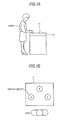
- Figs. 1A and 1B show an example of a computer called a table top type.
- the table-top computer 10 is used, for example, in a hotel counter and the like and a display 11 thereof is disposed on a table surface of the counter or the like.
- the user When a user uses the table-top computer 10, the user is located on a side surface of the display 11 and watches a variety of information (display objects A, B, and C in this example) displayed on the display 11 obliquely from the upside as shown in Fig. 1A .
- the display 11 of the table-top computer 10 is disposed on the table surface of the counter or the like and a physical object (an actual object such as a handbag, a book, and a cup) can be placed thereon.
- US 2008/0231611 discloses that the position of a physical object placed on a display is specified by imaging the display from the upside thereof and a display position of a display object in the display is changed to avoid the position just below the physical object.
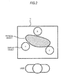
- a display object B may move to the back of the physical object as viewed from the user, for example, as shown in Fig. 2 .
- the user may not watch the display object B depending on the height (the length in the direction perpendicular to the display) of the physical object.
- an image display method which includes detecting a position of a user, detecting a position of a physical object, and defining a non-display area of a display based on the position of the user and the position of the physical object.
- a physical object can be placed on a display disposed on a table surface, like a desk-top computer shown in Figs. 1A and 1B .
- Fig. 3 shows a state where a display object is made to move to avoid a physical object placed on a display by the information processing apparatus according to the embodiment.
- a physical object is placed on the display on the basis of an image signal from an imaging unit built in the display.
- a physical object is placed on the display, as shown in the drawing, a non-display area having an end of the display on the user side and tangent lines L L and L R to the physical object is set and the display position of a display object displayed in the picture of the display moves to an area (hereinafter, referred to as a display area) other than the non-display area.
- a display area an area (hereinafter, referred to as a display area) other than the non-display area.
- a method of setting the non-display area will be described later. Accordingly, it is possible to suppress difficulty in watching the display object regardless of the height of the physical object placed on the display.
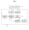
- Fig. 4 shows the configuration of the information processing apparatus according to the embodiment.
- the information processing apparatus 20 includes an operation input unit 21, a display signal generating unit 22, an image signal acquiring unit 23, a physical object detecting unit 24, a user sensing unit 25, a non-display area setting unit 26, a display signal output unit 27, and a display 30 having an imaging unit built therein.
- the operation input unit 21 receives an operation input from a user and outputs an operation signal corresponding thereto to the display signal generating unit 22.
- the display signal generating unit 22 generates a display signal for displaying a picture including a display object and the like on the display 30 having an imaging unit built therein on the basis of the operation signal corresponding to the user' s operation and supplies the generated display signal to the display signal output unit 27.
- the display signal generating unit 22 updates the display signal so as not to locate the display object in the non-display area on the basis of the position information of the non-display area supplied from the non-display area setting unit 26 and supplies the updated display signal to the display signal output unit 27.
- the image signal acquiring unit 23 acquires an image signal from the display 30 having an imaging unit built therein (hereinafter, also simply referred to as a display 30) and outputs the acquired image signal to the physical object detecting unit 24.
- the physical object detecting unit 24 detects a closed curve C representing the profile of the physical object placed on the display 30 on the basis of the image signal from the display 30.
- the user sensing unit 25 senses the side on which the user is located out of four sides surrounding the display 30 and notifies the non-display area setting unit 26 of the sensed side.
- an infrared sensor, an ultrasonic sensor, and a human heat radiation sensor can be used as the user sensing unit 25.
- the position of the user may be sensed by urging the user to place the palm on the display 30 and detecting the profile of the palm on the basis of the image signal thereof.
- the non-display area setting unit 26 sets a non-display area on the basis of the closed curve C representing the profile of the physical object placed on the display 30 and the position of the user and notifies the display signal generating unit 22 of the position information of the set non-display area.
- a method of setting a non-display area will be described below.
- four vertexes of the display 30 are defined as p0 (0, 0), p1 (0, X), p2 (X, Y), p3(0, Y).
- Fig. 5 shows a case where the user is located on the side of p0 and p1.
- the straight line L L passes through the vertex p0 and thus is expressed by Expression (1).
- Straight line L L : y - 0 a ⁇ x - 0
- a function F(x, y) expressed by Expression (2) is defined on the basis of Expression (1).
- Function F x , y y - 0 - a ⁇ x - 0
- the straight line LR is determined similarly. That is, the straight line LR passes through the vertex p1 and thus is expressed by Expression (3).
- Straight line LR : y - 0 a ⁇ x - X
- a function F(x, y) expressed by Expression (4) is defined on the basis of Expression (3).
- Function F x , y y - 0 - a ⁇ x - X
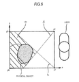
- Fig. 6 shows a case where the user is located on the side of p1 and p2.
- the straight line LL passes through the vertex p1 and thus is expressed by Expression (5).
- Straight line LL : y - 0 a ⁇ x - X
- parameter a is made to increase toward 0 from the negative infinity, and parameter a when the value of the function F (x, y) is first 0 is employed as the slope of the straight line L L .
- the straight line L R is determined similarly. That is, the straight line L R passes through the vertex p2 and thus is expressed by Expression (7).
- Straight line L R : y - Y a ⁇ x - X
- a function F(x, y) expressed by Expression (8) is defined on the basis of Expression (7).
- Function F x , y y - Y - a ⁇ x - X
- the area on the user side with the determined straight lines L L and L R as a boundary is set as the display area and the other area is set as the non-display area.
- a substantially triangular area which may appear between the display area and the closed curve C of the physical object may be set as the display area.
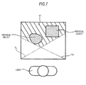
- Fig. 7 shows a case where plural physical objects are placed on the display 30.
- the non-display area is determined for each physical object and the logical sum thereof is set as the non-display area as a whole.
- the area on the user side with the straight lines L L and L R as a boundary is set as the display area.
- the area on the user side with the straight lines L L and L R as a boundary may be changed to the non-display area. This change can be used in the step of concealing information of users from the users, for example, when playing cards, mah-jongg, and the like by the use of the information processing apparatus 20.
- the display signal output unit 27 supplies the display signal input from the display signal generating unit 22 to the display 30.
- the display 30 having an imaging unit built therein, which is disposed on the surface of a table or a counter displays a picture corresponding to the display signal supplied from the display signal output unit 27.
- the display 30 having an imaging unit built therein includes an imaging unit 50 therein.
- the imaging unit 50 images the physical object placed on the display 30 from the inside under the control of the image signal acquiring unit 23 and outputs an image signal, which is obtained as a result and represents the shape of the bottom surface (the surface in contact with the display 30) of the physical object, to the image signal acquiring unit 23.
- Fig. 8 is a sectional view illustrating the configuration of the display 30 having an imaging unit built therein.
- a backlight 31 a polarizing filter 32-1, a glass substrate 33-1, a transparent electrode 34-1, an alignment film 35-1, a liquid crystal 36, an alignment film 35-2, a transparent electrode 34-2, a color filter 37, a glass substrate 33-2, and a polarizing filter 32-2 are stacked sequentially from the inside thereof.
- An imaging unit 50 capturing an image using near-infrared light is disposed inside the glass substrates 33-1 and 33-2.
- a touch panel or the like sensing the user's operation input may be additionally stacked on the polarizing filter 32-2.
- the display 30 having an imaging unit built therein has a structure in which the imaging unit 50 is built in the general configuration of a liquid crystal display.
- the backlight 31 emits near-infrared light (800 to 900 nm), which is applied to the bottom surface of the physical object to enable the imaging unit 50 to receive the reflected, along with visible light for displaying a picture.
- the imaging unit 50 includes an IR filter 51 transmitting only near-infrared light and a light-receiving portion 52 receiving the near-infrared light and converting the received near-infrared light into an image signal.
- the light-receiving portion 52 can employ, for example, a system using photocurrent generated in an active layer or a system using accumulation of electric charges generated due to absorption of light. Since the imaging units 50 are two-dimensionally and periodically arranged to correspond to the respective pixels to be displayed or to groups each including a predetermined number of pixels, image signals output from all the imaging units 50 represent the bottom surface of the placed physical object.
- FIG. 9 is a flowchart illustrating the display position changing process.
- step S1 the display signal generating unit 22 generates a display signal for displaying a picture including a display object and the like on the display 30 having an imaging unit built therein on the basis of the operation signal corresponding to the user's operation and supplies the generated display signal to the display signal output unit 27.
- step S2 the display signal output unit 27 supplies the display signal input from the display signal generating unit 22 to the display 30 having an imaging unit built therein.
- the display 30 having an imaging unit built therein displays a picture corresponding to the display signal supplied from the display signal output unit 27.
- step S3 the image signal acquiring unit 23 acquires an image signal from the display 30 having an imaging unit built therein and outputs the acquired image signal to the physical object detecting unit 24.
- step S4 the physical object detecting unit 24 determines whether a physical object is placed on the display 30 on the basis of the image signal from the display 30. When it is determined that a physical object is not placed on the display, the flow of processes is returned to step S3 and the processes subsequent thereto are repeated.
- step S4 When it is determined in step S4 that a physical object is placed on the display 30, the flow of processes goes to step S5.
- the physical object detecting unit 24 specifies the position of the physical object placed on the display on the basis of the image signal and notifies the non-display area setting unit 26 of a closed curve C representing the profile of the physical object.
- step S6 the user sensing unit 25 senses the side on which the user is located out of four sides surrounding the display 30 and notifies the non-display area setting unit 26 of the sensed side.
- step S7 the non-display area setting unit 26 sets a non-display area on the basis of the closed curve representing the profile of the physical object placed on the display 30 and the position of the user and notifies the display signal generating unit 22 of the position information of the non-display area.
- step S8 the display signal generating unit 22 updates the display signal so as not to locate the display object in the non-display area on the basis of the position information of the non-display area notified from the non-display area setting unit 26 and supplies the updated display signal to the display signal output unit 27. Thereafter, the flow of processes is returned to step S2 and the processes subsequent thereto are repeated. Hitherto, the display position changing process has been described.
- the display position changing process even when a physical object is placed on the display 30 having an imaging unit built therein, it is possible to suppress difficulty in watching a display object in a picture regardless of the height.
- the display position When changing the display position of the display object, the display position may be instantaneously changed or the moving trace of the display object may be visible.
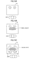
- the moving trace may be a linear trace or a moving trace making a detour of the physical object, for example, as shown in Figs. 10A to 10C .
- the above-mentioned flow of processes may be carried out by hardware or by software.
- a program constituting the software is installed in a computer mounted on dedicated hardware or a general-purpose personal computer which can perform various functions by installing various programs from a program recording medium.
- Fig. 11 is a block diagram illustrating the hardware configuration of a computer executing the flow of processes through the use of the program.
- a central processing unit (CPU) 101 a read only memory (ROM) 102, and a random access memory (RAM) 103 are connected to each other via a bus 104.
- CPU central processing unit
- ROM read only memory
- RAM random access memory
- An input and output interface 105 is further connected to the bus 104.
- the input and output interface 105 is connected to an input unit 106 including a keyboard, a mouse, and a microphone, an output unit 107 including a display and a speaker, a storage unit 108 including a hard disk or a nonvolatile memory, a communication unit 109 including a network interface, and a drive 210 driving a removable medium 211 such as a magnetic disk, an optical disk, a magneto-optical disk, and a semiconductor memory.
- the CPU 101 performs the above-mentioned flow of processes, for example, by loading the program stored in the storage unit 108 to the RAM 103 via the input and output interface 105 and the bus 104 and executing the loaded program.
- the program executed by the computer may be a program performing the flow of processes in time series in the order described in the present disclosure or may be a program performing the flow of processes in parallel or at a demanded time such as a called time.
- the program may be processed by a single computer or may be distributed and processed by plural computers.
- the program may be transmitted to a remote computer and may be executed thereby.
Landscapes
- Engineering & Computer Science (AREA)
- Theoretical Computer Science (AREA)
- Physics & Mathematics (AREA)
- General Physics & Mathematics (AREA)
- General Engineering & Computer Science (AREA)
- Computer Hardware Design (AREA)
- Human Computer Interaction (AREA)
- User Interface Of Digital Computer (AREA)
- Controls And Circuits For Display Device (AREA)
- Processing Or Creating Images (AREA)
- Digital Computer Display Output (AREA)
Abstract
This allows to modify the displayed image by moving a displayed object outside or inside the non-display area.
Description
- The present application claims priority from Japanese Patent Application No.
JP 2011-124909 - The present disclosure relates to an information processing apparatus, an information processing method, and a program, and more particularly, to an information processing apparatus, an information processing method, and a program which can be suitably used in a case where a physical object can be placed on a display disposed on a table surface.
-
Figs. 1A and 1B show an example of a computer called a table top type. The table-top computer 10 is used, for example, in a hotel counter and the like and adisplay 11 thereof is disposed on a table surface of the counter or the like. - When a user uses the table-
top computer 10, the user is located on a side surface of thedisplay 11 and watches a variety of information (display objects A, B, and C in this example) displayed on thedisplay 11 obliquely from the upside as shown inFig. 1A . - The
display 11 of the table-top computer 10 is disposed on the table surface of the counter or the like and a physical object (an actual object such as a handbag, a book, and a cup) can be placed thereon. - However, when a physical object is placed on the
display 11, the display objects displayed thereon at that time is not visible by the user and thus a certain countermeasure is necessary. - For example,
US 2008/0231611 discloses that the position of a physical object placed on a display is specified by imaging the display from the upside thereof and a display position of a display object in the display is changed to avoid the position just below the physical object. - However, only by simply changing the display position of the display object to avoid the position just below the physical object, a display object B may move to the back of the physical object as viewed from the user, for example, as shown in
Fig. 2 . In this case, the user may not watch the display object B depending on the height (the length in the direction perpendicular to the display) of the physical object. - It is therefore desirable to cause a display object to move so as to easily watch the display object when a physical object is placed on a display.
- Accordingly, the embodiments of the present disclosure are provided. According to an illustrative embodiment, an image display method is provided, which includes detecting a position of a user, detecting a position of a physical object, and defining a non-display area of a display based on the position of the user and the position of the physical object.
- Further particular and preferred aspects of the present invention are set out in the accompanying independent and dependent claims. Features of the dependent claims may be combined with features of the independent claims as appropriate, and in combinations other than those explicitly set out in the claims.
- The present invention will be described further, by way of example only, with reference to preferred embodiments thereof as illustrated in the accompanying drawings, in which:
-
-
Figs. 1A and 1B are diagrams illustrating an example of a table-top computer. -
Fig. 2 is a diagram illustrating a state where a display object is made to move from the position just below a physical object placed on a display. -
Fig. 3 is a diagram illustrating a state where a display object is made to move so as to avoid the physical object placed on the display according to an embodiment. -
Fig. 4 is a block diagram illustrating the configuration of an information processing apparatus according to an embodiment. -
Fig. 5 is a diagram illustrating a non-display area setting method. -
Fig. 6 is a diagram illustrating a non-display area setting method. -
Fig. 7 is a diagram illustrating a non-display area setting method. -
Fig. 8 is a sectional view illustrating the configuration of a display having an imaging unit built therein. -
Fig. 9 is a flowchart illustrating a display position changing process. -
Figs. 10A to 10C are diagrams illustrating a movement trace of a display object. -
Fig. 11 is a block diagram illustrating the configuration of a computer. - Hereinafter, a best mode (hereinafter, referred to as an embodiment) for putting the present disclosure into practice will be described in detail with reference to the accompanying drawings.
- In an information processing apparatus according to an embodiment of the present disclosure, a physical object can be placed on a display disposed on a table surface, like a desk-top computer shown in
Figs. 1A and 1B . -
Fig. 3 shows a state where a display object is made to move to avoid a physical object placed on a display by the information processing apparatus according to the embodiment. - In the information processing apparatus according to the embodiment, it is detected that a physical object is placed on the display on the basis of an image signal from an imaging unit built in the display. When a physical object is placed on the display, as shown in the drawing, a non-display area having an end of the display on the user side and tangent lines LL and LR to the physical object is set and the display position of a display object displayed in the picture of the display moves to an area (hereinafter, referred to as a display area) other than the non-display area. A method of setting the non-display area will be described later. Accordingly, it is possible to suppress difficulty in watching the display object regardless of the height of the physical object placed on the display.
-
Fig. 4 shows the configuration of the information processing apparatus according to the embodiment. Theinformation processing apparatus 20 includes anoperation input unit 21, a displaysignal generating unit 22, an imagesignal acquiring unit 23, a physicalobject detecting unit 24, auser sensing unit 25, a non-displayarea setting unit 26, a displaysignal output unit 27, and adisplay 30 having an imaging unit built therein. - The
operation input unit 21 receives an operation input from a user and outputs an operation signal corresponding thereto to the displaysignal generating unit 22. The displaysignal generating unit 22 generates a display signal for displaying a picture including a display object and the like on thedisplay 30 having an imaging unit built therein on the basis of the operation signal corresponding to the user' s operation and supplies the generated display signal to the displaysignal output unit 27. The displaysignal generating unit 22 updates the display signal so as not to locate the display object in the non-display area on the basis of the position information of the non-display area supplied from the non-displayarea setting unit 26 and supplies the updated display signal to the displaysignal output unit 27. - The image
signal acquiring unit 23 acquires an image signal from thedisplay 30 having an imaging unit built therein (hereinafter, also simply referred to as a display 30) and outputs the acquired image signal to the physicalobject detecting unit 24. The physicalobject detecting unit 24 detects a closed curve C representing the profile of the physical object placed on thedisplay 30 on the basis of the image signal from thedisplay 30. - The
user sensing unit 25 senses the side on which the user is located out of four sides surrounding thedisplay 30 and notifies the non-displayarea setting unit 26 of the sensed side. For example, an infrared sensor, an ultrasonic sensor, and a human heat radiation sensor can be used as theuser sensing unit 25. Alternatively, the position of the user may be sensed by urging the user to place the palm on thedisplay 30 and detecting the profile of the palm on the basis of the image signal thereof. - The non-display
area setting unit 26 sets a non-display area on the basis of the closed curve C representing the profile of the physical object placed on thedisplay 30 and the position of the user and notifies the displaysignal generating unit 22 of the position information of the set non-display area. - A method of setting a non-display area will be described below. Hereinafter, four vertexes of the
display 30 are defined as p0 (0, 0), p1 (0, X), p2 (X, Y), p3(0, Y). -
Fig. 5 shows a case where the user is located on the side of p0 and p1. In this case, the straight line LL passes through the vertex p0 and thus is expressed by Expression (1).
- A function F(x, y) expressed by Expression (2) is defined on the basis of Expression (1).

- The values of the function F(x, y) for all points c(xc, yc) in the existing closed curve C are calculated, parameter a is made to increase in the positive direction from 0, and parameter a when the value of the function F(x, y) is first 0 is employed as the slope of the straight line LL.
- The straight line LR is determined similarly. That is, the straight line LR passes through the vertex p1 and thus is expressed by Expression (3).

- A function F(x, y) expressed by Expression (4) is defined on the basis of Expression (3).

- The values of the function F(x, y) for all points c(xc, yc) in the existing closed curve C are calculated, parameter a is made to decrease in the negative direction from 0, and parameter a when the value of the function F(x, y) is first 0 is employed as the slope of the straight line LR.
-
Fig. 6 shows a case where the user is located on the side of p1 and p2. In this case, the straight line LL passes through the vertex p1 and thus is expressed by Expression (5).
- A function F(x, y) expressed by Expression (6) is defined on the basis of Expression (5).

- The values of the function F(x, y) for all points c (xc, yc) in the existing closed curve C, parameter a is made to increase toward 0 from the negative infinity, and parameter a when the value of the function F (x, y) is first 0 is employed as the slope of the straight line LL.
- The straight line LR is determined similarly. That is, the straight line LR passes through the vertex p2 and thus is expressed by Expression (7).

- A function F(x, y) expressed by Expression (8) is defined on the basis of Expression (7).

- The values of the function F(x, y) for all points c(xc, yc) in the existing closed curve C are calculated, parameter a is made to decrease toward 0 from the positive infinity, and parameter a when the value of the function F(x, y) is first 0 is employed as the slope of the straight line LR.
- When the user is located on the side of p2 and p3 and when the user is located on the side of p3 and p0, the straight lines LL and LR are determined similarly.
- The area on the user side with the determined straight lines LL and LR as a boundary is set as the display area and the other area is set as the non-display area. A substantially triangular area which may appear between the display area and the closed curve C of the physical object may be set as the display area.
-
Fig. 7 shows a case where plural physical objects are placed on thedisplay 30. In this case, the non-display area is determined for each physical object and the logical sum thereof is set as the non-display area as a whole. - In this embodiment, the area on the user side with the straight lines LL and LR as a boundary is set as the display area. On the contrary, the area on the user side with the straight lines LL and LR as a boundary may be changed to the non-display area. This change can be used in the step of concealing information of users from the users, for example, when playing cards, mah-jongg, and the like by the use of the
information processing apparatus 20. -
Fig. 4 will be referred to again. The displaysignal output unit 27 supplies the display signal input from the displaysignal generating unit 22 to thedisplay 30. Thedisplay 30 having an imaging unit built therein, which is disposed on the surface of a table or a counter displays a picture corresponding to the display signal supplied from the displaysignal output unit 27. Thedisplay 30 having an imaging unit built therein includes animaging unit 50 therein. Theimaging unit 50 images the physical object placed on thedisplay 30 from the inside under the control of the imagesignal acquiring unit 23 and outputs an image signal, which is obtained as a result and represents the shape of the bottom surface (the surface in contact with the display 30) of the physical object, to the imagesignal acquiring unit 23. -
Fig. 8 is a sectional view illustrating the configuration of thedisplay 30 having an imaging unit built therein. - In the
display 30 having an imaging unit built therein, abacklight 31, a polarizing filter 32-1, a glass substrate 33-1, a transparent electrode 34-1, an alignment film 35-1, a liquid crystal 36, an alignment film 35-2, a transparent electrode 34-2, acolor filter 37, a glass substrate 33-2, and a polarizing filter 32-2 are stacked sequentially from the inside thereof. Animaging unit 50 capturing an image using near-infrared light is disposed inside the glass substrates 33-1 and 33-2. A touch panel or the like sensing the user's operation input may be additionally stacked on the polarizing filter 32-2. - That is, the
display 30 having an imaging unit built therein has a structure in which theimaging unit 50 is built in the general configuration of a liquid crystal display. Here, it is assumed that thebacklight 31 emits near-infrared light (800 to 900 nm), which is applied to the bottom surface of the physical object to enable theimaging unit 50 to receive the reflected, along with visible light for displaying a picture. - The
imaging unit 50 includes anIR filter 51 transmitting only near-infrared light and a light-receivingportion 52 receiving the near-infrared light and converting the received near-infrared light into an image signal. The light-receivingportion 52 can employ, for example, a system using photocurrent generated in an active layer or a system using accumulation of electric charges generated due to absorption of light. Since theimaging units 50 are two-dimensionally and periodically arranged to correspond to the respective pixels to be displayed or to groups each including a predetermined number of pixels, image signals output from all theimaging units 50 represent the bottom surface of the placed physical object. - A display position changing process in the
information processing apparatus 20 will be described below.Fig. 9 is a flowchart illustrating the display position changing process. - In step S1, the display
signal generating unit 22 generates a display signal for displaying a picture including a display object and the like on thedisplay 30 having an imaging unit built therein on the basis of the operation signal corresponding to the user's operation and supplies the generated display signal to the displaysignal output unit 27. - In step S2, the display
signal output unit 27 supplies the display signal input from the displaysignal generating unit 22 to thedisplay 30 having an imaging unit built therein. Thedisplay 30 having an imaging unit built therein displays a picture corresponding to the display signal supplied from the displaysignal output unit 27. - In step S3, the image
signal acquiring unit 23 acquires an image signal from thedisplay 30 having an imaging unit built therein and outputs the acquired image signal to the physicalobject detecting unit 24. In step S4, the physicalobject detecting unit 24 determines whether a physical object is placed on thedisplay 30 on the basis of the image signal from thedisplay 30. When it is determined that a physical object is not placed on the display, the flow of processes is returned to step S3 and the processes subsequent thereto are repeated. - When it is determined in step S4 that a physical object is placed on the
display 30, the flow of processes goes to step S5. In step S5, the physicalobject detecting unit 24 specifies the position of the physical object placed on the display on the basis of the image signal and notifies the non-displayarea setting unit 26 of a closed curve C representing the profile of the physical object. - In step S6, the
user sensing unit 25 senses the side on which the user is located out of four sides surrounding thedisplay 30 and notifies the non-displayarea setting unit 26 of the sensed side. In step S7, the non-displayarea setting unit 26 sets a non-display area on the basis of the closed curve representing the profile of the physical object placed on thedisplay 30 and the position of the user and notifies the displaysignal generating unit 22 of the position information of the non-display area. - In step S8, the display
signal generating unit 22 updates the display signal so as not to locate the display object in the non-display area on the basis of the position information of the non-display area notified from the non-displayarea setting unit 26 and supplies the updated display signal to the displaysignal output unit 27. Thereafter, the flow of processes is returned to step S2 and the processes subsequent thereto are repeated. Hitherto, the display position changing process has been described. - According to the display position changing process, even when a physical object is placed on the
display 30 having an imaging unit built therein, it is possible to suppress difficulty in watching a display object in a picture regardless of the height. - When changing the display position of the display object, the display position may be instantaneously changed or the moving trace of the display object may be visible. The moving trace may be a linear trace or a moving trace making a detour of the physical object, for example, as shown in
Figs. 10A to 10C . - The above-mentioned flow of processes may be carried out by hardware or by software. When the flow of processes is carried out by software, a program constituting the software is installed in a computer mounted on dedicated hardware or a general-purpose personal computer which can perform various functions by installing various programs from a program recording medium.
-
Fig. 11 is a block diagram illustrating the hardware configuration of a computer executing the flow of processes through the use of the program. - In the
computer 100, a central processing unit (CPU) 101, a read only memory (ROM) 102, and a random access memory (RAM) 103 are connected to each other via abus 104. - An input and
output interface 105 is further connected to thebus 104. The input andoutput interface 105 is connected to aninput unit 106 including a keyboard, a mouse, and a microphone, anoutput unit 107 including a display and a speaker, astorage unit 108 including a hard disk or a nonvolatile memory, acommunication unit 109 including a network interface, and a drive 210 driving a removable medium 211 such as a magnetic disk, an optical disk, a magneto-optical disk, and a semiconductor memory. - In the
computer 100 having the above-mentioned configuration, theCPU 101 performs the above-mentioned flow of processes, for example, by loading the program stored in thestorage unit 108 to theRAM 103 via the input andoutput interface 105 and thebus 104 and executing the loaded program. - The program executed by the computer may be a program performing the flow of processes in time series in the order described in the present disclosure or may be a program performing the flow of processes in parallel or at a demanded time such as a called time.
- The program may be processed by a single computer or may be distributed and processed by plural computers. The program may be transmitted to a remote computer and may be executed thereby.
- Particular embodiments of the present disclosure include the following.
- (1) An image display method including: detecting a position of a user; detecting a position of a physical object; and defining a non-display area of a display based on the position of the user and the position of the physical object.
- (2) The method according to (1), further including modifying an image to be displayed on the display to move a display object outside the non-display area.
- (3) The method according to (1) or (2), further including modifying an image to be displayed on the display to move a display object into the non-display area.
- (4) The method according to any one of (1) to (3), wherein detecting the physical object includes detecting a closed curve representing the physical object.
- (5) The method according to (4), wherein the non-display area is defined on the basis of the closed curve.
- (6) The method according to any one (1) to (5), wherein the non-display area is defined according to two lines which partition a surface of the display.
- (7) The method according to any one of (1) to (6), wherein defining a non-display area includes defining a non-display area based on respective positions of two or more physical objects and the position of the user, and wherein the non-display area is determined by determining respective non-display areas for the physical objects and generating a logical sum of the respective non-display areas.
- (8) The method according to any one of (1) to (7), wherein detecting the physical object comprises using an imaging unit.
- (9) The method according to (8), wherein the imaging unit is a near-infrared imaging unit.
- (10) The method according to any one of (1) to (9), wherein detecting the position of the user includes at least one of using an infrared sensor, using an ultrasonic sensor, using a human heat radiation sensor, and detecting a profile of the user's palm.
- (11) An image display apparatus including a processing circuit for detecting a position of a user, detecting a position of a physical object, and defining a non-display area of a display based on the position of the user and the position of the physical object.
- (12) The apparatus according to (11), wherein the display is integral to the apparatus.
- (13) The apparatus according to (11) or (12), further including an imaging unit for detecting the physical object.
- (14) The apparatus according to (13), wherein the imaging unit is a near-infrared imaging unit.
- (15) The apparatus according to (13) or (14), wherein the display includes a backlight and a liquid crystal, and the imaging unit is positioned between the backlight and the liquid crystal.
- (16) The apparatus according to any one of (11) to (16), wherein an image to be displayed on the display is modified to move a display object outside the non-display area.
- (17) The apparatus according to (16), wherein the display object is moved gradually and a trace of the display object's movement is displayed.
- (18) The apparatus according to any one of (11) to (17), wherein an image to be displayed on the display is modified to move a display object into the non-display area.
- (19) An image display apparatus including: means for detecting a position of a user; means for detecting a position of a physical object; and means for defining a non-display area of a display based on the position of the user and the position of the physical object.
- (20) A non-transitory computer-readable medium having stored thereon a computer-readable program for implementing an image display method including: detecting a position of a user; detecting a position of a physical object; and defining a non-display area of a display based on the position of the user and the position of the physical object.
- The present disclosure is not limited to the above-mentioned embodiments, but may be modified in various forms without departing from the concept of the present disclosure.
- Although particular embodiments have been described herein, it will be appreciated that the invention is not limited thereto and that many modifications and additions thereto may be made within the scope of the invention. For example, various combinations of the features of the following dependent claims can be made with the features of the independent claims without departing from the scope of the present invention.
- In so far as the embodiments of the invention described above are implemented, at least in part, using software-controlled data processing apparatus, it will be appreciated that a computer program providing such software control and a transmission, storage or other medium by which such a computer program is provided are envisaged as aspects of the present invention.
Claims (15)
- An image display method comprising:detecting a position of a user;detecting a position of a physical object; anddefining a non-display area of a display based on the position of the user and the position of the physical object.
- The method as recited in claim 1, further comprising modifying an image to be displayed on the display to move a display object outside the non-display area.
- The method as recited in claim 1, further comprising modifying an image to be displayed on the display to move a display object into the non-display area.
- The method as recited in claim 1, wherein detecting the physical object comprises detecting a closed curve representing the physical object.
- The method as recited in claim 4, wherein the non-display area is defined on the basis of the closed curve.
- The method as recited in claim 1, wherein the non-display area is defined according to two lines which partition a surface of the display.
- The method as recited in claim 1, wherein defining a non-display area comprises defining a non-display area based on respective positions of two or more physical objects and the position of the user, and wherein the non-display area is determined by determining respective non-display areas for the physical objects and generating a logical sum of the respective non-display areas.
- An image display apparatus comprising a processing circuit for detecting a position of a user, detecting a position of a physical object, and defining a non-display area of a display based on the position of the user and the position of the physical object.
- The apparatus as recited in claim 8, further comprising an imaging unit for detecting the physical object.
- The apparatus as recited in claim 9, wherein the imaging unit is a near-infrared imaging unit.
- The apparatus as recited in claim 9, wherein the display further comprises a backlight and a liquid crystal, and the imaging unit is positioned between the backlight and the liquid crystal.
- The apparatus as recited in claim 8, wherein an image to be displayed on the display is modified to move a display object outside the non-display area.
- The apparatus as recited in claim 12, wherein the display object is moved gradually and a trace of the display object's movement is displayed.
- The apparatus as recited in claim 8, wherein an image to be displayed on the display is modified to move a display object into the non-display area.
- A non-transitory computer-readable medium having stored thereon a computer-readable program for implementing an image display method comprising
detecting a position of a user;
detecting a position of a physical object; and defining a non-display area of a display based on the position of the user and the position of the physical object.
Applications Claiming Priority (1)
| Application Number | Priority Date | Filing Date | Title |
|---|---|---|---|
| JP2011124909A JP5880916B2 (en) | 2011-06-03 | 2011-06-03 | Information processing apparatus, information processing method, and program |
Publications (3)
| Publication Number | Publication Date |
|---|---|
| EP2529805A2 true EP2529805A2 (en) | 2012-12-05 |
| EP2529805A3 EP2529805A3 (en) | 2013-03-20 |
| EP2529805B1 EP2529805B1 (en) | 2015-07-01 |
Family
ID=46125316
Family Applications (1)
| Application Number | Title | Priority Date | Filing Date |
|---|---|---|---|
| EP12169532.4A Not-in-force EP2529805B1 (en) | 2011-06-03 | 2012-05-25 | Information processing apparatus, information processing method, and program, which upon display of an image take into account the position of a physical object placed on the display |
Country Status (4)
| Country | Link |
|---|---|
| US (2) | US10152953B2 (en) |
| EP (1) | EP2529805B1 (en) |
| JP (1) | JP5880916B2 (en) |
| CN (1) | CN102981602B (en) |
Families Citing this family (7)
| Publication number | Priority date | Publication date | Assignee | Title |
|---|---|---|---|---|
| CN105308670B (en) * | 2014-01-22 | 2017-12-29 | 堺显示器制品株式会社 | Display device |
| WO2015111157A1 (en) * | 2014-01-22 | 2015-07-30 | 堺ディスプレイプロダクト株式会社 | Display device |
| CN105242813B (en) * | 2014-06-20 | 2020-11-06 | 鸿合科技股份有限公司 | Method and device for identifying object based on infrared screen |
| JP2018116471A (en) * | 2017-01-18 | 2018-07-26 | 富士通株式会社 | Display control method, apparatus and program |
| US10613960B2 (en) * | 2017-07-31 | 2020-04-07 | Mitsubishi Electric Corporation | Information processing apparatus and information processing method |
| GB2568695B (en) * | 2017-11-23 | 2019-11-20 | Ford Global Tech Llc | Vehicle display system and method |
| US11188154B2 (en) * | 2018-05-30 | 2021-11-30 | International Business Machines Corporation | Context dependent projection of holographic objects |
Citations (2)
| Publication number | Priority date | Publication date | Assignee | Title |
|---|---|---|---|---|
| US20080231611A1 (en) | 2004-04-29 | 2008-09-25 | Microsoft Corporation | Interaction between objects and a virtual environment display |
| JP2011124909A (en) | 2009-12-14 | 2011-06-23 | Nintendo Co Ltd | Network system, communication terminal and communication program |
Family Cites Families (53)
| Publication number | Priority date | Publication date | Assignee | Title |
|---|---|---|---|---|
| US6614422B1 (en) * | 1999-11-04 | 2003-09-02 | Canesta, Inc. | Method and apparatus for entering data using a virtual input device |
| US7730430B2 (en) * | 2003-01-24 | 2010-06-01 | Microsoft Corporation | High density cursor system and method |
| JP3809423B2 (en) | 2003-03-07 | 2006-08-16 | キヤノン株式会社 | Display device and control method of display device |
| JP3874737B2 (en) | 2003-03-31 | 2007-01-31 | 株式会社東芝 | Display device |
| JP2004304718A (en) * | 2003-04-01 | 2004-10-28 | Nara Institute Of Science & Technology | Proximity region image extraction device and proximity region image extraction method |
| JP4151483B2 (en) | 2003-06-10 | 2008-09-17 | ソニー株式会社 | Bioassay substrate and bioassay apparatus and method |
| JP4095040B2 (en) | 2004-02-12 | 2008-06-04 | 株式会社日立製作所 | Display method of table type information terminal |
| US20050212914A1 (en) | 2004-03-25 | 2005-09-29 | Fuji Photo Film Co., Ltd. | Method, apparatus, system, and computer executable program for image processing |
| US7925070B2 (en) * | 2004-03-30 | 2011-04-12 | Sysmex Corporation | Method for displaying virtual slide and terminal device for displaying virtual slide |
| JP2005345709A (en) | 2004-06-02 | 2005-12-15 | Fuji Photo Film Co Ltd | Image display control table, image interference evasion method, and image interference evasion program |
| US7519223B2 (en) * | 2004-06-28 | 2009-04-14 | Microsoft Corporation | Recognizing gestures and using gestures for interacting with software applications |
| US7728821B2 (en) | 2004-08-06 | 2010-06-01 | Touchtable, Inc. | Touch detecting interactive display |
| JP2006100661A (en) | 2004-09-30 | 2006-04-13 | Sony Corp | Method for manufacturing thin film semiconductor device |
| US7626569B2 (en) | 2004-10-25 | 2009-12-01 | Graphics Properties Holdings, Inc. | Movable audio/video communication interface system |
| JP4645179B2 (en) * | 2004-12-02 | 2011-03-09 | 株式会社デンソー | Vehicle navigation device |
| US8040361B2 (en) * | 2005-04-11 | 2011-10-18 | Systems Technology, Inc. | Systems and methods for combining virtual and real-time physical environments |
| US7479967B2 (en) * | 2005-04-11 | 2009-01-20 | Systems Technology Inc. | System for combining virtual and real-time environments |
| EP1722295A1 (en) * | 2005-05-10 | 2006-11-15 | Siemens Aktiengesellschaft | Method, apparatus and computer program product for providing user information in a graphical user interface |
| US20070064004A1 (en) | 2005-09-21 | 2007-03-22 | Hewlett-Packard Development Company, L.P. | Moving a graphic element |
| JP2007133489A (en) * | 2005-11-08 | 2007-05-31 | Sony Corp | Virtual space image display method, apparatus, virtual space image display program, and recording medium |
| US7620901B2 (en) | 2006-03-21 | 2009-11-17 | Microsoft Corporation | Simultaneous input across multiple applications |
| US7876333B2 (en) * | 2006-03-30 | 2011-01-25 | Smart Technologies Ulc | Method and graphical interface for embedding animated content into a computer application |
| US8736547B2 (en) * | 2006-04-20 | 2014-05-27 | Hewlett-Packard Development Company, L.P. | Method and system for interfacing a digital device with an interactive display surface |
| US7552402B2 (en) * | 2006-06-22 | 2009-06-23 | Microsoft Corporation | Interface orientation using shadows |
| EP2050088B1 (en) | 2006-07-28 | 2015-11-11 | Koninklijke Philips N.V. | Private screens self distributing along the shop window |
| JP4973245B2 (en) | 2007-03-08 | 2012-07-11 | 富士ゼロックス株式会社 | Display device and program |
| US7733343B2 (en) * | 2007-06-25 | 2010-06-08 | Hewlett-Packard Development Company, L.P. | Virtual shadow for physical object placed on surface |
| JP4595976B2 (en) * | 2007-08-28 | 2010-12-08 | 株式会社デンソー | Video processing apparatus and camera |
| US8884883B2 (en) * | 2008-01-25 | 2014-11-11 | Microsoft Corporation | Projection of graphical objects on interactive irregular displays |
| US8233206B2 (en) | 2008-03-18 | 2012-07-31 | Zebra Imaging, Inc. | User interaction with holographic images |
| US8584029B1 (en) * | 2008-05-23 | 2013-11-12 | Intuit Inc. | Surface computer system and method for integrating display of user interface with physical objects |
| US20100209069A1 (en) * | 2008-09-18 | 2010-08-19 | Dennis Fountaine | System and Method for Pre-Engineering Video Clips |
| US20100141553A1 (en) | 2008-12-04 | 2010-06-10 | Ma Lighting Technology Gmbh | Method for operating a display system |
| US8289288B2 (en) * | 2009-01-15 | 2012-10-16 | Microsoft Corporation | Virtual object adjustment via physical object detection |
| US20100182340A1 (en) * | 2009-01-19 | 2010-07-22 | Bachelder Edward N | Systems and methods for combining virtual and real-time physical environments |
| US20110267374A1 (en) | 2009-02-05 | 2011-11-03 | Kotaro Sakata | Information display apparatus and information display method |
| TWI372561B (en) * | 2009-04-07 | 2012-09-11 | Univ Nat Taiwan | Method for decomposition and rending of video content and user interface operating the method thereof |
| WO2010148078A2 (en) * | 2009-06-16 | 2010-12-23 | Simquest Llc | Hemorrhage control simulator |
| WO2011004135A1 (en) * | 2009-07-07 | 2011-01-13 | Elliptic Laboratories As | Control using movements |
| CN101655771B (en) * | 2009-09-07 | 2011-07-20 | 上海合合信息科技发展有限公司 | Method and system for inputting multi-contact characters |
| JP5296218B2 (en) * | 2009-09-28 | 2013-09-25 | 株式会社東芝 | 3D image display method and 3D image display apparatus |
| US20110187664A1 (en) | 2010-02-02 | 2011-08-04 | Mark Rinehart | Table computer systems and methods |
| JP5573238B2 (en) * | 2010-03-04 | 2014-08-20 | ソニー株式会社 | Information processing apparatus, information processing method and program |
| JP5451497B2 (en) * | 2010-04-08 | 2014-03-26 | パナソニック株式会社 | Driving support display device |
| US20110263326A1 (en) | 2010-04-26 | 2011-10-27 | Wms Gaming, Inc. | Projecting and controlling wagering games |
| TWI473026B (en) | 2010-06-30 | 2015-02-11 | 鴻海精密工業股份有限公司 | Image processing system, display device and image display method |
| US8593418B2 (en) * | 2010-08-08 | 2013-11-26 | Qualcomm Incorporated | Method and system for adjusting display content |
| WO2012065146A2 (en) | 2010-11-12 | 2012-05-18 | Wms Gaming, Inc. | Integrating three-dimensional elements into gaming environments |
| BE1019842A5 (en) * | 2011-02-09 | 2013-01-08 | Cyrpa Internat | DEVICE AND METHOD FOR ADJUSTING AND POSITIONING USING LASER SYSTEMS. |
| JP4989768B2 (en) * | 2011-02-24 | 2012-08-01 | 任天堂株式会社 | Image processing program, image processing apparatus, image processing system, and image processing method |
| JP5873256B2 (en) | 2011-05-23 | 2016-03-01 | 株式会社東芝 | X-ray diagnostic equipment |
| US9345957B2 (en) * | 2011-09-30 | 2016-05-24 | Microsoft Technology Licensing, Llc | Enhancing a sport using an augmented reality display |
| JP5929572B2 (en) | 2012-07-09 | 2016-06-08 | コニカミノルタ株式会社 | Operation display device and program |
-
2011
- 2011-06-03 JP JP2011124909A patent/JP5880916B2/en not_active Expired - Fee Related
-
2012
- 2012-05-09 US US13/467,379 patent/US10152953B2/en active Active
- 2012-05-25 EP EP12169532.4A patent/EP2529805B1/en not_active Not-in-force
- 2012-05-25 CN CN201210166580.2A patent/CN102981602B/en not_active Expired - Fee Related
-
2016
- 2016-10-28 US US15/336,977 patent/US10176787B2/en active Active
Patent Citations (2)
| Publication number | Priority date | Publication date | Assignee | Title |
|---|---|---|---|---|
| US20080231611A1 (en) | 2004-04-29 | 2008-09-25 | Microsoft Corporation | Interaction between objects and a virtual environment display |
| JP2011124909A (en) | 2009-12-14 | 2011-06-23 | Nintendo Co Ltd | Network system, communication terminal and communication program |
Also Published As
| Publication number | Publication date |
|---|---|
| US20120306932A1 (en) | 2012-12-06 |
| CN102981602B (en) | 2017-03-01 |
| US10176787B2 (en) | 2019-01-08 |
| US20170047049A1 (en) | 2017-02-16 |
| US10152953B2 (en) | 2018-12-11 |
| JP2012252543A (en) | 2012-12-20 |
| CN102981602A (en) | 2013-03-20 |
| EP2529805B1 (en) | 2015-07-01 |
| EP2529805A3 (en) | 2013-03-20 |
| JP5880916B2 (en) | 2016-03-09 |
Similar Documents
| Publication | Publication Date | Title |
|---|---|---|
| US10176787B2 (en) | Information processing apparatus and information processing method for occlusion avoidance in tabletop displays | |
| JP7593985B2 (en) | Electronic Devices | |
| EP2203982B1 (en) | Detecting finger orientation on a touch-sensitive device | |
| KR101451735B1 (en) | Electronic device and method for driving a touch sensor thereof | |
| US20180103194A1 (en) | Image capture systems, devices, and methods that autofocus based on eye-tracking | |
| US8330777B2 (en) | Information processing method, touch information processing device, and flat panel display | |
| US8884894B2 (en) | Input detection device, input detection method, input detection program, and computer readable media | |
| EP2367352B1 (en) | Imaging apparatus and method | |
| CN105829948B (en) | Wearable Display Input System | |
| KR20170056704A (en) | Integrated self-capacitive touch display | |
| US11057606B2 (en) | Method and display system for information display based on positions of human gaze and object | |
| CN105308670B (en) | Display device | |
| US11036335B2 (en) | Method, apparatus and storage medium for calibrating capacitive touch module | |
| TW200844809A (en) | Display apparatus | |
| US20190302989A1 (en) | Display control method and electronic device thereof | |
| KR20180081885A (en) | Electronic device | |
| US11216115B2 (en) | Electronic device and method for controlling touch sensing signals and storage medium | |
| US20220358689A1 (en) | Curated contextual overlays for augmented reality experiences | |
| CN109949732A (en) | Display device, control method and recording medium | |
| US9674512B2 (en) | Method, apparatus and cell for displaying three-dimensional object | |
| TWI471799B (en) | Method and system for processing stereoscopic image with interacting function | |
| JP2016012377A (en) | Information processing device, information processing method and program | |
| US20150293645A1 (en) | Holographic collection and emission turning film system | |
| US20120007855A1 (en) | Converting method, device and system for 3d stereoscopic cartoon, and recording medium for the same | |
| US20180239487A1 (en) | Information processing device, information processing method, and program |
Legal Events
| Date | Code | Title | Description |
|---|---|---|---|
| PUAI | Public reference made under article 153(3) epc to a published international application that has entered the european phase |
Free format text: ORIGINAL CODE: 0009012 |
|
| 17P | Request for examination filed |
Effective date: 20120614 |
|
| AK | Designated contracting states |
Kind code of ref document: A2 Designated state(s): AL AT BE BG CH CY CZ DE DK EE ES FI FR GB GR HR HU IE IS IT LI LT LU LV MC MK MT NL NO PL PT RO RS SE SI SK SM TR |
|
| AX | Request for extension of the european patent |
Extension state: BA ME |
|
| PUAL | Search report despatched |
Free format text: ORIGINAL CODE: 0009013 |
|
| AK | Designated contracting states |
Kind code of ref document: A3 Designated state(s): AL AT BE BG CH CY CZ DE DK EE ES FI FR GB GR HR HU IE IS IT LI LT LU LV MC MK MT NL NO PL PT RO RS SE SI SK SM TR |
|
| AX | Request for extension of the european patent |
Extension state: BA ME |
|
| RIC1 | Information provided on ipc code assigned before grant |
Ipc: A63F 13/00 20060101AFI20130211BHEP Ipc: G06T 17/00 20060101ALI20130211BHEP Ipc: G06T 15/20 20110101ALI20130211BHEP Ipc: G06T 15/40 20110101ALI20130211BHEP Ipc: G09G 5/38 20060101ALI20130211BHEP |
|
| 17Q | First examination report despatched |
Effective date: 20131001 |
|
| GRAP | Despatch of communication of intention to grant a patent |
Free format text: ORIGINAL CODE: EPIDOSNIGR1 |
|
| INTG | Intention to grant announced |
Effective date: 20150112 |
|
| GRAS | Grant fee paid |
Free format text: ORIGINAL CODE: EPIDOSNIGR3 |
|
| GRAA | (expected) grant |
Free format text: ORIGINAL CODE: 0009210 |
|
| AK | Designated contracting states |
Kind code of ref document: B1 Designated state(s): AL AT BE BG CH CY CZ DE DK EE ES FI FR GB GR HR HU IE IS IT LI LT LU LV MC MK MT NL NO PL PT RO RS SE SI SK SM TR |
|
| REG | Reference to a national code |
Ref country code: GB Ref legal event code: FG4D |
|
| REG | Reference to a national code |
Ref country code: AT Ref legal event code: REF Ref document number: 733594 Country of ref document: AT Kind code of ref document: T Effective date: 20150715 Ref country code: CH Ref legal event code: EP |
|
| REG | Reference to a national code |
Ref country code: IE Ref legal event code: FG4D |
|
| REG | Reference to a national code |
Ref country code: DE Ref legal event code: R096 Ref document number: 602012008319 Country of ref document: DE |
|
| REG | Reference to a national code |
Ref country code: AT Ref legal event code: MK05 Ref document number: 733594 Country of ref document: AT Kind code of ref document: T Effective date: 20150701 |
|
| REG | Reference to a national code |
Ref country code: NL Ref legal event code: MP Effective date: 20150701 |
|
| REG | Reference to a national code |
Ref country code: LT Ref legal event code: MG4D |
|
| PG25 | Lapsed in a contracting state [announced via postgrant information from national office to epo] |
Ref country code: LT Free format text: LAPSE BECAUSE OF FAILURE TO SUBMIT A TRANSLATION OF THE DESCRIPTION OR TO PAY THE FEE WITHIN THE PRESCRIBED TIME-LIMIT Effective date: 20150701 Ref country code: LV Free format text: LAPSE BECAUSE OF FAILURE TO SUBMIT A TRANSLATION OF THE DESCRIPTION OR TO PAY THE FEE WITHIN THE PRESCRIBED TIME-LIMIT Effective date: 20150701 Ref country code: FI Free format text: LAPSE BECAUSE OF FAILURE TO SUBMIT A TRANSLATION OF THE DESCRIPTION OR TO PAY THE FEE WITHIN THE PRESCRIBED TIME-LIMIT Effective date: 20150701 Ref country code: NO Free format text: LAPSE BECAUSE OF FAILURE TO SUBMIT A TRANSLATION OF THE DESCRIPTION OR TO PAY THE FEE WITHIN THE PRESCRIBED TIME-LIMIT Effective date: 20151001 Ref country code: GR Free format text: LAPSE BECAUSE OF FAILURE TO SUBMIT A TRANSLATION OF THE DESCRIPTION OR TO PAY THE FEE WITHIN THE PRESCRIBED TIME-LIMIT Effective date: 20151002 |
|
| PG25 | Lapsed in a contracting state [announced via postgrant information from national office to epo] |
Ref country code: PL Free format text: LAPSE BECAUSE OF FAILURE TO SUBMIT A TRANSLATION OF THE DESCRIPTION OR TO PAY THE FEE WITHIN THE PRESCRIBED TIME-LIMIT Effective date: 20150701 Ref country code: AT Free format text: LAPSE BECAUSE OF FAILURE TO SUBMIT A TRANSLATION OF THE DESCRIPTION OR TO PAY THE FEE WITHIN THE PRESCRIBED TIME-LIMIT Effective date: 20150701 Ref country code: RS Free format text: LAPSE BECAUSE OF FAILURE TO SUBMIT A TRANSLATION OF THE DESCRIPTION OR TO PAY THE FEE WITHIN THE PRESCRIBED TIME-LIMIT Effective date: 20150701 Ref country code: IS Free format text: LAPSE BECAUSE OF FAILURE TO SUBMIT A TRANSLATION OF THE DESCRIPTION OR TO PAY THE FEE WITHIN THE PRESCRIBED TIME-LIMIT Effective date: 20151101 Ref country code: PT Free format text: LAPSE BECAUSE OF FAILURE TO SUBMIT A TRANSLATION OF THE DESCRIPTION OR TO PAY THE FEE WITHIN THE PRESCRIBED TIME-LIMIT Effective date: 20151102 Ref country code: SE Free format text: LAPSE BECAUSE OF FAILURE TO SUBMIT A TRANSLATION OF THE DESCRIPTION OR TO PAY THE FEE WITHIN THE PRESCRIBED TIME-LIMIT Effective date: 20150701 Ref country code: ES Free format text: LAPSE BECAUSE OF FAILURE TO SUBMIT A TRANSLATION OF THE DESCRIPTION OR TO PAY THE FEE WITHIN THE PRESCRIBED TIME-LIMIT Effective date: 20150701 Ref country code: HR Free format text: LAPSE BECAUSE OF FAILURE TO SUBMIT A TRANSLATION OF THE DESCRIPTION OR TO PAY THE FEE WITHIN THE PRESCRIBED TIME-LIMIT Effective date: 20150701 |
|
| REG | Reference to a national code |
Ref country code: DE Ref legal event code: R097 Ref document number: 602012008319 Country of ref document: DE |
|
| PG25 | Lapsed in a contracting state [announced via postgrant information from national office to epo] |
Ref country code: SK Free format text: LAPSE BECAUSE OF FAILURE TO SUBMIT A TRANSLATION OF THE DESCRIPTION OR TO PAY THE FEE WITHIN THE PRESCRIBED TIME-LIMIT Effective date: 20150701 Ref country code: EE Free format text: LAPSE BECAUSE OF FAILURE TO SUBMIT A TRANSLATION OF THE DESCRIPTION OR TO PAY THE FEE WITHIN THE PRESCRIBED TIME-LIMIT Effective date: 20150701 Ref country code: CZ Free format text: LAPSE BECAUSE OF FAILURE TO SUBMIT A TRANSLATION OF THE DESCRIPTION OR TO PAY THE FEE WITHIN THE PRESCRIBED TIME-LIMIT Effective date: 20150701 Ref country code: IT Free format text: LAPSE BECAUSE OF FAILURE TO SUBMIT A TRANSLATION OF THE DESCRIPTION OR TO PAY THE FEE WITHIN THE PRESCRIBED TIME-LIMIT Effective date: 20150701 Ref country code: DK Free format text: LAPSE BECAUSE OF FAILURE TO SUBMIT A TRANSLATION OF THE DESCRIPTION OR TO PAY THE FEE WITHIN THE PRESCRIBED TIME-LIMIT Effective date: 20150701 |
|
| PLBE | No opposition filed within time limit |
Free format text: ORIGINAL CODE: 0009261 |
|
| STAA | Information on the status of an ep patent application or granted ep patent |
Free format text: STATUS: NO OPPOSITION FILED WITHIN TIME LIMIT |
|
| PG25 | Lapsed in a contracting state [announced via postgrant information from national office to epo] |
Ref country code: RO Free format text: LAPSE BECAUSE OF FAILURE TO SUBMIT A TRANSLATION OF THE DESCRIPTION OR TO PAY THE FEE WITHIN THE PRESCRIBED TIME-LIMIT Effective date: 20150701 |
|
| 26N | No opposition filed |
Effective date: 20160404 |
|
| PG25 | Lapsed in a contracting state [announced via postgrant information from national office to epo] |
Ref country code: BE Free format text: LAPSE BECAUSE OF NON-PAYMENT OF DUE FEES Effective date: 20160531 Ref country code: SI Free format text: LAPSE BECAUSE OF FAILURE TO SUBMIT A TRANSLATION OF THE DESCRIPTION OR TO PAY THE FEE WITHIN THE PRESCRIBED TIME-LIMIT Effective date: 20150701 |
|
| PG25 | Lapsed in a contracting state [announced via postgrant information from national office to epo] |
Ref country code: BE Free format text: LAPSE BECAUSE OF FAILURE TO SUBMIT A TRANSLATION OF THE DESCRIPTION OR TO PAY THE FEE WITHIN THE PRESCRIBED TIME-LIMIT Effective date: 20150701 Ref country code: LU Free format text: LAPSE BECAUSE OF FAILURE TO SUBMIT A TRANSLATION OF THE DESCRIPTION OR TO PAY THE FEE WITHIN THE PRESCRIBED TIME-LIMIT Effective date: 20160525 |
|
| REG | Reference to a national code |
Ref country code: CH Ref legal event code: PL |
|
| PG25 | Lapsed in a contracting state [announced via postgrant information from national office to epo] |
Ref country code: LI Free format text: LAPSE BECAUSE OF NON-PAYMENT OF DUE FEES Effective date: 20160531 Ref country code: CH Free format text: LAPSE BECAUSE OF NON-PAYMENT OF DUE FEES Effective date: 20160531 |
|
| REG | Reference to a national code |
Ref country code: IE Ref legal event code: MM4A |
|
| REG | Reference to a national code |
Ref country code: FR Ref legal event code: ST Effective date: 20170131 |
|
| PG25 | Lapsed in a contracting state [announced via postgrant information from national office to epo] |
Ref country code: FR Free format text: LAPSE BECAUSE OF NON-PAYMENT OF DUE FEES Effective date: 20160531 |
|
| PG25 | Lapsed in a contracting state [announced via postgrant information from national office to epo] |
Ref country code: IE Free format text: LAPSE BECAUSE OF NON-PAYMENT OF DUE FEES Effective date: 20160525 |
|
| PG25 | Lapsed in a contracting state [announced via postgrant information from national office to epo] |
Ref country code: NL Free format text: LAPSE BECAUSE OF FAILURE TO SUBMIT A TRANSLATION OF THE DESCRIPTION OR TO PAY THE FEE WITHIN THE PRESCRIBED TIME-LIMIT Effective date: 20150701 |
|
| PG25 | Lapsed in a contracting state [announced via postgrant information from national office to epo] |
Ref country code: SM Free format text: LAPSE BECAUSE OF FAILURE TO SUBMIT A TRANSLATION OF THE DESCRIPTION OR TO PAY THE FEE WITHIN THE PRESCRIBED TIME-LIMIT Effective date: 20150701 Ref country code: HU Free format text: LAPSE BECAUSE OF FAILURE TO SUBMIT A TRANSLATION OF THE DESCRIPTION OR TO PAY THE FEE WITHIN THE PRESCRIBED TIME-LIMIT; INVALID AB INITIO Effective date: 20120525 Ref country code: CY Free format text: LAPSE BECAUSE OF FAILURE TO SUBMIT A TRANSLATION OF THE DESCRIPTION OR TO PAY THE FEE WITHIN THE PRESCRIBED TIME-LIMIT Effective date: 20150701 |
|
| PG25 | Lapsed in a contracting state [announced via postgrant information from national office to epo] |
Ref country code: MK Free format text: LAPSE BECAUSE OF FAILURE TO SUBMIT A TRANSLATION OF THE DESCRIPTION OR TO PAY THE FEE WITHIN THE PRESCRIBED TIME-LIMIT Effective date: 20150701 Ref country code: TR Free format text: LAPSE BECAUSE OF FAILURE TO SUBMIT A TRANSLATION OF THE DESCRIPTION OR TO PAY THE FEE WITHIN THE PRESCRIBED TIME-LIMIT Effective date: 20150701 Ref country code: MT Free format text: LAPSE BECAUSE OF NON-PAYMENT OF DUE FEES Effective date: 20160531 Ref country code: MC Free format text: LAPSE BECAUSE OF FAILURE TO SUBMIT A TRANSLATION OF THE DESCRIPTION OR TO PAY THE FEE WITHIN THE PRESCRIBED TIME-LIMIT Effective date: 20150701 |
|
| PG25 | Lapsed in a contracting state [announced via postgrant information from national office to epo] |
Ref country code: BG Free format text: LAPSE BECAUSE OF FAILURE TO SUBMIT A TRANSLATION OF THE DESCRIPTION OR TO PAY THE FEE WITHIN THE PRESCRIBED TIME-LIMIT Effective date: 20150701 |
|
| PG25 | Lapsed in a contracting state [announced via postgrant information from national office to epo] |
Ref country code: AL Free format text: LAPSE BECAUSE OF FAILURE TO SUBMIT A TRANSLATION OF THE DESCRIPTION OR TO PAY THE FEE WITHIN THE PRESCRIBED TIME-LIMIT Effective date: 20150701 |
|
| REG | Reference to a national code |
Ref country code: GB Ref legal event code: 746 Effective date: 20211108 |
|
| PGFP | Annual fee paid to national office [announced via postgrant information from national office to epo] |
Ref country code: GB Payment date: 20220426 Year of fee payment: 11 |
|
| P01 | Opt-out of the competence of the unified patent court (upc) registered |
Effective date: 20230527 |
|
| GBPC | Gb: european patent ceased through non-payment of renewal fee |
Effective date: 20230525 |
|
| PG25 | Lapsed in a contracting state [announced via postgrant information from national office to epo] |
Ref country code: GB Free format text: LAPSE BECAUSE OF NON-PAYMENT OF DUE FEES Effective date: 20230525 |
|
| PGFP | Annual fee paid to national office [announced via postgrant information from national office to epo] |
Ref country code: DE Payment date: 20240418 Year of fee payment: 13 |
|
| REG | Reference to a national code |
Ref country code: DE Ref legal event code: R119 Ref document number: 602012008319 Country of ref document: DE |
|
| PG25 | Lapsed in a contracting state [announced via postgrant information from national office to epo] |
Ref country code: DE Free format text: LAPSE BECAUSE OF NON-PAYMENT OF DUE FEES Effective date: 20251202 |