EP2529719B1 - Surgical foot support with tightener system - Google Patents
Surgical foot support with tightener system Download PDFInfo
- Publication number
- EP2529719B1 EP2529719B1 EP12170255.9A EP12170255A EP2529719B1 EP 2529719 B1 EP2529719 B1 EP 2529719B1 EP 12170255 A EP12170255 A EP 12170255A EP 2529719 B1 EP2529719 B1 EP 2529719B1
- Authority
- EP
- European Patent Office
- Prior art keywords
- strap
- shell
- patient
- surgical boot
- assembly
- Prior art date
- Legal status (The legal status is an assumption and is not a legal conclusion. Google has not performed a legal analysis and makes no representation as to the accuracy of the status listed.)
- Active
Links
Images






Classifications
-
- A—HUMAN NECESSITIES
- A61—MEDICAL OR VETERINARY SCIENCE; HYGIENE
- A61G—TRANSPORT, PERSONAL CONVEYANCES, OR ACCOMMODATION SPECIALLY ADAPTED FOR PATIENTS OR DISABLED PERSONS; OPERATING TABLES OR CHAIRS; CHAIRS FOR DENTISTRY; FUNERAL DEVICES
- A61G13/00—Operating tables; Auxiliary appliances therefor
- A61G13/10—Parts, details or accessories
- A61G13/12—Rests specially adapted therefor; Arrangements of patient-supporting surfaces
- A61G13/1205—Rests specially adapted therefor; Arrangements of patient-supporting surfaces for specific parts of the body
- A61G13/125—Ankles or feet
Definitions
- the present disclosure relates to a patient support apparatus for supporting a patient during surgery. More particularly, the present disclosure relates to a surgical boot for supporting a patient during surgery.
- Supports known in the art sometimes secure patients to resist patient movement. Such supports can sometimes allow excessive patient movement relative to the supports.
- WO 2008/133970 provides an orthopedic shoe allowing access to the plantar surface of a patient's foot.
- the shoe has a retaining strap for retaining a patient's foot within the shoe that is engaged with a tightening knob on the side of the shoe.
- the tightening knob may be rotated to tighten or loosen the retaining strap.
- Document US 2004 133 979 discloses a surgical boot for supporting a patient during surgery comprising all the features of the preamble of claim 1.
- a surgical boot has one or more of the following features, alone or in any combination, according to the claims
- a surgical boot for supporting a patient during surgery as claimed in claim 1 includes a shell shaped to receive a patient's foot and a main strap assembly.
- the main strap assembly includes at least one strap that secures a patient's foot in the shell and that is pulled downwardly by a tensioner unit located behind the shell to tighten a patient's foot with the shell.
- the at least one strap extends across an upwardly-facing channel formed by the shell and through a left side and a right side of the shell.
- the tensioner unit may include a ratchet and a toothed belt coupled to the at least one strap.
- the toothed belt may be advanced in a forward direction through the ratchet to pull the at least one strap of the main strap assembly.
- the ratchet may include an actuator lever operable by a caregiver to advance the toothed belt through the ratchet and a release lever configured to selectively release the toothed belt from the ratchet so that the toothed belt is free to move in a backward direction through the ratchet.
- the ratchet may include a ratchet pawl engaging the toothed belt to advance the toothed belt in a forward direction and a keeper pawl configured to engage the toothed belt and block the toothed belt from moving in the backward direction.
- the surgical boot may include a strap guide assembly configured to guide a first strap and a second strap included in the main strap assembly from left and right sides of the shell toward a heel end of the shell.
- the shell may include a sole and the strap guide assembly may be coupled to a bottom side of the sole.
- the shell may have a toe end and a heel end.
- the shell may include a sole, a calf support extending up from the sole near the heel end of the shell, and a rear guide beam situated behind the calf support and forming the heel end of the shell.
- the rear guide beam may be configured to guide a first strap and a second strap included in the main strap assembly from below the sole toward the calf support.
- the calf support may be formed to include a guide channel configured to receive and guide the first strap and the second strap along the calf support.
- the surgical boot may include a heel strap assembly configured to extend around the back side of a patient's foot over a patient's heel bone.
- the heel strap assembly may have a first end coupled to the main strap assembly and a second end coupled to the main strap assembly.
- the heel strap assembly may be configured to extend around the back side of a patient's foot above a patient's heel bone.
- the tensioner unit may be coupled to the shell and may be configured to pull the main strap assembly toward the sole of the shell to tighten a patient's foot with the shell.
- the main strap assembly may include a left strap and a right strap.
- the tensioner unit may include a ratchet and a toothed belt coupled to the left strap and the right strap.
- the left strap and the right strap may extend through the shell.
- the first end and the second end of the heel strap assembly may be slidably coupled to the main strap assembly.
- the surgical boot may include a receiver configured to couple the surgical boot to a surgical table.
- FIG. 1 is a front perspective view of a surgical boot including a shell sized to receive a patient's foot and formed to include handles for use by a caregiver, several straps for securing a patient's foot and lower leg to the shell as shown in FIG. 5 , and a receiver coupled to the bottom of the shell for connecting the surgical boot to a surgical table as shown in FIG. 9 ;
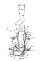
- FIG. 2 is a rear perspective view of the surgical boot of FIG. 1 showing that the surgical boot includes a tensioner unit coupled to a back side of the shell for tightening a patient's foot with the shell by pulling a main strap assembly down toward the shell as shown in FIG. 6 ;
- FIG. 3 is an exploded front perspective view of the surgical boot of FIGS. 1 and 2 showing that the surgical boot includes a toe strap assembly that extends over a patient's foot near a toe end of the shell, the main strap assembly that extends over a patient's foot near a heel end of the shell, a heel strap assembly that extends around the back side of a patient's foot above a patient's heel bone, and a calf strap assembly that extends over a front side of patient's lower leg;
- FIG. 4 is a front perspective view of the surgical boot of FIG. 1 showing buckles of the toe strap assembly, the main strap assembly, and the calf strap assembly opened so that a patient's foot can be lowered into a channel formed by the shell;
- FIG. 5 is a front perspective view of the surgical boot of FIG. 4 after a patient's foot has been lowered into the channel formed by the shell showing the patient's foot secured to the shell by the toe strap assembly, the main strap assembly, and the calf strap assembly;
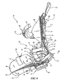
- FIG. 6 is a partially cutaway side elevation view of the surgical boot of FIG. 5 showing the main strap assembly being pulled down toward the shell by the tensioner unit in response to a ratchet being operated by a caregiver;
- FIG. 7 is a partially cutaway side elevation view of the surgical boot of FIG. 6 showing the main strap assembly being loosened when the tensioner unit is disengaged in response to a release lever being operated by a caregiver;
- FIG. 8 is a partially cutaway bottom perspective view of the surgical boot of FIG. 1 showing that the surgical boot includes a strap guide assembly coupled to the bottom of the surgical boot and configured to direct a left strap and a right strap of the main strap assembly from the sides of the surgical boot back toward the heel end of the surgical boot;
- FIG. 9 is a partially diagrammatic view of a surgical table with a pair of couplers each secured to a surgical boot suggesting that the surgical boot is configured for use in a surgical setting and adapted to be supported by a surgical table;
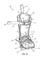
- FIG. 10 is a front perspective view of another surgical boot similar to the surgical boot of FIG. 1 showing that the surgical boot includes a shell without handles, several straps for securing a patient's foot and lower leg to the shell, and a receiver coupled to the bottom of the shell; and
- FIG. 11 is a rear perspective view of the surgical boot of FIG. 10 showing that the surgical boot includes a tensioner unit coupled to a back side of the shell for tightening a patient's foot with the shell by pulling a main strap assembly down toward the shell.
- a surgical foot support is embodied as a surgical boot 10 including a shell 12 providing support structure for the surgical boot 10, a securing system 14, a quick disconnect receiver 15 coupled to shell 12, and a tightener system 50 for tightening and retaining a patient's foot in surgical boot 10 as shown in FIG. 6 .
- Shell 12 includes a main body 16 and a plurality of handles 18, 20, 22, 24 sized and arranged for gripping by a caregiver during surgery to reposition a patient's foot and/or leg, for example when a caregiver is distracting a patient's hip joint or performing surgery on the patient's leg as shown in FIG. 1 .
- Securing system 14 is configured to couple a patient's foot and lower leg to shell 12 of the surgical boot 10 as shown in FIG. 5 .
- Quick disconnect receiver 15 is configured to couple surgical boot 10 to another surgical support as shown diagrammatically in FIG. 9 .
- Tightener system 50 is configured to tighten a patient's foot with shell 12 and to retain a patient's foot in surgical boot 10 during repositioning of a patient's foot as shown in FIG. 6 .
- Shell 12 includes a sole 25 configured to underlie a patient's foot and a calf support 26 configured to support the lower leg of a patient as suggested in FIG. 1 .
- Shell 12 has a toe end 28, a heel end 30, a left side 32, and a right side 34.
- Main body 16 of shell 12 forms an upwardly-facing channel 36 that opens along sole 25 as shown, for example, in FIG. 1 .
- a patient's foot may be lowered into upwardly-facing channel 36 of surgical boot 10 without bending the patient's foot relative to the lower leg of the patient as suggested by arrow 36L in FIG. 4 .
- Calf support 26 is coupled to sole 25 and extends up from sole 25 near heel end 30 of shell 12.
- Tightener system 50 includes a main strap assembly 52 configured to extend over a patient's foot in front of the patient's ankle, a tensioner unit 53 coupled to shell 12, a heel strap assembly 54 configured to extend around a back side of a patient's foot above the patient's heel bone, and a strap guide assembly 56 for guiding main strap assembly 52 from the sides 32, 34 of shell 12 to the heel end 30 of shell 12 as shown in FIG. 6 .
- Main strap assembly 52 is configured to be pulled down toward sole 25 of shell 12 to tighten a patient's foot with shell 12 as suggested by arrow 52T in FIG. 6 .
- Tensioner unit 53 is configured to be operated by a caregiver to pull main strap assembly 52 over a patient's foot down toward sole 25 of shell 12 as shown in FIG.
- Heel strap assembly 54 is coupled to main strap assembly 52 and blocks a patient's heel from lifting up from sole 25 when a caregiver is repositioning a patient foot so that the patient's foot is retained in surgical boot 10.
- Strap guide assembly 56 cooperates with a rear guide beam 110 included in shell 12 to guide main strap assembly 52 from over a patient's foot to the tensioner unit 53.
- Main strap assembly 52 includes a left strap 55, a right strap 57, a foot pad 101, and a buckle 59 for securing left strap 55 to right strap 57 of main strap assembly 52 over a patient's foot as shown in FIG. 3 .
- Buckle 59 is movable between an open configuration allowing a patient's foot to be lowered into channel 36 of surgical boot 10, as shown in FIG. 4 , and a closed configuration blocking a patient's foot from being lifted out of channel 36 of surgical boot 10 as shown in FIG. 5 .
- Foot pad 101 is situated between buckle 59 and a patient's foot when main strap assembly 52 extends over the patient's foot as suggested in FIG. 1 .
- Left strap 55 and right strap 57 of main strap assembly 52 extend through left side 32 and right side 34 of surgical boot 10, respectively, and are both secured to toothed belt 58 by a fastener 61 as shown in FIGS. 2 and 3 .
- Tensioner unit 53 is illustratively coupled along heel end, or back side, 30 of calf support 26 and includes a toothed belt 58, a ratchet 60, and a locator handle 103 as shown, for example, in FIG. 3 . In other embodiments, tensioner unit 53 may be coupled to a bottom side 39 of sole 25. Toothed belt 58 is coupled to main strap assembly 52 by a fastener 61 as shown in FIG. 3 .
- Ratchet 60 is coupled to calf support 26 of shell 12 and is configured to advance toothed belt 58 in a forward direction indicated by an arrow 58F in FIG. 6 to pull main strap assembly 52 down toward sole 25 of shell 12.
- Locator handle 103 is coupled to ratchet 60 and is configured to hang down from ratchet 60 so that a caregiver can tactilely locate and/or operate ratchet 60 during a surgery.
- other tightening devices such as reels, worm gears, gear sets, or motors may be used to pull main strap assembly 52.
- Ratchet 60 illustratively includes an actuator handle 31, a keeper pawl 33, and a release lever 35 as shown, for example, in FIG. 6 .
- Actuator handle 31 includes an actuator lever 37 and a ratchet pawl 39.
- Actuator handle 31 is illustratively operated by a caregiver pivoting actuator lever 37 as suggested by arrow 31 A in FIG. 6 so that ratchet pawl 39 advances toothed belt 58 through ratchet 60.
- Keeper pawl 33 is configured to block toothed belt 58 from moving backward through ratchet 60 while actuator handle 31 advances toothed belt 58.
- Release lever 35 is configured to be operated by a caregiver pivoting release lever 35, as suggested by arrow 35A in FIG.
- Heel strap assembly 54 includes a strap 106 and a heel pad 108 as shown in FIG. 3 .
- Strap 106 is slidably coupled at a first end 105 to left strap 55 of main strap assembly 52 and at a second end 107 to right strap 57 of main strap assembly 52 as suggested in FIG. 3 .
- Heel pad 108 is situated between strap 106 and a patient's heel to cushion the patient's heel as suggested in FIG. 2 .
- main strap assembly 52 and heel strap assembly 54 cooperate to extend around a patient's ankle and to retain a patient's heel in surgical boot 10 during repositioning of the patient's foot by a caregiver.
- Strap guide assembly 56 receives left and right straps 55, 57 of main strap assembly 52 from left and right sides 32, 34 of shell 12 and redirects left and right straps 55, 57 out from strap guide assembly 56 toward heel end 30 of shell 12 as shown in FIG. 8 .
- Strap guide assembly 56 is coupled to sole 25 of shell 12 between sole 25 and quick disconnect receiver 1.
- Strap guide assembly 56 includes a top plate 63, a bottom plate 65, a top guide pin 67, and a bottom guide pin 69.
- Top guide pin 67 is supported by top plate 63 and engages right strap 57 of main strap assembly 52 to direct right strap 57 from the right side 34 of shell 12 back toward heel end 30 of shell 12 as shown in FIG. 8 .
- Bottom guide pin 69 is supported by bottom plate 65 and engages left strap 55 of main strap assembly 52 to direct left strap 55 from the left side 32 of shell 12 back toward heel end 30 of shell 12.
- Guide pins 67, 69 are oriented to form an X-shape with each guide pin 67, 69 angled about forty-five degrees from an axis extending from the toe end 28 to the heel end 30 of shell 12.
- Top plate 63 is coupled to bottom plate 65 by fasteners 86, as shown in FIG. 3 .
- Rear guide beam 110 included in shell 12 forms heel end 30 of shell 12 arranged behind the calf support 26 as shown in FIG. 6 .
- Calf support 26 of shell 12 is formed to include a channel 112 for guiding left and right straps 55, 57 of main strap assembly 52 and toothed belt 58 along calf support 26 as shown in FIG. 2 .
- Rear guide beam 110 directs main strap assembly 52 from heel end 30 of shell 12 up along channel 112 formed in calf support 26.
- Rear guide beam 110 includes a pair of beam guide pins 114 as shown in FIGS. 3 and 6 for engaging and directing left and right straps 55, 57 of main strap assembly 52.
- Surgical boot 10 also includes a channel guide pin 118 as shown in FIGS. 2 and 3 for holding left and right straps 55, 57 of main strap assembly 52 in position relative to channel 112 along calf support 26.
- Plurality of handles 18, 20, 22, 24 is made up of lower left handle 18, lower right handle 20, upper left handle 22, and upper right handle 24 as shown in FIG. 1 .
- shell 12 is made from a monolithic plastics material and thus each of the plurality of handles 18, 20, 22, 24 is integrally formed with main body 16 of shell 12.
- shell 12 may be made from an ABS polycarbonate blended material.
- the plurality of handles 18, 20, 22, 24 have a thickness similar to a thickness of main body 16 as shown in FIG. 1 .
- the handles 18, 20, 22, 24 and the main body 16 have a thickness of about 0.2 inches. In other embodiments, other thicknesses of shell 12 may be used.
- Lower left handle 18 and lower right handle 20 extend from calf support 26 near heel end 30 of shell 12 to sole 25 near toe end 28 of shell 12 so that lower left and lower right handles 18, 20 are arranged to extend along the length of a patient's foot as suggested in FIG. 2 .
- Lower left handle 18 and lower right handle 20 form corresponding lower handhold openings 18H, 20H that extend through shell 12.
- Lower handhold openings 18H, 20H are sized to allow a caregiver's hand to pass through shell 12.
- Lower left handle 18 and lower right handle 20 are arcuate and extend away from channel 36 of main body 16 along left side 32 of shell 12 and right side 34 of shell 12, respectively, so that a caregiver can grip lower left handle 18 and lower right handle 20 with a portion of his hand situated between a patient's foot and shell 12.
- Upper left handle 22 and upper right handle 24 are arcuate and extend away from channel 36 along calf support 26 from a top end 37 of calf support 26 down toward sole 25 of shell 12 so that upper left and upper right handles 22, 24 are arranged to extend along the length of a patient's lower leg as suggested in FIG. 1 .
- Upper left handle 22 and upper right handle 24 form corresponding handhold openings 22H and 24H that extend through shell 12.
- Upper handhold openings 22H, 24H are sized to allow a caregiver's hand to pass through shell 12.
- Upper left handle 22 and upper right handle 24 are arcuate and extend away from channel 36 of main body 16 along left side 32 of shell 12 and right side 34 of shell 12, respectively, so that a caregiver can grip upper left handle 22 and upper right handle 24 with a portion of his hand situated between a patient's lower leg and shell 12.
- Securing system 14 is configured to couple a patient's foot and lower leg to shell 12 of the surgical boot 10 and includes a foot securing system 38 and a calf securing system 40 as shown in FIG. 1 .
- Foot securing system 38 is configured to couple a patient's foot to sole 25 of shell 12 and illustratively includes a toe strap assembly 42 and a sole pad 44 as shown in FIGS. 1 and 3 .
- Sole pad 44 is coupled to sole 25 of shell 12 to cushion a patient's foot when a patient is secured to surgical boot 10 as suggested in FIG. 1 .
- Calf securing system 40 is configured to couple a patient's lower leg to calf support 26 of shell 12 and illustratively includes leg strap assembly 46 and a calf pad 48 as shown in FIGS. 1 and 3 .
- Calf pad 48 is coupled to calf support 26 of shell 12 to cushion a patient's lower leg when a patient is secured to surgical boot 10 as suggested in FIG. 1 .
- Quick disconnect receiver 15 is illustratively coupled to a bottom side 39 of sole 25 and extends downwardly from sole 25 as shown in FIG. 2 .
- Quick disconnect receiver 15 is configured to couple to a coupler 41 attached to a surgical table 43 as shown diagrammatically in FIG. 4 .
- quick disconnect receiver 15 includes a receiver body 45, a release handle 47, and a retainer lug 49 as shown, for example, in FIG. 3 .
- Retainer lug 49 is configured to engage coupler 41 when quick disconnect receiver 15 is coupled to coupler 41.
- Release handle 47 is configured to disengage retainer lug 49 from coupler 41 so that surgical boot 10 can be moved away from coupler 41.
- Coupler 41 may include one or more of a handle, a post, a spar, a clamp, and a carriage as is known in the art.
- quick disconnect receiver 15 may be movably coupled to coupler 41 so that a caregiver can position surgical boot 10 at different positions along coupler 41.
- quick disconnect receiver 15 may be configured to couple directly to surgical table 43. Quick disconnect receiver 15 allows surgical boot 10 to be positioned for surgery, traction, and other applications of the surgical boot 10.
- Calf support 26 includes a left leg 62, a right leg 64, and a calf plate 66 supported near heel end 30 of shell 12 as shown in FIG. 2 .
- Left leg 62 and right leg 64 extend up from sole 25 along left and right sides 32, 34 of shell 12 and support calf plate 66.
- Left leg 62, right leg 64, and calf plate 66 cooperate to form an opening 68 between sole 25 and calf plate 66 near heel end 30 of shell 12.
- Toe strap assembly 42 of foot securing system 38 is configured to extend across a patient's foot near the toe end 28 shell 12 when a patient is secured to surgical boot 10 as shown, for example, in FIG. 5 .
- Toe strap assembly 42 includes a left strap 70, a right strap 72, a buckle 74, and a toe pad 76 as shown in FIG. 3 .
- Left strap 70 of toe strap assembly 42 has a first end 78 coupled to left side 32 of shell 12 by a fastener 79 and a second end 80.
- Right strap 72 of toe strap assembly 42 has a first end 82 coupled to right side 34 of shell 12 by a fastener 83 and a second end 84 coupled to buckle 74.
- Buckle 74 of toe strap assembly 42 is configured to move between an open configuration allowing a patient's foot from being lifted out of channel 36 of surgical boot 10 and a closed configuration blocking a patient from lifting his foot out of channel 36.
- Buckle 74 is slidably coupled to left strap 70 so that toe strap assembly 42 may be tightened or loosened over a patient's foot by a caregiver.
- Toe pad 76 is situated between buckle 74 and a patient's foot to cushion a patient's foot when toe strap assembly 42 extends over a patient's foot as shown in FIG. 1 .
- Leg strap assembly 46 of calf securing system 40 is configured to extend over a patient's lower leg near the top end 37 of calf support 26 when a patient is secured to surgical boot 10 as suggested in FIG. 5 .
- Leg strap assembly 46 includes a left strap 90, a right strap 92, a buckle 94, and a leg pad 96 as shown, for example, in FIG. 3 .
- Left strap 90 of leg strap assembly 46 has a first end 98 coupled to calf plate 66 by a fastener 99 and a second end 100.
- Right strap 92 of leg strap assembly 46 has a first end 102 coupled to calf plate 66 by a fastener 105 and a second end 104.
- Buckle 94 of leg strap assembly 46 is configured to move between an open configuration allowing a patient's lower leg to be lowered into channel 36 of surgical boot 10 and a closed configuration blocking a patient's lower leg from being lifted out of channel 36 of surgical boot 10.
- Buckle 94 is slidably coupled to left strap 90 so that leg strap assembly 46 may be tightened or loosened over a patient's lower leg by a caregiver.
- Leg pad 96 is situated between buckle 94 and the patient's lower leg to cushion a patient's lower leg when leg strap assembly 46 extends over a patient's lower leg as shown in FIG. 1 .
- a caregiver moves buckle 59 of main strap assembly 52, buckle 74 of toe strap assembly 42, and buckle 94 of leg strap assembly 46 to the open position to allow a patient's foot to be lowered into channel 36 of surgical boot 10 as shown in FIG. 4 .
- a caregiver places a patient's foot into channel 36 of surgical boot 10.
- a caregiver guides straps included in toe strap assembly 42, leg strap assembly 46, main strap assembly 52, and heel strap assembly 54 over a patient's foot and lower leg.
- a caregiver moves buckle 59 of main strap assembly 52, buckle 74 of toe strap assembly 42, and buckle 94 of leg strap assembly 46 to the closed position to block the patient's foot from being removed from surgical boot 10 as shown in FIG. 5 .
- the caregiver operates ratchet 60 of tensioner unit 53 to advance toothed belt 58 through ratchet 60 thereby pulling main strap assembly 52 down over a patient's foot so that a patient's foot is tightened with shell 12 of surgical boot 10.
- the caregiver may then couple quick disconnect receiver 15 with coupler 41 to support surgical boot 10 at a location or for movement along coupler 41.
- a caregiver may then manipulate the position or arrangement of the patient by gripping one or more of the plurality of handles 18, 20, 22, 24.
- heel strap 54 is configured to engage the back side of a patient's foot above the heel bone to hold the patient's heel in contact with shell 12 of surgical boot 10 resisting movement of the patient's foot relative to shell 12.
- FIGS. 11 and 12 Another surgical boot 210 is shown in FIGS. 11 and 12.
- Surgical boot 210 is similar to surgical boot 10 shown in FIGS. 1-10 and like reference numerals are used to denote similar parts.
- surgical boot 210 includes a shell 212 formed to include a sole 225 and a calf support 226 without handles as shown in FIGS. 11 and 12 thereby leaving the sides of shell 212 open so that a caregiver can access a patient's foot or lower leg from the side.
- surgical boot 210 may be used with other surgical supports including mechanical devices for moving surgical boot 210 in order to distract a patient's hip joint or perform surgery on the patient's leg.
Landscapes
- Health & Medical Sciences (AREA)
- Engineering & Computer Science (AREA)
- Biomedical Technology (AREA)
- Life Sciences & Earth Sciences (AREA)
- Animal Behavior & Ethology (AREA)
- General Health & Medical Sciences (AREA)
- Public Health (AREA)
- Veterinary Medicine (AREA)
- Accommodation For Nursing Or Treatment Tables (AREA)
- Orthopedics, Nursing, And Contraception (AREA)
Description
- The present disclosure relates to a patient support apparatus for supporting a patient during surgery. More particularly, the present disclosure relates to a surgical boot for supporting a patient during surgery.
- Often, when a patient is sedated for a surgery, the patient is supported by and secured to braces or supports coupled to a surgical table. Sometimes, unique supports are provided for a patient's extremities such as arm boards, leg supports, hand boards, stirrups, and boots.
- Supports known in the art sometimes secure patients to resist patient movement. Such supports can sometimes allow excessive patient movement relative to the supports.
-
WO 2008/133970 provides an orthopedic shoe allowing access to the plantar surface of a patient's foot. The shoe has a retaining strap for retaining a patient's foot within the shoe that is engaged with a tightening knob on the side of the shoe. The tightening knob may be rotated to tighten or loosen the retaining strap. DocumentUS 2004 133 979 discloses a surgical boot for supporting a patient during surgery comprising all the features of the preamble of claim 1. - A surgical boot has one or more of the following features, alone or in any combination, according to the claims
- A surgical boot for supporting a patient during surgery as claimed in claim 1 is disclosed and includes a shell shaped to receive a patient's foot and a main strap assembly. The main strap assembly includes at least one strap that secures a patient's foot in the shell and that is pulled downwardly by a tensioner unit located behind the shell to tighten a patient's foot with the shell. The at least one strap extends across an upwardly-facing channel formed by the shell and through a left side and a right side of the shell.
- In some embodiments, the tensioner unit may include a ratchet and a toothed belt coupled to the at least one strap. The toothed belt may be advanced in a forward direction through the ratchet to pull the at least one strap of the main strap assembly. The ratchet may include an actuator lever operable by a caregiver to advance the toothed belt through the ratchet and a release lever configured to selectively release the toothed belt from the ratchet so that the toothed belt is free to move in a backward direction through the ratchet. The ratchet may include a ratchet pawl engaging the toothed belt to advance the toothed belt in a forward direction and a keeper pawl configured to engage the toothed belt and block the toothed belt from moving in the backward direction.
- The surgical boot may include a strap guide assembly configured to guide a first strap and a second strap included in the main strap assembly from left and right sides of the shell toward a heel end of the shell. The shell may include a sole and the strap guide assembly may be coupled to a bottom side of the sole.
- It is contemplated that the shell may have a toe end and a heel end. The shell may include a sole, a calf support extending up from the sole near the heel end of the shell, and a rear guide beam situated behind the calf support and forming the heel end of the shell. The rear guide beam may be configured to guide a first strap and a second strap included in the main strap assembly from below the sole toward the calf support. The calf support may be formed to include a guide channel configured to receive and guide the first strap and the second strap along the calf support.
- The surgical boot may include a heel strap assembly configured to extend around the back side of a patient's foot over a patient's heel bone. The heel strap assembly may have a first end coupled to the main strap assembly and a second end coupled to the main strap assembly. The heel strap assembly may be configured to extend around the back side of a patient's foot above a patient's heel bone.
- The tensioner unit may be coupled to the shell and may be configured to pull the main strap assembly toward the sole of the shell to tighten a patient's foot with the shell.
- The main strap assembly may include a left strap and a right strap.
- The tensioner unit may include a ratchet and a toothed belt coupled to the left strap and the right strap. The left strap and the right strap may extend through the shell.
- The first end and the second end of the heel strap assembly may be slidably coupled to the main strap assembly. In some embodiments, the surgical boot may include a receiver configured to couple the surgical boot to a surgical table.
- The invention will now be further described by way of example with reference to the accompanying drawings, in which:
-
FIG. 1 is a front perspective view of a surgical boot including a shell sized to receive a patient's foot and formed to include handles for use by a caregiver, several straps for securing a patient's foot and lower leg to the shell as shown inFIG. 5 , and a receiver coupled to the bottom of the shell for connecting the surgical boot to a surgical table as shown inFIG. 9 ; -
FIG. 2 is a rear perspective view of the surgical boot ofFIG. 1 showing that the surgical boot includes a tensioner unit coupled to a back side of the shell for tightening a patient's foot with the shell by pulling a main strap assembly down toward the shell as shown inFIG. 6 ; -
FIG. 3 is an exploded front perspective view of the surgical boot ofFIGS. 1 and2 showing that the surgical boot includes a toe strap assembly that extends over a patient's foot near a toe end of the shell, the main strap assembly that extends over a patient's foot near a heel end of the shell, a heel strap assembly that extends around the back side of a patient's foot above a patient's heel bone, and a calf strap assembly that extends over a front side of patient's lower leg; -
FIG. 4 is a front perspective view of the surgical boot ofFIG. 1 showing buckles of the toe strap assembly, the main strap assembly, and the calf strap assembly opened so that a patient's foot can be lowered into a channel formed by the shell; -
FIG. 5 is a front perspective view of the surgical boot ofFIG. 4 after a patient's foot has been lowered into the channel formed by the shell showing the patient's foot secured to the shell by the toe strap assembly, the main strap assembly, and the calf strap assembly; -
FIG. 6 is a partially cutaway side elevation view of the surgical boot ofFIG. 5 showing the main strap assembly being pulled down toward the shell by the tensioner unit in response to a ratchet being operated by a caregiver; -
FIG. 7 is a partially cutaway side elevation view of the surgical boot ofFIG. 6 showing the main strap assembly being loosened when the tensioner unit is disengaged in response to a release lever being operated by a caregiver; -
FIG. 8 is a partially cutaway bottom perspective view of the surgical boot ofFIG. 1 showing that the surgical boot includes a strap guide assembly coupled to the bottom of the surgical boot and configured to direct a left strap and a right strap of the main strap assembly from the sides of the surgical boot back toward the heel end of the surgical boot; -
FIG. 9 is a partially diagrammatic view of a surgical table with a pair of couplers each secured to a surgical boot suggesting that the surgical boot is configured for use in a surgical setting and adapted to be supported by a surgical table; -
FIG. 10 is a front perspective view of another surgical boot similar to the surgical boot ofFIG. 1 showing that the surgical boot includes a shell without handles, several straps for securing a patient's foot and lower leg to the shell, and a receiver coupled to the bottom of the shell; and -
FIG. 11 is a rear perspective view of the surgical boot ofFIG. 10 showing that the surgical boot includes a tensioner unit coupled to a back side of the shell for tightening a patient's foot with the shell by pulling a main strap assembly down toward the shell. - In one illustrative embodiment, a surgical foot support is embodied as a
surgical boot 10 including ashell 12 providing support structure for thesurgical boot 10, asecuring system 14, aquick disconnect receiver 15 coupled toshell 12, and atightener system 50 for tightening and retaining a patient's foot insurgical boot 10 as shown inFIG. 6 .Shell 12 includes a main body 16 and a plurality ofhandles FIG. 1 . Securingsystem 14 is configured to couple a patient's foot and lower leg toshell 12 of thesurgical boot 10 as shown inFIG. 5 .Quick disconnect receiver 15 is configured to couplesurgical boot 10 to another surgical support as shown diagrammatically inFIG. 9 .Tightener system 50 is configured to tighten a patient's foot withshell 12 and to retain a patient's foot insurgical boot 10 during repositioning of a patient's foot as shown inFIG. 6 . -
Shell 12 includes a sole 25 configured to underlie a patient's foot and acalf support 26 configured to support the lower leg of a patient as suggested inFIG. 1 . Shell 12 has atoe end 28, aheel end 30, aleft side 32, and aright side 34. Main body 16 ofshell 12 forms an upwardly-facingchannel 36 that opens along sole 25 as shown, for example, inFIG. 1 . A patient's foot may be lowered into upwardly-facingchannel 36 ofsurgical boot 10 without bending the patient's foot relative to the lower leg of the patient as suggested by arrow 36L inFIG. 4 .Calf support 26 is coupled to sole 25 and extends up from sole 25 nearheel end 30 ofshell 12. -
Tightener system 50 includes amain strap assembly 52 configured to extend over a patient's foot in front of the patient's ankle, atensioner unit 53 coupled toshell 12, aheel strap assembly 54 configured to extend around a back side of a patient's foot above the patient's heel bone, and astrap guide assembly 56 for guidingmain strap assembly 52 from thesides shell 12 to theheel end 30 ofshell 12 as shown inFIG. 6 .Main strap assembly 52 is configured to be pulled down toward sole 25 ofshell 12 to tighten a patient's foot withshell 12 as suggested byarrow 52T inFIG. 6 .Tensioner unit 53 is configured to be operated by a caregiver to pullmain strap assembly 52 over a patient's foot down toward sole 25 ofshell 12 as shown inFIG. 6 .Heel strap assembly 54 is coupled tomain strap assembly 52 and blocks a patient's heel from lifting up from sole 25 when a caregiver is repositioning a patient foot so that the patient's foot is retained insurgical boot 10.Strap guide assembly 56 cooperates with arear guide beam 110 included inshell 12 to guidemain strap assembly 52 from over a patient's foot to thetensioner unit 53. -
Main strap assembly 52 includes aleft strap 55, aright strap 57, afoot pad 101, and abuckle 59 for securingleft strap 55 toright strap 57 ofmain strap assembly 52 over a patient's foot as shown inFIG. 3 .Buckle 59 is movable between an open configuration allowing a patient's foot to be lowered intochannel 36 ofsurgical boot 10, as shown inFIG. 4 , and a closed configuration blocking a patient's foot from being lifted out ofchannel 36 ofsurgical boot 10 as shown inFIG. 5 .Foot pad 101 is situated betweenbuckle 59 and a patient's foot whenmain strap assembly 52 extends over the patient's foot as suggested inFIG. 1 .Left strap 55 andright strap 57 ofmain strap assembly 52 extend throughleft side 32 andright side 34 ofsurgical boot 10, respectively, and are both secured totoothed belt 58 by afastener 61 as shown inFIGS. 2 and3 . -
Tensioner unit 53 is illustratively coupled along heel end, or back side, 30 ofcalf support 26 and includes atoothed belt 58, aratchet 60, and alocator handle 103 as shown, for example, inFIG. 3 . In other embodiments,tensioner unit 53 may be coupled to abottom side 39 of sole 25.Toothed belt 58 is coupled tomain strap assembly 52 by afastener 61 as shown inFIG. 3 .Ratchet 60 is coupled tocalf support 26 ofshell 12 and is configured to advancetoothed belt 58 in a forward direction indicated by anarrow 58F inFIG. 6 to pullmain strap assembly 52 down toward sole 25 ofshell 12. Locator handle 103 is coupled to ratchet 60 and is configured to hang down fromratchet 60 so that a caregiver can tactilely locate and/or operateratchet 60 during a surgery. In other embodiments, other tightening devices such as reels, worm gears, gear sets, or motors may be used to pullmain strap assembly 52. -
Ratchet 60 illustratively includes anactuator handle 31, akeeper pawl 33, and arelease lever 35 as shown, for example, inFIG. 6 . Actuator handle 31 includes anactuator lever 37 and aratchet pawl 39. Actuator handle 31 is illustratively operated by a caregiver pivotingactuator lever 37 as suggested byarrow 31 A inFIG. 6 so thatratchet pawl 39 advancestoothed belt 58 throughratchet 60.Keeper pawl 33 is configured to blocktoothed belt 58 from moving backward throughratchet 60 while actuator handle 31 advancestoothed belt 58.Release lever 35 is configured to be operated by a caregiver pivotingrelease lever 35, as suggested byarrow 35A inFIG. 7 , so thatkeeper pawl 33 and ratchetpawl 39 are moved out of engagement withtoothed belt 58 thereby allowingtoothed belt 58 to move backward throughratchet 60 as suggested byarrow 58B inFIG. 7 . - Heel
strap assembly 54 includes astrap 106 and aheel pad 108 as shown inFIG. 3 .Strap 106 is slidably coupled at afirst end 105 to leftstrap 55 ofmain strap assembly 52 and at asecond end 107 toright strap 57 ofmain strap assembly 52 as suggested inFIG. 3 .Heel pad 108 is situated betweenstrap 106 and a patient's heel to cushion the patient's heel as suggested inFIG. 2 . When a patient's foot is secured insurgical boot 10,main strap assembly 52 andheel strap assembly 54 cooperate to extend around a patient's ankle and to retain a patient's heel insurgical boot 10 during repositioning of the patient's foot by a caregiver. -
Strap guide assembly 56 receives left andright straps main strap assembly 52 from left andright sides shell 12 and redirects left andright straps strap guide assembly 56 towardheel end 30 ofshell 12 as shown inFIG. 8 .Strap guide assembly 56 is coupled to sole 25 ofshell 12 between sole 25 and quick disconnect receiver 1.Strap guide assembly 56 includes atop plate 63, abottom plate 65, atop guide pin 67, and abottom guide pin 69. -
Top guide pin 67 is supported bytop plate 63 and engagesright strap 57 ofmain strap assembly 52 to directright strap 57 from theright side 34 ofshell 12 back towardheel end 30 ofshell 12 as shown inFIG. 8 .Bottom guide pin 69 is supported bybottom plate 65 and engages leftstrap 55 ofmain strap assembly 52 to directleft strap 55 from theleft side 32 ofshell 12 back towardheel end 30 ofshell 12. Guide pins 67, 69 are oriented to form an X-shape with eachguide pin toe end 28 to theheel end 30 ofshell 12.Top plate 63 is coupled tobottom plate 65 byfasteners 86, as shown inFIG. 3 . -
Rear guide beam 110 included inshell 12forms heel end 30 ofshell 12 arranged behind thecalf support 26 as shown inFIG. 6 .Calf support 26 ofshell 12 is formed to include achannel 112 for guiding left andright straps main strap assembly 52 andtoothed belt 58 alongcalf support 26 as shown inFIG. 2 .Rear guide beam 110 directsmain strap assembly 52 fromheel end 30 ofshell 12 up alongchannel 112 formed incalf support 26.Rear guide beam 110 includes a pair of beam guide pins 114 as shown inFIGS. 3 and6 for engaging and directing left andright straps main strap assembly 52.Surgical boot 10 also includes achannel guide pin 118 as shown inFIGS. 2 and3 for holding left andright straps main strap assembly 52 in position relative to channel 112 alongcalf support 26. - Plurality of
handles left handle 18, lowerright handle 20, upperleft handle 22, and upperright handle 24 as shown inFIG. 1 . In the illustrative embodiment,shell 12 is made from a monolithic plastics material and thus each of the plurality ofhandles shell 12. Illustratively,shell 12 may be made from an ABS polycarbonate blended material. Further, the plurality ofhandles FIG. 1 . Illustratively, thehandles shell 12 may be used. - Lower left
handle 18 and lowerright handle 20 extend fromcalf support 26 nearheel end 30 ofshell 12 to sole 25 neartoe end 28 ofshell 12 so that lower left and lower right handles 18, 20 are arranged to extend along the length of a patient's foot as suggested inFIG. 2 . Lower lefthandle 18 and lowerright handle 20 form correspondinglower handhold openings shell 12.Lower handhold openings shell 12. Lower lefthandle 18 and lowerright handle 20 are arcuate and extend away fromchannel 36 of main body 16 alongleft side 32 ofshell 12 andright side 34 ofshell 12, respectively, so that a caregiver can grip lower lefthandle 18 and lowerright handle 20 with a portion of his hand situated between a patient's foot andshell 12. - Upper left
handle 22 and upperright handle 24 are arcuate and extend away fromchannel 36 alongcalf support 26 from atop end 37 ofcalf support 26 down toward sole 25 ofshell 12 so that upper left and upper right handles 22, 24 are arranged to extend along the length of a patient's lower leg as suggested inFIG. 1 . Upper lefthandle 22 and upperright handle 24 form correspondinghandhold openings shell 12.Upper handhold openings shell 12. Upper lefthandle 22 and upperright handle 24 are arcuate and extend away fromchannel 36 of main body 16 alongleft side 32 ofshell 12 andright side 34 ofshell 12, respectively, so that a caregiver can grip upperleft handle 22 and upper right handle 24 with a portion of his hand situated between a patient's lower leg andshell 12. - Securing
system 14 is configured to couple a patient's foot and lower leg to shell 12 of thesurgical boot 10 and includes afoot securing system 38 and acalf securing system 40 as shown inFIG. 1 . Foot securingsystem 38 is configured to couple a patient's foot to sole 25 ofshell 12 and illustratively includes atoe strap assembly 42 and asole pad 44 as shown inFIGS. 1 and3 .Sole pad 44 is coupled to sole 25 ofshell 12 to cushion a patient's foot when a patient is secured tosurgical boot 10 as suggested inFIG. 1 .Calf securing system 40 is configured to couple a patient's lower leg tocalf support 26 ofshell 12 and illustratively includesleg strap assembly 46 and acalf pad 48 as shown inFIGS. 1 and3 .Calf pad 48 is coupled tocalf support 26 ofshell 12 to cushion a patient's lower leg when a patient is secured tosurgical boot 10 as suggested inFIG. 1 . -
Quick disconnect receiver 15 is illustratively coupled to abottom side 39 of sole 25 and extends downwardly from sole 25 as shown inFIG. 2 .Quick disconnect receiver 15 is configured to couple to acoupler 41 attached to a surgical table 43 as shown diagrammatically inFIG. 4 . In the illustrative embodiment,quick disconnect receiver 15 includes areceiver body 45, arelease handle 47, and aretainer lug 49 as shown, for example, inFIG. 3 .Retainer lug 49 is configured to engagecoupler 41 whenquick disconnect receiver 15 is coupled tocoupler 41. Release handle 47 is configured to disengageretainer lug 49 fromcoupler 41 so thatsurgical boot 10 can be moved away fromcoupler 41. -
Coupler 41 may include one or more of a handle, a post, a spar, a clamp, and a carriage as is known in the art. In some embodiments,quick disconnect receiver 15 may be movably coupled tocoupler 41 so that a caregiver can positionsurgical boot 10 at different positions alongcoupler 41. In some embodiments,quick disconnect receiver 15 may be configured to couple directly to surgical table 43.Quick disconnect receiver 15 allowssurgical boot 10 to be positioned for surgery, traction, and other applications of thesurgical boot 10. -
Calf support 26 includes aleft leg 62, aright leg 64, and a calf plate 66 supported nearheel end 30 ofshell 12 as shown inFIG. 2 .Left leg 62 andright leg 64 extend up from sole 25 along left andright sides shell 12 and support calf plate 66.Left leg 62,right leg 64, and calf plate 66 cooperate to form anopening 68 between sole 25 and calf plate 66 nearheel end 30 ofshell 12. -
Toe strap assembly 42 offoot securing system 38 is configured to extend across a patient's foot near thetoe end 28shell 12 when a patient is secured tosurgical boot 10 as shown, for example, inFIG. 5 .Toe strap assembly 42 includes aleft strap 70, aright strap 72, abuckle 74, and atoe pad 76 as shown inFIG. 3 .Left strap 70 oftoe strap assembly 42 has afirst end 78 coupled toleft side 32 ofshell 12 by afastener 79 and asecond end 80.Right strap 72 oftoe strap assembly 42 has afirst end 82 coupled toright side 34 ofshell 12 by afastener 83 and asecond end 84 coupled to buckle 74.Buckle 74 oftoe strap assembly 42 is configured to move between an open configuration allowing a patient's foot from being lifted out ofchannel 36 ofsurgical boot 10 and a closed configuration blocking a patient from lifting his foot out ofchannel 36.Buckle 74 is slidably coupled toleft strap 70 so thattoe strap assembly 42 may be tightened or loosened over a patient's foot by a caregiver.Toe pad 76 is situated betweenbuckle 74 and a patient's foot to cushion a patient's foot whentoe strap assembly 42 extends over a patient's foot as shown inFIG. 1 . -
Leg strap assembly 46 ofcalf securing system 40 is configured to extend over a patient's lower leg near thetop end 37 ofcalf support 26 when a patient is secured tosurgical boot 10 as suggested inFIG. 5 .Leg strap assembly 46 includes aleft strap 90, aright strap 92, abuckle 94, and aleg pad 96 as shown, for example, inFIG. 3 .Left strap 90 ofleg strap assembly 46 has afirst end 98 coupled to calf plate 66 by afastener 99 and asecond end 100.Right strap 92 ofleg strap assembly 46 has afirst end 102 coupled to calf plate 66 by afastener 105 and asecond end 104.Buckle 94 ofleg strap assembly 46 is configured to move between an open configuration allowing a patient's lower leg to be lowered intochannel 36 ofsurgical boot 10 and a closed configuration blocking a patient's lower leg from being lifted out ofchannel 36 ofsurgical boot 10.Buckle 94 is slidably coupled toleft strap 90 so thatleg strap assembly 46 may be tightened or loosened over a patient's lower leg by a caregiver.Leg pad 96 is situated betweenbuckle 94 and the patient's lower leg to cushion a patient's lower leg whenleg strap assembly 46 extends over a patient's lower leg as shown inFIG. 1 . - In illustrative operation, a caregiver moves
buckle 59 ofmain strap assembly 52, buckle 74 oftoe strap assembly 42, and buckle 94 ofleg strap assembly 46 to the open position to allow a patient's foot to be lowered intochannel 36 ofsurgical boot 10 as shown inFIG. 4 . A caregiver places a patient's foot intochannel 36 ofsurgical boot 10. A caregiver guides straps included intoe strap assembly 42,leg strap assembly 46,main strap assembly 52, andheel strap assembly 54 over a patient's foot and lower leg. A caregiver movesbuckle 59 ofmain strap assembly 52, buckle 74 oftoe strap assembly 42, and buckle 94 ofleg strap assembly 46 to the closed position to block the patient's foot from being removed fromsurgical boot 10 as shown inFIG. 5 . Then the caregiver operates ratchet 60 oftensioner unit 53 to advancetoothed belt 58 throughratchet 60 thereby pullingmain strap assembly 52 down over a patient's foot so that a patient's foot is tightened withshell 12 ofsurgical boot 10. The caregiver may then couplequick disconnect receiver 15 withcoupler 41 to supportsurgical boot 10 at a location or for movement alongcoupler 41. A caregiver may then manipulate the position or arrangement of the patient by gripping one or more of the plurality ofhandles heel strap 54 is configured to engage the back side of a patient's foot above the heel bone to hold the patient's heel in contact withshell 12 ofsurgical boot 10 resisting movement of the patient's foot relative to shell 12. - Another
surgical boot 210 is shown inFIGS. 11 and 12.Surgical boot 210 is similar tosurgical boot 10 shown inFIGS. 1-10 and like reference numerals are used to denote similar parts. However,surgical boot 210 includes ashell 212 formed to include a sole 225 and acalf support 226 without handles as shown inFIGS. 11 and 12 thereby leaving the sides ofshell 212 open so that a caregiver can access a patient's foot or lower leg from the side. In some embodiments,surgical boot 210 may be used with other surgical supports including mechanical devices for movingsurgical boot 210 in order to distract a patient's hip joint or perform surgery on the patient's leg.
Claims (14)
- A surgical boot (10) for supporting a patient during surgery comprising a shell (12) shaped to receive a patient's foot and a main strap assembly (52) including at least one strap that secures a patient's foot in the shell is
characterized in that the at least one strap pulled downwardly by a tensioner unit (53) located behind the shell to tighten a patient's foot with the shell (12),
and the at least one strap extends across an upwardly-facing channel (36) formed by the shell (12) and through a left side and a right side of the shell (12). - The surgical boot (10) of claim 1, wherein the tensioner unit (53) includes a ratchet (60) and a toothed belt (58) coupled to the at least one strap, the toothed belt (58) configured to be advanced in a forward direction through the ratchet (60) to pull the at least one strap of the main strap assembly (52).
- The surgical boot (10) of claim 2, wherein the ratchet (60) includes an actuator lever (37) operable by a caregiver to advance the toothed belt (58) through the ratchet (60) and a release lever (35) configured to selectively release the toothed belt (58) from the ratchet (60) so that the toothed belt (58) is free to move in a backward direction through the ratchet (60), and/ or wherein the ratchet (60) includes a ratchet pawl (39) engaging the toothed belt (58) to advance the toothed belt (58) in a forward direction and a keeper pawl (33) configured to engage the toothed belt (58) and block the toothed belt (58) from moving in the backward direction.
- The surgical boot (10) of claim 1, further comprising a strap guide assembly (56) configured to guide a first strap (55) and a second strap (57) included in the main strap assembly (52) from left and right sides of the shell (12) toward a heel end (30) of the shell (12).
- The surgical boot (10) of claim 4, wherein the shell (12) includes a sole (25) and the strap guide assembly (56) is coupled to a bottom side of the sole (25).
- The surgical boot (10) of any preceding claim, wherein the shell (12) has a toe end (28) and a heel end (30), the shell (12) including a sole (25), a calf support (26) extending up from the sole (25) near the heel end (30) of the shell (12), and a rear guide beam (110) situated behind the calf support (26) and forming the heel end (30) of the shell (12), the rear guide beam (110) configured to guide a first strap (55) and a second strap (57) included in the main strap assembly (52) from below the sole (25) toward the calf support (26).
- The surgical boot (10) of claim 6, wherein the calf support (26) is formed to include a guide channel (112) configured to receive and guide the first strap (55) and the second strap (57) along the calf support (26).
- The surgical boot (10) of any preceding claim, further comprising a heel strap assembly (54) configured to extend around the back side of a patient's foot over a patient's heel bone.
- The surgical boot (10) of claim 8, wherein the heel strap (54) has a first end (105) coupled to the main strap assembly (52) and a second end (107) coupled to the main strap assembly (52).
- The surgical boot (10) of claim 9, wherein the first end (105) and the second end (107) of the heel strap assembly (54) are slidably coupled to the main strap assembly (52).
- The surgical boot (10) of claim 10, wherein the first end (105) of the heel strap (54) is slidably coupled to a first strap (55) of the main strap assembly (52) and the second end (107) of the heel strap (54) is slidably coupled to a second strap (57) of the main strap assembly (52).
- The surgical boot (10) of any preceding claim, wherein the main strap assembly (52) includes a left strap (55) and a right strap (57).
- The surgical boot (10) of claim 12, wherein the left strap (55) and the right strap (57) extend through the shell (12).
- The surgical boot (10) of any preceding claim, further comprising a receiver (15) configured to couple the surgical boot (10) to a surgical table.
Applications Claiming Priority (1)
| Application Number | Priority Date | Filing Date | Title |
|---|---|---|---|
| US13/151,627 US9381130B2 (en) | 2011-06-02 | 2011-06-02 | Surgical foot support with tightener system |
Publications (3)
| Publication Number | Publication Date |
|---|---|
| EP2529719A2 EP2529719A2 (en) | 2012-12-05 |
| EP2529719A3 EP2529719A3 (en) | 2013-07-31 |
| EP2529719B1 true EP2529719B1 (en) | 2015-02-25 |
Family
ID=46197084
Family Applications (1)
| Application Number | Title | Priority Date | Filing Date |
|---|---|---|---|
| EP12170255.9A Active EP2529719B1 (en) | 2011-06-02 | 2012-05-31 | Surgical foot support with tightener system |
Country Status (2)
| Country | Link |
|---|---|
| US (1) | US9381130B2 (en) |
| EP (1) | EP2529719B1 (en) |
Families Citing this family (14)
| Publication number | Priority date | Publication date | Assignee | Title |
|---|---|---|---|---|
| EP2854739B1 (en) * | 2012-06-01 | 2017-01-04 | Joseph Gauta | Portable stirrup with leg support |
| US8944065B2 (en) * | 2013-03-22 | 2015-02-03 | Smith & Nephew, Inc. | Boot with lockable strap |
| US10188573B2 (en) | 2014-11-05 | 2019-01-29 | Allen Medical Systems, Inc. | Boot stirrup |
| US10561514B2 (en) * | 2015-12-10 | 2020-02-18 | Ossur Iceland Ehf | Orthotic system |
| US10835440B2 (en) | 2016-04-01 | 2020-11-17 | Allen Medical Systems, Inc. | Boot carriage for repositioning a surgical boot along a support rod |
| US11246728B2 (en) * | 2016-11-21 | 2022-02-15 | Aegis Biomechanics, Llc | Ankle brace |
| WO2018102879A1 (en) * | 2016-12-09 | 2018-06-14 | Cabot Jonathan Peter | A boot arrangement and method for determining leg length discrepancy intra-operatively and post-operatively for hip surgery using said boot arrangement |
| US11510805B2 (en) * | 2017-02-06 | 2022-11-29 | Stryker Corp. | Anatomical gripping system for gripping the leg and foot of a patient when effecting hip distraction and/or when effecting leg positioning |
| US11234885B2 (en) | 2018-02-20 | 2022-02-01 | Allen Medical Systems, Inc. | Adjustable lithotomy positioning apparatus with a limb rest |
| DE102018110900A1 (en) * | 2018-05-07 | 2019-11-07 | Condor Medtec Gmbh | Extensions foot cuff |
| USD970734S1 (en) | 2020-03-17 | 2022-11-22 | Allen Medical Systems, Inc. | Pad for surgical boot |
| CN112754855B (en) * | 2021-01-19 | 2022-10-25 | 常州市第二人民医院 | Otology prevents moving auxiliary mount with infant's inspection |
| US12295894B2 (en) | 2021-11-09 | 2025-05-13 | Allen Medical Systems, Inc. | Surgical traction boot having resilient heel pad and medial and lateral straps |
| WO2025216115A1 (en) * | 2024-04-09 | 2025-10-16 | ミズホ株式会社 | Lower-limb traction device |
Family Cites Families (113)
| Publication number | Priority date | Publication date | Assignee | Title |
|---|---|---|---|---|
| US542390A (en) | 1895-07-09 | Surgeon s operating apparatus | ||
| US2732269A (en) | 1956-01-24 | Arm and leg support | ||
| US2267924A (en) | 1941-02-11 | 1941-12-30 | Herbert A Johnston | Leg holder |
| US2609261A (en) | 1950-10-07 | 1952-09-02 | Joseph A Parker | Collapsible arm support table for operating tables or beds |
| US2630288A (en) | 1950-10-16 | 1953-03-03 | Sr William M Eubanks | Adjustable arm and leg rest |
| US2910061A (en) | 1954-08-27 | 1959-10-27 | Rodney R Rabjohn | Intermittent traction device |
| US2801142A (en) | 1954-11-29 | 1957-07-30 | Jesse R Adams | Limb support for operating tables |
| US3226105A (en) | 1962-07-11 | 1965-12-28 | Ritter Co Inc | Self-storing knee rest for medical examination table and the like |
| US3540719A (en) | 1967-10-19 | 1970-11-17 | Russell H Romney | Arm and instrument holding apparatus |
| DE2024749C3 (en) | 1970-05-21 | 1980-08-14 | Stabilus Gmbh, 5400 Koblenz | Device for continuously adjusting the inclination of the backrest of seats, in particular motor vehicle seats |
| US3845945A (en) | 1972-11-06 | 1974-11-05 | W Lawley | Obstetrical examining chair and examination method |
| US3982742A (en) | 1975-11-17 | 1976-09-28 | Ford John L | Medical stirrups |
| FR2345097A1 (en) * | 1976-03-24 | 1977-10-21 | Salomon & Fils F | SKI BOOT FEATURING A FOOT HOLDING SYSTEM ACTIVATED BY THE CLOSURE OF PART OF THE BOOT |
| CH600870A5 (en) | 1976-10-28 | 1978-06-30 | Contraves Ag | |
| US4054282A (en) | 1976-11-19 | 1977-10-18 | Louis O. Scheu, Jr. | Auxiliary operating table for hand surgery and the like |
| GB1596036A (en) | 1977-04-01 | 1981-08-19 | Nat Res Dev | Surgical apparatus |
| US4221370A (en) | 1978-03-20 | 1980-09-09 | Century Mfg. Co. | Obstetric chair |
| US4185813A (en) | 1978-05-17 | 1980-01-29 | Spann Donald C | Surgical body positioner |
| US4323060A (en) | 1979-04-23 | 1982-04-06 | Pecheux Jean Claude R | Splint |
| US4471952A (en) | 1979-04-26 | 1984-09-18 | Span-America Medical Systems, Inc. | Surgical body positioner and disposable topper |
| US4252306A (en) | 1979-09-13 | 1981-02-24 | Lanny L. Johnson | Device for clamping body parts |
| US4766892A (en) | 1980-07-25 | 1988-08-30 | Gary Kreitman | Limb restraint |
| US4373709A (en) | 1980-09-24 | 1983-02-15 | Whitt Everett D | Surgical limb holder |
| US4407277A (en) | 1980-10-27 | 1983-10-04 | Ellison Arthur E | Surgical apparatus |
| SE434910B (en) | 1981-02-13 | 1984-08-27 | Landstingens Inkopscentral | DEVICE FOR ADJUSTING FOOTSTEPS AND BENEFITS AT A RELEASE TABLE |
| US4418900A (en) | 1981-03-03 | 1983-12-06 | Ricke Theodore D | Corpse positioning system |
| IT8161925U1 (en) * | 1981-03-16 | 1982-09-16 | Dolomite Spa | Ski boot with lever closure device |
| US4428571A (en) | 1981-05-15 | 1984-01-31 | Sugarman Edward D | Limb positioning device |
| US4579324A (en) | 1981-05-27 | 1986-04-01 | Mcconnell Bernard E | Universal extremity positioner |
| US4367869A (en) | 1981-09-10 | 1983-01-11 | Dailey Thomas H | Stirrup attachment for surgical table |
| US4443005A (en) | 1982-09-09 | 1984-04-17 | Edward D. Sugarman | Foot support device |
| US4526355A (en) | 1982-09-29 | 1985-07-02 | Moore Robert R | Arthroscopic leg holder |
| US4545573A (en) | 1983-03-03 | 1985-10-08 | Saginaw Automation & Machine, Inc. | Surgical leg clamp |
| US4577730A (en) | 1983-08-30 | 1986-03-25 | P. L. Porter Company | Mechanical lock |
| US4564180A (en) | 1983-11-15 | 1986-01-14 | John M. Agee | Hand holding apparatus for hand surgery |
| US4632349A (en) | 1984-03-21 | 1986-12-30 | Anstey Pty. Ltd. | Support assembly |
| US4564164B1 (en) | 1984-06-08 | 1994-08-09 | Leasing Inc As | Adjustable support system |
| US4732145A (en) | 1984-09-14 | 1988-03-22 | Latham Philip B | Restraining device for spinal taps |
| US4730609A (en) | 1985-02-27 | 1988-03-15 | Mcconnell Bernard E | Surgical drape with limb securing structure and method for securing a surgical site |
| US4620698A (en) | 1985-03-04 | 1986-11-04 | Professional Medical Products, Inc. | Orthopedic support device |
| US4898491A (en) | 1985-03-11 | 1990-02-06 | Amatech Corporation | Locking pivot assembly with both pivot and tilt axes |
| US4698837A (en) | 1985-03-11 | 1987-10-06 | Amatech Corporation | Armboard mounting assembly |
| IT209343Z2 (en) | 1985-09-04 | 1988-10-05 | Nordica Spa | STRUCTURE OF DRIVE DEVICE FOR FOOT LOCKING ELEMENTS PARTICULARLY FOR SKI BOOTS. |
| IT1186356B (en) * | 1985-11-04 | 1987-11-26 | Nordica Spa | SKI BOOT WITH CLOSING DEVICE AND WITH ELECTRICALLY OPERATED FOOT LOCKING DEVICE |
| US4782827A (en) | 1985-12-05 | 1988-11-08 | Bernard Paratte | Orthopedic apparatus |
| FR2596637B1 (en) | 1986-04-03 | 1988-07-15 | Marzet Aubry | TRACTION DEVICE FOR OPERATING TABLES AND ORTHOPEDIC SURGERY APPARATUS |
| US4681309A (en) | 1986-05-12 | 1987-07-21 | Paula Lechner | Surgical prep block and surgical assist block |
| US4827496A (en) | 1986-06-23 | 1989-05-02 | M. C. Johnson Co., Inc. | Leg and ankle holder for assisting medical and radiological professionals in X-ray examination and filming of the ankle and foot structure |
| US4807618A (en) | 1987-01-23 | 1989-02-28 | Andronic Devices, Ltd. | Patient limb positioning apparatus |
| CH673376A5 (en) * | 1987-09-09 | 1990-03-15 | Lange Int Sa | |
| FR2621245B1 (en) | 1987-10-05 | 1997-10-24 | Tasserit Ets | ORTHOPEDIC OPERATING TABLE FOR MEMBERS AND PARTICULARLY FOR LOWER MEMBERS |
| US4809687A (en) | 1987-12-30 | 1989-03-07 | Edgewater Medical Systems | Medical stirrup |
| US4964400A (en) | 1988-04-19 | 1990-10-23 | Lincoln Mills, Inc. | Surgical limb supporting apparatus with tension measuring device |
| US5001739A (en) | 1988-06-06 | 1991-03-19 | Fischer William B | Contoured surgical table |
| US4886258A (en) | 1988-08-24 | 1989-12-12 | Scott James W | Well leg operative support |
| US4909264A (en) | 1989-01-17 | 1990-03-20 | Convo Corporation | Pad for arthoscopic surgery stand |
| US5010900A (en) | 1989-02-27 | 1991-04-30 | Auchinleck Geoffrey F | Lower limb positioning apparatus and surgical drape |
| US4913413A (en) | 1989-06-09 | 1990-04-03 | Faro Medical Technologies Inc. | Universal leg holder |
| US5020525A (en) | 1989-09-19 | 1991-06-04 | Zimmer, Inc. | Ankle distraction apparatus |
| US5042508A (en) | 1989-10-23 | 1991-08-27 | Richard Patricia A | Fractured limb stabilizing device |
| FR2656989B1 (en) * | 1990-01-18 | 1992-04-24 | Salomon Sa | "BACK ENTRY" TYPE ALPINE SKI BOOT. |
| US5056535A (en) | 1990-01-22 | 1991-10-15 | Leonard Medical | Varus and valgus leg manipulator |
| US5369827A (en) | 1990-02-21 | 1994-12-06 | Mend Technologies, Inc. | Medical stirrups |
| US5097847A (en) | 1990-03-19 | 1992-03-24 | Mikhail Michael W E | Extremity sheet and leg holder combination |
| US5116008A (en) | 1991-04-03 | 1992-05-26 | Edgewater Medical Equipment Systems, Inc. | Adjustable support assembly |
| US5291903A (en) | 1991-06-07 | 1994-03-08 | Production Products, Inc. | Disposable sterile cover and restraint for surgical arm support |
| US5104363A (en) | 1991-09-17 | 1992-04-14 | James Shi | Hydraulic resistance type stationary rowing unit |
| US5514143A (en) | 1991-11-27 | 1996-05-07 | Apogee Medical Products, Inc. | Apparatus and method for use during surgery |
| US5290220A (en) | 1992-03-16 | 1994-03-01 | Guhl James F | Non-invasive distraction system for ankle arthroscopy |
| US5435080A (en) * | 1992-12-17 | 1995-07-25 | Meiselman; Jamie | Boot for snowboarding and the like |
| US5481770A (en) | 1993-09-30 | 1996-01-09 | Ahlsten; George E. | Stretcher device |
| DE4333503C2 (en) * | 1993-10-01 | 1995-07-27 | Usp Markeing & Vertriebs Gmbh | Snowboard boots |
| US5410769A (en) | 1993-10-08 | 1995-05-02 | Diacor, Inc. | Bilateral head and arms immobilization support for medical purposes and methods |
| US5462551A (en) | 1994-04-04 | 1995-10-31 | Innovative Medical Products Inc. | Knee positioner |
| US5472412A (en) | 1994-04-05 | 1995-12-05 | Mauch Laboratories, Inc. | Limb brace with adjustable hydraulic resistance unit |
| US5515562A (en) | 1994-06-24 | 1996-05-14 | Health Care Solutions, Inc. | Sacral and perineal pads |
| US5582379A (en) | 1994-06-24 | 1996-12-10 | Allen Medical Systems | Adjustable limb support system |
| US5560577A (en) | 1994-06-24 | 1996-10-01 | Allen Medical Systems | Adjustable limb support system |
| US5608934A (en) | 1994-10-06 | 1997-03-11 | Smith & Nephew Dyonics, Inc. | Hip distractor |
| US5645079A (en) | 1994-12-02 | 1997-07-08 | Zahiri; Hormoz | Apparatus for mechanically holding, maneuvering and maintaining a body part of a patient during orthopedic surgery |
| US5636899A (en) | 1995-12-07 | 1997-06-10 | Atlantic Automotive Components, Inc. | Kinematic structure for vehicle armrest |
| IL117345A0 (en) | 1996-03-04 | 1996-07-23 | Gotfried Yechiel | Height-adjustable support for lower-limb operations |
| US5758374A (en) | 1996-05-20 | 1998-06-02 | Ronci; Samuel | Portable table assembly |
| US5918330A (en) | 1996-08-14 | 1999-07-06 | Allen Medical Systems, Inc. | Ratchet mechanism for booted surgical stirrup |
| US5738675A (en) | 1996-11-08 | 1998-04-14 | Botimer; Gary D. | Limb clamp for surgery |
| US5802641A (en) | 1997-03-07 | 1998-09-08 | Amatech Corporation | Leg holder system for simultaneous positioning in the abduction and lithotomy dimensions |
| US5961085A (en) | 1997-04-04 | 1999-10-05 | Amatech Corporation | Locking-cylinder supported surgical boot |
| US7591050B2 (en) | 1997-08-22 | 2009-09-22 | Boa Technology, Inc. | Footwear lacing system |
| US6289558B1 (en) | 1997-08-22 | 2001-09-18 | Boa Technology, Inc. | Footwear lacing system |
| US5799349A (en) | 1997-11-07 | 1998-09-01 | Petersen; Thomas D. | Surgical knee holder |
| US6189913B1 (en) * | 1997-12-18 | 2001-02-20 | K-2 Corporation | Step-in snowboard binding and boot therefor |
| US6108841A (en) | 1998-07-14 | 2000-08-29 | Diane M. J. Cameron | Ergonomical leg support system for a medical examination table |
| US6195820B1 (en) | 1999-05-27 | 2001-03-06 | Hill-Rom, Inc. | Pivoting hand table |
| US6289537B1 (en) | 2000-02-09 | 2001-09-18 | Stryker Corporation | Patient support |
| US6663055B2 (en) | 2000-03-15 | 2003-12-16 | The Or Group, Inc. | Armboard assembly |
| US6748630B2 (en) * | 2000-05-31 | 2004-06-15 | K-2 Corporation | Ratchet-type buckle and snowboard binding |
| US6629944B2 (en) | 2001-03-06 | 2003-10-07 | Kenneth Thomas Smart | Limb-positioning and traction device |
| US6467487B1 (en) | 2001-05-14 | 2002-10-22 | Alberto Angel Rios | Holding device for wrist/shoulder arthroscopy and surgery |
| US6704959B2 (en) | 2001-08-13 | 2004-03-16 | Peter Schuerch | Adjustable position limb support for surgical tables |
| US6811541B2 (en) | 2002-05-23 | 2004-11-02 | Dennis Michael Lambert | Traction device |
| US20040133979A1 (en) | 2003-01-13 | 2004-07-15 | Newkirk David C. | Orthopedic table apparatus |
| US6874184B2 (en) | 2003-06-17 | 2005-04-05 | Donald Chandler | Leg support apparatus |
| US7337483B2 (en) | 2004-01-23 | 2008-03-04 | Allen Medical Systems, Inc. | Surgical positioning apparatus |
| FR2871050B1 (en) | 2004-06-08 | 2006-08-11 | Medacta Int Sa | COUPLING SYSTEM AND CONTROL OF A PATIENT ELONGATION MEANS TO OPERATE |
| US7243654B2 (en) | 2005-04-08 | 2007-07-17 | Peter Schuerch | Adjustable position limb support for surgical tables |
| US7947006B2 (en) | 2005-11-30 | 2011-05-24 | Smith & Nephew, Inc. | Hip distraction |
| US7832401B2 (en) | 2005-11-30 | 2010-11-16 | Smith & Nephew, Inc. | Hip distraction |
| CN101668447B (en) | 2007-04-26 | 2012-01-11 | 奥索集团公司 | Orthopedic devices for access to wound sites |
| WO2009062545A1 (en) | 2007-11-13 | 2009-05-22 | Schaerer Mayfield Medical Ag | Modular device for positioning and immobilisation of a patient's body for surgical operations and corresponding operating table |
| US7870624B1 (en) | 2007-12-03 | 2011-01-18 | Winston Mary H | Height-adjustable examining table |
| US20090235457A1 (en) | 2008-03-24 | 2009-09-24 | Harvey William J | Medical Table Foot and Leg Support System |
| US8332977B2 (en) | 2009-03-03 | 2012-12-18 | Gwenventions, Llc | Bedside medical examination device |
| US8707486B2 (en) | 2010-02-16 | 2014-04-29 | Allen Medical Systems, Inc. | Lacing system to secure a limb in a surgical support apparatus |
-
2011
- 2011-06-02 US US13/151,627 patent/US9381130B2/en active Active
-
2012
- 2012-05-31 EP EP12170255.9A patent/EP2529719B1/en active Active
Also Published As
| Publication number | Publication date |
|---|---|
| EP2529719A3 (en) | 2013-07-31 |
| US20120305006A1 (en) | 2012-12-06 |
| EP2529719A2 (en) | 2012-12-05 |
| US9381130B2 (en) | 2016-07-05 |
Similar Documents
| Publication | Publication Date | Title |
|---|---|---|
| US9381130B2 (en) | Surgical foot support with tightener system | |
| US9655764B2 (en) | Surgical foot support with handles | |
| JP6424203B2 (en) | Boots with lockable straps | |
| US8707486B2 (en) | Lacing system to secure a limb in a surgical support apparatus | |
| US6076208A (en) | Surgical stretcher | |
| US9522078B2 (en) | Patient positioning system and method for positioning a patient during a surgical procedure | |
| US7802808B2 (en) | Locking attachment and adjustment device | |
| JP5893819B2 (en) | Waist distraction device and method | |
| US20250017801A1 (en) | Surgical leg support apparatus | |
| US8997286B2 (en) | Adapter for connecting at least one accessory device to an operating table | |
| US12295894B2 (en) | Surgical traction boot having resilient heel pad and medial and lateral straps | |
| JP2006325707A (en) | Delivery table for obstetrics and gynecology | |
| US6733175B1 (en) | Child positioner for X-ray photography | |
| EP2384169B1 (en) | Chest support belt | |
| JP2013063125A (en) | Fastening device |
Legal Events
| Date | Code | Title | Description |
|---|---|---|---|
| PUAI | Public reference made under article 153(3) epc to a published international application that has entered the european phase |
Free format text: ORIGINAL CODE: 0009012 |
|
| AK | Designated contracting states |
Kind code of ref document: A2 Designated state(s): AL AT BE BG CH CY CZ DE DK EE ES FI FR GB GR HR HU IE IS IT LI LT LU LV MC MK MT NL NO PL PT RO RS SE SI SK SM TR |
|
| AX | Request for extension of the european patent |
Extension state: BA ME |
|
| RIN1 | Information on inventor provided before grant (corrected) |
Inventor name: KEITH-LUCAS, DARWIN Inventor name: SOTO, ORLANDO Inventor name: CHELLA, DAVID E. |
|
| RIN1 | Information on inventor provided before grant (corrected) |
Inventor name: KEITH-LUCAS, DARWIN Inventor name: SOTO, ORLANDO Inventor name: CHELLA, DAVID E. |
|
| PUAL | Search report despatched |
Free format text: ORIGINAL CODE: 0009013 |
|
| AK | Designated contracting states |
Kind code of ref document: A3 Designated state(s): AL AT BE BG CH CY CZ DE DK EE ES FI FR GB GR HR HU IE IS IT LI LT LU LV MC MK MT NL NO PL PT RO RS SE SI SK SM TR |
|
| AX | Request for extension of the european patent |
Extension state: BA ME |
|
| RIC1 | Information provided on ipc code assigned before grant |
Ipc: A61G 13/12 20060101AFI20130624BHEP |
|
| 17P | Request for examination filed |
Effective date: 20140130 |
|
| RBV | Designated contracting states (corrected) |
Designated state(s): AL AT BE BG CH CY CZ DE DK EE ES FI FR GB GR HR HU IE IS IT LI LT LU LV MC MK MT NL NO PL PT RO RS SE SI SK SM TR |
|
| GRAP | Despatch of communication of intention to grant a patent |
Free format text: ORIGINAL CODE: EPIDOSNIGR1 |
|
| INTG | Intention to grant announced |
Effective date: 20140904 |
|
| GRAS | Grant fee paid |
Free format text: ORIGINAL CODE: EPIDOSNIGR3 |
|
| GRAA | (expected) grant |
Free format text: ORIGINAL CODE: 0009210 |
|
| AK | Designated contracting states |
Kind code of ref document: B1 Designated state(s): AL AT BE BG CH CY CZ DE DK EE ES FI FR GB GR HR HU IE IS IT LI LT LU LV MC MK MT NL NO PL PT RO RS SE SI SK SM TR |
|
| REG | Reference to a national code |
Ref country code: GB Ref legal event code: FG4D |
|
| REG | Reference to a national code |
Ref country code: CH Ref legal event code: EP |
|
| REG | Reference to a national code |
Ref country code: IE Ref legal event code: FG4D |
|
| REG | Reference to a national code |
Ref country code: DE Ref legal event code: R096 Ref document number: 602012005374 Country of ref document: DE Effective date: 20150409 |
|
| REG | Reference to a national code |
Ref country code: AT Ref legal event code: REF Ref document number: 711295 Country of ref document: AT Kind code of ref document: T Effective date: 20150415 |
|
| REG | Reference to a national code |
Ref country code: NL Ref legal event code: VDEP Effective date: 20150225 |
|
| REG | Reference to a national code |
Ref country code: AT Ref legal event code: MK05 Ref document number: 711295 Country of ref document: AT Kind code of ref document: T Effective date: 20150225 |
|
| REG | Reference to a national code |
Ref country code: LT Ref legal event code: MG4D |
|
| PG25 | Lapsed in a contracting state [announced via postgrant information from national office to epo] |
Ref country code: HR Free format text: LAPSE BECAUSE OF FAILURE TO SUBMIT A TRANSLATION OF THE DESCRIPTION OR TO PAY THE FEE WITHIN THE PRESCRIBED TIME-LIMIT Effective date: 20150225 Ref country code: FI Free format text: LAPSE BECAUSE OF FAILURE TO SUBMIT A TRANSLATION OF THE DESCRIPTION OR TO PAY THE FEE WITHIN THE PRESCRIBED TIME-LIMIT Effective date: 20150225 Ref country code: LT Free format text: LAPSE BECAUSE OF FAILURE TO SUBMIT A TRANSLATION OF THE DESCRIPTION OR TO PAY THE FEE WITHIN THE PRESCRIBED TIME-LIMIT Effective date: 20150225 Ref country code: ES Free format text: LAPSE BECAUSE OF FAILURE TO SUBMIT A TRANSLATION OF THE DESCRIPTION OR TO PAY THE FEE WITHIN THE PRESCRIBED TIME-LIMIT Effective date: 20150225 Ref country code: NO Free format text: LAPSE BECAUSE OF FAILURE TO SUBMIT A TRANSLATION OF THE DESCRIPTION OR TO PAY THE FEE WITHIN THE PRESCRIBED TIME-LIMIT Effective date: 20150525 Ref country code: SE Free format text: LAPSE BECAUSE OF FAILURE TO SUBMIT A TRANSLATION OF THE DESCRIPTION OR TO PAY THE FEE WITHIN THE PRESCRIBED TIME-LIMIT Effective date: 20150225 |
|
| PG25 | Lapsed in a contracting state [announced via postgrant information from national office to epo] |
Ref country code: AT Free format text: LAPSE BECAUSE OF FAILURE TO SUBMIT A TRANSLATION OF THE DESCRIPTION OR TO PAY THE FEE WITHIN THE PRESCRIBED TIME-LIMIT Effective date: 20150225 Ref country code: RS Free format text: LAPSE BECAUSE OF FAILURE TO SUBMIT A TRANSLATION OF THE DESCRIPTION OR TO PAY THE FEE WITHIN THE PRESCRIBED TIME-LIMIT Effective date: 20150225 Ref country code: GR Free format text: LAPSE BECAUSE OF FAILURE TO SUBMIT A TRANSLATION OF THE DESCRIPTION OR TO PAY THE FEE WITHIN THE PRESCRIBED TIME-LIMIT Effective date: 20150526 Ref country code: LV Free format text: LAPSE BECAUSE OF FAILURE TO SUBMIT A TRANSLATION OF THE DESCRIPTION OR TO PAY THE FEE WITHIN THE PRESCRIBED TIME-LIMIT Effective date: 20150225 Ref country code: IS Free format text: LAPSE BECAUSE OF FAILURE TO SUBMIT A TRANSLATION OF THE DESCRIPTION OR TO PAY THE FEE WITHIN THE PRESCRIBED TIME-LIMIT Effective date: 20150625 |
|
| PG25 | Lapsed in a contracting state [announced via postgrant information from national office to epo] |
Ref country code: NL Free format text: LAPSE BECAUSE OF FAILURE TO SUBMIT A TRANSLATION OF THE DESCRIPTION OR TO PAY THE FEE WITHIN THE PRESCRIBED TIME-LIMIT Effective date: 20150225 |
|
| PG25 | Lapsed in a contracting state [announced via postgrant information from national office to epo] |
Ref country code: RO Free format text: LAPSE BECAUSE OF FAILURE TO SUBMIT A TRANSLATION OF THE DESCRIPTION OR TO PAY THE FEE WITHIN THE PRESCRIBED TIME-LIMIT Effective date: 20150225 Ref country code: CZ Free format text: LAPSE BECAUSE OF FAILURE TO SUBMIT A TRANSLATION OF THE DESCRIPTION OR TO PAY THE FEE WITHIN THE PRESCRIBED TIME-LIMIT Effective date: 20150225 Ref country code: EE Free format text: LAPSE BECAUSE OF FAILURE TO SUBMIT A TRANSLATION OF THE DESCRIPTION OR TO PAY THE FEE WITHIN THE PRESCRIBED TIME-LIMIT Effective date: 20150225 Ref country code: SK Free format text: LAPSE BECAUSE OF FAILURE TO SUBMIT A TRANSLATION OF THE DESCRIPTION OR TO PAY THE FEE WITHIN THE PRESCRIBED TIME-LIMIT Effective date: 20150225 Ref country code: DK Free format text: LAPSE BECAUSE OF FAILURE TO SUBMIT A TRANSLATION OF THE DESCRIPTION OR TO PAY THE FEE WITHIN THE PRESCRIBED TIME-LIMIT Effective date: 20150225 |
|
| REG | Reference to a national code |
Ref country code: DE Ref legal event code: R097 Ref document number: 602012005374 Country of ref document: DE |
|
| PG25 | Lapsed in a contracting state [announced via postgrant information from national office to epo] |
Ref country code: PL Free format text: LAPSE BECAUSE OF FAILURE TO SUBMIT A TRANSLATION OF THE DESCRIPTION OR TO PAY THE FEE WITHIN THE PRESCRIBED TIME-LIMIT Effective date: 20150225 |
|
| PG25 | Lapsed in a contracting state [announced via postgrant information from national office to epo] |
Ref country code: IT Free format text: LAPSE BECAUSE OF FAILURE TO SUBMIT A TRANSLATION OF THE DESCRIPTION OR TO PAY THE FEE WITHIN THE PRESCRIBED TIME-LIMIT Effective date: 20150225 |
|
| REG | Reference to a national code |
Ref country code: CH Ref legal event code: PL |
|
| PLBE | No opposition filed within time limit |
Free format text: ORIGINAL CODE: 0009261 |
|
| STAA | Information on the status of an ep patent application or granted ep patent |
Free format text: STATUS: NO OPPOSITION FILED WITHIN TIME LIMIT |
|
| PG25 | Lapsed in a contracting state [announced via postgrant information from national office to epo] |
Ref country code: MC Free format text: LAPSE BECAUSE OF FAILURE TO SUBMIT A TRANSLATION OF THE DESCRIPTION OR TO PAY THE FEE WITHIN THE PRESCRIBED TIME-LIMIT Effective date: 20150225 Ref country code: LI Free format text: LAPSE BECAUSE OF NON-PAYMENT OF DUE FEES Effective date: 20150531 Ref country code: LU Free format text: LAPSE BECAUSE OF FAILURE TO SUBMIT A TRANSLATION OF THE DESCRIPTION OR TO PAY THE FEE WITHIN THE PRESCRIBED TIME-LIMIT Effective date: 20150531 Ref country code: CH Free format text: LAPSE BECAUSE OF NON-PAYMENT OF DUE FEES Effective date: 20150531 |
|
| 26N | No opposition filed |
Effective date: 20151126 |
|
| REG | Reference to a national code |
Ref country code: IE Ref legal event code: MM4A |
|
| PG25 | Lapsed in a contracting state [announced via postgrant information from national office to epo] |
Ref country code: SI Free format text: LAPSE BECAUSE OF FAILURE TO SUBMIT A TRANSLATION OF THE DESCRIPTION OR TO PAY THE FEE WITHIN THE PRESCRIBED TIME-LIMIT Effective date: 20150225 |
|
| REG | Reference to a national code |
Ref country code: FR Ref legal event code: PLFP Year of fee payment: 5 |
|
| PG25 | Lapsed in a contracting state [announced via postgrant information from national office to epo] |
Ref country code: IE Free format text: LAPSE BECAUSE OF NON-PAYMENT OF DUE FEES Effective date: 20150531 |
|
| PG25 | Lapsed in a contracting state [announced via postgrant information from national office to epo] |
Ref country code: BE Free format text: LAPSE BECAUSE OF FAILURE TO SUBMIT A TRANSLATION OF THE DESCRIPTION OR TO PAY THE FEE WITHIN THE PRESCRIBED TIME-LIMIT Effective date: 20150225 |
|
| PG25 | Lapsed in a contracting state [announced via postgrant information from national office to epo] |
Ref country code: MT Free format text: LAPSE BECAUSE OF FAILURE TO SUBMIT A TRANSLATION OF THE DESCRIPTION OR TO PAY THE FEE WITHIN THE PRESCRIBED TIME-LIMIT Effective date: 20150225 |
|
| REG | Reference to a national code |
Ref country code: FR Ref legal event code: PLFP Year of fee payment: 6 |
|
| PG25 | Lapsed in a contracting state [announced via postgrant information from national office to epo] |
Ref country code: BG Free format text: LAPSE BECAUSE OF FAILURE TO SUBMIT A TRANSLATION OF THE DESCRIPTION OR TO PAY THE FEE WITHIN THE PRESCRIBED TIME-LIMIT Effective date: 20150225 Ref country code: SM Free format text: LAPSE BECAUSE OF FAILURE TO SUBMIT A TRANSLATION OF THE DESCRIPTION OR TO PAY THE FEE WITHIN THE PRESCRIBED TIME-LIMIT Effective date: 20150225 Ref country code: HU Free format text: LAPSE BECAUSE OF FAILURE TO SUBMIT A TRANSLATION OF THE DESCRIPTION OR TO PAY THE FEE WITHIN THE PRESCRIBED TIME-LIMIT; INVALID AB INITIO Effective date: 20120531 |
|
| PG25 | Lapsed in a contracting state [announced via postgrant information from national office to epo] |
Ref country code: CY Free format text: LAPSE BECAUSE OF FAILURE TO SUBMIT A TRANSLATION OF THE DESCRIPTION OR TO PAY THE FEE WITHIN THE PRESCRIBED TIME-LIMIT Effective date: 20150225 |
|
| PG25 | Lapsed in a contracting state [announced via postgrant information from national office to epo] |
Ref country code: TR Free format text: LAPSE BECAUSE OF FAILURE TO SUBMIT A TRANSLATION OF THE DESCRIPTION OR TO PAY THE FEE WITHIN THE PRESCRIBED TIME-LIMIT Effective date: 20150225 |
|
| REG | Reference to a national code |
Ref country code: FR Ref legal event code: PLFP Year of fee payment: 7 |
|
| PG25 | Lapsed in a contracting state [announced via postgrant information from national office to epo] |
Ref country code: PT Free format text: LAPSE BECAUSE OF FAILURE TO SUBMIT A TRANSLATION OF THE DESCRIPTION OR TO PAY THE FEE WITHIN THE PRESCRIBED TIME-LIMIT Effective date: 20150225 Ref country code: MK Free format text: LAPSE BECAUSE OF FAILURE TO SUBMIT A TRANSLATION OF THE DESCRIPTION OR TO PAY THE FEE WITHIN THE PRESCRIBED TIME-LIMIT Effective date: 20150225 |
|
| PG25 | Lapsed in a contracting state [announced via postgrant information from national office to epo] |
Ref country code: AL Free format text: LAPSE BECAUSE OF FAILURE TO SUBMIT A TRANSLATION OF THE DESCRIPTION OR TO PAY THE FEE WITHIN THE PRESCRIBED TIME-LIMIT Effective date: 20150225 |
|
| REG | Reference to a national code |
Ref country code: DE Ref legal event code: R082 Ref document number: 602012005374 Country of ref document: DE Representative=s name: MAIWALD GMBH, DE |
|
| PGFP | Annual fee paid to national office [announced via postgrant information from national office to epo] |
Ref country code: DE Payment date: 20250423 Year of fee payment: 14 |
|
| PGFP | Annual fee paid to national office [announced via postgrant information from national office to epo] |
Ref country code: FR Payment date: 20250423 Year of fee payment: 14 |
|
| PGFP | Annual fee paid to national office [announced via postgrant information from national office to epo] |
Ref country code: GB Payment date: 20260317 Year of fee payment: 15 |