EP2529680A1 - Treatment instrument for endoscopes - Google Patents
Treatment instrument for endoscopes Download PDFInfo
- Publication number
- EP2529680A1 EP2529680A1 EP11853583A EP11853583A EP2529680A1 EP 2529680 A1 EP2529680 A1 EP 2529680A1 EP 11853583 A EP11853583 A EP 11853583A EP 11853583 A EP11853583 A EP 11853583A EP 2529680 A1 EP2529680 A1 EP 2529680A1
- Authority
- EP
- European Patent Office
- Prior art keywords
- coiled sheath
- treatment
- sheath
- treatment device
- coiled
- Prior art date
- Legal status (The legal status is an assumption and is not a legal conclusion. Google has not performed a legal analysis and makes no representation as to the accuracy of the status listed.)
- Granted
Links
Images




Classifications
-
- A—HUMAN NECESSITIES
- A61—MEDICAL OR VETERINARY SCIENCE; HYGIENE
- A61B—DIAGNOSIS; SURGERY; IDENTIFICATION
- A61B1/00—Instruments for performing medical examinations of the interior of cavities or tubes of the body by visual or photographical inspection, e.g. endoscopes; Illuminating arrangements therefor
- A61B1/012—Instruments for performing medical examinations of the interior of cavities or tubes of the body by visual or photographical inspection, e.g. endoscopes; Illuminating arrangements therefor characterised by internal passages or accessories therefor
- A61B1/018—Instruments for performing medical examinations of the interior of cavities or tubes of the body by visual or photographical inspection, e.g. endoscopes; Illuminating arrangements therefor characterised by internal passages or accessories therefor for receiving instruments
-
- A—HUMAN NECESSITIES
- A61—MEDICAL OR VETERINARY SCIENCE; HYGIENE
- A61B—DIAGNOSIS; SURGERY; IDENTIFICATION
- A61B17/00—Surgical instruments, devices or methods
- A61B17/28—Surgical forceps
- A61B17/29—Forceps for use in minimally invasive surgery
-
- A—HUMAN NECESSITIES
- A61—MEDICAL OR VETERINARY SCIENCE; HYGIENE
- A61B—DIAGNOSIS; SURGERY; IDENTIFICATION
- A61B17/00—Surgical instruments, devices or methods
- A61B2017/00477—Coupling
-
- A—HUMAN NECESSITIES
- A61—MEDICAL OR VETERINARY SCIENCE; HYGIENE
- A61B—DIAGNOSIS; SURGERY; IDENTIFICATION
- A61B17/00—Surgical instruments, devices or methods
- A61B2017/00526—Methods of manufacturing
-
- A—HUMAN NECESSITIES
- A61—MEDICAL OR VETERINARY SCIENCE; HYGIENE
- A61B—DIAGNOSIS; SURGERY; IDENTIFICATION
- A61B17/00—Surgical instruments, devices or methods
- A61B17/28—Surgical forceps
- A61B17/29—Forceps for use in minimally invasive surgery
- A61B2017/2901—Details of shaft
- A61B2017/2905—Details of shaft flexible
Definitions
- the manipulating part on the hand side of the treatment device for an endoscope is rotated.
- a compressive force is applied in the axial direction of a coiled sheath together with the opening and closing.
- a multiple coiled sheath around which a number of element wires are wound tends to become compressed in an axial direction, whereas the rotation transmissibility thereof is high compared to a single-line coiled sheath around which one element wire is wound.
Landscapes
- Health & Medical Sciences (AREA)
- Life Sciences & Earth Sciences (AREA)
- Surgery (AREA)
- General Health & Medical Sciences (AREA)
- Public Health (AREA)
- Veterinary Medicine (AREA)
- Nuclear Medicine, Radiotherapy & Molecular Imaging (AREA)
- Animal Behavior & Ethology (AREA)
- Molecular Biology (AREA)
- Engineering & Computer Science (AREA)
- Biomedical Technology (AREA)
- Heart & Thoracic Surgery (AREA)
- Medical Informatics (AREA)
- Biophysics (AREA)
- Radiology & Medical Imaging (AREA)
- Physics & Mathematics (AREA)
- Pathology (AREA)
- Optics & Photonics (AREA)
- Ophthalmology & Optometry (AREA)
- Surgical Instruments (AREA)
- Endoscopes (AREA)
Abstract
Description
- The present invention relates to a treatment device for an endoscope that is endoscopically inserted into a body cavity and is used for various procedures.
Priority is claimed on Japanese Patent Application No.2010-293229, filed December 28, 2010 - Conventionally, a treatment device for an endoscope including treatment parts, such as forceps, at the distal end thereof is known. When tissue within a body cavity is treated using such a treatment device for an endoscope, due to reasons such as the orientation of a treatment part that protrudes into the body not being suitable for the location of the target tissue to be treated, adjustment of the orientation of the treatment part may be required. In a case where such adjustment is performed, it is important to rotate the treatment part so as to exactly follow the manipulation of an operator.
- Usually, in a case where the above-described treatment part is rotated, the manipulating part on the hand side of the treatment device for an endoscope is rotated. Here, in a case of a treatment device that pushes in manipulation wires connected to a treatment part such as forceps via a manipulating part to open and close the treatment part, a compressive force is applied in the axial direction of a coiled sheath together with the opening and closing. In this case, a multiple coiled sheath around which a number of element wires are wound tends to become compressed in an axial direction, whereas the rotation transmissibility thereof is high compared to a single-line coiled sheath around which one element wire is wound. A displacement of between the plurality of element wires (displacement of wires) may occur by this compression. Therefore, the coiled sheath is compressed in the axial direction, and an axial force to be transmitted to the distal end portion declines, so that satisfactory treatment cannot be performed. As a result, the procedure becomes complicated.
- In order to solve this problem, a treatment device for an endoscope described in Patent Document 1 is suggested. In this treatment device for an endoscope, a first coiled sheath around which one element wire is spirally wound is inserted through a second coiled sheath around which a plurality of element wires are spirally wound in the same direction. The distal end of the second coiled sheath is fixed to a movable distal end portion for performing treatment, and the proximal end of the second coiled sheath is fixed to a manipulating part.
In this way, using two types of coiled sheaths of the first coiled sheath and the second coiled sheath ensures to balance a resistance to compression and a torque transmissibility compatible is made. -
- [Patent Document 1] Japanese Unexamined Patent Application, First Publication No.
2008-212620 - However, since the treatment device for an endoscope described in Patent Document 1 is based on the assumption that two types of coiled sheaths are used, the diameter of the sheath portion tends to be increased. Accordingly, there is a problem in that it is difficult to apply this method to a case where an attempt to reduce the diameter of the treatment device is made.
From the above circumstances, there is a need for a sheath structure having high torque transmissibility and a certain degree of resistance to compression while being capable of a reduction in diameter. - The invention has been made in view of the above circumstances, and an object thereof is to provide a treatment device for an endoscope in which torque transmissibility is high and a manipulation force is efficiently transmitted to a treatment part, while being capable of reduction in diameter.
- The present invention has adopted the following means in order to solve the above problems and achieve the relevant object.
That is, according to a treatment device for an endoscope related to a first aspect of the present invention, there is provided a treatment device for an endoscope including a treatment part that is adopted to treat tissue within a body cavity; a manipulating part that is adopted to manipulate the treatment part; a manipulation shaft member that connects the treatment part and the manipulating part; and a multiple coiled sheath that is formed by spirally winding a wire bundle having a plurality of element wires arranged in a radial direction and through which the manipulation shaft member is inserted so that the manipulation shaft member can be advanced and retracted. The multiple coiled sheath has a fixing portion that is arranged at intervals in a longitudinal direction and regulates a first relative movement between the plurality of element wires and a second relative movement between a parts of the wire bundle that are adjacent to each other as being spirally wound. - According to a second aspect of the present invention, in the first aspect, the interval of the fixing portion that is adjacent to each other may be 10 mm or more and 500 mm or less.
Additionally, according to a third aspect of the present invention, in the first or second aspect, the fixing portions may be formed by performing laser welding over a circumferential direction of the multiple coiled sheath.
Moreover, according to a fourth aspect of the present invention, in the first or second aspect, the fixing portions may be provided over the overall length of the multiple coiled sheath. - According to the above treatment device for an endoscope, it is possible to provide a treatment device for an endoscope in which torque transmissibility is high and the manipulation force is efficiently transmitted to the treatment part, while being capable of reduction in diameter.
-
-
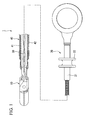
FIG 1 is an overall view of a treatment device for an endoscope of one embodiment of the present invention. -
FIG 2 is an exploded cross-sectional view of the treatment device for an endoscope on a distal end side. -
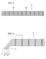
FIG 3 is a drawing showing a coiled sheath of the treatment device for an endoscope. -
FIG 4 is a view showing a winding method of the coiled sheath. -
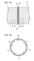
FIG 5A is an enlarged view of a fixing portion of the coiled sheath. -
FIG 5B is a cross-sectional view along line A-A ofFIG 5A . -
FIG 6 is a view showing a fixing portion in a modification of this embodiment. -
FIG 7 is a view showing a fixing portion in a modification of this embodiment. -
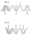
FIG 8 is a view showing an example of element wires of the coiled sheath and the positions of fixing portions. -
FIG 9 is a view showing an example of element wires of the coiled sheath and the positions of the fixing portions. -
FIG 10 is an enlarged view around a treatment part circumference in a treatment device for an endoscope of a modification of the present invention. -
FIG 11 is a cross-sectional view of a coiled sheath part in a modification of the present invention. - A treatment device for an endoscope of one embodiment of the present invention will be described below with reference to
FIGS. 1 to 8 . As shown inFIG 1 , a treatment device for an endoscope (hereinafter simply referred to as "treatment device") 1 of the present embodiment includes atreatment part 10 for treating tissue within a body cavity, a manipulatingpart 20 for manipulating thetreatment part 10, and two manipulation wires (manipulation shaft members) 30 that connect thetreatment part 10 and the manipulatingpart 20, and acoiled sheath part 40 through which themanipulation wires 30 are inserted so as to be able to advance and retract. -
FIG 2 is an enlarged cross-sectional view for a distal end portion of the treatment device 1 including thetreatment part 10. Thetreatment part 10 is configured by a pair of forceps members, that is, afirst forceps member 11 and asecond forceps member 12 that are rotatably coupled to each other by arotation shaft 13. Themanipulation wires 30 are connected closer to the proximal end side than therotation shaft 13 of therespective forceps members manipulation wires 30 are connected to the manipulating 20 through the inside of thecoiled sheath 40. - As shown in
FIG 1 , the manipulatingpart 20 includes anelongated body 21, and aslider 22 attached to thebody 21 so as to be slidable within a predetermined range in the direction of an axis. The proximal ends of themanipulation wires 30 are inserted into thebody 21, and are connected to theslider 22. Accordingly, by making theslider 22 slide with respect to thebody 21, themanipulation wires 30 can be advanced and retracted to open and close the pair offorceps members - The coiled
sheath part 40, which is a part to be endoscopically inserted into a body cavity, includes a coiledsheath 41 through which themanipulation wires 30 are inserted, and aresinous tube 42 that covers the outer peripheral surface of the coiledsheath 41. -
FIG 3 is an outline view of thecoiled sheath 41. The coiledsheath 41 is a long member formed by spirally winding metallic element wires. As shown inFIG 4 , thecoiled sheath 41 is a so-called multiple coiled sheath formed by densely winding a wire bundle, in which a plurality of element wires is arranged in the radial direction, in the shape of a loop. The number of element wires that are arranged in the radial direction is not particularly limited, and can be appropriately set.FIG 4 shows a five-strip coiled sheath around which a wire bundle F is wound, as an example. As shown inFIG 4 , the wire bundle F has five element wires from an element wire f1 to an element wire f5, and these element wires f1 to f5 are arranged in the radial direction. - A plurality of
fixing portions 48 that regulate a first relative movement between adjacent element wires is provided at intervals in the longitudinal direction in an intermediate portion between both ends of thecoiled sheath 41 in the longitudinal direction. The plurality offixing portions 48 is provided at intervals over almost the overall length of the sheath.
FIG 5A is an enlarged view of afixing portion 48, andFIG 5B is a cross-sectional view along line A-A ofFIG 5A . The fixingportion 48 is formed by performing laser welding in the circumferential direction of the coiledsheath 41. The element wires f1 to f5 that are arranged in the radial direction are fixed to each other by the fixingportion 48. Moreover, as shown inFIGS. 5A and 5B , the element wire f5 is also welded to the element wire f1 that is adjacent as the wire bundle F is wound in addition to the element wire f4. That is, in the fixingportion 48, parts of the wire bundle F that are adjacent as the wire bundle is wound in the shape of a loop as well as the element wires f1 to f5 that constitute the wire bundle F are fixed to each other. Thus, a second relative movement between adjoining parts is regulated. - As shown in
FIG 4 , although the interval L between adjacent fixingportions 48 can be appropriately set, the interval is preferably 10 mm or more and 500 mm or less, and more preferably from 20 mm to 200 mm. As the interval is made narrow to provide a larger number of fixing portions, the suppressing effect of a displacement of the element wire to be described below is enhanced. However, the time required for manufacture of the coiled sheath is long, and flexibility is deteriorated. If the number of fixing portions is too small, the suppressing effect of the displacement of the element wire is lowered.
The interval between the fixingportions 48 may be regular intervals over the entire coiledsheath 41, and the interval may be made different depending on parts. - As shown in
FIG 2 , a region with a predetermined length on adistal end 41A side of the coiledsheath 41 is worked by cutting or the like so as to have a flat outerperipheral surface 41 B. A connectingmember 43 for connecting thetreatment part 10 and thecoiled sheath part 40 is fixed to thedistal end 41 A of the coiledsheath 41 by welding or the like. Therotation shaft 13 is provided on the distal end side of the connectingmember 43, so that therotation shaft 13 is immovable relative to the connectingmember 43. - A substantially tubular engaging
member 45 is attached to the distal end side of thetube 42 by press-fitting or the like. The engagingmember 45 engages with the proximal end side of the outerperipheral surface 41 B the external diameter of which is made small by the above working. Although the proximal end of thetube 42 is inserted into thebody 21 of the manipulatingpart 20, this proximal end is not fixed to thebody 21, is movable in a predetermined range in the direction of the axis relative to the manipulatingpart 20, and is relatively rotatable around the axis.
On the other hand, since the proximal end of the coiledsheath 41 protrudes from thetube 42 and is fixed to thebody 21, thetube 42 is rotatable around the axis relative to the coiledsheath 41. - The operation when the treatment device 1 configured as described above is used will be described.
First, a user inserts the endoscope (not shown) into the body of a patient or the like, and advances the distal end of the endoscope to the vicinity of the target tissue in a body cavity to be treated (hereinafter referred to as "target tissue"). - Subsequently, the user retracts the
slider 22 with respect to thebody 21 to bring thetreatment part 10 into a closed state, and inserts thetreatment part 10 and thecoiled sheath part 40 of the treatment device 1 into a forceps channel (not shown) of the endoscope. Then, thetreatment part 10 is made to protrude from the forceps channel. - When treatment is performed, the
slider 22 is made to slide to the distal end side of thebody 21. Then, themanipulation wires 30 connected to theslider 22 advance with respect to the coiledsheath part 40. As described above, since therotation shaft 13 is immovable relative to the connectingmember 43 attached to the distal end of the coiledsheath part 40, thefirst forceps member 11 and thesecond forceps member 12 rotate about therotation shaft 13, respectively, and thetreatment part 10 opens. - In a case where the opening and closing orientations of the
forceps members treatment part 10 that have protruded from the distal end of the endoscope are not suitable for the target tissue, the user grips thebody 21 of the manipulatingpart 20 to rotate the body around the axis while holding thetube 42. If thebody 21 is rotated, the coiledsheath 41 and thetreatment part 10 attached to the distal end of the coiledsheath 41 rotate around the axis together with thebody 21. In this way, the opening and closing orientations of thetreatment part 10 can be adjusted. Since thetreatment part 10 and thebody 21 of the manipulatingpart 20 are connected by the coiledsheath 41, which is a multiple coiled sheath, the torque generated by the rotational operation of thebody 21 by the user as described above is favorably transmitted to thetreatment part 10 by the coiledsheath 41. As a result, thetreatment part 10 is rotated around the axis while following the rotational operation of thebody 21 favorably, so that the opening and closing orientations of thetreatment part 10 can be easily performed. - If the user locates the target tissue between the opened
forceps members treatment part 10 and makes theslider 22 slide to the proximal end side of thebody 21, the distal end side of theforceps members treatment part 10. - Generally, although the multiple coiled sheath is excellent in torque transmissibility, there is a drawback in that the coiled sheath is inferior to resistance (resistance to compression) against the compressive force of a loop in the direction of the axis. If a compressive force in the direction of the axis acts on an ordinary multiple coiled sheath, a so-called "the displacement of the element wire" in which slippage occurs between element wires that constitute the multiple coiled sheath may occur. Since the overall coiled sheath shrinks in the direction of the axis if the displacement of the element wire occurs, a manipulation force for pulling the manipulation wires is absorbed, and transmission of the manipulation force to the treatment part reduces.
However, in the coiledsheath 41 of the present embodiment, the plurality of fixingportions 48 is provided at intervals at the intermediate portion between both ends. Therefore, even in a case where the displacement of the element wire occurs, the displacement of the element wire is limited to a region between the fixing portions. Accordingly, the overall coiled sheath does not shrink excessively even if a compressive force in the direction of the axis is received, and the manipulation force is favorably transmitted to thetreatment part 10 when themanipulation wires 30 are pulled. - According to the treatment device 1 of the present embodiment, the coiled
sheath 41 having the plurality of fixingportion 48 is used for the coiledsheath part 40. Therefore, even if two types of coiled sheaths are coaxially arranged as in the treatment device described in Patent Document 1, to balance a favorable rotational operation of thetreatment part 10 and a favorable transmission of the manipulation force to thetreatment part 10 can be achieved to a high level. As a result, it is possible to provide a treatment device for an endoscope in which torque transmissibility is high and a manipulation force is efficiently transmitted to the treatment part, while being capable of reduction in diameter. - Additionally, in the fixing
portion 48, not only the respective element wires f1 to f5 of the wire bundle F are fixed to each other, but also the parts of the wire bundle F that are adjacent as being wound are fixed to each other. Accordingly, not only the displacement of the element wires f1 to f5, but also slippage between the parts of the wire bundle F can be suppressed, and a situation where the overall wire bundle causes the displacement can be favorably suppressed. - Moreover, since the fixing
portion 48 is formed by performing laser welding in a circumferential direction of the coiled sheath, the fixingportion 48 can be easily formed. - Although an example in which the fixing portion is formed by laser welding has been described in the present embodiment, a method of forming the fixing portion is not limited to the above.
For example, as in a modification shown inFIG 6 , a fixingportion 53 may be formed by attaching apipe 50, having a through-hole 51 communicating with an inner cavity at the outer peripheral surface thereof, to the coiled sheath, and pouring abrazing material 52 from the through-hole 51. Additionally, although not shown, a fixing portion may be formed using pipes intermittently formed in the circumferential direction and having a slit communicating with an inner cavity, and soldering and welding the slit portion. - Moreover, for example, particularly in a case where the coiled sheath part is long, the coiled sheath part may be configured by a plurality of multiple coiled sheaths, and in a modification shown in
FIG 7 , the above-described fixing may be formed at a connecting portion between a multiple coiled sheath 55 and a multiple coiledsheath 56. By using the plurality of multiple coiled sheaths with a moderate length, there are advantages in that the space required for laser welding is small, a large-sized facility is less necessary, and assemblability is improved.
In addition, the fixingportion 48 using laser welding may be formed at a connecting part between the plurality of multiple coiled sheaths. - Although one embodiment of the present invention has been described hitherto, the technical scope of the present invention is not limited to the above embodiment, and various modifications may be made without departing from the scope of the present invention.
-
FIGS. 8 and 9 are views showing the relationship between the positions where the fixing portions are provided, and loops of element wires. As shown inFIG 8 , attention is paid to a particular element wire (inFIG 8 , the element wire f1 is shown as an example) that forms a multiple coil. The fixingportions 48 may be provided so that the phase positions of parts, which are fixed by the fixingportions 48, in a loop formed by the element wire f1 are opposite each other across the axis of the loop inadjacent fixing portions 48. Then, the force that acts on the element wire f1 through the fixingportions 48 can be favorably decentralized in the circumferential direction of the coiled sheath. As a result, the fixingpotions 48 neither make it easy nor difficult for the coiled sheath to curve in the specific direction. Even if the fixing portions may be provided so that the phases of parts fixed by the fixing portions displace by a predetermined degree of angle (for example, 90 degrees, 120 degrees, or the like) in adjacent fixing portions, the same effects can be obtained. - In contrast, as shown in
FIG 9 , if the fixing portions are provided so that fixing using the fixing portions is performed in specific phase positions in the loop formed by the element wire f1, a coiled sheath that is hardly bent on the phase position side can be provided. Accordingly, the fixing portions are useful for, for example, a case where a treatment device that is easily bent in a specific direction is required. - Additionally, although the fixing portions are provided over the overall length of the coiled sheath, the present invention is not limited to this, and a coiled sheath having the fixing portions at only a portion of the coiled sheath part (particularly, a required part) may be used. In a
treatment device 61 for an endoscope of a modification shown inFIG 10 , a single-line coiledsheath 63 around which one element wire is wound is used for the region of the coiledsheath part 62 with a predetermined length on thetreatment part 10 side that is curved by the curving manipulation of the endoscope. The coiledsheath 41 is connected to the proximal end side of the single-line coiledsheath 63 via apipe 64. A treatment device that follows the curve of an endoscope to be inserted favorably and that also suppresses the displacement of the element wire can be provided by arranging the single-line coiledsheath 63 having excellent flexibility on the distal end side of the coiledsheath part 62.
Although the length of the single-line coiledsheath 63 can be appropriately set in consideration of an endoscope to be inserted or the like, if the length is set to be from 100 mm or more and to 300 mm or less, this is preferably because the coiled sheath can be favorably used for a number of endoscope apparatuses. - Additionally, for example, in a case where it is not necessary to reduce the diameter of the treatment device, the coiled sheath part may be formed using a multiple multi-layer coiled
sheath 70 using coiledsheaths portions 48 as a modification shown inFIG 11 . At this time, the positions of the fixingportions 48 of the respective coiled sheaths 71 to 73 in the multiple and multi-layer coiledsheath 70 may be the same in the direction of the axis of the multiple multi-layer coiledsheath 70 as shown inFIG 11 , or may displace. Here, in the configuration in which the positions of the fixing portions displace, it is preferable to determine the interval between the fixing portions in consideration of the fixing portions of all the coiled sheaths.
Moreover, a coiled sheath part may be configured using a coiled sheath in which a coiled sheath having a plurality of fixing portions and a single-line coiled sheath are combined. - Moreover, although an example in which the manipulation wires are used as the manipulation shaft members has been described in the above-described embodiment, instead of this, the manipulation shaft members may be configured using rods or pipes or combining these.
In addition, although an example in which the treatment part includes a pair of forceps members has been described in the above-described embodiment, the treatment part in the treatment device of the present invention is not limited to this. That is, for example, a snare wire, so-called two-leg forceps, or the like can be applied to all treatment parts that need to adjust its orientation with respect to the target tissue to be treated. - While preferred embodiments of the present invention have been described, the present invention is not limited to the embodiments. Additions, omissions, substitutions, and other variations may be made to the present invention without departing from the spirit and scope of the present invention. The present invention is not limited by the above description, but by the appended claims.
- According to the present invention, it is possible to provide a treatment device for an endoscope in which torque transmissibility is high and a manipulation force is efficiently transmitted to the treatment part, while being capable of reduction in diameter.
-
- 1, 61:
- TREATMENT DEVICE FOR ENDOSCOPE
- 10:
- TREATMENT PART
- 20:
- MANIPULATING PART
- 30:
- MANIPULATION WIRE (MANIPULATION SHAFT MEMBER)
- 41,71,72,73:
- COILED SHEATH (MULTIPLE COILED SHEATH)
- 48,53:
- FIXING PORTION
- F:
- WIRE BUNDLE
- f1, f2, f3, f4, f5:
- ELEMENT WIRE
Claims (4)
- A treatment device for an endoscope comprising:a treatment part that is adopted to treat tissue within a body cavity;a manipulating part that is adopted to manipulate the treatment part;a manipulation shaft member that connects the treatment part and the manipulating part; anda multiple coiled sheath that is formed by spirally winding an wire bundle having a plurality of element wires arranged in a radial direction, wherein the manipulation shaft member is inserted into the multiple coiled sheath so that the manipulation shaft member is capable of being advanced and retracted,wherein the multiple coiled sheath has a fixing portion that is arranged at intervals in a longitudinal direction and regulates a first relative movement between the plurality of element wires and a second relative movement between a part of the wire bundle that are adjacent to each other as being spirally wound.
- The treatment device for an endoscope according to Claim 1,
wherein the interval of the fixing portion that is adjacent to each other is 10 mm or more and 500 mm or less. - The treatment device for an endoscope according to Claim 1 or 2,
wherein the fixing portion is formed by performing laser welding over a circumferential direction of the multiple coiled sheath. - The treatment device for an endoscope according to Claim 1 or 2,
wherein the fixing portion is provided over the overall length of the multiple coiled sheath.
Applications Claiming Priority (2)
| Application Number | Priority Date | Filing Date | Title |
|---|---|---|---|
| JP2010293229 | 2010-12-28 | ||
| PCT/JP2011/079816 WO2012090859A1 (en) | 2010-12-28 | 2011-12-22 | Treatment instrument for endoscopes |
Publications (3)
| Publication Number | Publication Date |
|---|---|
| EP2529680A1 true EP2529680A1 (en) | 2012-12-05 |
| EP2529680A4 EP2529680A4 (en) | 2012-12-05 |
| EP2529680B1 EP2529680B1 (en) | 2016-06-01 |
Family
ID=46382965
Family Applications (1)
| Application Number | Title | Priority Date | Filing Date |
|---|---|---|---|
| EP11853583.0A Not-in-force EP2529680B1 (en) | 2010-12-28 | 2011-12-22 | Treatment device for endoscope |
Country Status (5)
| Country | Link |
|---|---|
| US (1) | US8523899B2 (en) |
| EP (1) | EP2529680B1 (en) |
| JP (1) | JP5132846B2 (en) |
| CN (1) | CN102762158B (en) |
| WO (1) | WO2012090859A1 (en) |
Families Citing this family (4)
| Publication number | Priority date | Publication date | Assignee | Title |
|---|---|---|---|---|
| KR102742976B1 (en) | 2016-02-05 | 2024-12-16 | 보드 오브 리전츠, 더 유니버시티 오브 텍사스 시스템 | Surgical apparatus |
| KR102436601B1 (en) | 2016-02-05 | 2022-08-25 | 보드 오브 리전츠 오브 더 유니버시티 오브 텍사스 시스템 | Medical device in steerable lumen |
| EP3484568B2 (en) | 2016-07-13 | 2025-07-16 | Perfuze Limited | High flexibility, kink resistant catheter shaft |
| ES2894768T3 (en) | 2017-12-15 | 2022-02-15 | Perfuze Ltd | Improved catheters and devices and systems incorporating such catheters |
Family Cites Families (64)
| Publication number | Priority date | Publication date | Assignee | Title |
|---|---|---|---|---|
| BE476559A (en) * | 1947-07-31 | |||
| US3267697A (en) * | 1963-10-23 | 1966-08-23 | Eaton Yale & Towne | Universal joint |
| US3618613A (en) * | 1969-05-19 | 1971-11-09 | Heyer Schulte Corp | Antithrombotic intravascular catheter reinforced with nonkinking means |
| US3749085A (en) * | 1970-06-26 | 1973-07-31 | J Willson | Vascular tissue removing device |
| US3749086A (en) * | 1972-07-24 | 1973-07-31 | Medical Evaluation Devices & I | Spring guide with flexible distal tip |
| US3879516A (en) * | 1972-12-07 | 1975-04-22 | Technibiotics | Method of constructing a catheter |
| US3924632A (en) * | 1972-12-07 | 1975-12-09 | William A Cook | Fiber glass reinforced catheter |
| US4020829A (en) * | 1975-10-23 | 1977-05-03 | Willson James K V | Spring guide wire with torque control for catheterization of blood vessels and method of using same |
| JPS57153629A (en) * | 1981-03-19 | 1982-09-22 | Olympus Optical Co | Connection of coil for endoscope |
| JPS5886129A (en) * | 1981-11-17 | 1983-05-23 | 旭光学工業株式会社 | Flexible tube of endoscope and production thereof |
| US4493329A (en) * | 1982-08-19 | 1985-01-15 | Lynn Crawford | Implantable electrode having different stiffening and curvature maintaining characteristics along its length |
| US4538622A (en) * | 1983-11-10 | 1985-09-03 | Advanced Cardiovascular Systems, Inc. | Guide wire for catheters |
| US4721116A (en) * | 1985-06-04 | 1988-01-26 | Schintgen Jean Marie | Retractable needle biopsy forceps and improved control cable therefor |
| ES2000247A4 (en) * | 1986-05-23 | 1988-02-01 | Sarcem Sa | CATHETER-GUIDE |
| US4719924A (en) * | 1986-09-09 | 1988-01-19 | C. R. Bard, Inc. | Small diameter steerable guidewire with adjustable tip |
| US6210395B1 (en) * | 1987-09-30 | 2001-04-03 | Lake Region Mfg., Inc. | Hollow lumen cable apparatus |
| US4889327B1 (en) * | 1988-03-15 | 1994-12-20 | Harris Trust And Savings Bank | Multiple-strand torsion spring |
| US4951677A (en) * | 1988-03-21 | 1990-08-28 | Prutech Research And Development Partnership Ii | Acoustic imaging catheter and the like |
| US5372138A (en) * | 1988-03-21 | 1994-12-13 | Boston Scientific Corporation | Acousting imaging catheters and the like |
| US4932419A (en) * | 1988-03-21 | 1990-06-12 | Boston Scientific Corporation | Multi-filar, cross-wound coil for medical devices |
| US5065769A (en) * | 1988-11-23 | 1991-11-19 | Boston Scientific Corporation | Small diameter guidewires of multi-filar, cross-wound coils |
| US4985022A (en) * | 1988-11-23 | 1991-01-15 | Med Institute, Inc. | Catheter having durable and flexible segments |
| US5052404A (en) * | 1989-03-02 | 1991-10-01 | The Microspring Company, Inc. | Torque transmitter |
| US5002041A (en) * | 1989-05-12 | 1991-03-26 | Kabushiki Kaisha Machida Seisakusho | Bending device and flexible tube structure |
| US5019057A (en) * | 1989-10-23 | 1991-05-28 | Cordis Corporation | Catheter having reinforcing strands |
| US5176660A (en) * | 1989-10-23 | 1993-01-05 | Cordis Corporation | Catheter having reinforcing strands |
| JPH0759236B2 (en) * | 1990-06-29 | 1995-06-28 | オリンパス光学工業株式会社 | Endoscopic treatment device |
| US5438997A (en) * | 1991-03-13 | 1995-08-08 | Sieben; Wayne | Intravascular imaging apparatus and methods for use and manufacture |
| US5445155A (en) * | 1991-03-13 | 1995-08-29 | Scimed Life Systems Incorporated | Intravascular imaging apparatus and methods for use and manufacture |
| US5353798A (en) * | 1991-03-13 | 1994-10-11 | Scimed Life Systems, Incorporated | Intravascular imaging apparatus and methods for use and manufacture |
| US5306252A (en) * | 1991-07-18 | 1994-04-26 | Kabushiki Kaisha Kobe Seiko Sho | Catheter guide wire and catheter |
| US5630806A (en) * | 1991-08-13 | 1997-05-20 | Hudson International Conductors | Spiral wrapped medical tubing |
| JPH0681504U (en) * | 1993-05-11 | 1994-11-22 | オリンパス光学工業株式会社 | Endoscopic treatment tool |
| US5429597A (en) * | 1994-03-01 | 1995-07-04 | Boston Scientific Corporation | Kink resistant balloon catheter and method for use |
| US5441516A (en) * | 1994-03-03 | 1995-08-15 | Scimed Lifesystems Inc. | Temporary stent |
| US5902290A (en) * | 1994-03-14 | 1999-05-11 | Advanced Cardiovascular Systems, Inc. | Catheter providing intraluminal access |
| JP3713294B2 (en) * | 1994-03-31 | 2005-11-09 | オリンパス株式会社 | Endoscopic treatment tool |
| US5762995A (en) * | 1995-01-13 | 1998-06-09 | Fuji Photo Optical Co., Ltd. | Flexible sheathing tube construction, and method for fabrication thereof |
| US5766197A (en) * | 1995-04-14 | 1998-06-16 | Portlyn Corporation | Surgical cutting instrument with anti-torgue outer jacket |
| JP3498426B2 (en) * | 1995-05-16 | 2004-02-16 | 富士写真光機株式会社 | Endoscope flexible tube |
| US20030069522A1 (en) * | 1995-12-07 | 2003-04-10 | Jacobsen Stephen J. | Slotted medical device |
| JP3283195B2 (en) * | 1996-11-01 | 2002-05-20 | 旭光学工業株式会社 | Endoscope flexible tube |
| US5951539A (en) * | 1997-06-10 | 1999-09-14 | Target Therpeutics, Inc. | Optimized high performance multiple coil spiral-wound vascular catheter |
| US5971940A (en) * | 1998-02-20 | 1999-10-26 | Scimed Life Systems, Inc. | Surgical instrument with locking feature, split distal housing, and sharpened jaws |
| US6290692B1 (en) * | 1998-11-03 | 2001-09-18 | Daniel J. Klima | Catheter support structure |
| US6221066B1 (en) * | 1999-03-09 | 2001-04-24 | Micrus Corporation | Shape memory segmented detachable coil |
| JP4898993B2 (en) * | 2000-01-28 | 2012-03-21 | クック メディカル テクノロジーズ エルエルシー | Intravascular medical device with multiple wires |
| US20040006362A1 (en) * | 2002-07-02 | 2004-01-08 | Dean Schaefer | Uniaxial multifilar vaso-occlusive device with high stretch resistance and low buckling strength |
| US7158837B2 (en) * | 2002-07-10 | 2007-01-02 | Oscor Inc. | Low profile cardiac leads |
| US6920361B2 (en) * | 2003-02-14 | 2005-07-19 | Medtronic, Inc. | Reverse wound electrodes |
| US7182735B2 (en) * | 2003-02-26 | 2007-02-27 | Scimed Life Systems, Inc. | Elongated intracorporal medical device |
| US6896671B2 (en) * | 2003-03-12 | 2005-05-24 | Arrow International, Inc. | Catheter with limited longitudinal extension |
| US20040199052A1 (en) * | 2003-04-01 | 2004-10-07 | Scimed Life Systems, Inc. | Endoscopic imaging system |
| US7763012B2 (en) * | 2003-09-02 | 2010-07-27 | St. Jude Medical, Cardiology Division, Inc. | Devices and methods for crossing a chronic total occlusion |
| US20050054952A1 (en) * | 2003-09-05 | 2005-03-10 | Scimed Life Systems, Inc. | Elongated medical device for intracorporal use |
| US7785273B2 (en) * | 2003-09-22 | 2010-08-31 | Boston Scientific Scimed, Inc. | Guidewire with reinforcing member |
| JP4668643B2 (en) * | 2005-02-23 | 2011-04-13 | オリンパスメディカルシステムズ株式会社 | Endoscope device |
| JP2008148738A (en) * | 2006-12-14 | 2008-07-03 | Olympus Medical Systems Corp | Endoscopic treatment tool |
| JP4526544B2 (en) * | 2007-02-08 | 2010-08-18 | オリンパスメディカルシステムズ株式会社 | Endoscopic treatment tool |
| JP5042700B2 (en) * | 2007-02-08 | 2012-10-03 | オリンパスメディカルシステムズ株式会社 | Endoscopic treatment tool |
| EP1955657B1 (en) * | 2007-02-08 | 2011-01-12 | Olympus Medical Systems Corp. | Treatment tool for endoscope |
| US7998150B2 (en) * | 2007-09-28 | 2011-08-16 | Olympus Medical Systems Corp. | Suturing device |
| US8728089B2 (en) * | 2008-03-28 | 2014-05-20 | Olympus Medical Systems Corp. | Endoscope treatment instrument |
| CN102281826B (en) * | 2009-03-18 | 2013-11-06 | 奥林巴斯医疗株式会社 | Endoscope Treatment Instruments |
-
2011
- 2011-12-22 WO PCT/JP2011/079816 patent/WO2012090859A1/en not_active Ceased
- 2011-12-22 CN CN201180009936.5A patent/CN102762158B/en active Active
- 2011-12-22 EP EP11853583.0A patent/EP2529680B1/en not_active Not-in-force
- 2011-12-22 JP JP2012537252A patent/JP5132846B2/en active Active
-
2012
- 2012-08-22 US US13/591,573 patent/US8523899B2/en active Active
Also Published As
| Publication number | Publication date |
|---|---|
| US8523899B2 (en) | 2013-09-03 |
| JPWO2012090859A1 (en) | 2014-06-05 |
| US20120316543A1 (en) | 2012-12-13 |
| CN102762158A (en) | 2012-10-31 |
| CN102762158B (en) | 2014-11-05 |
| JP5132846B2 (en) | 2013-01-30 |
| EP2529680B1 (en) | 2016-06-01 |
| EP2529680A4 (en) | 2012-12-05 |
| WO2012090859A1 (en) | 2012-07-05 |
Similar Documents
| Publication | Publication Date | Title |
|---|---|---|
| CN102281826B (en) | Endoscope Treatment Instruments | |
| US20220378405A1 (en) | Braided hemostasis shaft for improved torsional response | |
| CN101238971B (en) | Treatment tool for endoscope | |
| US6015381A (en) | Endoscopic treatment tool | |
| EP2322076B1 (en) | Treating endoscope | |
| JP5325520B2 (en) | Endoscopic treatment tool | |
| JP6411745B2 (en) | Medical equipment | |
| EP2612608B1 (en) | Medical coil, method of manufacturing same, and medical apparatus | |
| CN201131730Y (en) | Endoscope Treatment Instruments | |
| EP2111806B1 (en) | Endoscope treatment instrument | |
| JP2007268270A (en) | Endscope ancillary attaching device | |
| AU2007201563B2 (en) | Medical tubular assembly | |
| EP2529680B1 (en) | Treatment device for endoscope | |
| JP5171471B2 (en) | Endoscopic treatment tool | |
| JPWO2017175373A1 (en) | Flexible manipulator |
Legal Events
| Date | Code | Title | Description |
|---|---|---|---|
| PUAI | Public reference made under article 153(3) epc to a published international application that has entered the european phase |
Free format text: ORIGINAL CODE: 0009012 |
|
| 17P | Request for examination filed |
Effective date: 20120827 |
|
| A4 | Supplementary search report drawn up and despatched |
Effective date: 20121008 |
|
| AK | Designated contracting states |
Kind code of ref document: A1 Designated state(s): AL AT BE BG CH CY CZ DE DK EE ES FI FR GB GR HR HU IE IS IT LI LT LU LV MC MK MT NL NO PL PT RO RS SE SI SK SM TR |
|
| DAX | Request for extension of the european patent (deleted) | ||
| RAP1 | Party data changed (applicant data changed or rights of an application transferred) |
Owner name: OLYMPUS CORPORATION |
|
| GRAP | Despatch of communication of intention to grant a patent |
Free format text: ORIGINAL CODE: EPIDOSNIGR1 |
|
| INTG | Intention to grant announced |
Effective date: 20151222 |
|
| GRAS | Grant fee paid |
Free format text: ORIGINAL CODE: EPIDOSNIGR3 |
|
| GRAA | (expected) grant |
Free format text: ORIGINAL CODE: 0009210 |
|
| AK | Designated contracting states |
Kind code of ref document: B1 Designated state(s): AL AT BE BG CH CY CZ DE DK EE ES FI FR GB GR HR HU IE IS IT LI LT LU LV MC MK MT NL NO PL PT RO RS SE SI SK SM TR |
|
| REG | Reference to a national code |
Ref country code: GB Ref legal event code: FG4D |
|
| REG | Reference to a national code |
Ref country code: CH Ref legal event code: EP Ref country code: AT Ref legal event code: REF Ref document number: 803361 Country of ref document: AT Kind code of ref document: T Effective date: 20160615 |
|
| REG | Reference to a national code |
Ref country code: IE Ref legal event code: FG4D |
|
| REG | Reference to a national code |
Ref country code: DE Ref legal event code: R096 Ref document number: 602011027176 Country of ref document: DE |
|
| REG | Reference to a national code |
Ref country code: LT Ref legal event code: MG4D |
|
| RAP2 | Party data changed (patent owner data changed or rights of a patent transferred) |
Owner name: OLYMPUS CORPORATION |
|
| RAP2 | Party data changed (patent owner data changed or rights of a patent transferred) |
Owner name: OLYMPUS CORPORATION |
|
| REG | Reference to a national code |
Ref country code: NL Ref legal event code: MP Effective date: 20160601 |
|
| PG25 | Lapsed in a contracting state [announced via postgrant information from national office to epo] |
Ref country code: LT Free format text: LAPSE BECAUSE OF FAILURE TO SUBMIT A TRANSLATION OF THE DESCRIPTION OR TO PAY THE FEE WITHIN THE PRESCRIBED TIME-LIMIT Effective date: 20160601 Ref country code: FI Free format text: LAPSE BECAUSE OF FAILURE TO SUBMIT A TRANSLATION OF THE DESCRIPTION OR TO PAY THE FEE WITHIN THE PRESCRIBED TIME-LIMIT Effective date: 20160601 Ref country code: NO Free format text: LAPSE BECAUSE OF FAILURE TO SUBMIT A TRANSLATION OF THE DESCRIPTION OR TO PAY THE FEE WITHIN THE PRESCRIBED TIME-LIMIT Effective date: 20160901 |
|
| REG | Reference to a national code |
Ref country code: AT Ref legal event code: MK05 Ref document number: 803361 Country of ref document: AT Kind code of ref document: T Effective date: 20160601 |
|
| PG25 | Lapsed in a contracting state [announced via postgrant information from national office to epo] |
Ref country code: GR Free format text: LAPSE BECAUSE OF FAILURE TO SUBMIT A TRANSLATION OF THE DESCRIPTION OR TO PAY THE FEE WITHIN THE PRESCRIBED TIME-LIMIT Effective date: 20160902 Ref country code: HR Free format text: LAPSE BECAUSE OF FAILURE TO SUBMIT A TRANSLATION OF THE DESCRIPTION OR TO PAY THE FEE WITHIN THE PRESCRIBED TIME-LIMIT Effective date: 20160601 Ref country code: LV Free format text: LAPSE BECAUSE OF FAILURE TO SUBMIT A TRANSLATION OF THE DESCRIPTION OR TO PAY THE FEE WITHIN THE PRESCRIBED TIME-LIMIT Effective date: 20160601 Ref country code: SE Free format text: LAPSE BECAUSE OF FAILURE TO SUBMIT A TRANSLATION OF THE DESCRIPTION OR TO PAY THE FEE WITHIN THE PRESCRIBED TIME-LIMIT Effective date: 20160601 Ref country code: NL Free format text: LAPSE BECAUSE OF FAILURE TO SUBMIT A TRANSLATION OF THE DESCRIPTION OR TO PAY THE FEE WITHIN THE PRESCRIBED TIME-LIMIT Effective date: 20160601 Ref country code: ES Free format text: LAPSE BECAUSE OF FAILURE TO SUBMIT A TRANSLATION OF THE DESCRIPTION OR TO PAY THE FEE WITHIN THE PRESCRIBED TIME-LIMIT Effective date: 20160601 Ref country code: RS Free format text: LAPSE BECAUSE OF FAILURE TO SUBMIT A TRANSLATION OF THE DESCRIPTION OR TO PAY THE FEE WITHIN THE PRESCRIBED TIME-LIMIT Effective date: 20160601 |
|
| PG25 | Lapsed in a contracting state [announced via postgrant information from national office to epo] |
Ref country code: SK Free format text: LAPSE BECAUSE OF FAILURE TO SUBMIT A TRANSLATION OF THE DESCRIPTION OR TO PAY THE FEE WITHIN THE PRESCRIBED TIME-LIMIT Effective date: 20160601 Ref country code: IT Free format text: LAPSE BECAUSE OF FAILURE TO SUBMIT A TRANSLATION OF THE DESCRIPTION OR TO PAY THE FEE WITHIN THE PRESCRIBED TIME-LIMIT Effective date: 20160601 Ref country code: EE Free format text: LAPSE BECAUSE OF FAILURE TO SUBMIT A TRANSLATION OF THE DESCRIPTION OR TO PAY THE FEE WITHIN THE PRESCRIBED TIME-LIMIT Effective date: 20160601 Ref country code: IS Free format text: LAPSE BECAUSE OF FAILURE TO SUBMIT A TRANSLATION OF THE DESCRIPTION OR TO PAY THE FEE WITHIN THE PRESCRIBED TIME-LIMIT Effective date: 20161001 Ref country code: CZ Free format text: LAPSE BECAUSE OF FAILURE TO SUBMIT A TRANSLATION OF THE DESCRIPTION OR TO PAY THE FEE WITHIN THE PRESCRIBED TIME-LIMIT Effective date: 20160601 Ref country code: RO Free format text: LAPSE BECAUSE OF FAILURE TO SUBMIT A TRANSLATION OF THE DESCRIPTION OR TO PAY THE FEE WITHIN THE PRESCRIBED TIME-LIMIT Effective date: 20160601 |
|
| PG25 | Lapsed in a contracting state [announced via postgrant information from national office to epo] |
Ref country code: PT Free format text: LAPSE BECAUSE OF FAILURE TO SUBMIT A TRANSLATION OF THE DESCRIPTION OR TO PAY THE FEE WITHIN THE PRESCRIBED TIME-LIMIT Effective date: 20161003 Ref country code: AT Free format text: LAPSE BECAUSE OF FAILURE TO SUBMIT A TRANSLATION OF THE DESCRIPTION OR TO PAY THE FEE WITHIN THE PRESCRIBED TIME-LIMIT Effective date: 20160601 Ref country code: SM Free format text: LAPSE BECAUSE OF FAILURE TO SUBMIT A TRANSLATION OF THE DESCRIPTION OR TO PAY THE FEE WITHIN THE PRESCRIBED TIME-LIMIT Effective date: 20160601 Ref country code: BE Free format text: LAPSE BECAUSE OF FAILURE TO SUBMIT A TRANSLATION OF THE DESCRIPTION OR TO PAY THE FEE WITHIN THE PRESCRIBED TIME-LIMIT Effective date: 20160601 Ref country code: PL Free format text: LAPSE BECAUSE OF FAILURE TO SUBMIT A TRANSLATION OF THE DESCRIPTION OR TO PAY THE FEE WITHIN THE PRESCRIBED TIME-LIMIT Effective date: 20160601 |
|
| REG | Reference to a national code |
Ref country code: DE Ref legal event code: R097 Ref document number: 602011027176 Country of ref document: DE |
|
| PLBE | No opposition filed within time limit |
Free format text: ORIGINAL CODE: 0009261 |
|
| STAA | Information on the status of an ep patent application or granted ep patent |
Free format text: STATUS: NO OPPOSITION FILED WITHIN TIME LIMIT |
|
| 26N | No opposition filed |
Effective date: 20170302 |
|
| PG25 | Lapsed in a contracting state [announced via postgrant information from national office to epo] |
Ref country code: DK Free format text: LAPSE BECAUSE OF FAILURE TO SUBMIT A TRANSLATION OF THE DESCRIPTION OR TO PAY THE FEE WITHIN THE PRESCRIBED TIME-LIMIT Effective date: 20160601 Ref country code: SI Free format text: LAPSE BECAUSE OF FAILURE TO SUBMIT A TRANSLATION OF THE DESCRIPTION OR TO PAY THE FEE WITHIN THE PRESCRIBED TIME-LIMIT Effective date: 20160601 |
|
| REG | Reference to a national code |
Ref country code: CH Ref legal event code: PL |
|
| GBPC | Gb: european patent ceased through non-payment of renewal fee |
Effective date: 20161222 |
|
| PG25 | Lapsed in a contracting state [announced via postgrant information from national office to epo] |
Ref country code: MC Free format text: LAPSE BECAUSE OF FAILURE TO SUBMIT A TRANSLATION OF THE DESCRIPTION OR TO PAY THE FEE WITHIN THE PRESCRIBED TIME-LIMIT Effective date: 20160601 |
|
| REG | Reference to a national code |
Ref country code: FR Ref legal event code: ST Effective date: 20170831 |
|
| REG | Reference to a national code |
Ref country code: IE Ref legal event code: MM4A |
|
| PG25 | Lapsed in a contracting state [announced via postgrant information from national office to epo] |
Ref country code: LI Free format text: LAPSE BECAUSE OF NON-PAYMENT OF DUE FEES Effective date: 20161231 Ref country code: FR Free format text: LAPSE BECAUSE OF NON-PAYMENT OF DUE FEES Effective date: 20170102 Ref country code: LU Free format text: LAPSE BECAUSE OF NON-PAYMENT OF DUE FEES Effective date: 20161222 Ref country code: CH Free format text: LAPSE BECAUSE OF NON-PAYMENT OF DUE FEES Effective date: 20161231 |
|
| PG25 | Lapsed in a contracting state [announced via postgrant information from national office to epo] |
Ref country code: GB Free format text: LAPSE BECAUSE OF NON-PAYMENT OF DUE FEES Effective date: 20161222 Ref country code: IE Free format text: LAPSE BECAUSE OF NON-PAYMENT OF DUE FEES Effective date: 20161222 |
|
| PG25 | Lapsed in a contracting state [announced via postgrant information from national office to epo] |
Ref country code: CY Free format text: LAPSE BECAUSE OF FAILURE TO SUBMIT A TRANSLATION OF THE DESCRIPTION OR TO PAY THE FEE WITHIN THE PRESCRIBED TIME-LIMIT Effective date: 20160601 Ref country code: HU Free format text: LAPSE BECAUSE OF FAILURE TO SUBMIT A TRANSLATION OF THE DESCRIPTION OR TO PAY THE FEE WITHIN THE PRESCRIBED TIME-LIMIT; INVALID AB INITIO Effective date: 20111222 |
|
| PG25 | Lapsed in a contracting state [announced via postgrant information from national office to epo] |
Ref country code: TR Free format text: LAPSE BECAUSE OF FAILURE TO SUBMIT A TRANSLATION OF THE DESCRIPTION OR TO PAY THE FEE WITHIN THE PRESCRIBED TIME-LIMIT Effective date: 20160601 Ref country code: MK Free format text: LAPSE BECAUSE OF FAILURE TO SUBMIT A TRANSLATION OF THE DESCRIPTION OR TO PAY THE FEE WITHIN THE PRESCRIBED TIME-LIMIT Effective date: 20160601 |
|
| PG25 | Lapsed in a contracting state [announced via postgrant information from national office to epo] |
Ref country code: BG Free format text: LAPSE BECAUSE OF FAILURE TO SUBMIT A TRANSLATION OF THE DESCRIPTION OR TO PAY THE FEE WITHIN THE PRESCRIBED TIME-LIMIT Effective date: 20160601 |
|
| PG25 | Lapsed in a contracting state [announced via postgrant information from national office to epo] |
Ref country code: MT Free format text: LAPSE BECAUSE OF NON-PAYMENT OF DUE FEES Effective date: 20161222 |
|
| PG25 | Lapsed in a contracting state [announced via postgrant information from national office to epo] |
Ref country code: AL Free format text: LAPSE BECAUSE OF FAILURE TO SUBMIT A TRANSLATION OF THE DESCRIPTION OR TO PAY THE FEE WITHIN THE PRESCRIBED TIME-LIMIT Effective date: 20160601 |
|
| PGFP | Annual fee paid to national office [announced via postgrant information from national office to epo] |
Ref country code: DE Payment date: 20181210 Year of fee payment: 8 |
|
| REG | Reference to a national code |
Ref country code: DE Ref legal event code: R119 Ref document number: 602011027176 Country of ref document: DE |
|
| PG25 | Lapsed in a contracting state [announced via postgrant information from national office to epo] |
Ref country code: DE Free format text: LAPSE BECAUSE OF NON-PAYMENT OF DUE FEES Effective date: 20200701 |