EP2529652A1 - A cleaning appliance - Google Patents
A cleaning appliance Download PDFInfo
- Publication number
- EP2529652A1 EP2529652A1 EP11168516A EP11168516A EP2529652A1 EP 2529652 A1 EP2529652 A1 EP 2529652A1 EP 11168516 A EP11168516 A EP 11168516A EP 11168516 A EP11168516 A EP 11168516A EP 2529652 A1 EP2529652 A1 EP 2529652A1
- Authority
- EP
- European Patent Office
- Prior art keywords
- handle
- nozzle
- cleaning appliance
- main body
- appliance according
- Prior art date
- Legal status (The legal status is an assumption and is not a legal conclusion. Google has not performed a legal analysis and makes no representation as to the accuracy of the status listed.)
- Granted
Links
Images




Classifications
-
- A—HUMAN NECESSITIES
- A47—FURNITURE; DOMESTIC ARTICLES OR APPLIANCES; COFFEE MILLS; SPICE MILLS; SUCTION CLEANERS IN GENERAL
- A47L—DOMESTIC WASHING OR CLEANING; SUCTION CLEANERS IN GENERAL
- A47L9/00—Details or accessories of suction cleaners, e.g. mechanical means for controlling the suction or for effecting pulsating action; Storing devices specially adapted to suction cleaners or parts thereof; Carrying-vehicles specially adapted for suction cleaners
- A47L9/02—Nozzles
-
- A—HUMAN NECESSITIES
- A47—FURNITURE; DOMESTIC ARTICLES OR APPLIANCES; COFFEE MILLS; SPICE MILLS; SUCTION CLEANERS IN GENERAL
- A47L—DOMESTIC WASHING OR CLEANING; SUCTION CLEANERS IN GENERAL
- A47L5/00—Structural features of suction cleaners
- A47L5/12—Structural features of suction cleaners with power-driven air-pumps or air-compressors, e.g. driven by motor vehicle engine vacuum
- A47L5/22—Structural features of suction cleaners with power-driven air-pumps or air-compressors, e.g. driven by motor vehicle engine vacuum with rotary fans
- A47L5/24—Hand-supported suction cleaners
-
- A—HUMAN NECESSITIES
- A47—FURNITURE; DOMESTIC ARTICLES OR APPLIANCES; COFFEE MILLS; SPICE MILLS; SUCTION CLEANERS IN GENERAL
- A47L—DOMESTIC WASHING OR CLEANING; SUCTION CLEANERS IN GENERAL
- A47L9/00—Details or accessories of suction cleaners, e.g. mechanical means for controlling the suction or for effecting pulsating action; Storing devices specially adapted to suction cleaners or parts thereof; Carrying-vehicles specially adapted for suction cleaners
- A47L9/0009—Storing devices ; Supports, stands or holders
- A47L9/0018—Storing devices ; Supports, stands or holders integrated in or removably mounted upon the suction cleaner for storing parts of said suction cleaner
-
- A—HUMAN NECESSITIES
- A47—FURNITURE; DOMESTIC ARTICLES OR APPLIANCES; COFFEE MILLS; SPICE MILLS; SUCTION CLEANERS IN GENERAL
- A47L—DOMESTIC WASHING OR CLEANING; SUCTION CLEANERS IN GENERAL
- A47L9/00—Details or accessories of suction cleaners, e.g. mechanical means for controlling the suction or for effecting pulsating action; Storing devices specially adapted to suction cleaners or parts thereof; Carrying-vehicles specially adapted for suction cleaners
- A47L9/0009—Storing devices ; Supports, stands or holders
- A47L9/0018—Storing devices ; Supports, stands or holders integrated in or removably mounted upon the suction cleaner for storing parts of said suction cleaner
- A47L9/0027—Storing devices ; Supports, stands or holders integrated in or removably mounted upon the suction cleaner for storing parts of said suction cleaner specially adapted for holding the suction cleaning tools
-
- A—HUMAN NECESSITIES
- A47—FURNITURE; DOMESTIC ARTICLES OR APPLIANCES; COFFEE MILLS; SPICE MILLS; SUCTION CLEANERS IN GENERAL
- A47L—DOMESTIC WASHING OR CLEANING; SUCTION CLEANERS IN GENERAL
- A47L9/00—Details or accessories of suction cleaners, e.g. mechanical means for controlling the suction or for effecting pulsating action; Storing devices specially adapted to suction cleaners or parts thereof; Carrying-vehicles specially adapted for suction cleaners
- A47L9/10—Filters; Dust separators; Dust removal; Automatic exchange of filters
- A47L9/106—Dust removal
-
- A—HUMAN NECESSITIES
- A47—FURNITURE; DOMESTIC ARTICLES OR APPLIANCES; COFFEE MILLS; SPICE MILLS; SUCTION CLEANERS IN GENERAL
- A47L—DOMESTIC WASHING OR CLEANING; SUCTION CLEANERS IN GENERAL
- A47L9/00—Details or accessories of suction cleaners, e.g. mechanical means for controlling the suction or for effecting pulsating action; Storing devices specially adapted to suction cleaners or parts thereof; Carrying-vehicles specially adapted for suction cleaners
- A47L9/32—Handles
- A47L9/322—Handles for hand-supported suction cleaners
Definitions
- the present invention relates to a portable cleaning appliance. More particularly, the present invention relates to a cleaning appliance comprising a nozzle and a graspable handle, each of which is movable between a retracted and an in-use position.
- a known type of portable cleaning appliance is a hand-held vacuum cleaner.
- a common type is that manufactured by Black and Decker TM under the registered trade mark Dustbuster TM.
- Such a hand-held vacuum cleaner has a main body with a suction inlet at a distal end thereof.
- a suction nozzle extends from the suction inlet to a dust bag for separating dirt and dust from an airflow.
- a motor and fan arrangement is also provided in the main body together with a power source.
- a graspable handle is generally located at the rear of the main body.
- hand-held vacuum cleaner is that manufactured by Black and DeckerTM under the registered trade mark DustbusterTM Pivot TM.
- a hand-held vacuum cleaner comprises a main body including a fixed graspable handle.
- a suction inlet is located at a distal end of a suction nozzle which leads to separating apparatus such as a cyclonic separator.
- the suction nozzle is operable to pivot with respect to the main body so that the suction nozzle can be moved between a stored position and a position in which it can be used to clean a surface.
- a portable cleaning appliance comprising a main body, a nozzle and a graspable handle, the nozzle and handle each being movable relative to the main body between a first, storage, position adjacent the main body and a second, in-use, position in which the nozzle and handle extend from the main body, wherein the nozzle and handle are connected by a linkage member arranged such that, in use, movement of one of the nozzle and the handle between the first and second positions causes a corresponding coupled movement of the other of the nozzle and handle between the first and second positions.
- both the nozzle and handle can be extended or retracted with a single movement of one of those elements. This results in a convenient and smooth operation for a user and a smooth and fast transition between the stored and in-use positions.
- the nozzle and the handle are each pivotally connected to the main body about a respective axis of rotation.
- a pivotable connection is robust, mechanically efficient and provides smooth movement of the respective components.
- the linkage member is connected directly between the nozzle and the handle at points radially spaced from each respective axis of rotation. This arrangement enables an appropriate moment to be applied to each of the nozzle and handle to assist in the coupled motion therebetween.
- the cleaning appliance further comprises a user-operable catch arrangement operable to lock releasably the nozzle and handle in at least one of the first and second positions.
- a catch arrangement operable to lock releasably the nozzle and handle in at least one of the first and second positions.
- a resilient member is connected between the linkage member and the main body and arranged to bias the nozzle and handle towards one of the first and second positions when the catch arrangement is released.
- the linkage member comprises first and second portions releasably retained in a retained position with respect to one another by a retaining arrangement.
- the retaining arrangement comprising a first retaining element located on one of the first and second portions and a complementary second retaining element located on the other of the first and second portions. This arrangement enables the first and second portions to be reliably held with respect to one another.
- said first retaining element comprises a recess and the second retaining element comprises a projection engageable with the recess.
- the retaining arrangement is operable to release the first and second portions from the retained position to enable relative movement therebetween when a force applied between the first and second portions exceeds a pre-determined threshold.
- This configuration provides a pre-determined "abuse force" above which the parts move with respect to one another to prevent damage.
- the first and second portions are slideable with respect to one another once released. This is a convenient arrangement which enables the elements to be easily returned to their original positions.
- one of said first and second portions is slideable within the other of said first and second portions. This is a compact and robust arrangement.
- the linkage member further comprises a resilient member arranged to urge the first and second portions towards the retained position. This assists in returning the parts to the retained position once an abuse force has been applied.
- the nozzle and handle are at least partially recessed in the main body when in the first position. This provides a compact, robust and aesthetically pleasing appearance.
- At least parts of the nozzle and handle lie substantially flush with the main body when in the first position. This enables the cleaning appliance to be provided in a range of shapes and configurations, and is more resistant to damage.
- the cleaning appliance is in the form of a hand-held vacuum cleaner comprising a suction inlet located at a distal end of the nozzle and separating apparatus located downstream of the suction inlet for separating dirt and debris from an airflow drawn in through the suction inlet.
- the present invention provides a portable cleaning appliance which is operable to provide both a graspable handle and a suction nozzle which are movable between a stored position in which the cleaning appliance is more compact and robust than known arrangements, and an in-use position in which the cleaning appliance can be manipulated comfortably by a user. Further, the present invention provides an intuitive operation mechanism to enable an efficient, easy to use and reliable transition between the stored and in-use positions.
- FIGS 1 to 4 show a hand-held vacuum cleaner 100.
- the hand-held vacuum cleaner 100 comprises a main body 102 to which a suction nozzle 104 and a graspable handle 106 are attached.
- the suction nozzle 104 comprises a suction inlet 108 at a distal end thereof.
- the handle 106 is dimensioned to fit a user's hand and arranged to enable the hand-held vacuum cleaner 100 to be manipulated in use.
- the handle 106 includes a power switch 110 which enables a user to switch the hand-held vacuum cleaner 100 on and off.
- the power switch 110 is positioned such that a user can operate the power switch 110 with the thumb of the hand with which the hand-held vacuum cleaner 100 is being grasped.
- the suction nozzle 104 and handle 106 are movable between stored and in-use positions.
- Figures 1 , 3 and 4 show the hand-held vacuum cleaner 100 in an in-use configuration in which each of the suction nozzle 104 and the handle 106 is in an extended, in-use position.
- Figure 2 shows the hand-held vacuum cleaner 100 in a stored configuration in which each of the suction nozzle 104 and the handle 106 is in a retracted, storage position.
- the suction nozzle 104 and handle 106 are shaped such that, when the suction nozzle 104 and handle 106 are each in the stored position (as shown in Figure 2 ), the suction nozzle 104 and handle 106 substantially conform to the shape of the main body 102 to provide a robust and compact configuration for storage, and a pleasing appearance for the user.
- the main body 102 comprises recesses 112, 114 adapted at least partially to receive the respective suction nozzle 104 and handle 106 such that the suction nozzle 104 and handle 106 are at least partially recessed into the main body 102. Further, parts of the suction nozzle 104 and handle 106 lie substantially flush with the main body 102.
- the main body 102 comprises separating apparatus 116 for separating dirt and debris from an airflow drawn in through the suction inlet 108.
- the separating apparatus 116 is in fluid communication with the suction inlet 108 through the interior of the suction nozzle 104.
- the separating apparatus 116 may comprise any suitable separation arrangement; for example, an inertial separator, a mechanical filter, a porous bag, a cyclonic separator or a combination thereof.
- the separating apparatus 116 is operable to collect separated dirt and debris within the interior of the main body 102.
- the separating apparatus 116 comprises a movable cover 118 which is openable to facilitate emptying of collected dirt and debris from the separating apparatus 116.
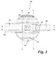
- the main body 102 also comprises a motor and fan arrangement (not shown) downstream of the separating apparatus 116 and an air outlet 120 (best shown in Figure 3 ) for exhausting air from the main body 102.
- An airflow path through the hand-held vacuum cleaner 100 extends from the suction inlet 108, through the suction nozzle 104, the separating apparatus 116, the motor and fan arrangement and to the air outlet 120 where the airflow is exhausted from the main body 102 of the hand-held vacuum cleaner 100.
- a power source (not shown) for powering the motor and fan arrangement is also located within the main body 102.
- the power source takes the form of a group of batteries located within the main body 102. It is generally useful for a hand-held cleaning appliance to be battery powered to enable cleaning of a wide range of surfaces and locations.
- the hand-held vacuum cleaner 100 may be powered by another source; for example, mains electricity or an in-car charger connection.
- the mechanism for enabling movement of the suction nozzle 104 and handle 106 will now be described with reference to Figures 5 to 7 .
- the suction nozzle 104 is pivotably connected to the main body 102 by means of a pivot 122 and is pivotable between the stored position and the in-use position about an axis X-X passing through the pivot 122 (this is also shown in Figures 3 and 4 ).
- the handle 106 is pivotably connected to the main body 102 by means of a pivot 124 and is pivotable between the stored position and the in-use position about an axis Y-Y passing through the pivot 124 (this is also shown in Figure 3 and 4 ).
- the axes X-X and Y-Y are parallel to one another, although this need not be the case.
- a linkage arrangement 126 is connected directly between the suction nozzle 104 and the handle 106. In other words, the linkage arrangement 126 is not directly connected to the main body 102 and is essentially movable independently thereof.
- the linkage arrangement 126 comprises a linkage member 128 having a first portion 130 and a second portion 132.
- the first portion 130 is connected to the suction nozzle 104 about a first linkage connection 134.
- the first linkage connection 134 comprises a pivotable connection which enables the linkage member 128 to rotate about an axis L1 with respect to the suction nozzle 104.
- the first linkage connection 134 is radially spaced from the axis X-X (and, thus, from the pivot 122) as will be described later. Therefore, the axes X-X and L1 are parallel to one another and spaced apart.
- the second portion 132 is connected to the handle 106 about a second linkage connection 136.
- the second linkage connection 136 comprises a pivotable connection which enables the linkage member 128 to rotate about an axis L2 with respect to the handle 106.
- the second linkage connection 134 is radially spaced from the axis Y-Y (and, thus, from the pivot 124) as will be described later. Therefore, the axes Y-Y and L2 are parallel to one another and spaced apart.
- axes X-X, Y-Y, L1 and L2 all lie substantially parallel to one another, although this need not be so.
- the linkage arrangement 126 enables the suction nozzle 104 and handle 106 to be movable together.
- the linkage arrangement 126 is configured such that movement of one of the suction nozzle 104 and the handle 106 causes a corresponding coupled movement of the other of the suction nozzle 104 and handle 106.
- This enables a user to, for example, move the handle 106 from the stored position to the in-use position (or vice versa) and cause a corresponding movement of the suction nozzle 104. Therefore, the hand-held vacuum cleaner 100 can be readied for use (or, alternatively, be placed in the storage configuration) with a single movement. This is convenient for the user.
- One aspect of this is effected by the connection of the linkage member 128 between the handle 106 and the suction nozzle 104 at points which are radially spaced from the pivot axes X-X, Y-Y.
- This will result in a corresponding moment on the suction nozzle 104 about the axis Y-Y (resulting from the location of the second linkage connection 134) and, as a result, the suction nozzle 104 will be caused to move.
- the linkage arrangement 126 is configured to bias the suction nozzle 104 and handle 106 into one of the stored or in-use positions.
- the suction nozzle 104 and handle 106 are biased into the stored position.
- the linkage arrangement 126 comprises a resilient member 138 in the form of a coil spring which extends between a part of the linkage member 128 and the main body 102.
- the linkage member 128 will move generally downwards (with respect to Figure 5 ). Therefore, the coil spring 138 is placed under tension.
- the coil spring 138 applies a force on the linkage member 128 to draw the linkage member 128 in a generally upwards direction (relative to Figure 5 ). This force will act to move the suction nozzle 104 and handle 106 back into the stored position.
- a catch arrangement 140 is provided.
- the catch arrangement 140 comprises a linearly movable catch arm 142 having a projection 144 operable to engage with a complementary recess 146 formed in the surface of a cylinder 147 located on the handle 106.
- the cylinder 146 is located about the axis Y-Y.
- the catch arm 142 is biased upwardly (relative to Figure 5 ) by a spring (not shown) such that, when the handle 106 (and suction nozzle 104) are extended fully into the in-use position, the projection 144 engages with the recess 146 to retain (or lock) the handle 106 and suction nozzle 104 in the in-use position.
- the catch arrangement 140 further comprises a user-operable button 148 at an upper end of the catch arm 142.
- the button 148 is depressable by a user against the biasing force of the spring such that depression of the button 148 moves the projection 144 away from the recess 146 and releases the suction nozzle 104 and handle 106 from the in-use position.
- the biasing force of the coil spring 138 acting on the linkage member 128 will cause both of the suction nozzle 104 and the handle 106 to move to their respective stored positions.
- the nature of this transition (e.g. the speed of the transition) can be adjusted by adjusting the spring force of the coil spring 138.
- the first and second portions 130, 132 are movable with respect to one another and releasably retained with respect to one another by a retaining arrangement 150.
- the first portion 130 is arranged to slide within the second portion 132. This can be seen by a comparison of Figures 5 and 6 (where Figure 6 shows the first and second portions 130, 132 having been slid within one another).
- the retaining arrangement 150 is provided to prevent the first and second portions 130, 132 from sliding with respect to one another unless a particular force (an "abuse force") is applied across the linkage member 128.
- the retaining arrangement 150 comprises a pair of projections 152 formed on the first portion 130 which engage with a pair of complementary recesses 154 formed in the second portion 132.
- the projections 152 and recesses 154 are held in place by friction and the shape of the respective parts. Therefore, the retaining arrangement 150 will only release to enable the first and second portions 130, 132 to move relative thereto when the applied abuse force exceeds the force required to deform the material (in this case, nylon or plastic) of the first and second portions 130, 132 such that the projections 152 can move out of the recesses 154 to enable slideable movement between the first and second portions 130, 132. Slideable movement of the first and second portions 130, 132 prevents breakage of the linkage member 128 when an abuse force is applied.
- the retaining arrangement 150 further comprises a resilient member 156 in the form of a coil compression spring.
- the spring 156 applies a force along the length of the linkage member 128 to bias the first and second portions 130, 132 towards the retained position (as shown in Figure 5 ).
- the spring 156 can also be used to assist the material force of the projection 152/recess 154 connection and provide a high abuse force to prevent accidental tripping of the mechanism. This also provides a mechanism for accurate fine tuning of the abuse force threshold because a spring force is more readily adjustable than structural material properties.
- the hand-held vacuum cleaner 100 In use, the hand-held vacuum cleaner 100 is likely to be initially in the stored configuration as shown in Figure 2 . Therefore, the user will lift one of the handle 106 or suction nozzle 104 upwards to bring the hand-held vacuum cleaner 100 into the in-use configuration. Due to the linkage arrangement 126, movement of one of the handle 106 or the suction nozzle 104 will cause a corresponding movement of the other element, which is convenient for a user because the hand-held vacuum cleaner 100 can be placed in the in-use configuration with one movement.
- the projection 144 of the catch arrangement 140 will engage with the recess 146 of the cylinder 147 and will retain the handle 106 and suction nozzle 104 in the in-use positions. In other words, the hand-held vacuum cleaner 100 is now ready for use.
- the user can then press the power switch 110 to operate the motor and fan unit to draw a flow of dirt- and debris-laden air into the suction inlet 108, through the suction nozzle 104 and into the separating apparatus 116 where the dirt and debris is collected.
- the air then passes through the motor and fan unit and is exhausted from the main body 102 through the air outlet 116.
- the hand-held vacuum cleaner 100 can be returned to the storage configuration shown in Figure 2 for convenient and compact storage. This is done by the user pressing on the button 148 which releases the projection 144 from the recess 146. The suction nozzle 104 and handle 106 will then be urged back to the stored positions under the bias of the restoring force of the coil spring 138. This restoring force also maintains the suction nozzle 104 and handle 106 in the respective stored positions. In other words, the coil spring 138 biases the suction nozzle 104 and handle 106 against the main body 102; for example, should the user invert the hand-held vacuum cleaner 100 when in the stored configuration.
- the handle and suction nozzle may not be pivotable and may be movable in different configurations, e.g. through the use of a cam or sliding connection. Further, the handle and suction nozzle may be biased into the in-use position, and retained in the stored position.
- linkage member need not comprise two sections and may instead comprise a single section.
- the present invention is not limited to hand-held vacuum cleaners.
- portable cleaning appliance could be used, for example, carpet shampooers, wet and dry machines or blower vacuum devices.
Landscapes
- Engineering & Computer Science (AREA)
- Mechanical Engineering (AREA)
- Electric Vacuum Cleaner (AREA)
- Body Washing Hand Wipes And Brushes (AREA)
Abstract
Description
- The present invention relates to a portable cleaning appliance. More particularly, the present invention relates to a cleaning appliance comprising a nozzle and a graspable handle, each of which is movable between a retracted and an in-use position.
- A known type of portable cleaning appliance is a hand-held vacuum cleaner. A common type is that manufactured by Black and Decker ™ under the registered trade mark Dustbuster ™. Such a hand-held vacuum cleaner has a main body with a suction inlet at a distal end thereof. A suction nozzle extends from the suction inlet to a dust bag for separating dirt and dust from an airflow. A motor and fan arrangement is also provided in the main body together with a power source. A graspable handle is generally located at the rear of the main body.
- An alternative configuration of hand-held vacuum cleaner is that manufactured by Black and Decker™ under the registered trade mark Dustbuster™ Pivot ™. Such a hand-held vacuum cleaner comprises a main body including a fixed graspable handle. A suction inlet is located at a distal end of a suction nozzle which leads to separating apparatus such as a cyclonic separator. In this arrangement, the suction nozzle is operable to pivot with respect to the main body so that the suction nozzle can be moved between a stored position and a position in which it can be used to clean a surface.
- According to an aspect of the present invention, there is provided a portable cleaning appliance comprising a main body, a nozzle and a graspable handle, the nozzle and handle each being movable relative to the main body between a first, storage, position adjacent the main body and a second, in-use, position in which the nozzle and handle extend from the main body, wherein the nozzle and handle are connected by a linkage member arranged such that, in use, movement of one of the nozzle and the handle between the first and second positions causes a corresponding coupled movement of the other of the nozzle and handle between the first and second positions.
- By providing such an arrangement, both the nozzle and handle can be extended or retracted with a single movement of one of those elements. This results in a convenient and smooth operation for a user and a smooth and fast transition between the stored and in-use positions.
- In one embodiment, the nozzle and the handle are each pivotally connected to the main body about a respective axis of rotation. A pivotable connection is robust, mechanically efficient and provides smooth movement of the respective components.
- In one embodiment, the linkage member is connected directly between the nozzle and the handle at points radially spaced from each respective axis of rotation. This arrangement enables an appropriate moment to be applied to each of the nozzle and handle to assist in the coupled motion therebetween.
- In one embodiment, the cleaning appliance further comprises a user-operable catch arrangement operable to lock releasably the nozzle and handle in at least one of the first and second positions. By providing a catch arrangement, the nozzle and handle can be retained in an in-use configuration for cleaning without additional input from a user, or retained in a stored configuration for robustness.
- In one embodiment, a resilient member is connected between the linkage member and the main body and arranged to bias the nozzle and handle towards one of the first and second positions when the catch arrangement is released. By providing such an arrangement, the nozzle and handle are urged towards one of the configurations, assisting the user in the transition therebetween.
- In one embodiment, the linkage member comprises first and second portions releasably retained in a retained position with respect to one another by a retaining arrangement. By providing such a releasable connection between the parts of the linkage member, an excessive force applied across the linkage member will cause the parts of the linkage member to move with respect to one another rather than undergo breakage.
- In one embodiment, the retaining arrangement comprising a first retaining element located on one of the first and second portions and a complementary second retaining element located on the other of the first and second portions. This arrangement enables the first and second portions to be reliably held with respect to one another.
- In one embodiment, said first retaining element comprises a recess and the second retaining element comprises a projection engageable with the recess. This configuration is mechanically strong, straightforward to manufacture and robust.
- In one embodiment, the retaining arrangement is operable to release the first and second portions from the retained position to enable relative movement therebetween when a force applied between the first and second portions exceeds a pre-determined threshold. This configuration provides a pre-determined "abuse force" above which the parts move with respect to one another to prevent damage.
- In one embodiment, the first and second portions are slideable with respect to one another once released. This is a convenient arrangement which enables the elements to be easily returned to their original positions.
- In one embodiment, one of said first and second portions is slideable within the other of said first and second portions. This is a compact and robust arrangement.
- In one embodiment, the linkage member further comprises a resilient member arranged to urge the first and second portions towards the retained position. This assists in returning the parts to the retained position once an abuse force has been applied.
- In one embodiment, the nozzle and handle are at least partially recessed in the main body when in the first position. This provides a compact, robust and aesthetically pleasing appearance.
- In one embodiment, at least parts of the nozzle and handle lie substantially flush with the main body when in the first position. This enables the cleaning appliance to be provided in a range of shapes and configurations, and is more resistant to damage.
- In one embodiment, the cleaning appliance is in the form of a hand-held vacuum cleaner comprising a suction inlet located at a distal end of the nozzle and separating apparatus located downstream of the suction inlet for separating dirt and debris from an airflow drawn in through the suction inlet.
- Embodiments of the present invention will now be described in detail with reference to the accompanying drawings, in which:
-
Figure 1 is a perspective view showing a hand-held vacuum cleaner according to an embodiment of the present invention in an in-use configuration; -
Figure 2 is a perspective view of the hand-held vacuum cleaner ofFigure 1 in a stored configuration; -
Figure 3 is a plan view of the hand-held vacuum cleaner ofFigure 1 in the in-use configuration; -
Figure 4 is side view of the hand-held vacuum cleaner ofFigure 1 in the in-use configuration; -
Figure 5 is a cross-sectional side view, taken along the line A-A ofFigure 3 , illustrating a linkage arrangement forming part the hand-held vacuum cleaner ofFigure 1 in a retained configuration; -
Figure 6 is a cross-sectional side view, taken along the line A-A ofFigure 3 , of the hand-held vacuum cleaner ofFigure 1 illustrating the linkage arrangement in a released configuration; and -
Figure 7 is an alternative cross-sectional side view of the hand-held vacuum cleaner ofFigure 1 in the stored configuration showing the linkage arrangement in the retained configuration. - The present invention provides a portable cleaning appliance which is operable to provide both a graspable handle and a suction nozzle which are movable between a stored position in which the cleaning appliance is more compact and robust than known arrangements, and an in-use position in which the cleaning appliance can be manipulated comfortably by a user. Further, the present invention provides an intuitive operation mechanism to enable an efficient, easy to use and reliable transition between the stored and in-use positions.
-
Figures 1 to 4 show a hand-heldvacuum cleaner 100. The hand-heldvacuum cleaner 100 comprises amain body 102 to which asuction nozzle 104 and agraspable handle 106 are attached. Thesuction nozzle 104 comprises asuction inlet 108 at a distal end thereof. - The
handle 106 is dimensioned to fit a user's hand and arranged to enable the hand-heldvacuum cleaner 100 to be manipulated in use. Thehandle 106 includes apower switch 110 which enables a user to switch the hand-heldvacuum cleaner 100 on and off. Thepower switch 110 is positioned such that a user can operate thepower switch 110 with the thumb of the hand with which the hand-heldvacuum cleaner 100 is being grasped. - The
suction nozzle 104 andhandle 106 are movable between stored and in-use positions.Figures 1 ,3 and4 show the hand-heldvacuum cleaner 100 in an in-use configuration in which each of thesuction nozzle 104 and thehandle 106 is in an extended, in-use position.Figure 2 shows the hand-heldvacuum cleaner 100 in a stored configuration in which each of thesuction nozzle 104 and thehandle 106 is in a retracted, storage position. - The
suction nozzle 104 andhandle 106 are shaped such that, when thesuction nozzle 104 andhandle 106 are each in the stored position (as shown inFigure 2 ), thesuction nozzle 104 and handle 106 substantially conform to the shape of themain body 102 to provide a robust and compact configuration for storage, and a pleasing appearance for the user. In this regard, themain body 102 comprisesrecesses respective suction nozzle 104 and handle 106 such that thesuction nozzle 104 andhandle 106 are at least partially recessed into themain body 102. Further, parts of thesuction nozzle 104 and handle 106 lie substantially flush with themain body 102. - The
main body 102 comprises separatingapparatus 116 for separating dirt and debris from an airflow drawn in through thesuction inlet 108. The separatingapparatus 116 is in fluid communication with thesuction inlet 108 through the interior of thesuction nozzle 104. The separatingapparatus 116 may comprise any suitable separation arrangement; for example, an inertial separator, a mechanical filter, a porous bag, a cyclonic separator or a combination thereof. - The separating
apparatus 116 is operable to collect separated dirt and debris within the interior of themain body 102. In this regard, the separatingapparatus 116 comprises amovable cover 118 which is openable to facilitate emptying of collected dirt and debris from the separatingapparatus 116. - The
main body 102 also comprises a motor and fan arrangement (not shown) downstream of theseparating apparatus 116 and an air outlet 120 (best shown inFigure 3 ) for exhausting air from themain body 102. An airflow path through the hand-heldvacuum cleaner 100 extends from thesuction inlet 108, through thesuction nozzle 104, the separatingapparatus 116, the motor and fan arrangement and to theair outlet 120 where the airflow is exhausted from themain body 102 of the hand-heldvacuum cleaner 100. - A power source (not shown) for powering the motor and fan arrangement is also located within the
main body 102. In this embodiment, the power source takes the form of a group of batteries located within themain body 102. It is generally useful for a hand-held cleaning appliance to be battery powered to enable cleaning of a wide range of surfaces and locations. However, in the alternative, the hand-heldvacuum cleaner 100 may be powered by another source; for example, mains electricity or an in-car charger connection. - The mechanism for enabling movement of the
suction nozzle 104 and handle 106 will now be described with reference toFigures 5 to 7 . Thesuction nozzle 104 is pivotably connected to themain body 102 by means of apivot 122 and is pivotable between the stored position and the in-use position about an axis X-X passing through the pivot 122 (this is also shown inFigures 3 and4 ). - Concomitantly, the
handle 106 is pivotably connected to themain body 102 by means of apivot 124 and is pivotable between the stored position and the in-use position about an axis Y-Y passing through the pivot 124 (this is also shown inFigure 3 and4 ). In this embodiment, the axes X-X and Y-Y are parallel to one another, although this need not be the case. - A
linkage arrangement 126 is connected directly between thesuction nozzle 104 and thehandle 106. In other words, thelinkage arrangement 126 is not directly connected to themain body 102 and is essentially movable independently thereof. - The
linkage arrangement 126 comprises alinkage member 128 having afirst portion 130 and asecond portion 132. Thefirst portion 130 is connected to thesuction nozzle 104 about afirst linkage connection 134. Thefirst linkage connection 134 comprises a pivotable connection which enables thelinkage member 128 to rotate about an axis L1 with respect to thesuction nozzle 104. Thefirst linkage connection 134 is radially spaced from the axis X-X (and, thus, from the pivot 122) as will be described later. Therefore, the axes X-X and L1 are parallel to one another and spaced apart. - The
second portion 132 is connected to thehandle 106 about asecond linkage connection 136. Thesecond linkage connection 136 comprises a pivotable connection which enables thelinkage member 128 to rotate about an axis L2 with respect to thehandle 106. Thesecond linkage connection 134 is radially spaced from the axis Y-Y (and, thus, from the pivot 124) as will be described later. Therefore, the axes Y-Y and L2 are parallel to one another and spaced apart. - In this embodiment, axes X-X, Y-Y, L1 and L2 all lie substantially parallel to one another, although this need not be so.
- The
linkage arrangement 126 enables thesuction nozzle 104 and handle 106 to be movable together. In other words, thelinkage arrangement 126 is configured such that movement of one of thesuction nozzle 104 and thehandle 106 causes a corresponding coupled movement of the other of thesuction nozzle 104 and handle 106. This enables a user to, for example, move thehandle 106 from the stored position to the in-use position (or vice versa) and cause a corresponding movement of thesuction nozzle 104. Therefore, the hand-heldvacuum cleaner 100 can be readied for use (or, alternatively, be placed in the storage configuration) with a single movement. This is convenient for the user. - One aspect of this is effected by the connection of the
linkage member 128 between thehandle 106 and thesuction nozzle 104 at points which are radially spaced from the pivot axes X-X, Y-Y. This means that, upon movement of, for example, thehandle 106, a moment between thesecond linkage connection 136 and thepivot 124 will result, causing thelinkage member 128 to move with respect to themain body 102. This will result in a corresponding moment on thesuction nozzle 104 about the axis Y-Y (resulting from the location of the second linkage connection 134) and, as a result, thesuction nozzle 104 will be caused to move. - In order to provide greater convenience for a user, the
linkage arrangement 126 is configured to bias thesuction nozzle 104 and handle 106 into one of the stored or in-use positions. In this embodiment, thesuction nozzle 104 and handle 106 are biased into the stored position. However, it is equally possible to bias these elements into the in-use position. - In this regard, the
linkage arrangement 126 comprises aresilient member 138 in the form of a coil spring which extends between a part of thelinkage member 128 and themain body 102. When thesuction nozzle 104 and handle 106 are moved into the in-use positions (as shown inFigure 5 ), thelinkage member 128 will move generally downwards (with respect toFigure 5 ). Therefore, thecoil spring 138 is placed under tension. - As a result, in this configuration, the
coil spring 138 applies a force on thelinkage member 128 to draw thelinkage member 128 in a generally upwards direction (relative toFigure 5 ). This force will act to move thesuction nozzle 104 and handle 106 back into the stored position. - In order to retain the
suction nozzle 104 and handle 106 in the in-use position so that a user can use the hand-heldvacuum cleaner 100, acatch arrangement 140 is provided. Thecatch arrangement 140 comprises a linearlymovable catch arm 142 having aprojection 144 operable to engage with acomplementary recess 146 formed in the surface of acylinder 147 located on thehandle 106. Thecylinder 146 is located about the axis Y-Y. - The
catch arm 142 is biased upwardly (relative toFigure 5 ) by a spring (not shown) such that, when the handle 106 (and suction nozzle 104) are extended fully into the in-use position, theprojection 144 engages with therecess 146 to retain (or lock) thehandle 106 andsuction nozzle 104 in the in-use position. - The
catch arrangement 140 further comprises a user-operable button 148 at an upper end of thecatch arm 142. The button 148 is depressable by a user against the biasing force of the spring such that depression of the button 148 moves theprojection 144 away from therecess 146 and releases thesuction nozzle 104 and handle 106 from the in-use position. When this is done, the biasing force of thecoil spring 138 acting on thelinkage member 128 will cause both of thesuction nozzle 104 and thehandle 106 to move to their respective stored positions. The nature of this transition (e.g. the speed of the transition) can be adjusted by adjusting the spring force of thecoil spring 138. - There is the possibility that a user may attempt to force one of the
suction nozzle 104 or handle 106 down whilst the other of those elements is still retained. This may occur, for example, when the user has not realised that the button 148 is required to be depressed and may attempt to force down thesuction nozzle 104 back to the stored position. Such an application of force may lead to damage to thelinkage member 128 which will experience a compressive force. - In order to reduce the risk of damage to the
linkage arrangement 126 and, particularly, thelinkage member 128, the first andsecond portions arrangement 150. - The
first portion 130 is arranged to slide within thesecond portion 132. This can be seen by a comparison ofFigures 5 and6 (whereFigure 6 shows the first andsecond portions - The retaining
arrangement 150 is provided to prevent the first andsecond portions linkage member 128. The retainingarrangement 150 comprises a pair ofprojections 152 formed on thefirst portion 130 which engage with a pair ofcomplementary recesses 154 formed in thesecond portion 132. - The
projections 152 and recesses 154 are held in place by friction and the shape of the respective parts. Therefore, the retainingarrangement 150 will only release to enable the first andsecond portions second portions projections 152 can move out of therecesses 154 to enable slideable movement between the first andsecond portions second portions linkage member 128 when an abuse force is applied. - In order to assist in the return of the first and
second portions arrangement 150 further comprises aresilient member 156 in the form of a coil compression spring. Thespring 156 applies a force along the length of thelinkage member 128 to bias the first andsecond portions Figure 5 ). - The
spring 156 can also be used to assist the material force of theprojection 152/recess 154 connection and provide a high abuse force to prevent accidental tripping of the mechanism. This also provides a mechanism for accurate fine tuning of the abuse force threshold because a spring force is more readily adjustable than structural material properties. - In use, the hand-held
vacuum cleaner 100 is likely to be initially in the stored configuration as shown inFigure 2 . Therefore, the user will lift one of thehandle 106 orsuction nozzle 104 upwards to bring the hand-heldvacuum cleaner 100 into the in-use configuration. Due to thelinkage arrangement 126, movement of one of thehandle 106 or thesuction nozzle 104 will cause a corresponding movement of the other element, which is convenient for a user because the hand-heldvacuum cleaner 100 can be placed in the in-use configuration with one movement. - When the
handle 106 andsuction nozzle 104 are fully extended into the in-use positions, theprojection 144 of thecatch arrangement 140 will engage with therecess 146 of thecylinder 147 and will retain thehandle 106 andsuction nozzle 104 in the in-use positions. In other words, the hand-heldvacuum cleaner 100 is now ready for use. - The user can then press the
power switch 110 to operate the motor and fan unit to draw a flow of dirt- and debris-laden air into thesuction inlet 108, through thesuction nozzle 104 and into the separatingapparatus 116 where the dirt and debris is collected. The air then passes through the motor and fan unit and is exhausted from themain body 102 through theair outlet 116. - When a user has completed a cleaning task, the hand-held
vacuum cleaner 100 can be returned to the storage configuration shown inFigure 2 for convenient and compact storage. This is done by the user pressing on the button 148 which releases theprojection 144 from therecess 146. Thesuction nozzle 104 and handle 106 will then be urged back to the stored positions under the bias of the restoring force of thecoil spring 138. This restoring force also maintains thesuction nozzle 104 and handle 106 in the respective stored positions. In other words, thecoil spring 138 biases thesuction nozzle 104 and handle 106 against themain body 102; for example, should the user invert the hand-heldvacuum cleaner 100 when in the stored configuration. - Variations of the above embodiments will be apparent to the skilled person. The precise configuration of components may differ and still fall within the scope of the present invention.
- For example, the handle and suction nozzle may not be pivotable and may be movable in different configurations, e.g. through the use of a cam or sliding connection. Further, the handle and suction nozzle may be biased into the in-use position, and retained in the stored position.
- Additionally, the linkage member need not comprise two sections and may instead comprise a single section.
- Further, the present invention is not limited to hand-held vacuum cleaners. Other types of portable cleaning appliance could be used, for example, carpet shampooers, wet and dry machines or blower vacuum devices.
- Embodiments of the present invention have been described with particular reference to the examples illustrated. While specific examples are shown in the drawings and are herein described in detail, it should be understood, however, that the drawings and detailed description are not intended to limit the invention to the particular form disclosed. It will be appreciated that variations and modifications may be made to the examples described within the scope of the present invention.
Claims (14)
- A portable cleaning appliance comprising a main body, a nozzle and a graspable handle, the nozzle and handle each being movable relative to the main body between a first, storage, position adjacent the main body and a second, in-use, position in which the nozzle and handle extend from the main body, wherein the nozzle and handle are connected by a linkage member arranged such that, in use, movement of one of the nozzle and the handle between the first and second positions causes a corresponding coupled movement of the other of the nozzle and handle between the first and second positions.
- A cleaning appliance according to claim 1, wherein the nozzle and the handle are each pivotally connected to the main body about a respective axis of rotation.
- A cleaning appliance according to claim 2, wherein the linkage member is connected directly between the nozzle and the handle at points radially spaced from each respective axis of rotation.
- A cleaning appliance according to any one of the preceding claims, further comprising a user-operable catch arrangement operable to lock releasably the nozzle and handle in at least one of the first and second positions.
- A cleaning appliance according to claim 4, wherein a resilient member is connected between the linkage member and the main body and arranged to bias the nozzle and handle towards one of the first and second positions when the catch arrangement is released.
- A cleaning appliance according to any one of the preceding claims, wherein the linkage member comprises first and second portions releasably retained in a retained position with respect to one another by a retaining arrangement.
- A cleaning appliance according to claim 6, wherein the retaining arrangement comprising a first retaining element located on one of the first and second portions and a complementary second retaining element located on the other of the first and second portions.
- A cleaning appliance according to claim 7, wherein said first retaining element comprises a recess and the second retaining element comprises a projection engageable with the recess.
- A cleaning appliance according to claim 6, 7 or 8, wherein the retaining arrangement is operable to release the first and second portions from the retained position to enable relative movement therebetween when a force applied between the first and second portions exceeds a pre-determined threshold.
- A cleaning appliance according to claim 9, wherein the first and second portions are slideable with respect to one another once released.
- A cleaning appliance according to claim 10, wherein one of said first and second portions is slideable within the other of said first and second portions.
- A cleaning appliance according to claim 6 to 11, wherein the linkage member further comprises a resilient member arranged to urge the first and second portions towards the retained position.
- A cleaning appliance according to any one of the preceding claims, wherein the nozzle and handle are at least partially recessed in the main body when in the first position.
- A cleaning appliance according to any one of the preceding claims in the form of a hand-held vacuum cleaner comprising a suction inlet located at a distal end of the nozzle and separating apparatus located downstream of the suction inlet for separating dirt and debris from an airflow drawn in through the suction inlet.
Priority Applications (6)
| Application Number | Priority Date | Filing Date | Title |
|---|---|---|---|
| EP11168516.0A EP2529652B1 (en) | 2011-06-01 | 2011-06-01 | A cleaning appliance |
| AU2012203208A AU2012203208B2 (en) | 2011-06-01 | 2012-05-28 | A cleaning appliance |
| JP2012121977A JP5894011B2 (en) | 2011-06-01 | 2012-05-29 | Cleaning device |
| CA2778511A CA2778511C (en) | 2011-06-01 | 2012-05-29 | A cleaning appliance |
| CN201210175011.4A CN102805593B (en) | 2011-06-01 | 2012-05-30 | A cleaning appliance |
| US13/484,955 US8607412B2 (en) | 2011-06-01 | 2012-05-31 | Cleaning appliance |
Applications Claiming Priority (1)
| Application Number | Priority Date | Filing Date | Title |
|---|---|---|---|
| EP11168516.0A EP2529652B1 (en) | 2011-06-01 | 2011-06-01 | A cleaning appliance |
Publications (2)
| Publication Number | Publication Date |
|---|---|
| EP2529652A1 true EP2529652A1 (en) | 2012-12-05 |
| EP2529652B1 EP2529652B1 (en) | 2016-03-16 |
Family
ID=44118157
Family Applications (1)
| Application Number | Title | Priority Date | Filing Date |
|---|---|---|---|
| EP11168516.0A Not-in-force EP2529652B1 (en) | 2011-06-01 | 2011-06-01 | A cleaning appliance |
Country Status (6)
| Country | Link |
|---|---|
| US (1) | US8607412B2 (en) |
| EP (1) | EP2529652B1 (en) |
| JP (1) | JP5894011B2 (en) |
| CN (1) | CN102805593B (en) |
| AU (1) | AU2012203208B2 (en) |
| CA (1) | CA2778511C (en) |
Cited By (2)
| Publication number | Priority date | Publication date | Assignee | Title |
|---|---|---|---|---|
| EP2818088A1 (en) * | 2013-06-24 | 2014-12-31 | Bukang Sems Co., Ltd. | Vacuum cleaner |
| WO2021170988A1 (en) * | 2020-02-26 | 2021-09-02 | Techtronic Cordless Gp | Concealed handle on cleaning device |
Families Citing this family (39)
| Publication number | Priority date | Publication date | Assignee | Title |
|---|---|---|---|---|
| US20210401246A1 (en) | 2016-04-11 | 2021-12-30 | Omachron Intellectual Property Inc. | Surface cleaning apparatus |
| US10258208B2 (en) | 2016-04-11 | 2019-04-16 | Omachron Intellectual Property Inc. | Surface cleaning apparatus |
| WO2010102394A1 (en) | 2009-03-11 | 2010-09-16 | G.B.D. Corp. | Hand vacuum cleaner with removable dirt chamber |
| US10722086B2 (en) | 2017-07-06 | 2020-07-28 | Omachron Intellectual Property Inc. | Handheld surface cleaning apparatus |
| US10674884B2 (en) | 2013-02-28 | 2020-06-09 | Omachron Intellectual Property Inc. | Hand carryable surface cleaning apparatus |
| US20140237764A1 (en) | 2013-02-28 | 2014-08-28 | G.B.D. Corp. | Cyclone such as for use in a surface cleaning apparatus |
| US10729294B2 (en) | 2013-02-28 | 2020-08-04 | Omachron Intellectual Property Inc. | Hand carryable surface cleaning apparatus |
| US9775484B2 (en) * | 2013-03-01 | 2017-10-03 | Omachron Intellectual Property Inc. | Surface cleaning apparatus |
| US10791889B2 (en) | 2016-01-08 | 2020-10-06 | Omachron Intellectual Property Inc. | Hand carryable surface cleaning apparatus |
| US10022027B2 (en) | 2014-12-17 | 2018-07-17 | Omachron Intellectual Property Inc. | All in the head surface cleaning apparatus |
| US9883781B2 (en) | 2014-12-17 | 2018-02-06 | Omachron Intellectual Property Inc. | All in the head surface cleaning apparatus |
| US11950745B2 (en) | 2014-12-17 | 2024-04-09 | Omachron Intellectual Property Inc. | Surface cleaning apparatus |
| US10064530B2 (en) | 2015-09-16 | 2018-09-04 | Bissell Homecare, Inc. | Handheld vacuum cleaner |
| US12390062B2 (en) | 2016-01-08 | 2025-08-19 | Omachron Intellectual Property Inc. | Hand carryable surface cleaning apparatus |
| US9962048B2 (en) | 2016-01-08 | 2018-05-08 | Omachron Intellectual Property | Hand carryable surface cleaning apparatus |
| US10426302B2 (en) | 2016-01-08 | 2019-10-01 | Omachron Intellectual Property Inc. | Hand carryable surface cleaning apparatus |
| US10165914B2 (en) | 2016-01-08 | 2019-01-01 | Omachron Intellectual Property Inc. | Hand carryable surface cleaning apparatus |
| US11918170B2 (en) | 2016-04-11 | 2024-03-05 | Omachron Intellectual Property Inc. | Surface cleaning apparatus |
| US11241129B2 (en) | 2016-04-11 | 2022-02-08 | Omachron Intellectual Property Inc. | Surface cleaning apparatus |
| US10016105B2 (en) | 2016-04-11 | 2018-07-10 | Omachron Intellectual Property Inc. | Surface cleaning apparatus |
| US10016104B2 (en) | 2016-04-11 | 2018-07-10 | Omachron Intellectual Property Inc. | Surface cleaning apparatus |
| US10568477B2 (en) | 2016-04-11 | 2020-02-25 | Omachron Intellectual Property Inc. | Surface cleaning apparatus |
| US9986880B2 (en) | 2016-04-11 | 2018-06-05 | Omachron Intellectual Property Inc. | Surface cleaning apparatus |
| USD829394S1 (en) * | 2016-06-15 | 2018-09-25 | Samsung Electronics Co., Ltd. | Body for vacuum cleaner |
| USD829395S1 (en) * | 2016-06-15 | 2018-09-25 | Samsung Electronics Co., Ltd. | Body for vacuum cleaner |
| US10842330B2 (en) | 2017-07-06 | 2020-11-24 | Omachron Intellectual Property Inc. | Handheld surface cleaning apparatus |
| US10702113B2 (en) | 2017-07-06 | 2020-07-07 | Omachron Intellectual Property Inc. | Handheld surface cleaning apparatus |
| US10750913B2 (en) | 2017-07-06 | 2020-08-25 | Omachron Intellectual Property Inc. | Handheld surface cleaning apparatus |
| US10631693B2 (en) | 2017-07-06 | 2020-04-28 | Omachron Intellectual Property Inc. | Handheld surface cleaning apparatus |
| US10506904B2 (en) | 2017-07-06 | 2019-12-17 | Omachron Intellectual Property Inc. | Handheld surface cleaning apparatus |
| US10537216B2 (en) | 2017-07-06 | 2020-01-21 | Omachron Intellectual Property Inc. | Handheld surface cleaning apparatus |
| KR101992018B1 (en) * | 2017-09-19 | 2019-09-30 | 에이스전자(주) | A foldable vacuum cleaner |
| US11930987B2 (en) | 2018-04-20 | 2024-03-19 | Omachron Intellectual Property Inc. | Surface cleaning apparatus |
| US10932634B2 (en) | 2018-05-30 | 2021-03-02 | Omachron Intellectual Property Inc. | Surface cleaning apparatus |
| US10827889B2 (en) | 2018-05-30 | 2020-11-10 | Omachron Intellectual Property Inc. | Surface cleaning apparatus |
| US11612290B2 (en) | 2019-06-05 | 2023-03-28 | Omachron Intellectual Property Inc. | Surface cleaning apparatus |
| CN110881896A (en) * | 2019-12-17 | 2020-03-17 | 安徽冠东科技有限公司 | Annular cavity type handheld dust collector |
| KR102314321B1 (en) * | 2020-01-10 | 2021-10-19 | 엘지전자 주식회사 | Cleaner |
| CN111728529A (en) * | 2020-06-16 | 2020-10-02 | 苏州凯弘橡塑有限公司 | Multifunctional portable sterilization acarus killing device |
Citations (3)
| Publication number | Priority date | Publication date | Assignee | Title |
|---|---|---|---|---|
| DE3309162A1 (en) * | 1983-03-15 | 1984-09-20 | Krups Stiftung | Battery-operated table vacuum cleaner |
| CN201398936Y (en) * | 2009-04-01 | 2010-02-10 | 苏州凯丽达电器有限公司 | Hand-held vacuum cleaner |
| CN201624601U (en) * | 2009-12-18 | 2010-11-10 | 耀川电子(深圳)有限公司 | Hand-hold dust collector with fast-turning folding long suction nozzle |
Family Cites Families (11)
| Publication number | Priority date | Publication date | Assignee | Title |
|---|---|---|---|---|
| JPS62142532A (en) * | 1985-12-17 | 1987-06-25 | 松下電器産業株式会社 | rechargeable vacuum cleaner |
| JPS62204544U (en) * | 1986-06-19 | 1987-12-26 | ||
| JPH01128741U (en) * | 1988-02-24 | 1989-09-01 | ||
| JP2594238Y2 (en) * | 1992-05-13 | 1999-04-26 | 三洋電機株式会社 | Handy cleaner |
| TW271384B (en) * | 1995-01-13 | 1996-03-01 | Black & Decker Inc | Vacuum cleaner |
| JP3081983U (en) * | 2001-05-22 | 2001-11-22 | 株式会社高敏 | Upright vacuum cleaner |
| JP2005058246A (en) * | 2003-08-08 | 2005-03-10 | Hitachi Home & Life Solutions Inc | Dishwasher |
| CN101262807B (en) * | 2005-01-18 | 2011-11-16 | 伊莱克斯家用产品有限公司 | Vacuum cleaner with collapsible handle |
| DE602005017262D1 (en) * | 2005-08-11 | 2009-12-03 | Black & Decker Inc | Handstaubsauger |
| EP1955630A3 (en) * | 2007-02-12 | 2009-10-07 | Black & Decker, Inc. | Motor, fan and filter arrangement for a vacuum cleaner |
| CN100515304C (en) * | 2007-07-20 | 2009-07-22 | 沈锦焕 | A vacuum cleaner with a rotatable suction head |
-
2011
- 2011-06-01 EP EP11168516.0A patent/EP2529652B1/en not_active Not-in-force
-
2012
- 2012-05-28 AU AU2012203208A patent/AU2012203208B2/en not_active Ceased
- 2012-05-29 JP JP2012121977A patent/JP5894011B2/en not_active Expired - Fee Related
- 2012-05-29 CA CA2778511A patent/CA2778511C/en not_active Expired - Fee Related
- 2012-05-30 CN CN201210175011.4A patent/CN102805593B/en not_active Expired - Fee Related
- 2012-05-31 US US13/484,955 patent/US8607412B2/en not_active Expired - Fee Related
Patent Citations (3)
| Publication number | Priority date | Publication date | Assignee | Title |
|---|---|---|---|---|
| DE3309162A1 (en) * | 1983-03-15 | 1984-09-20 | Krups Stiftung | Battery-operated table vacuum cleaner |
| CN201398936Y (en) * | 2009-04-01 | 2010-02-10 | 苏州凯丽达电器有限公司 | Hand-held vacuum cleaner |
| CN201624601U (en) * | 2009-12-18 | 2010-11-10 | 耀川电子(深圳)有限公司 | Hand-hold dust collector with fast-turning folding long suction nozzle |
Cited By (3)
| Publication number | Priority date | Publication date | Assignee | Title |
|---|---|---|---|---|
| EP2818088A1 (en) * | 2013-06-24 | 2014-12-31 | Bukang Sems Co., Ltd. | Vacuum cleaner |
| WO2021170988A1 (en) * | 2020-02-26 | 2021-09-02 | Techtronic Cordless Gp | Concealed handle on cleaning device |
| GB2592393B (en) * | 2020-02-26 | 2024-01-10 | Techtronic Cordless Gp | Concealed Handle on cleaning device |
Also Published As
| Publication number | Publication date |
|---|---|
| AU2012203208B2 (en) | 2016-07-21 |
| JP2012250036A (en) | 2012-12-20 |
| JP5894011B2 (en) | 2016-03-23 |
| AU2012203208A1 (en) | 2012-12-20 |
| CA2778511C (en) | 2014-08-12 |
| CN102805593B (en) | 2015-06-03 |
| CA2778511A1 (en) | 2012-12-01 |
| CN102805593A (en) | 2012-12-05 |
| US8607412B2 (en) | 2013-12-17 |
| EP2529652B1 (en) | 2016-03-16 |
| US20120304417A1 (en) | 2012-12-06 |
Similar Documents
| Publication | Publication Date | Title |
|---|---|---|
| CA2778511C (en) | A cleaning appliance | |
| JP5362863B2 (en) | Cleaning appliance | |
| JP6158119B2 (en) | Electric vacuum cleaner | |
| JP5884178B2 (en) | Vacuum cleaner | |
| CN107007200B (en) | Household appliance and components thereof | |
| JP3209631U (en) | Handy cleaner body | |
| EP1955631B1 (en) | Vacuum cleaners | |
| JP7183696B2 (en) | vacuum cleaner | |
| JP5578281B2 (en) | Electric vacuum cleaner | |
| CN209153425U (en) | Handheld Cleaning Equipment | |
| CN209153427U (en) | Hand-held cleaning device | |
| CN209153424U (en) | Hand-held cleaning device | |
| CN209153423U (en) | Handheld Cleaning Equipment | |
| JP2004329597A (en) | Electric vacuum cleaner | |
| JP2019202049A (en) | Vacuum cleaner | |
| HK1109038A (en) | Cyclonic handheld vacuum cleaning apparatus |
Legal Events
| Date | Code | Title | Description |
|---|---|---|---|
| PUAI | Public reference made under article 153(3) epc to a published international application that has entered the european phase |
Free format text: ORIGINAL CODE: 0009012 |
|
| AK | Designated contracting states |
Kind code of ref document: A1 Designated state(s): AL AT BE BG CH CY CZ DE DK EE ES FI FR GB GR HR HU IE IS IT LI LT LU LV MC MK MT NL NO PL PT RO RS SE SI SK SM TR |
|
| AX | Request for extension of the european patent |
Extension state: BA ME |
|
| 17P | Request for examination filed |
Effective date: 20130603 |
|
| RBV | Designated contracting states (corrected) |
Designated state(s): AL AT BE BG CH CY CZ DE DK EE ES FI FR GB GR HR HU IE IS IT LI LT LU LV MC MK MT NL NO PL PT RO RS SE SI SK SM TR |
|
| RIC1 | Information provided on ipc code assigned before grant |
Ipc: A47L 9/00 20060101ALI20150721BHEP Ipc: A47L 5/24 20060101AFI20150721BHEP |
|
| GRAP | Despatch of communication of intention to grant a patent |
Free format text: ORIGINAL CODE: EPIDOSNIGR1 |
|
| INTG | Intention to grant announced |
Effective date: 20150908 |
|
| GRAS | Grant fee paid |
Free format text: ORIGINAL CODE: EPIDOSNIGR3 |
|
| GRAA | (expected) grant |
Free format text: ORIGINAL CODE: 0009210 |
|
| AK | Designated contracting states |
Kind code of ref document: B1 Designated state(s): AL AT BE BG CH CY CZ DE DK EE ES FI FR GB GR HR HU IE IS IT LI LT LU LV MC MK MT NL NO PL PT RO RS SE SI SK SM TR |
|
| REG | Reference to a national code |
Ref country code: GB Ref legal event code: FG4D |
|
| REG | Reference to a national code |
Ref country code: CH Ref legal event code: EP |
|
| REG | Reference to a national code |
Ref country code: IE Ref legal event code: FG4D |
|
| REG | Reference to a national code |
Ref country code: AT Ref legal event code: REF Ref document number: 780422 Country of ref document: AT Kind code of ref document: T Effective date: 20160415 |
|
| REG | Reference to a national code |
Ref country code: DE Ref legal event code: R096 Ref document number: 602011023975 Country of ref document: DE |
|
| REG | Reference to a national code |
Ref country code: FR Ref legal event code: PLFP Year of fee payment: 6 |
|
| REG | Reference to a national code |
Ref country code: NL Ref legal event code: MP Effective date: 20160316 |
|
| REG | Reference to a national code |
Ref country code: LT Ref legal event code: MG4D |
|
| PG25 | Lapsed in a contracting state [announced via postgrant information from national office to epo] |
Ref country code: HR Free format text: LAPSE BECAUSE OF FAILURE TO SUBMIT A TRANSLATION OF THE DESCRIPTION OR TO PAY THE FEE WITHIN THE PRESCRIBED TIME-LIMIT Effective date: 20160316 Ref country code: FI Free format text: LAPSE BECAUSE OF FAILURE TO SUBMIT A TRANSLATION OF THE DESCRIPTION OR TO PAY THE FEE WITHIN THE PRESCRIBED TIME-LIMIT Effective date: 20160316 Ref country code: NO Free format text: LAPSE BECAUSE OF FAILURE TO SUBMIT A TRANSLATION OF THE DESCRIPTION OR TO PAY THE FEE WITHIN THE PRESCRIBED TIME-LIMIT Effective date: 20160616 Ref country code: GR Free format text: LAPSE BECAUSE OF FAILURE TO SUBMIT A TRANSLATION OF THE DESCRIPTION OR TO PAY THE FEE WITHIN THE PRESCRIBED TIME-LIMIT Effective date: 20160617 |
|
| REG | Reference to a national code |
Ref country code: AT Ref legal event code: MK05 Ref document number: 780422 Country of ref document: AT Kind code of ref document: T Effective date: 20160316 |
|
| PG25 | Lapsed in a contracting state [announced via postgrant information from national office to epo] |
Ref country code: RS Free format text: LAPSE BECAUSE OF FAILURE TO SUBMIT A TRANSLATION OF THE DESCRIPTION OR TO PAY THE FEE WITHIN THE PRESCRIBED TIME-LIMIT Effective date: 20160316 Ref country code: SE Free format text: LAPSE BECAUSE OF FAILURE TO SUBMIT A TRANSLATION OF THE DESCRIPTION OR TO PAY THE FEE WITHIN THE PRESCRIBED TIME-LIMIT Effective date: 20160316 Ref country code: LV Free format text: LAPSE BECAUSE OF FAILURE TO SUBMIT A TRANSLATION OF THE DESCRIPTION OR TO PAY THE FEE WITHIN THE PRESCRIBED TIME-LIMIT Effective date: 20160316 Ref country code: LT Free format text: LAPSE BECAUSE OF FAILURE TO SUBMIT A TRANSLATION OF THE DESCRIPTION OR TO PAY THE FEE WITHIN THE PRESCRIBED TIME-LIMIT Effective date: 20160316 Ref country code: NL Free format text: LAPSE BECAUSE OF FAILURE TO SUBMIT A TRANSLATION OF THE DESCRIPTION OR TO PAY THE FEE WITHIN THE PRESCRIBED TIME-LIMIT Effective date: 20160316 |
|
| PG25 | Lapsed in a contracting state [announced via postgrant information from national office to epo] |
Ref country code: IS Free format text: LAPSE BECAUSE OF FAILURE TO SUBMIT A TRANSLATION OF THE DESCRIPTION OR TO PAY THE FEE WITHIN THE PRESCRIBED TIME-LIMIT Effective date: 20160716 Ref country code: EE Free format text: LAPSE BECAUSE OF FAILURE TO SUBMIT A TRANSLATION OF THE DESCRIPTION OR TO PAY THE FEE WITHIN THE PRESCRIBED TIME-LIMIT Effective date: 20160316 Ref country code: PL Free format text: LAPSE BECAUSE OF FAILURE TO SUBMIT A TRANSLATION OF THE DESCRIPTION OR TO PAY THE FEE WITHIN THE PRESCRIBED TIME-LIMIT Effective date: 20160316 |
|
| PG25 | Lapsed in a contracting state [announced via postgrant information from national office to epo] |
Ref country code: SK Free format text: LAPSE BECAUSE OF FAILURE TO SUBMIT A TRANSLATION OF THE DESCRIPTION OR TO PAY THE FEE WITHIN THE PRESCRIBED TIME-LIMIT Effective date: 20160316 Ref country code: PT Free format text: LAPSE BECAUSE OF FAILURE TO SUBMIT A TRANSLATION OF THE DESCRIPTION OR TO PAY THE FEE WITHIN THE PRESCRIBED TIME-LIMIT Effective date: 20160718 Ref country code: SM Free format text: LAPSE BECAUSE OF FAILURE TO SUBMIT A TRANSLATION OF THE DESCRIPTION OR TO PAY THE FEE WITHIN THE PRESCRIBED TIME-LIMIT Effective date: 20160316 Ref country code: ES Free format text: LAPSE BECAUSE OF FAILURE TO SUBMIT A TRANSLATION OF THE DESCRIPTION OR TO PAY THE FEE WITHIN THE PRESCRIBED TIME-LIMIT Effective date: 20160316 Ref country code: RO Free format text: LAPSE BECAUSE OF FAILURE TO SUBMIT A TRANSLATION OF THE DESCRIPTION OR TO PAY THE FEE WITHIN THE PRESCRIBED TIME-LIMIT Effective date: 20160316 Ref country code: AT Free format text: LAPSE BECAUSE OF FAILURE TO SUBMIT A TRANSLATION OF THE DESCRIPTION OR TO PAY THE FEE WITHIN THE PRESCRIBED TIME-LIMIT Effective date: 20160316 Ref country code: CZ Free format text: LAPSE BECAUSE OF FAILURE TO SUBMIT A TRANSLATION OF THE DESCRIPTION OR TO PAY THE FEE WITHIN THE PRESCRIBED TIME-LIMIT Effective date: 20160316 |
|
| REG | Reference to a national code |
Ref country code: DE Ref legal event code: R097 Ref document number: 602011023975 Country of ref document: DE |
|
| PG25 | Lapsed in a contracting state [announced via postgrant information from national office to epo] |
Ref country code: BE Free format text: LAPSE BECAUSE OF FAILURE TO SUBMIT A TRANSLATION OF THE DESCRIPTION OR TO PAY THE FEE WITHIN THE PRESCRIBED TIME-LIMIT Effective date: 20160316 Ref country code: IT Free format text: LAPSE BECAUSE OF FAILURE TO SUBMIT A TRANSLATION OF THE DESCRIPTION OR TO PAY THE FEE WITHIN THE PRESCRIBED TIME-LIMIT Effective date: 20160316 |
|
| PLBE | No opposition filed within time limit |
Free format text: ORIGINAL CODE: 0009261 |
|
| STAA | Information on the status of an ep patent application or granted ep patent |
Free format text: STATUS: NO OPPOSITION FILED WITHIN TIME LIMIT |
|
| PG25 | Lapsed in a contracting state [announced via postgrant information from national office to epo] |
Ref country code: MC Free format text: LAPSE BECAUSE OF FAILURE TO SUBMIT A TRANSLATION OF THE DESCRIPTION OR TO PAY THE FEE WITHIN THE PRESCRIBED TIME-LIMIT Effective date: 20160316 Ref country code: DK Free format text: LAPSE BECAUSE OF FAILURE TO SUBMIT A TRANSLATION OF THE DESCRIPTION OR TO PAY THE FEE WITHIN THE PRESCRIBED TIME-LIMIT Effective date: 20160316 |
|
| REG | Reference to a national code |
Ref country code: CH Ref legal event code: PL |
|
| 26N | No opposition filed |
Effective date: 20161219 |
|
| PG25 | Lapsed in a contracting state [announced via postgrant information from national office to epo] |
Ref country code: BG Free format text: LAPSE BECAUSE OF FAILURE TO SUBMIT A TRANSLATION OF THE DESCRIPTION OR TO PAY THE FEE WITHIN THE PRESCRIBED TIME-LIMIT Effective date: 20160616 |
|
| REG | Reference to a national code |
Ref country code: IE Ref legal event code: MM4A |
|
| PG25 | Lapsed in a contracting state [announced via postgrant information from national office to epo] |
Ref country code: LI Free format text: LAPSE BECAUSE OF NON-PAYMENT OF DUE FEES Effective date: 20160630 Ref country code: CH Free format text: LAPSE BECAUSE OF NON-PAYMENT OF DUE FEES Effective date: 20160630 |
|
| REG | Reference to a national code |
Ref country code: FR Ref legal event code: PLFP Year of fee payment: 7 |
|
| PG25 | Lapsed in a contracting state [announced via postgrant information from national office to epo] |
Ref country code: SI Free format text: LAPSE BECAUSE OF FAILURE TO SUBMIT A TRANSLATION OF THE DESCRIPTION OR TO PAY THE FEE WITHIN THE PRESCRIBED TIME-LIMIT Effective date: 20160316 Ref country code: IE Free format text: LAPSE BECAUSE OF NON-PAYMENT OF DUE FEES Effective date: 20160601 |
|
| REG | Reference to a national code |
Ref country code: FR Ref legal event code: PLFP Year of fee payment: 8 |
|
| PG25 | Lapsed in a contracting state [announced via postgrant information from national office to epo] |
Ref country code: CY Free format text: LAPSE BECAUSE OF FAILURE TO SUBMIT A TRANSLATION OF THE DESCRIPTION OR TO PAY THE FEE WITHIN THE PRESCRIBED TIME-LIMIT Effective date: 20160316 Ref country code: HU Free format text: LAPSE BECAUSE OF FAILURE TO SUBMIT A TRANSLATION OF THE DESCRIPTION OR TO PAY THE FEE WITHIN THE PRESCRIBED TIME-LIMIT; INVALID AB INITIO Effective date: 20110601 |
|
| PG25 | Lapsed in a contracting state [announced via postgrant information from national office to epo] |
Ref country code: MK Free format text: LAPSE BECAUSE OF FAILURE TO SUBMIT A TRANSLATION OF THE DESCRIPTION OR TO PAY THE FEE WITHIN THE PRESCRIBED TIME-LIMIT Effective date: 20160316 Ref country code: LU Free format text: LAPSE BECAUSE OF NON-PAYMENT OF DUE FEES Effective date: 20160601 Ref country code: MT Free format text: LAPSE BECAUSE OF NON-PAYMENT OF DUE FEES Effective date: 20160630 Ref country code: TR Free format text: LAPSE BECAUSE OF FAILURE TO SUBMIT A TRANSLATION OF THE DESCRIPTION OR TO PAY THE FEE WITHIN THE PRESCRIBED TIME-LIMIT Effective date: 20160316 |
|
| PG25 | Lapsed in a contracting state [announced via postgrant information from national office to epo] |
Ref country code: AL Free format text: LAPSE BECAUSE OF FAILURE TO SUBMIT A TRANSLATION OF THE DESCRIPTION OR TO PAY THE FEE WITHIN THE PRESCRIBED TIME-LIMIT Effective date: 20160316 |
|
| PGFP | Annual fee paid to national office [announced via postgrant information from national office to epo] |
Ref country code: FR Payment date: 20190410 Year of fee payment: 9 |
|
| PG25 | Lapsed in a contracting state [announced via postgrant information from national office to epo] |
Ref country code: FR Free format text: LAPSE BECAUSE OF NON-PAYMENT OF DUE FEES Effective date: 20200630 |
|
| PGFP | Annual fee paid to national office [announced via postgrant information from national office to epo] |
Ref country code: GB Payment date: 20240620 Year of fee payment: 14 |
|
| PGFP | Annual fee paid to national office [announced via postgrant information from national office to epo] |
Ref country code: DE Payment date: 20240617 Year of fee payment: 14 |
|
| REG | Reference to a national code |
Ref country code: DE Ref legal event code: R119 Ref document number: 602011023975 Country of ref document: DE |
|
| GBPC | Gb: european patent ceased through non-payment of renewal fee |
Effective date: 20250601 |
|
| PG25 | Lapsed in a contracting state [announced via postgrant information from national office to epo] |
Ref country code: GB Free format text: LAPSE BECAUSE OF NON-PAYMENT OF DUE FEES Effective date: 20250601 |
|
| PG25 | Lapsed in a contracting state [announced via postgrant information from national office to epo] |
Ref country code: DE Free format text: LAPSE BECAUSE OF NON-PAYMENT OF DUE FEES Effective date: 20260101 |