EP2528847B1 - Modular element for a container processing machine - Google Patents
Modular element for a container processing machine Download PDFInfo
- Publication number
- EP2528847B1 EP2528847B1 EP10707136.7A EP10707136A EP2528847B1 EP 2528847 B1 EP2528847 B1 EP 2528847B1 EP 10707136 A EP10707136 A EP 10707136A EP 2528847 B1 EP2528847 B1 EP 2528847B1
- Authority
- EP
- European Patent Office
- Prior art keywords
- axis
- worm
- support element
- screw
- containers
- Prior art date
- Legal status (The legal status is an assumption and is not a legal conclusion. Google has not performed a legal analysis and makes no representation as to the accuracy of the status listed.)
- Not-in-force
Links
- 238000000034 method Methods 0.000 claims description 8
- 230000005540 biological transmission Effects 0.000 claims description 5
- 238000011144 upstream manufacturing Methods 0.000 claims description 2
- 230000008569 process Effects 0.000 description 4
- 238000002372 labelling Methods 0.000 description 3
- 235000013361 beverage Nutrition 0.000 description 2
- 239000003599 detergent Substances 0.000 description 2
- 235000013305 food Nutrition 0.000 description 2
- 235000015203 fruit juice Nutrition 0.000 description 2
- 229910052500 inorganic mineral Inorganic materials 0.000 description 2
- 230000001050 lubricating effect Effects 0.000 description 2
- 230000007246 mechanism Effects 0.000 description 2
- 235000013336 milk Nutrition 0.000 description 2
- 239000008267 milk Substances 0.000 description 2
- 210000004080 milk Anatomy 0.000 description 2
- 239000011707 mineral Substances 0.000 description 2
- 239000003921 oil Substances 0.000 description 2
- 239000000047 product Substances 0.000 description 2
- 230000008859 change Effects 0.000 description 1
- 230000008878 coupling Effects 0.000 description 1
- 238000010168 coupling process Methods 0.000 description 1
- 238000005859 coupling reaction Methods 0.000 description 1
- 230000007423 decrease Effects 0.000 description 1
- 230000001934 delay Effects 0.000 description 1
- 239000007788 liquid Substances 0.000 description 1
- 239000012263 liquid product Substances 0.000 description 1
- 238000004519 manufacturing process Methods 0.000 description 1
- 238000012986 modification Methods 0.000 description 1
- 230000004048 modification Effects 0.000 description 1
- 239000000843 powder Substances 0.000 description 1
- 238000009877 rendering Methods 0.000 description 1
Images






Classifications
-
- B—PERFORMING OPERATIONS; TRANSPORTING
- B65—CONVEYING; PACKING; STORING; HANDLING THIN OR FILAMENTARY MATERIAL
- B65G—TRANSPORT OR STORAGE DEVICES, e.g. CONVEYORS FOR LOADING OR TIPPING, SHOP CONVEYOR SYSTEMS OR PNEUMATIC TUBE CONVEYORS
- B65G21/00—Supporting or protective framework or housings for endless load-carriers or traction elements of belt or chain conveyors
- B65G21/20—Means incorporated in, or attached to, framework or housings for guiding load-carriers, traction elements or loads supported on moving surfaces
- B65G21/2045—Mechanical means for guiding or retaining the load on the load-carrying surface
- B65G21/2054—Mechanical means for guiding or retaining the load on the load-carrying surface comprising elements movable in the direction of load-transport
-
- B—PERFORMING OPERATIONS; TRANSPORTING
- B65—CONVEYING; PACKING; STORING; HANDLING THIN OR FILAMENTARY MATERIAL
- B65G—TRANSPORT OR STORAGE DEVICES, e.g. CONVEYORS FOR LOADING OR TIPPING, SHOP CONVEYOR SYSTEMS OR PNEUMATIC TUBE CONVEYORS
- B65G21/00—Supporting or protective framework or housings for endless load-carriers or traction elements of belt or chain conveyors
- B65G21/20—Means incorporated in, or attached to, framework or housings for guiding load-carriers, traction elements or loads supported on moving surfaces
- B65G21/2045—Mechanical means for guiding or retaining the load on the load-carrying surface
- B65G21/2063—Mechanical means for guiding or retaining the load on the load-carrying surface comprising elements not movable in the direction of load-transport
- B65G21/2072—Laterial guidance means
-
- B—PERFORMING OPERATIONS; TRANSPORTING
- B65—CONVEYING; PACKING; STORING; HANDLING THIN OR FILAMENTARY MATERIAL
- B65G—TRANSPORT OR STORAGE DEVICES, e.g. CONVEYORS FOR LOADING OR TIPPING, SHOP CONVEYOR SYSTEMS OR PNEUMATIC TUBE CONVEYORS
- B65G33/00—Screw or rotary spiral conveyors
- B65G33/02—Screw or rotary spiral conveyors for articles
- B65G33/04—Screw or rotary spiral conveyors for articles conveyed between a single screw and guiding means
-
- B—PERFORMING OPERATIONS; TRANSPORTING
- B65—CONVEYING; PACKING; STORING; HANDLING THIN OR FILAMENTARY MATERIAL
- B65G—TRANSPORT OR STORAGE DEVICES, e.g. CONVEYORS FOR LOADING OR TIPPING, SHOP CONVEYOR SYSTEMS OR PNEUMATIC TUBE CONVEYORS
- B65G33/00—Screw or rotary spiral conveyors
- B65G33/02—Screw or rotary spiral conveyors for articles
- B65G33/06—Screw or rotary spiral conveyors for articles conveyed and guided by parallel screws
-
- B—PERFORMING OPERATIONS; TRANSPORTING
- B65—CONVEYING; PACKING; STORING; HANDLING THIN OR FILAMENTARY MATERIAL
- B65G—TRANSPORT OR STORAGE DEVICES, e.g. CONVEYORS FOR LOADING OR TIPPING, SHOP CONVEYOR SYSTEMS OR PNEUMATIC TUBE CONVEYORS
- B65G2207/00—Indexing codes relating to constructional details, configuration and additional features of a handling device, e.g. Conveyors
- B65G2207/30—Modular constructions
Definitions
- the present invention relates to a modular replaceable element for a container processing machine, to a conveying unit, to a container processing machine, to a series of conveying units for container processing machine, and to a method for adapting a conveying unit for a container processing machine to a different format of containers.
- liquid or powder products including not only food products such as milk, fruit juices or beverages in general, but also mineral lubricating or detergent oils are sold in containers having different shapes and size.
- These containers are manufactured in plants comprising a plurality of stations at each of which corresponding machines process such containers.
- Examples of such machines are rinsing, filling, capping and labelling machines.
- the above said plants also comprise a plurality of linear conveyors and star wheels for feeding the system with the containers, for transferring the containers from a machine to the other and for transferring the containers outside the system.
- star wheels comprise a plurality of circumferential seats adapted to receive respective containers.
- a worm-screw is usually located at a location adjacent to the conveyor.
- the worm screw extends alongside the conveyor belt and is arranged to mesh with the contour of the containers to feed them smoothly and continuously into the seats of the star wheels.
- conveying unit comprises a support structure rotatably supporting the worm-screw about a first axis.
- the worm-screw is fixed to the support structure. In this way, the first axis cannot be moved with respect to such support structure.
- worm-screws are optimized for only one given format containers, and are prevented from meshing with a substantial amount of the contour of the containers having different size from such given format.
- the slides allow the worm-screw to be moved along a second axis and a third axis orthogonal to the first axis.
- the second axis is horizontal and the third axis is vertical.
- the worm-screw is moved with respect to the support structure and arranged in given position, in which it meshes with a substantial amount of the volume of the containers to be conveyed.
- a need is felt within the industry to provide a conveying unit which can be easily reconfigured for different containers format, so as to eliminate operator errors which may result in a damage of containers. Such need is especially felt when containers are conveyed at particularly high speed and/or the surfaces of containers are particularly delicate.
- US-A-4923571 discloses an element for a container processing machine.
- a modular element for a container processing machine as claimed in claim 1 a convenying unit as claimed in claim 4, and a container processing machine as claimed in claim 11.
- Number 1a in the accompanying Figures indicate as a whole a modular element for a machine 2 ( Figure 13 ) for processing containers 3, such as bottles, pots, cans and the like.
- Non-limitative examples of such products include not only food products such as milk, fruit juices or beverages in general, although also mineral lubricating or detergent oils are sold in containers having different shapes and size.
- Machine 2 may be a rinsing machine for rinsing the containers, a filling machine for filling the containers with a predetermined volume of a liquid product, a capping machine for applying a plurality of caps on respective containers or a labelling machine for applying a plurality of labels on respective containers.
- machine 2 is a labelling machine.
- Modular element 1a is incorporated in a conveying unit 4, which substantially comprises:
- Star wheels 7 rotate along respective vertical axes and comprise a plurality of angularly equi-spaced seats for respective containers 3.
- Modular element 1a advantageously comprises ( Figure 4 ):
- axis A is horizontal
- axis B is horizontal and orthogonal to axis A
- axis C is vertical and, therefore, orthogonal to both axes A, B.
- Axis D is fixed with respect to structure 5, and is parallel to axis A.
- axis D coincides with the direction along which containers 3 advance on conveyor 6.
- support elements 20a are arranged at opposite end of worm-screw 11a relative to axis A.
- Each support element 20a substantially comprises:
- main portion 21a comprises a top surface 24a and a bottom surface 25a.
- Connecting means 30a releasably connect support element 20a of each modular element 1a to a plate 19a, which is connected to structure 5.
- Connecting means 30a substantially comprise, for each modular element 1a,:
- Each modular element 1a further comprises connecting means 36a.
- Connecting means 36a substantially comprise, for each support element 20a,:
- Apices 23a of support elements 20a house respective bearings 26a, which support body 13a rotatably with respect to axis A ( Figure 2 ).
- Conveying unit 4 comprises ( Figure 4 ):
- Modular element 1b is similar to modular element 1a and will be disclosed hereinafter only insofar as it differs from the latter; corresponding parts or equivalents of modular elements 1b, 1a will be indicated, where possible, by the same reference numerals.
- Modular element 1b differs from modular element 1a in that:
- axes E, F, G are parallel and arranged above respectively axes A, B, C.
- Third and fourth distances M 1 , M 2 are associated to the format of containers 3 to be conveyed.
- support element 20b comprises:
- main portion 21b comprises a top surface 24b and a bottom surface 25b.
- connecting means 30b of modular element 1b are releasably connected to connecting means 36a of modular element 1a.
- connecting means 30b substantially comprise, for each support element 20b, ( Figure 4 ):
- Each modular element 60a, 60b advantageously comprises ( Figure 1 ):
- portion 9b is arranged in front of portion 8b and over portions 9a, 8a.
- Support element 65a, 65b supports relative guides 6a, 66b at a relative distance N 1 , O 1 from reference axis D measured parallel to axis B, F and at a relative distance N 2 , 02 from axis D measured parallel to axis C, G. More precisely, N 1 , O 1 and N 2 , O 2 represent the distance between axis D and homologous points of guides 66a, 66b.
- At least one between distances N 1 , N 2 is associated to the format of said containers 3 to be conveyed.
- At least one between distances O 1 , O 2 is associated to the format of said containers 3 to be conveyed.
- each pair support elements 65a, 65b is arranged on opposite axial end of relative guide 66a, 66b.
- Each support element 65a, 65b substantially comprises:
- main portion 80a, 80b of each support element 65a, 65b comprises a top surface 84a, 84b and a bottom surface 85a, 85b.
- Modular element 60a comprises:
- modular element 60b comprises connecting means 71b for releasably connecting each support element 65b to connecting means 72a of relative support element 65a of modular element 60a.
- connecting means 71a comprise, for each support element 65a,:
- hole 35b is interposed between holes 32b.
- Connecting means 72a comprise, for each support element 65a,:
- Connecting means 71b substantially comprise, for each support element 65b,:
- Conveying unit 4 further comprises a pair of motors 40a, 40b and of joints 41a, 41b ( Figures 1 and 3 ).
- Each joint 41a, 41b comprises a first shaft 42a, 42b, which is articulated onto an output shaft of respective motors 40a, 40b through a cardan joint 46a, 46b and which is articulated onto shaft 12a, 12b of a respective worm-screws 11a, 11b through a cardan joint 43a, 43b.
- shaft 42a, 42b comprises two rods telescopically coupled with one another.
- the distance between cardan joints 43a and 46a (43b and 46b) may vary when modular elements 1a, 1b are replaced with new modular elements 1a, 1b.
- Joints 41a, 41b could be replaced by any kind of transmission mechanism capable of transmitting motion between two axes which can be either coaxial or parallel.
- conveyor 6 advances containers 3 parallel to axis A towards star wheel 7.
- containers 3 Upstream from worm-screws 11a, 11b of conveying unit 4, containers 3 come in mutual contact one with respect to another.
- Worm-screws 11a, 11b cooperate with portions 8a, 8b of containers 3 and sequence such containers 3 at a given pitch, which corresponds to the angular distance between the seats of star wheel 7.
- first portions 8a of containers 3 cooperate with worm-screw 11a of modular element 1a
- second portion 8b of worm-screw 11 of modular element 1b third portions 9a of containers 3 cooperate with guide 66a
- fourth portions 66b of containers 3 cooperate with guide 66b.
- Motors 40a, 40b drive in rotation, through joints 41a, 41b worm-screws 11a, 11b about axes A, E.
- Apices 23a, 23b of each modular element 1a, 1b support axes A, E of worm-screw 11a, 11b at the distance L 1 , M 1 from reference axis D measured parallel to axis B, F and at the distances L 2 , M 2 from reference axis D measured parallel to axis C.
- distances L 1 , L 2 and M 1 , M 2 are such that worm-screw 11a and 11b may engage with a certain amount of the surface of portions 8a, 8b containers 3, so efficiently conveying such containers 3 and distancing them at the given pitch.
- Modular elements 60a, 60b support guides 66a, 66b at respective distances N 1 , O 1 from reference axis D measured parallel to axes B, F, and at respective distances N 2 , O 2 from reference axis D measured parallel to axes C, G.
- modular element 1b is removed from modular element 1a and modular element 1a is removed form fixed structure 5.
- modular element 60b is removed from modular element 60a and modular element 60a is removed from plate 19b fixed structure 5.
- shafts 12a, 12b of worm-screws 11a, 11b are disconnected by shafts 42a, 42b of joints 41a, 41b.
- New modular elements 1a, 1b, 60a, 60b are chosen on the basis of the format of new containers 3 to convey.
- new modular elements 1a, 1b, 60a, 60b are chosen so that the new values of distances L 1 , L2, M 1 , M 2 , N 1 , N 2 , O 1 , O 2 ensure that containers 3 are efficiently conveyed.
- axes A, E of worm-screws 11a, 11b and guides 66a, 66b of new modular element 1a, 1b, 60a, 60b will be nearer to the vertical axis of new containers. 3 with respect to axes A, E and guides 66a, 66b of previously used modular element 1a, 1b, 60a, 60b.
- new distances L 1 , L 2 , M 1 , M 2 , N 1 , N 2 , O 1 , O 2 associated to new modular element 1a, 1b, 60a, 60b will be lower than distances L 1 , L 2 , M 1 , M 2 , N 1 , N 2 , O 1 , O 2 associated to previously used modular element 1a, 1b, 60a, 60b.
- Shafts 42a, 42b of joints 41a, 41b are connected to shafts 12a, 12b of worm-screws 11a, 11b of new modular element 1a, 1b.
- 4' indicates a second embodiment of conveying unit.
- Conveying unit 4' is similar to conveying unit 4 and will be disclosed hereinafter only insofar as it differs from the latter; corresponding parts or equivalents of conveying units 4, 4' will be indicated, where possible, by the same reference numerals.
- Conveying unit 4' differs from conveying unit 4 in that it comprises further modular elements 1a', 1b' instead respectively of modular elements 60a, 60b.
- conveying unit 4' comprises further worm-screws 11a', 11b' rotatably supported by support elements 20a', 20b' rotatably about respectively axes A' E'.
- Worm-screw 11b' of modular element 1b' is arranged above worm-screw 11a' of modular element 1a', and axis E' is arranged above and parallel to axis A'.
- Support elements 20a' support axis A' of worm-screw 11a' at a distance N 1 ' from axis D measured parallel to axis F' and at a distance N 2 ' measured parallel to axis G'. At least one between distances N 1 ', N 2 ' is chosen on the basis of the format of containers 3 to be conveyed.
- support elements 20b' support axis E' of worm-screw 11b' at a distance O 1 ' from axis D measured parallel to axis F' and at a distance O 2 ' measured parallel to axis G'. At least one between distances O 1 '; O 2 ' is chosen on the basis of the format of containers 3 to be conveyed.
- Connecting means 30a' releasbaly connect each support element 20a' of modular element 1a' to plate 19b of fixed structure 5.
- Connecting means 30b' are releasably connected with connecting means 36a' of support element 20a' of modular element 1a'. In this way, each support element 20b' of modular element 1b' is releasably connected to a corresponding support element 20a' of modular element 1a'.
- conveying unit 4' differs from conveying unit 4 in that it comprises:
- Each further joint comprises a further shaft (not shown) which is articulated onto an output shaft of respective motor (not shown) through a first cardan joint and which is articulated onto shaft 12a' , 12b' of respective worm-screws through a second cardan joint.
- Each further shaft comprises two rods telescopically coupled with one another.
- joints 41a, 41b further joints could be replaced by any kind of transmission mechanism capable of transmitting motion between two axes which can be either coaxial or parallel.
- conveying unit 4' differs from the operation of conveying unit 4 in that not only first and second portions 8a, 8b of containers 3 cooperate respectively with worm-screw 11a, 11b of modular elements 1a, 1b, but also third and fourth portions 9a, 9b of such containers 3 cooperate respectively with worm-screw 11a', 11b' of modular elements 1a', 1b'.
- shafts 12a', 12b' of worm-screws 11a', 11b' are driven in rotation by further motors through further joint.
- modular element 1b' is removed from modular element 1a', and modular element 1a' is removed form fixed structure 5.
- shafts 12a', 12b' of worm-screw 11a', 11b' are disconnected by further second shafts of relative further joints.
- New modular elements 1a, 1b, 1a', 1b' are chosen on the basis of the format of new containers 3 to be conveyed.
- new modular elements 1a, 1b, 1a', 1b' are chosen so that the new values of distances L 1 , L 2 , M 1 , M 2 , N 1 ', N 2 ', O 1 ', O 2 ' ensure that containers 3 are efficiently conveyed and distanced at the given pitch.
- 4 " indicates a third embodiment of conveying unit.
- Conveying unit 4" is similar to conveying unit 4' and will be disclosed hereinafter only insofar as it differs from the latter; corresponding parts or equivalents of conveying units 4', 4" will be indicated, where possible, by the same reference numerals.
- Conveying unit 4" differs from conveying unit 4' for not comprising modular elements 1a', 1b'.
- plates 19a", 19b" and, therefore, modular elements 1a", 1b" of conveying unit 4" may slide along axis B" relative respectively to plates 18a", 18b" of fixed structure 5.
- each plate 19a", 19b" comprises, on the opposite side of worm-screws:
- screwed holes and screws 69a", 69" extend parallel to axis C".
- conveying unit 4" The operation of conveying unit 4" is similar to the operation of conveying unit 4' and is therefore not hereinafter described.
- 4'" indicates a fourth embodiment of conveying unit.
- Conveying unit 4'" differs from conveying unit 4' for comprising neither motor 40b nor joint 41b.
- conveying unit 4'" differs from conveying unit 4' for comprising:
- shafts 12a"', 12b'" of worm-screws 11a"', 11b"' are coaxial with respective gears 90"', 91"'.
- conveying unit 4"' differs from conveying unit 4' in that each modular elements 1a"', 1b"' comprises:
- Blocks 29a'" define together with block 29b'" define relative cavities 93'" housing gears 90"', 91''', 92'''.
- conveying unit 4''' differs from the operation of conveying unit 4' in that both worm-screws 11a"', 11b"' are driven in rotation by same motor 40a"'.
- motor 40a' drives joint 41a"', which drives in rotation gear 90"'.
- Gear 90' drives in rotation both shaft 12a'" of worm-screw 11a"' and gear 91"'.
- Gear 91' drives in rotation gear 92'" which, in turn, drives in rotation shaft 12b'" of worm-screw 11b"'.
- Conveying unit 4"" is similar to conveying unit 4' and will be disclosed hereinafter only insofar as it differs from the latter; corresponding parts or equivalents of conveying units 4"", 4' will be indicated, where possible, by the same reference numerals.
- Conveying unit 4"" differs from conveying unit 4' for comprising only one motor 40a”” for driving in rotation both worm-screw 11a"" of modular element 1a”" and worm-screw 11b'" of modular element 1b"".
- conveying unit 4" differs from conveying unit 4" for comprising:
- shafts 42a"", 42b"" of joint 41a"", 41b"" are articulated via cardan joint 46a"" , 46b"" respectively onto shafts 50a"", 50b"".
- Pulleys 75"", 76"" and belt 77"" are housed within a housing 78"".
- conveying unit 4" differs from conveying unit 4' in that motor 40a"" drives in rotation pulley 75"".
- Pulley 75" drives both shaft 42a"' of joint 41a'''' and belt 77''', which in turn, drives pulley 76''''.
- Joint 41a'''' drives in rotation worm-screw 11b'''' about axis E'''' while pulley 76.'''' drives shaft 42b''' of joint 41b''''.
- Joint 41b''' drives, in turn, in rotation worm-screw 11b''''.
- modular element 1a, 1b; 1a', 1b'; 1a'', 1b''; 1a''', 1b''; 1a'''', 1b'''; 1a'''', 1b''' allows to arrange axis A (E) of worm-screw 11a, 11b; 11a', 11b'; 11a'', 11b''; 11a''', 11b''; 11a'''', 11b'''; 11a'''', 11b''' at designed distances L 1 , L 2 , M 1 , M 2 , N 1' , N 2 ', O 1 , O 2 ' from axis D measured parallel to axis B, B'; C, C'; F, F' and G, G', on the basis of the format of containers 3 to be conveyed.
- modular elements 1a (1b) with new modular elements 1a (1b) arranging axis A (E) of worm-screw 11a (11b) at different distances L 1 , L 2 , M 1 , M 2 , N 1' , N 2 ', O 1 , O 2 ' from axis D in order to reconfigure conveying unit 4, 4' , 4'', 4''', 4''' for a new format of containers 3.
- modular element 1a, 1b; 1a', 1b'; 1a'', 1b'' ; 1a''', 1b''; 1a'''', 1b'''; 1a'''', 1b'''' arranges containers 3 at an ideal position relative to worm-screw 11a, 11b; 11a', 11b'; 11a'', 11b'' ; 11a'''' , 11b''' ; 11a'''', 11b''''.
- modular element 60a (60b) allows to arrange guide 66a (66b) at designed distances N 1 and N 2 (O 1 and O 2 ) from axis D measured parallel to axis B and C (F and G), on the basis of the format of containers 3 to be conveyed.
- Resulting conveying unit 4, 4', 4'', 4''', 4''', 4''' is therefore highly modular and can be reconfigured without requiring highly skilled personnel for processing containers 3 of different format.
- conveying unit 4, 4', 4'', 4''',, 4'''' are particularly advantageous for conveying even containers 3 with delicate surface at very high speeds.
- modular element 1a, 1b; 1a', 1b'; 1a'', 1b''; 1a''', 1b''; 1a'''', 1b'''; 1a''''' , 1b''' and 60a, 60b do not impinge the general structure of conveying unit 4, 4' 4'' 4''', 4''''.
- Conveying unit 4''', 4'''' requires only one motor 40a''', 40a'''' for driving in rotation both worm-screws 12a''', 11b''' and 11a'''', 11b''''.
- conveying unit 4''', 4'''' does not require additional spaces and infra-structure for housing a further motor.
- conveying unit 4'''' may be reconfigured without requiring additional spaces for housing a plurality of motors 40a''''.
- conveying unit 4''' requires only one joint 41a''' for driving in rotation both worm-screws 11a''', 11b'''.
- conveying unit 4''' conveys containers 3 in a particularly economic way.
- conveying unit 4, 4' , 4'', 4''', 4''' could comprise only one modular element 1a (1b), 1a' (1b'), 1a'' (1b''), 1a''' (1b'') , 1a'''' (1b''').
- Conveying unit 4 could comprise only one modular element 60a, 60b.
- Conveying unit 4, 4', 4'' could comprise only one motor 40a for driving in rotation both worm-screws 11a, 11b; 11a' , 11b' ; 11a'', 11b" .
- motor 40a could be connected to worm-screws 11a, 11b; 11a', 11b'; 11a'', 11b'' either by:
- Conveying unit 4''', 4'''' could comprise one or more modular element 60a, 60b instead of modular elements 1a', 1b'.
- Conveying unit 4, 4'', 4''', 4'''' could comprise protrusion 17a", 17b'', grooves 16a'', 16b'', screws 67a'' , 69a" and holes 68a''.
- conveying unit 4, 4'', 4''', 4''' could comprise other coupling means for rendering respective plates 19a, 19b; 19a'', 19b'' slidable with respect to corresponding plates 18a, 18b; 18a'', 18b''.
Landscapes
- Engineering & Computer Science (AREA)
- Mechanical Engineering (AREA)
- Specific Conveyance Elements (AREA)
- Filling Of Jars Or Cans And Processes For Cleaning And Sealing Jars (AREA)
Description
- The present invention relates to a modular replaceable element for a container processing machine, to a conveying unit, to a container processing machine, to a series of conveying units for container processing machine, and to a method for adapting a conveying unit for a container processing machine to a different format of containers.
- As is known, many liquid or powder products including not only food products such as milk, fruit juices or beverages in general, but also mineral lubricating or detergent oils are sold in containers having different shapes and size.
- These containers are manufactured in plants comprising a plurality of stations at each of which corresponding machines process such containers.
- Examples of such machines are rinsing, filling, capping and labelling machines.
- The above said plants also comprise a plurality of linear conveyors and star wheels for feeding the system with the containers, for transferring the containers from a machine to the other and for transferring the containers outside the system.
- More precisely, star wheels comprise a plurality of circumferential seats adapted to receive respective containers.
- At some point along the linear conveyor trajectory, the containers come into a position of in-line mutual contact. In order to address the problem of separating the containers from their position of mutual contact so that they can be taken up by the seats of the star wheel, a worm-screw is usually located at a location adjacent to the conveyor. The worm screw extends alongside the conveyor belt and is arranged to mesh with the contour of the containers to feed them smoothly and continuously into the seats of the star wheels.
- Since plants usually process containers of different format, e.g. with reference to size and shape, the worm-screws are required to efficiently convey containers of different format.
- To this purpose, it is necessary to ensure that the worm-screw meshes with a certain amount of the contour of the containers of different format. This need is especially felt when container speed increases and container weight decreases.
- In a first known solution, conveying unit comprises a support structure rotatably supporting the worm-screw about a first axis. In particular, the worm-screw is fixed to the support structure. In this way, the first axis cannot be moved with respect to such support structure.
- Accordingly, such worm-screws are optimized for only one given format containers, and are prevented from meshing with a substantial amount of the contour of the containers having different size from such given format.
- As a consequence, fixed axis worm-screws are prevented from efficiently conveying containers whose format is very different from the given format.
- For example, fixed axis worm-screws fail to efficiently convey containers whose format is smaller than the given format.
- Fixed axis worm-screws therefore result in severe limitations on the efficiency of the conveyance of containers.
- It is also known to use worm-screws supported by support structure through bearings, which are mounted on a pair of slides.
- More precisely, the slides allow the worm-screw to be moved along a second axis and a third axis orthogonal to the first axis. In particular, the second axis is horizontal and the third axis is vertical.
- In this way, when it necessary to change the format of the containers to be processes, the worm-screw is moved with respect to the support structure and arranged in given position, in which it meshes with a substantial amount of the volume of the containers to be conveyed.
- However, this kind of worm-screws are likely to be misadjusted when the format of the containers is changed, so causing delays and lost production.
- A need is felt within the industry to provide a conveying unit which can be easily reconfigured for different containers format, so as to eliminate operator errors which may result in a damage of containers. Such need is especially felt when containers are conveyed at particularly high speed and/or the surfaces of containers are particularly delicate.
- A need is also felt within the industry to allow an ideal application position and contact profile between containers, so as to efficiently convey containers with delicate surfaces at the highest speed possible.
- Finally, a need is felt to meet the above-identified requirements while reducing the costs and the space due to the motors driving in rotation the worm-screws.
-
US-A-4923571 discloses an element for a container processing machine. - It is an object of the present invention to provide a modular element for a container processing machine allowing to efficiently convey containers of different format and designed to meet at least one of the above-identified requirements in a straightforward, low-cost manner.
- According to the present invention, there is provided a modular element for a container processing machine as claimed in
claim 1, a convenying unit as claimed inclaim 4, and a container processing machine as claimed in claim 11. - Furthermore, according to the present invention, there is provided a series of conveying units for container processing machine as claimed in claim 12.
- Finally, according to the present invention, there is provided a method for adapting a conveying unit for a container process machine to a different format of containers as claimed in claim 15.
- In the following a preferred, non-limiting embodiment of the present invention will be described by way of example with reference to the accompanying drawings, in which:
-
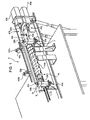
Figure 1 shows a perspective view of a modular element according to the present invention and of a first embodiment of a conveying unit incorporating such modular element; -
Figure 2 shows a section along line II-II ofFigure 1 ; -
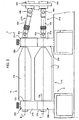
Figure 3 shows a lateral view of the first embodiment of a conveying unit incorporating the modular elements ofFigure 1 ; -
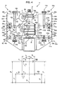
Figure 4 shows a frontal view of the first embodiment of the conveying unit ofFigure 1 ; -
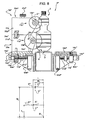
Figures 5 and6 show respective frontal views of a second embodiment of the conveying unit incorporating the modular element ofFigure 1 while processing containers having respective format different from one another; -
Figure 7 shows a frontal view of the second embodiment of the conveying unit, with parts sectioned; -
Figure 8 shows a frontal view of a third embodiment of the conveying unit incorporating the modular element ofFigure 1 ; -
Figure 9 shows a lateral view of a fourth embodiment of a conveying unit incorporating the modular element ofFigure 1 ; -
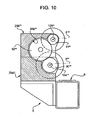
Figure 10 shows a section along line X-X ofFigure 9 ; -
Figure 11 shows a lateral view of a fifth embodiment of a conveying unit incorporating the modular element ofFigure 1 ; and -
Figure 12 is a section along line XII-XII ofFigure 11 ; and -
Figure 13 shows a schematic top view of a container processing machine incorporating the modular element ofFigure 1 . -
Number 1a in the accompanying Figures indicate as a whole a modular element for a machine 2 (Figure 13 ) forprocessing containers 3, such as bottles, pots, cans and the like. - Non-limitative examples of such products include not only food products such as milk, fruit juices or beverages in general, although also mineral lubricating or detergent oils are sold in containers having different shapes and size.
-
Machine 2 may be a rinsing machine for rinsing the containers, a filling machine for filling the containers with a predetermined volume of a liquid product, a capping machine for applying a plurality of caps on respective containers or a labelling machine for applying a plurality of labels on respective containers. - In the case shown,
machine 2 is a labelling machine. -
Modular element 1a is incorporated in aconveying unit 4, which substantially comprises: - a
fixed structure 5; - a
linear conveyor 6 for conveying the containers to be labelled bymachine 2 along a direction A; and - a plurality of star wheels 7 (only one of which is shown in
Figure 13 ) fed byconveyor 6 withcontainers 3 andfeeding containers 3 along a circumferential arc shaped trajectory. - Star
wheels 7 rotate along respective vertical axes and comprise a plurality of angularly equi-spaced seats forrespective containers 3. -
Modular element 1a advantageously comprises (Figure 4 ): - a pair of
support elements 20a; - releasable connecting means 30a for releasably connecting
such support elements 20a tofixed structure 5; and - a worm-
screw 11a which rotates about axis A relative to supportelements 20a and is adapted to cooperate with afirst portion 8a ofcontainers 3 advancing onconveyor 6 in order to distance them at a given pitch; - In particular, axis A is horizontal, axis B is horizontal and orthogonal to axis A and axis C is vertical and, therefore, orthogonal to both axes A, B.
- Axis D is fixed with respect to
structure 5, and is parallel to axis A. - In the embodiment shown, axis D coincides with the direction along which
containers 3 advance onconveyor 6. - In particular,
support elements 20a are arranged at opposite end of worm-screw 11a relative to axis A. - Each
support element 20a substantially comprises: - a parallelepiped
main portion 21a; and - a
lateral portion 22a integral with main portion 21 and defining an apex 23a, which extends towardsconveyor 6. - In particular
main portion 21a comprises atop surface 24a and abottom surface 25a. - Connecting means 30a releasably connect
support element 20a of eachmodular element 1a to aplate 19a, which is connected tostructure 5. - Connecting means 30a substantially comprise, for each
modular element 1a,: - a pair of
holes 31a defined byrelative surface 25a; - a pair of
pins 32a whose top halves engagerespective holes 31a and whose bottom halves engagerespective holes 49a ofplate 19a; - a screwed
hole 33a interposed betweenholes 31a and defined bysurface 25a; and - a screwed
pin 35a engaging hole 33a and passing throughplate 19a. - Each
modular element 1a further comprises connectingmeans 36a. - Connecting means 36a substantially comprise, for each
support element 20a,: - a pair of
holes 37a defined byrelative surface 24a; - a pair of
pins 38a whose bottom halves engagerespective holes 33a; and - a screwed
hole 39a interposed betweenholes 37a and defined bysurface 24a. -
Apices 23a ofsupport elements 20a houserespective bearings 26a, which supportbody 13a rotatably with respect to axis A (Figure 2 ). - Conveying
unit 4 comprises (Figure 4 ): -
modular element 1a; - a
modular element 1b, which is arranged over and is releasably connected withmodular element 1a; - a
modular element 60a, which is arranged on the opposite side ofmodular elements conveyor 6; and - a
modular element 60b, which is arranged overmodular element 60a and is releasably connected tomodular element 60a. -
Modular element 1b is similar tomodular element 1a and will be disclosed hereinafter only insofar as it differs from the latter; corresponding parts or equivalents ofmodular elements -
Modular element 1b differs frommodular element 1a in that: - worm-
screw 11b (not shown inFigure 1 for sake of simplicity) rotates about axis E relative to supportelement 20b and is adapted to cooperate with asecond portion 8b ofcontainers 3 advancing onconveyor 6; - worm-
screw 11b is fixed to supportelements 20b with respect to an axis F transversal to axis E and to an axis G transversal to both axes E, F; and in that -
support element 20b support axis E of worm-screw 11b at a third distance M1 from reference axis D measured parallel to axis F and at a fourth distance M2 from axis D measured parallel to axis G. - More precisely, axes E, F, G are parallel and arranged above respectively axes A, B, C.
- Third and fourth distances M1, M2 are associated to the format of
containers 3 to be conveyed. - In a completely analogous manner with respect to support
element 20a,support element 20b comprises: - a parallelepiped
main portion 21b; and - a
lateral portion 22b integral with main portion 21 and defining an apex 23b, which extends towardsconveyor 6. - In particular,
main portion 21b comprises atop surface 24b and abottom surface 25b. - Furthermore, connecting means 30b of
modular element 1b are releasably connected to connectingmeans 36a ofmodular element 1a. - More precisely, connecting means 30b substantially comprise, for each
support element 20b, (Figure 4 ): - a pair of
holes 31b defined byrelative surface 25b and engaged by top halves ofrespective pins 38a; - a through
hole 33b; and - a screwed hollow-
pin 45b passing throughhole 33b and screwed withinhole 39a. - Each
modular element Figure 1 ): - a pair of
support elements - a
fixed guide portions 9b containers 3 advancing onconveyor 6. - More precisely,
portion 9b is arranged in front ofportion 8b and overportions -
Support element relative guides 6a, 66b at a relative distance N1, O1 from reference axis D measured parallel to axis B, F and at a relative distance N2, 02 from axis D measured parallel to axis C, G. More precisely, N1, O1 and N2, O2 represent the distance between axis D and homologous points ofguides - At least one between distances N1, N2 is associated to the format of said
containers 3 to be conveyed. - In a completely analogous manner, at least one between distances O1, O2 is associated to the format of said
containers 3 to be conveyed. - In particular, each
pair support elements relative guide - Each
support element - a parallelepiped
main portion - a
lateral arm main portion conveyor 6 andrespective apex main portion relative guide - In particular,
main portion support element top surface bottom surface 85a, 85b. -
Modular element 60a comprises: - connecting means 71a for releasably connecting each
support element 65a to aplate 19b of fixedstructure 5; and - connecting means 72a for releasably connecting each
support element 65a to supportelement 65b ofmodular element 60b. - Furthermore,
modular element 60b comprises connecting means 71b for releasably connecting eachsupport element 65b to connectingmeans 72a ofrelative support element 65a ofmodular element 60a. - In particular, connecting
means 71a comprise, for eachsupport element 65a,: - a pair of
holes 100a defined bysurface 85a; - a pair of
pins 101a whose top halves engagerespective holes 100a and whose bottom halves engage respective holes 32b ofplate 19b; - a screwed
hole 102a interposed betweenholes 100a and defined bysurface 85a; and - a screwed
pin 104a passing through ahole 35b defined byplate 19b and screwed withinhole 102a. - In particular,
hole 35b is interposed between holes 32b. - Connecting means 72a comprise, for each
support element 65a,: - a pair of
holes 110a defined bysurface 84a; - a pair of
pins 111a whose bottom halves engagerespective holes 110a; and - a screwed
hole 112a interposed betweenholes 110a and defined bysurface 84a. - Connecting means 71b substantially comprise, for each
support element 65b,: - a pair of
holes 101b defined by relative surface 85b and engaged by top halves ofrespective pins 111a ofrelative support element 65a; - a through
hole 102b; and - a screwed
hollow pin 105b passing throughhole 102b and screwed withinhole 112a. - Conveying
unit 4 further comprises a pair ofmotors joints Figures 1 and3 ). - Each joint 41a, 41b comprises a
first shaft respective motors shaft screws - More precisely,
shaft cardan joints modular elements modular elements -
Joints - In use,
conveyor 6 advancescontainers 3 parallel to axis A towardsstar wheel 7. - Upstream from worm-
screws unit 4,containers 3 come in mutual contact one with respect to another. - Worm-
screws portions containers 3 and sequencesuch containers 3 at a given pitch, which corresponds to the angular distance between the seats ofstar wheel 7. - As
first portions 8a ofcontainers 3 cooperate with worm-screw 11a ofmodular element 1a,second portion 8b of worm-screw 11 ofmodular element 1b,third portions 9a ofcontainers 3 cooperate withguide 66a andfourth portions 66b ofcontainers 3 cooperate withguide 66b. -
Motors joints screws -
Apices modular element screw - More precisely, distances L1, L2 and M1, M2 are such that worm-
screw portions 8b containers 3, so efficiently conveyingsuch containers 3 and distancing them at the given pitch. -
Modular elements - In case that the format of
containers 3 changes, i.e. because diameter or height ofcontainers 3 changes,modular element 1b is removed frommodular element 1a andmodular element 1a is removed form fixedstructure 5. In a completely analogous manner,modular element 60b is removed frommodular element 60a andmodular element 60a is removed fromplate 19b fixedstructure 5. - In particular,
shafts screws shafts joints - New
modular elements new containers 3 to convey. - In other words, new
modular elements containers 3 are efficiently conveyed. - For example, in case that the diameter of
new containers 3 is smaller than the diameter ofcontainers 3 previously conveyed, axes A, E of worm-screws modular element modular element - Accordingly, new distances L1, L2, M1, M2, N1, N2, O1, O2 associated to new
modular element modular element -
Shafts joints shafts screws modular element - In this way, even if axis A of worm-
screw modular element 1 is staggered with respect to axis A, E of relative worm-screw modular element same motors - With reference to
figure 5 to 7 , 4' indicates a second embodiment of conveying unit. - Conveying unit 4' is similar to conveying
unit 4 and will be disclosed hereinafter only insofar as it differs from the latter; corresponding parts or equivalents of conveyingunits 4, 4' will be indicated, where possible, by the same reference numerals. - Conveying unit 4' differs from conveying
unit 4 in that it comprises furthermodular elements 1a', 1b' instead respectively ofmodular elements - Accordingly, conveying unit 4' comprises further worm-
screws 11a', 11b' rotatably supported bysupport elements 20a', 20b' rotatably about respectively axes A' E'. - Worm-
screw 11b' ofmodular element 1b' is arranged above worm-screw 11a' ofmodular element 1a', and axis E' is arranged above and parallel to axis A'. -
Support elements 20a' support axis A' of worm-screw 11a' at a distance N1' from axis D measured parallel to axis F' and at a distance N2' measured parallel to axis G'. At least one between distances N1', N2' is chosen on the basis of the format ofcontainers 3 to be conveyed. - In a completely analogous manner,
support elements 20b' support axis E' of worm-screw 11b' at a distance O1' from axis D measured parallel to axis F' and at a distance O2' measured parallel to axis G'. At least one between distances O1'; O2' is chosen on the basis of the format ofcontainers 3 to be conveyed. - Connecting means 30a' releasbaly connect each
support element 20a' ofmodular element 1a' toplate 19b of fixedstructure 5. - Connecting means 30b' are releasably connected with connecting
means 36a' ofsupport element 20a' ofmodular element 1a'. In this way, eachsupport element 20b' ofmodular element 1b' is releasably connected to acorresponding support element 20a' ofmodular element 1a'. - Finally, conveying unit 4' differs from conveying
unit 4 in that it comprises: - a pair of further motors (not shown); and
- a pair of further joints (not shown).
- Each further joint comprises a further shaft (not shown) which is articulated onto an output shaft of respective motor (not shown) through a first cardan joint and which is articulated onto
shaft 12a' , 12b' of respective worm-screws through a second cardan joint. - Each further shaft comprises two rods telescopically coupled with one another.
- In a completely analogous manner to
joints - The operation of conveying unit 4' differs from the operation of conveying
unit 4 in that not only first andsecond portions containers 3 cooperate respectively with worm-screw modular elements fourth portions such containers 3 cooperate respectively with worm-screw 11a', 11b' ofmodular elements 1a', 1b'. - Furthermore,
shafts 12a', 12b' of worm-screws 11a', 11b' are driven in rotation by further motors through further joint. - In case that the format of
containers 3 changes, i.e. because diameter or height ofcontainers 3 changes,modular element 1b' is removed frommodular element 1a', andmodular element 1a' is removed form fixedstructure 5. - In particular,
shafts 12a', 12b' of worm-screw 11a', 11b' are disconnected by further second shafts of relative further joints. - New
modular elements new containers 3 to be conveyed. - In other words, new
modular elements containers 3 are efficiently conveyed and distanced at the given pitch. - With reference to
figure 8 ,4 " indicates a third embodiment of conveying unit. - Conveying
unit 4" is similar to conveying unit 4' and will be disclosed hereinafter only insofar as it differs from the latter; corresponding parts or equivalents of conveyingunits 4', 4" will be indicated, where possible, by the same reference numerals. - Conveying
unit 4" differs from conveying unit 4' for not comprisingmodular elements 1a', 1b'. - Furthermore,
plates 19a", 19b" and, therefore,modular elements 1a", 1b" of conveyingunit 4" may slide along axis B" relative respectively toplates 18a", 18b" of fixedstructure 5. - In this way, it is possible to adjust position of
modular elements 1a", 1b" relative tocontainers 3. - More precisely, each
plate 19a", 19b" comprises, on the opposite side of worm-screws: -
respective protrusions 17a", 17b" housed with gap into respective grooves 16a", 16b" ofplates 18a", 18b", and comprising, in turn, respective through holes, which are screwed parallel to axis B" and are engaged byscrew 67a", 67b" extending parallel to axis B; and - respective pair of screwed through holes 68a", 68b" which are coupled with
respective screws 69a", 69b". - More precisely, screwed holes and screws 69a", 69" extend parallel to axis C".
- The operation of conveying
unit 4" is similar to the operation of conveying unit 4' and is therefore not hereinafter described. - With reference to
figures. 9 and10 , 4'" indicates a fourth embodiment of conveying unit. - Conveying unit 4'" differs from conveying unit 4' for comprising neither
motor 40b nor joint 41b. - Furthermore, conveying unit 4'" differs from conveying unit 4' for comprising:
- a gear 90'" driven in rotation by joint 41a'" and angularly integral with
shaft 12a'" of worm-screw 11a'"; - a gear 91'" angularly integral with
shaft 12b'" of worm-screw 11b"'; and - an
idler gear 92"' meshing with both gears 90'" and 91"'. - In particular,
shafts 12a"', 12b'" of worm-screws 11a"', 11b"', are coaxial withrespective gears 90"', 91"'. - Finally, conveying
unit 4"' differs from conveying unit 4' in that eachmodular elements 1a"', 1b"' comprises: - a pair of
support element 20a"', 20b'" arranged at the end of worm-screws 11a"', 11b"' facing motor 40"'; and - a
block 29a"', 29b'" axially interposed betweensupport elements 20a"', 20b'" arranged at the end of worm-screws 11a"', 11b'" facing motor 40". -
Blocks 29a'" define together withblock 29b'" define relative cavities 93'" housing gears 90"', 91''', 92'''. - The operation of conveying unit 4''' differs from the operation of conveying unit 4' in that both worm-
screws 11a"', 11b"' are driven in rotation bysame motor 40a"'. - More precisely,
motor 40a'" drives joint 41a"', which drives inrotation gear 90"'. Gear 90'" drives in rotation bothshaft 12a'" of worm-screw 11a"' and gear 91"'. Gear 91'" drives in rotation gear 92'" which, in turn, drives inrotation shaft 12b'" of worm-screw 11b"'. - With reference to
figures 11 and12 , 4"" indicates a fourth embodiment of conveying unit. - Conveying
unit 4"" is similar to conveying unit 4' and will be disclosed hereinafter only insofar as it differs from the latter; corresponding parts or equivalents of conveyingunits 4"", 4' will be indicated, where possible, by the same reference numerals. - Conveying
unit 4"" differs from conveying unit 4' for comprising only onemotor 40a"" for driving in rotation both worm-screw 11a"" ofmodular element 1a"" and worm-screw 11b'" ofmodular element 1b"". - Furthermore, conveying
unit 4"" differs from conveyingunit 4" for comprising: - a
pulley 75"" driven in rotation by output shafts ofmotor 40a"" and driving in rotation ashaft 50a"'; - a
pulley 76"" connected to ashaft 50b""; and - a belt 77"" wound on
pulleys 75"", 76"". - More precisely,
shafts 42a"", 42b"" of joint 41a"", 41b"" are articulated via cardan joint 46a"" , 46b"" respectively ontoshafts 50a"", 50b"". -
Pulleys 75"", 76"" and belt 77"" are housed within ahousing 78"". - The operation of conveying
unit 4"" differs from conveying unit 4' in thatmotor 40a"" drives inrotation pulley 75"". -
Pulley 75"" drives bothshaft 42a"' of joint 41a'''' and belt 77'''', which in turn, drives pulley 76''''. - Joint 41a'''' drives in rotation worm-
screw 11b'''' about axis E'''' whilepulley 76.'''' drivesshaft 42b''' of joint 41b''''. - Joint 41b''' drives, in turn, in rotation worm-
screw 11b''''. - From an analysis of the features of
modular element modular element 60a, 6.0b made according to the present invention, the advantages it allows to obtain are apparent. - In particular,
modular element screw containers 3 to be conveyed. - Accordingly, it is sufficient to replace
modular elements 1a (1b) with newmodular elements 1a (1b) arranging axis A (E) of worm-screw 11a (11b) at different distances L1, L2, M1, M2, N1', N2', O1, O2' from axis D in order to reconfigure conveyingunit 4, 4' , 4'', 4''', 4'''' for a new format ofcontainers 3. - In this way,
modular element containers 3 at an ideal position relative to worm-screw - In a completely analogous way,
modular element 60a (60b) allows to arrangeguide 66a (66b) at designed distances N1 and N2 (O1 and O2) from axis D measured parallel to axis B and C (F and G), on the basis of the format ofcontainers 3 to be conveyed. - Resulting conveying
unit 4, 4', 4'', 4''', 4'''' is therefore highly modular and can be reconfigured without requiring highly skilled personnel for processingcontainers 3 of different format. - As the risk that operator errors result could result in a damage of
containers 3 is highly reduced, conveyingunit 4, 4', 4'', 4''',, 4'''' are particularly advantageous for conveying evencontainers 3 with delicate surface at very high speeds. - Furthermore,
modular element unit 4, 4' 4'' 4''', 4''''. - Conveying unit 4''', 4'''' requires only one
motor 40a''', 40a'''' for driving in rotation both worm-screws 12a''', 11b''' and 11a'''', 11b''''. - Accordingly, conveying unit 4''', 4'''' does not require additional spaces and infra-structure for housing a further motor.
- In this way, conveying unit 4'''' may be reconfigured without requiring additional spaces for housing a plurality of
motors 40a''''. - Even, conveying unit 4''' requires only one joint 41a''' for driving in rotation both worm-
screws 11a''', 11b'''. - Accordingly, conveying unit 4''' conveys
containers 3 in a particularly economic way. - Finally, it is apparent that modifications and variants not departing from the scope of protection of the claims may be made to
modular element - In particular, conveying
unit 4, 4' , 4'', 4''', 4'''' could comprise only onemodular element 1a (1b), 1a' (1b'), 1a'' (1b''), 1a''' (1b''') , 1a'''' (1b''''). - Conveying
unit 4 could comprise only onemodular element - Conveying
unit 4, 4', 4'' could comprise only onemotor 40a for driving in rotation both worm-screws - In this case,
motor 40a could be connected to worm-screws - only one joint 41a''' and gears 90''', 91''', 92'''; or
- two
joints 41a'''', 41b'''' driven respectively by pulleys 75'''', 76'''' and belt 77''''. - Conveying unit 4''', 4'''' could comprise one or more
modular element modular elements 1a', 1b'. - Conveying
unit 4, 4'', 4''', 4'''' could compriseprotrusion 17a", 17b'', grooves 16a'', 16b'', screws 67a'' , 69a" and holes 68a''. - Finally, conveying
unit 4, 4'', 4''', 4'''' could comprise other coupling means for renderingrespective plates plates
first and second distances L1, L2 are associated to the format of
Claims (15)
- Modular replaceable element (1a, 1b; 1a', 1b' ; 1a'', 1b''; 1a''', 1b'''; 1a'''', 1b'''') for a container processing machine (2), characterized by comprising:- at least one first support element (20a, 20b; 20a', 20b'; 20a''', 20b''');- first releasable connecting means (30a, 30a') for releasably connecting said first support element (20a, 20b; 20a', 20b'; 20a''', 20b''') to either a fixed structure (5) of said container processing machine (2) or to a further support element (20b, 20a; 20b', 20a' ; 20b''', 20a''') of a further modular element (1b, 1a; 1b', 1a' ; 1b'', 1a''; 1b''', 1a'''; 1b'''', 1a'''') ; and- at least one first worm-screw (11a, 11b; 11a', 11b' ; 11a''', 11b''' ; 11a'''' , 11b'''') which may rotate about a first axis (A, E; A', E' ; A'''', E'''') with respect to said first support element (20a, 20b; 20a', 20b' ; 20a''', 20b'''), and is adapted to cooperate with a first portion (8a, 8b) of at least two containers (3) advancing on a conveyor (6) in order to distance them at a given pitch;said first worm-screw (11a, 11b; 11a', 11b'; 11a''' , 11b'''; 11a'''', 11b'''') being fixed relative to said first support element (20a, 20b; 20a', 20b'; 20a''', 20b''') with respect to a second axis (B, F; B' , F') transversal to said first axis (A, E; A', E' ; A'''', E'''') and with respect to a third axis (C, G; C', G') transversal to said first axis (A, E; A', E'; A'''', E'''') and said second axis (B, F; B' , F') ;
said at least one first support element (20a, 20b; 20a', 20b'; 20a''', 20b''') supporting said first axis (A, E; A', E'; A'''', E'''') of said first worm-screw (11a, 11b; 11a' , 11b' ; 11a''' , 11b'''; 11a''', 11b'''') at a first distance (L1, M1, N1', O1') from a fourth fixed reference axis (D) measured parallel to said second axis (B, F; B', F') and at a second distance (L2, M2, N2', O2') from said fourth axis (D) measured parallel to said third axis (C, G; G', G');
at least one between said first and second distances (L1, L2; M1, M2; N1', N2'; O1', O2') being associated to the format of said containers (3) to be conveyed. - The modular replaceable element according to claim 1, characterized by comprising a pair of said first support elements (20a, 20b; 20a', 20b'; 20a''', 20b''') arranged on respective opposite axial sides with respect to said first axis (A, E; A', E'; A'''', E'''') of said first worm screw (11a, 11b; 11a', 11b'; 1a''', 1b''' ; 11a'''', 11b'''').
- The modular replaceable element according to claim 1 or 2, characterized in that said first support element (20a, 20b; 20a', 20b'; 20a''', 20b''') comprises:- a first main portion (21a, 21b) carrying said first releasable connecting means (30a, 30b); and- a first end portion (22a, 22b) connected to said first main portion (21a, 21b) and defining an apex (23a, 23b) which protrudes, in use, towards said further conveyor (6); said first worm-screw (11a, 11b; 11a', 11b' ; 11a''', 11b'''; 11a'''', 11b'''') being rotatably fitted to said apex (23a, 23b) about said first axis (A, E; A', E' ; A'''' , E'''').
- A conveying unit (4), comprising:- a first motor (40a, 40b, 40a''', 40a'''') ; and- at least one first replaceable modular element (1a, 1b; 1a', 1b'; 1a'''' , 1b'''; 1'''', 1'''') according to anyone of previous claims;- a first motion transmission element (41a, 41a''', 41a''''; 41b) functionally interposed between said first worm-screw (11a, 11b; 11a', 11b'; 11a''', 11b'''; 11a'''', 11b'''') of said modular element (1a, 1b; la', 1b' ; 1a''', 1b'''; 1a'''', 1b'''') and said first motor (40a, 40b, 40a'''', 40a'''') ;
said transmission element (41a, 41b, 41a''', 41a'''') being capable of transmitting the motion between two directions parallel or coincident to one another. - The conveying unit according to claim 4, characterized in that said transmission element (41a, 41a''', 41a''''; 41b) is a first joint (41a, 41a''', 41a''''; 41b) which comprises a first shaft (42a, 42a'''', 42a'''', 42b) ;
said first shaft (42a, 42a''' , 42a'''', 42b) being connected with a first output shaft of said first motor (40a, 40b, 40a''', 40a'''') through a first cardan joint (46a, 46a''', 46a'''', 46b) and being connected with said first worm-screw (11a, 11b; 11a', 11b'; 11a'''', 11b'''; 11a'''', 11b'''') through a second cardan joint (43a, 43a''', 43a'''', 43b). - The conveying unit according to claim 4 or 5, characterized by comprising:- a second modular replaceable element (1b, 1a; 1b', 1a'; 1b'', 1a''; 1b''', 1a'''; 1b'''', 1a'''') comprising, in turn, at least one second support element (20b, 20a; 20b', 20a'; 20b'', 20a''; 20b''', 20a'''; 20b'''', 20a'''') and a second worm-screw (11b, 11a; 11b', 11a'; 11b'', 11a''; 11b''', 11a'''; 11b'''', 11a'''') which may rotate about a fifth axis (E, A; E', A' ; E'''' ; A'''') with respect to said second support element (20b, 20a; 20b', 20a'; 20b'', 20a''; 20b''', 20a''');
said second worm-screw (11b, 11a; 11b', 11a'; 11b'', 11a''; 11b''', 11a'''; 11b'''', 11a'''') being adapted to cooperate with a second portion (8b, 8a) of at least said two containers (3);
said second worm-screw (11b, 11a; 11b', 11a'; 11b'', 11a''; 11b''', 11a'''; 11b'''', 11a'''') being fixed relative to said at least one second support element (20b, 20a; 20b', 20a'; 20b'', 20a''; 20b''', 20a''') with respect to a sixth axis (F; B) transversal to said fifth axis (E, A; E', A'; E''''; A'''') and with respect to a seventh axis (G, C; G', C') transversal to said fifth and sixth axis (F, B; F', B');
said first and second support element (20b, 20a ; 20b', 20a'; 20b'', 20a''; 20b''', 20a''') respectively comprising second and third releasable connecting means (36b, 36b'; 30a, 30a') releasably connected to one another;
said second support element (20b, 20b'; 20a, 20a') supporting said fifth axis (E, A; E', A'; E''''; A'''') of said second worm-screw (11b, 11a; 11b, 11a'; 11b'', 11a'' ; 11b''', 11a'''; 11b'''', 11a'''') at a third distance (M1; L1; O1' ; N1') from said fourth axis (D) measured parallel to said second axis (B; F) and at a fourth distance (M2; L2; O2'; N2') from said fourth axis (D) measured parallel to said third axis (C; G);
at least one between said third and fourth distances (M1, M2; L1, L2; O1'; O2'. N1'; N2') being associated to the format of said containers (3) to be conveyed. - The conveying unit according to claim 6, characterized in that:- said first modular replaceable element (1a, 1b; 1a', 1b' ; 1a'', 1b''; 1a''', 1b'''; 1a'''', 1b'''') comprises a first shaft (12a, 12b; 12a', 12b'; 12a''', 12b''' ; 12a'''', 12b''''), which is rotatably supported by said first support element (20a, 20b; 20a', 20b'; 20a'', 20b''; 20a''', 20b''') about said first axis (A, E; A', E'; A''', E'''') and is integrally rotatable together with said first worm-screw (11a, 11a'; 11b, 11b') about said first axis (A, E; A', E'; A'''', E'''') ;- said second modular replaceable element (1b, 1a; 1b', 1a'; 1b'', 1a''; 1b''', 1a'''; 1b'''', 1a'''') comprises a second shaft (12b, 12a; 12b', 12a'; 12b''', 12a''' ; 12b'''', 12a''''), which is rotatably supported by said second support element (20b, 20b'; 20a, 20a') about said fifth axis (E, A; E', A' ; E'''', A'''') and integrally rotatable together with said second worm-screw (11b, 11a; 11b', 11a' ; 11b'', 11a''; 11b''', 11a''' ; 11b'''', 11a'''') about said fifth axis (E, A; E', A' ; E'''', A'''').
- The conveying unit according to claim 7, characterized by comprising:- a first gear (90''') rotatable integrally with said first shaft (12a''') and driven in rotation, in use, by said first motor (40a'''); and- a second gear (91''') rotatable integrally with said second shaft (12b'''); and- a third gear (92''') meshing with said first and second gears (90''', 91''') ;
and/or characterized by comprising a second joint (41b, 41b'''') connected to said second worm-screw (11b, 11a; 11b', 11a'; 11b'' , 11a'' ; 11b''', 11a'''; 11b'''', 11a'''' ). - The conveying unit according to claim 8, characterized by comprising:- a first pulley (75'''') operatively connected to said first motor (40a'''') and said first joint (41a'''') ;- a second pulley (76'''') operatively connected to said second joint (41b'''') ; and- a belt (77'''') wound onto said first and second pulleys (75'''', 76'''').
- The conveying unit according to anyone of claims 4 to 9, characterized by comprising:- a third modular replaceable element (60a, 60b);
said third modular element (60a, 60b) comprising, in turn,:- at least one third support element (65a, 65b);- fourth releasable connecting means (71a, 71b) for releasably connecting said third support element (65a, 65b) either to said fixed structure (5) or to a fourth support element (65b, 65a);- at least one fixed guide (66a, 66b) adapted to cooperate with a third portion (9a, 9b) of said containers (3) advanced by said conveyor (6);
said guide (66a, 66b) being arranged at a fifth distance (N1, O1) from said fourth axis (D) measured parallel to said second axis (B), and a at a sixth distance (N2, O2) from said fourth axis (D) measured parallel to said third axis (C);
at least one between said fifth and sixth distance (N1, O1; N2, O2) being associated to the format of said containers (3) to be conveyed;
and/or characterized in that said first support element (20a, 20b; 20a', 20b'; 20a''', 20b''') may slide relative to said fixed structure (5). - A container processing machine, comprising:- at least one star wheel (7); and- a conveying unit (4, 4', 4'', 4''', 4'''') according to any one of claims 4 to 10 and arranged upstream from said star wheel (7).
- A series of conveying units (4, 4', 4'', 4''', 4'''') for a container processing machine (2), characterized in that each conveying unit (4, 4', 4'', 4''', 4"") comprises a modular replaceable element (1a, 1b; 1a', 1b'; 1a'', 1b''; 1a''', 1b'''; 1a'''', 1b'''');
said modular replaceable element (1a, 1b; 1a', 1b'; 1a'', 1b''; 1a"', 1b'''; 1a'''', 1b'''') comprising:- at least one first support element (20a, 20b; 20a' , 20b' ; 20a''', 20b''');- first releasable connecting means (30a; 30a') for releasably connecting said first support element (20a, 20b; 20a', 20b'; 20a"', 20b"') either to a fixed structure (5) of said container processing machine (2) or to a second support element (20b, 20a; 20b', 20a'; 20b''', 20a''');- at least one first worm-screw (11a, 11b; 11a', 11b'; 11a''', 11b'''; 11a'''', 11b'''') which may rotate about a first axis (A, E; A', E'; A'''', E''") with respect to said first support element (20a, 20a'; 21b, 21b'), and is adapted with cooperate with a first portion (8a, 8b) of at least two containers (3) advancing on a conveyor (6) along a second axis (D) parallel to said first axis (A, E; A', E'; A'''', E'''') in order to distance them at a given pitch;said first worm-screw (11a, 11b; 11a', 11b'; 11a"', 11b"'; 11a"", 11b"") being fixed relative to said first support element (20a, 20b; 20a', 20b'; 20a"', 20b''') with respect to a third axis (B, F; B' , F') transversal to said first axis (A, E; A', E'; A'''', E'''') and with respect to a fourth axis (C, G; C', G') transversal to said first axis (A, E; A', E'; A'''', E'''') and said third axis (B, F; B', F') ;
said at least one first support element (20a, 20a'; 20b, 20b') supporting said first axis (A, E; A', E'; A'''', E"") of relative said first worm-screw (11a, 11b; 11a' , 11b'; 11a''', 11b'''; 11a'''', 11b'''') at a relative first distance (L1, M1, N1', O1') from said second axis (D) measured parallel to said relative third axis (B, F; B', F') and at a relative second distance (L2, M2, N2", O2') from said fourth axis (D) measured parallel to said third axis (C, G; C', G');
at least one between said first and second distances (L1, L2; M1, M2; N1', N2'; O1', O2') being associated to the format of relative said containers (3) to be conveyed. - A series of conveying units (4, 4' , 4'', 4''', 4'''') according to claim 12, characterized in that each conveying unit (4, 4', 4'', 4''', 4'''') comprises a second modular replaceable elements (1b, 1a; 1b', 1a'; 1b'', 1a''; 1b''', 1a'''; 1b'''', 1a'''');
said second modular replaceable element (1b, 1a; 1b', 1a'; 1b'' , 1a" ; 1b''', 1a"'; 1b'''', 1a"") comprising, in turn,:- a second support element (20b, 20b'; 20a, 20a'); and- a second worm-screw (11b, 11a; 11b', 11a'; 11b'', 1a''; 11b''', 11a'''; 11b'''', 11a'''') which may rotate about a fifth axis (E, A; E', A'; E'"'; A'''') with respect to said second support element (20b, 20b'; 20a, 20a');
said second worm-screw (11b, 11a; 11b', 11a'; 11b" , 11a''; 11b''', 11a'''; 11b'''', 11a'''') being fixed relative to said at least one said second support element (20b, 20b'; 20a, 20a') with respect to a sixth axis (F; B) transversal to said fifth axis (E, A; E', A'; E''''; A'''') and with respect to a seventh axis (G; C) transversal to said sixth axis (F; B) and said fifth axis (E, A; E', A'; E''''; A'''');
said at least one first and second support element (20a, 20a'; 20b, 20b') respectively comprising second and third releasable connecting means (36b, 36b'; 30a, 30a') releasably connected to one another;
said fifth axis (E, A; E', A'; E''''; A'''') being arranged at a third distance (M1, L1; O1', N1') from said fourth axis (D) and at a fourth distance (M2, L2 O2, N2) from said fourth axis (D);
at least one between said third and fourth distance (M1, M2; L1, L2) being associated to the format of the containers (3) to be conveyed. - A series of conveying units according to claim 12 or 13, characterized in that each conveying unit (4) comprises a third modular replaceable element (60a, 60b) comprising, in turn,:- at least one fixed guide (66a, 66b) adapted to cooperate with a third portion (9a, 9b) of said containers (3) advancing parallel to said first axis (A, E; A', E'; A'''', E''''); and- at least one third support element (60a, 60b) which comprises fourth releasable connecting means (71a; 71b) for releasably connecting said third support element (60a; 60b) to either said fixed structure (5) or to a fourth support element (60b; 60a);
said guide (66a; 66b) being arranged at a fifth distance (N1; O1) from said fourth axis (D) measured parallel to said second axis (B), and at a sixth distance (N2; O2) from said fourth axis (D) measured parallel to said third axis (C);
at least between said fifth and said sixth distance (N1, N2; O1, O2) being associated to the format of said containers (3) to be conveyed. - Method for adapting a conveying unit (4, 4', 4'', 4''', 4''') for a container processing machine (2) to a different format of containers (3), said conveying unit (4, 4', 4'', 4''', 4''') comprising:- a modular replaceable element (1a, 1b; 1a', 1b', 1a", 1b'', 1a''', 1b''', 1a'''', 1b'''')- a fixed structure (5);- at least one first worm-screw (11a, 11b; 11a', 11b'; 11a''', 11b'''; 11a'''', 11b'''') which may rotate relative to said fixed structure (5) about a first axis (A, E; A', E'; A"'', E''");
said first worm-screw (11a, 11b; 11a', 11b'; 11a"', 11b'''; 11a'''', 11b'''') being adapted to cooperate with a first portion (8a, 8b) of said containers (3) advancing parallel to said first axis (A, E; A' , E'; A'''', E'''') in order to distance them at a given pitch, said method being characterized by comprising the steps of:choosing a new modular element support element (1a, 1b; 1a', 1b'; 1a'', 1b''; 1a''', 1b'''; 1a'''', 1b'''') to replace modular rotatably supporting said first worm-screw (11a, 11b; 11a', 11b'; 11a''', 11b'''; 11a'''', 11b'''') about said first axis (A, E; A', E' ; A"", E''") on the basis of at least one between a first distance (L1; M1) between said first axis (A, E; A', E' ; A'''', E'''') and a fixed second reference axis (D) measured parallel to a third axis (B, B') transversal to said first axis (A, E; A', E'; A'''', E''''), and a second distance (L2; M2) between said first axis (A, E; A' , E' ; A'''', E'''') and said second reference axis (D) measured parallel to a fourth axis (C, C') transversal to both said first and second axes (A, B); and- releasably connecting said new modular support element (1a, 1b; 1a', 1b'; 1a'', 1b'' ; 1a''', 1b'''; 1a'''', 1b"") to said fixed structure (5).
Applications Claiming Priority (1)
| Application Number | Priority Date | Filing Date | Title |
|---|---|---|---|
| PCT/IT2010/000025 WO2011092723A1 (en) | 2010-01-29 | 2010-01-29 | Modular element for a container processing machine |
Publications (2)
| Publication Number | Publication Date |
|---|---|
| EP2528847A1 EP2528847A1 (en) | 2012-12-05 |
| EP2528847B1 true EP2528847B1 (en) | 2014-06-18 |
Family
ID=42938442
Family Applications (1)
| Application Number | Title | Priority Date | Filing Date |
|---|---|---|---|
| EP10707136.7A Not-in-force EP2528847B1 (en) | 2010-01-29 | 2010-01-29 | Modular element for a container processing machine |
Country Status (2)
| Country | Link |
|---|---|
| EP (1) | EP2528847B1 (en) |
| WO (1) | WO2011092723A1 (en) |
Cited By (1)
| Publication number | Priority date | Publication date | Assignee | Title |
|---|---|---|---|---|
| AU2019208232B2 (en) * | 2018-08-01 | 2025-08-07 | Mbf S.P.A | Screw transport apparatus for bottles and bottling system provided with such an apparatus |
Families Citing this family (6)
| Publication number | Priority date | Publication date | Assignee | Title |
|---|---|---|---|---|
| CN103708395B (en) * | 2014-01-08 | 2016-05-18 | 广州达意隆包装机械股份有限公司 | A kind of bottle of device that type is changed and located fast |
| JP6595846B2 (en) * | 2015-08-26 | 2019-10-23 | 株式会社前川製作所 | Sorting device |
| JP6595845B2 (en) * | 2015-08-26 | 2019-10-23 | 株式会社前川製作所 | Transport device |
| DE102015120426A1 (en) * | 2015-11-25 | 2017-06-01 | Esomatec Gmbh | Device and method for separating and / or testing containers |
| CN108928788B (en) * | 2017-05-25 | 2023-12-29 | 广州隆宝科技技术有限公司 | Bottle-shaped part quick-change structure and filling equipment |
| DE102018109770A1 (en) * | 2018-04-24 | 2019-10-24 | Khs Gmbh | Device for the production of containers |
Family Cites Families (3)
| Publication number | Priority date | Publication date | Assignee | Title |
|---|---|---|---|---|
| JPS58162423A (en) * | 1982-03-19 | 1983-09-27 | Mitsubishi Electric Corp | Article feeding and discharging apparatus |
| DE8714646U1 (en) * | 1987-11-04 | 1988-12-15 | Kronseder, Hermann, 93086 Wörth | Device for dividing containers transported in a single lane on a conveyor |
| US4947979A (en) * | 1988-09-14 | 1990-08-14 | R & B Machine Tool Company | Transfer apparatus |
-
2010
- 2010-01-29 EP EP10707136.7A patent/EP2528847B1/en not_active Not-in-force
- 2010-01-29 WO PCT/IT2010/000025 patent/WO2011092723A1/en not_active Ceased
Cited By (1)
| Publication number | Priority date | Publication date | Assignee | Title |
|---|---|---|---|---|
| AU2019208232B2 (en) * | 2018-08-01 | 2025-08-07 | Mbf S.P.A | Screw transport apparatus for bottles and bottling system provided with such an apparatus |
Also Published As
| Publication number | Publication date |
|---|---|
| WO2011092723A8 (en) | 2011-12-29 |
| WO2011092723A1 (en) | 2011-08-04 |
| EP2528847A1 (en) | 2012-12-05 |
Similar Documents
| Publication | Publication Date | Title |
|---|---|---|
| EP2528847A1 (en) | Modular element for a container processing machine | |
| EP3415282B1 (en) | Workpiece conveying apparatus for a pressing machine | |
| US7721876B2 (en) | Adjustable side rails for article conveying system, and conveyor and system incorporating same | |
| US8939272B2 (en) | Article orienting machine | |
| CN116133947A (en) | Application unit, method for operating an application unit and packaging machine with an application unit | |
| CN103079959B (en) | device for sealing the open end of a container | |
| EP1442984A1 (en) | Packaging machine for wrapping products in respective sheets of heat-seal wrapping material | |
| EP2781474B1 (en) | Unit for transferring and up-ending sealed packages containing a pourable food product | |
| KR101346277B1 (en) | Apparatus for transferring of conveyor guide | |
| CN1126690C (en) | Automatic machine | |
| CN101596017B (en) | Device for transporting and holding string-form articles, method for customising such device and tubular wheel set | |
| CN215044334U (en) | Conveying device | |
| EP2643249B1 (en) | Apparatus for conveying a carriage | |
| CN207844327U (en) | A kind of chain-plate type transport device in length and breadth | |
| EP3012234B1 (en) | A dispenser for gobs of molten glass for hollow-glass forming machines | |
| CN111572092B (en) | Shaping and pressing cutting machine and pressing cutting method for multilayer hard paperboard | |
| CN212528854U (en) | Multi-size corrugated carton feeding-bending forming device | |
| CN109333169A (en) | A kind of aluminosilicate fiberboard grinding cutting automatic assembly line | |
| JP4672936B2 (en) | Container following type packaging machine system | |
| CN212830926U (en) | Bottle unscrambler guider | |
| CN216784779U (en) | Intelligent multilayer conveying device | |
| CN223238133U (en) | Can guide conveying device | |
| CN221252039U (en) | Clamping conveying mechanism | |
| EP4121358A1 (en) | Device for rotating articles of a loose article group, packaging machine with such a device, and method for rotating articles of a loose article group with the aid of such a device | |
| CN218173563U (en) | Lubricating oil production conveyor |
Legal Events
| Date | Code | Title | Description |
|---|---|---|---|
| PUAI | Public reference made under article 153(3) epc to a published international application that has entered the european phase |
Free format text: ORIGINAL CODE: 0009012 |
|
| 17P | Request for examination filed |
Effective date: 20120731 |
|
| AK | Designated contracting states |
Kind code of ref document: A1 Designated state(s): AT BE BG CH CY CZ DE DK EE ES FI FR GB GR HR HU IE IS IT LI LT LU LV MC MK MT NL NO PL PT RO SE SI SK SM TR |
|
| DAX | Request for extension of the european patent (deleted) | ||
| GRAP | Despatch of communication of intention to grant a patent |
Free format text: ORIGINAL CODE: EPIDOSNIGR1 |
|
| INTG | Intention to grant announced |
Effective date: 20131115 |
|
| GRAP | Despatch of communication of intention to grant a patent |
Free format text: ORIGINAL CODE: EPIDOSNIGR1 |
|
| INTG | Intention to grant announced |
Effective date: 20140328 |
|
| GRAS | Grant fee paid |
Free format text: ORIGINAL CODE: EPIDOSNIGR3 |
|
| GRAA | (expected) grant |
Free format text: ORIGINAL CODE: 0009210 |
|
| AK | Designated contracting states |
Kind code of ref document: B1 Designated state(s): AT BE BG CH CY CZ DE DK EE ES FI FR GB GR HR HU IE IS IT LI LT LU LV MC MK MT NL NO PL PT RO SE SI SK SM TR |
|
| REG | Reference to a national code |
Ref country code: GB Ref legal event code: FG4D |
|
| REG | Reference to a national code |
Ref country code: CH Ref legal event code: EP |
|
| REG | Reference to a national code |
Ref country code: AT Ref legal event code: REF Ref document number: 673207 Country of ref document: AT Kind code of ref document: T Effective date: 20140715 |
|
| REG | Reference to a national code |
Ref country code: IE Ref legal event code: FG4D |
|
| REG | Reference to a national code |
Ref country code: DE Ref legal event code: R096 Ref document number: 602010016768 Country of ref document: DE Effective date: 20140731 |
|
| PG25 | Lapsed in a contracting state [announced via postgrant information from national office to epo] |
Ref country code: FI Free format text: LAPSE BECAUSE OF FAILURE TO SUBMIT A TRANSLATION OF THE DESCRIPTION OR TO PAY THE FEE WITHIN THE PRESCRIBED TIME-LIMIT Effective date: 20140618 Ref country code: NO Free format text: LAPSE BECAUSE OF FAILURE TO SUBMIT A TRANSLATION OF THE DESCRIPTION OR TO PAY THE FEE WITHIN THE PRESCRIBED TIME-LIMIT Effective date: 20140918 Ref country code: CY Free format text: LAPSE BECAUSE OF FAILURE TO SUBMIT A TRANSLATION OF THE DESCRIPTION OR TO PAY THE FEE WITHIN THE PRESCRIBED TIME-LIMIT Effective date: 20140618 Ref country code: LT Free format text: LAPSE BECAUSE OF FAILURE TO SUBMIT A TRANSLATION OF THE DESCRIPTION OR TO PAY THE FEE WITHIN THE PRESCRIBED TIME-LIMIT Effective date: 20140618 Ref country code: GR Free format text: LAPSE BECAUSE OF FAILURE TO SUBMIT A TRANSLATION OF THE DESCRIPTION OR TO PAY THE FEE WITHIN THE PRESCRIBED TIME-LIMIT Effective date: 20140919 |
|
| REG | Reference to a national code |
Ref country code: NL Ref legal event code: VDEP Effective date: 20140618 |
|
| REG | Reference to a national code |
Ref country code: AT Ref legal event code: MK05 Ref document number: 673207 Country of ref document: AT Kind code of ref document: T Effective date: 20140618 |
|
| REG | Reference to a national code |
Ref country code: LT Ref legal event code: MG4D |
|
| PG25 | Lapsed in a contracting state [announced via postgrant information from national office to epo] |
Ref country code: LV Free format text: LAPSE BECAUSE OF FAILURE TO SUBMIT A TRANSLATION OF THE DESCRIPTION OR TO PAY THE FEE WITHIN THE PRESCRIBED TIME-LIMIT Effective date: 20140618 Ref country code: HR Free format text: LAPSE BECAUSE OF FAILURE TO SUBMIT A TRANSLATION OF THE DESCRIPTION OR TO PAY THE FEE WITHIN THE PRESCRIBED TIME-LIMIT Effective date: 20140618 Ref country code: SE Free format text: LAPSE BECAUSE OF FAILURE TO SUBMIT A TRANSLATION OF THE DESCRIPTION OR TO PAY THE FEE WITHIN THE PRESCRIBED TIME-LIMIT Effective date: 20140618 |
|
| REG | Reference to a national code |
Ref country code: FR Ref legal event code: PLFP Year of fee payment: 6 |
|
| PG25 | Lapsed in a contracting state [announced via postgrant information from national office to epo] |
Ref country code: EE Free format text: LAPSE BECAUSE OF FAILURE TO SUBMIT A TRANSLATION OF THE DESCRIPTION OR TO PAY THE FEE WITHIN THE PRESCRIBED TIME-LIMIT Effective date: 20140618 Ref country code: SK Free format text: LAPSE BECAUSE OF FAILURE TO SUBMIT A TRANSLATION OF THE DESCRIPTION OR TO PAY THE FEE WITHIN THE PRESCRIBED TIME-LIMIT Effective date: 20140618 Ref country code: RO Free format text: LAPSE BECAUSE OF FAILURE TO SUBMIT A TRANSLATION OF THE DESCRIPTION OR TO PAY THE FEE WITHIN THE PRESCRIBED TIME-LIMIT Effective date: 20140618 Ref country code: PT Free format text: LAPSE BECAUSE OF FAILURE TO SUBMIT A TRANSLATION OF THE DESCRIPTION OR TO PAY THE FEE WITHIN THE PRESCRIBED TIME-LIMIT Effective date: 20141020 Ref country code: ES Free format text: LAPSE BECAUSE OF FAILURE TO SUBMIT A TRANSLATION OF THE DESCRIPTION OR TO PAY THE FEE WITHIN THE PRESCRIBED TIME-LIMIT Effective date: 20140618 Ref country code: CZ Free format text: LAPSE BECAUSE OF FAILURE TO SUBMIT A TRANSLATION OF THE DESCRIPTION OR TO PAY THE FEE WITHIN THE PRESCRIBED TIME-LIMIT Effective date: 20140618 |
|
| PG25 | Lapsed in a contracting state [announced via postgrant information from national office to epo] |
Ref country code: NL Free format text: LAPSE BECAUSE OF FAILURE TO SUBMIT A TRANSLATION OF THE DESCRIPTION OR TO PAY THE FEE WITHIN THE PRESCRIBED TIME-LIMIT Effective date: 20140618 Ref country code: PL Free format text: LAPSE BECAUSE OF FAILURE TO SUBMIT A TRANSLATION OF THE DESCRIPTION OR TO PAY THE FEE WITHIN THE PRESCRIBED TIME-LIMIT Effective date: 20140618 Ref country code: AT Free format text: LAPSE BECAUSE OF FAILURE TO SUBMIT A TRANSLATION OF THE DESCRIPTION OR TO PAY THE FEE WITHIN THE PRESCRIBED TIME-LIMIT Effective date: 20140618 Ref country code: IS Free format text: LAPSE BECAUSE OF FAILURE TO SUBMIT A TRANSLATION OF THE DESCRIPTION OR TO PAY THE FEE WITHIN THE PRESCRIBED TIME-LIMIT Effective date: 20141018 |
|
| REG | Reference to a national code |
Ref country code: DE Ref legal event code: R097 Ref document number: 602010016768 Country of ref document: DE |
|
| PGFP | Annual fee paid to national office [announced via postgrant information from national office to epo] |
Ref country code: IT Payment date: 20141222 Year of fee payment: 6 |
|
| PLBE | No opposition filed within time limit |
Free format text: ORIGINAL CODE: 0009261 |
|
| STAA | Information on the status of an ep patent application or granted ep patent |
Free format text: STATUS: NO OPPOSITION FILED WITHIN TIME LIMIT |
|
| PG25 | Lapsed in a contracting state [announced via postgrant information from national office to epo] |
Ref country code: DK Free format text: LAPSE BECAUSE OF FAILURE TO SUBMIT A TRANSLATION OF THE DESCRIPTION OR TO PAY THE FEE WITHIN THE PRESCRIBED TIME-LIMIT Effective date: 20140618 |
|
| PGFP | Annual fee paid to national office [announced via postgrant information from national office to epo] |
Ref country code: DE Payment date: 20141218 Year of fee payment: 6 |
|
| 26N | No opposition filed |
Effective date: 20150319 |
|
| PGFP | Annual fee paid to national office [announced via postgrant information from national office to epo] |
Ref country code: FR Payment date: 20150121 Year of fee payment: 6 |
|
| PG25 | Lapsed in a contracting state [announced via postgrant information from national office to epo] |
Ref country code: BE Free format text: LAPSE BECAUSE OF FAILURE TO SUBMIT A TRANSLATION OF THE DESCRIPTION OR TO PAY THE FEE WITHIN THE PRESCRIBED TIME-LIMIT Effective date: 20140618 |
|
| PG25 | Lapsed in a contracting state [announced via postgrant information from national office to epo] |
Ref country code: SI Free format text: LAPSE BECAUSE OF FAILURE TO SUBMIT A TRANSLATION OF THE DESCRIPTION OR TO PAY THE FEE WITHIN THE PRESCRIBED TIME-LIMIT Effective date: 20140618 |
|
| REG | Reference to a national code |
Ref country code: CH Ref legal event code: PL |
|
| PG25 | Lapsed in a contracting state [announced via postgrant information from national office to epo] |
Ref country code: LU Free format text: LAPSE BECAUSE OF FAILURE TO SUBMIT A TRANSLATION OF THE DESCRIPTION OR TO PAY THE FEE WITHIN THE PRESCRIBED TIME-LIMIT Effective date: 20150129 |
|
| GBPC | Gb: european patent ceased through non-payment of renewal fee |
Effective date: 20150129 |
|
| PG25 | Lapsed in a contracting state [announced via postgrant information from national office to epo] |
Ref country code: MC Free format text: LAPSE BECAUSE OF FAILURE TO SUBMIT A TRANSLATION OF THE DESCRIPTION OR TO PAY THE FEE WITHIN THE PRESCRIBED TIME-LIMIT Effective date: 20140618 |
|
| PG25 | Lapsed in a contracting state [announced via postgrant information from national office to epo] |
Ref country code: CH Free format text: LAPSE BECAUSE OF NON-PAYMENT OF DUE FEES Effective date: 20150131 Ref country code: LI Free format text: LAPSE BECAUSE OF NON-PAYMENT OF DUE FEES Effective date: 20150131 Ref country code: GB Free format text: LAPSE BECAUSE OF NON-PAYMENT OF DUE FEES Effective date: 20150129 |
|
| REG | Reference to a national code |
Ref country code: IE Ref legal event code: MM4A |
|
| PG25 | Lapsed in a contracting state [announced via postgrant information from national office to epo] |
Ref country code: IE Free format text: LAPSE BECAUSE OF NON-PAYMENT OF DUE FEES Effective date: 20150129 |
|
| REG | Reference to a national code |
Ref country code: DE Ref legal event code: R119 Ref document number: 602010016768 Country of ref document: DE |
|
| REG | Reference to a national code |
Ref country code: FR Ref legal event code: ST Effective date: 20160930 |
|
| PG25 | Lapsed in a contracting state [announced via postgrant information from national office to epo] |
Ref country code: DE Free format text: LAPSE BECAUSE OF NON-PAYMENT OF DUE FEES Effective date: 20160802 |
|
| PG25 | Lapsed in a contracting state [announced via postgrant information from national office to epo] |
Ref country code: FR Free format text: LAPSE BECAUSE OF NON-PAYMENT OF DUE FEES Effective date: 20160201 |
|
| PG25 | Lapsed in a contracting state [announced via postgrant information from national office to epo] |
Ref country code: MT Free format text: LAPSE BECAUSE OF FAILURE TO SUBMIT A TRANSLATION OF THE DESCRIPTION OR TO PAY THE FEE WITHIN THE PRESCRIBED TIME-LIMIT Effective date: 20140618 Ref country code: IT Free format text: LAPSE BECAUSE OF NON-PAYMENT OF DUE FEES Effective date: 20160129 |
|
| PG25 | Lapsed in a contracting state [announced via postgrant information from national office to epo] |
Ref country code: HU Free format text: LAPSE BECAUSE OF FAILURE TO SUBMIT A TRANSLATION OF THE DESCRIPTION OR TO PAY THE FEE WITHIN THE PRESCRIBED TIME-LIMIT; INVALID AB INITIO Effective date: 20100129 Ref country code: BG Free format text: LAPSE BECAUSE OF FAILURE TO SUBMIT A TRANSLATION OF THE DESCRIPTION OR TO PAY THE FEE WITHIN THE PRESCRIBED TIME-LIMIT Effective date: 20140618 Ref country code: SM Free format text: LAPSE BECAUSE OF FAILURE TO SUBMIT A TRANSLATION OF THE DESCRIPTION OR TO PAY THE FEE WITHIN THE PRESCRIBED TIME-LIMIT Effective date: 20140618 |
|
| PG25 | Lapsed in a contracting state [announced via postgrant information from national office to epo] |
Ref country code: TR Free format text: LAPSE BECAUSE OF FAILURE TO SUBMIT A TRANSLATION OF THE DESCRIPTION OR TO PAY THE FEE WITHIN THE PRESCRIBED TIME-LIMIT Effective date: 20140618 |
|
| PG25 | Lapsed in a contracting state [announced via postgrant information from national office to epo] |
Ref country code: MK Free format text: LAPSE BECAUSE OF FAILURE TO SUBMIT A TRANSLATION OF THE DESCRIPTION OR TO PAY THE FEE WITHIN THE PRESCRIBED TIME-LIMIT Effective date: 20140618 |