EP2528722B1 - Mould for injection-moulding of plastic parts - Google Patents
Mould for injection-moulding of plastic parts Download PDFInfo
- Publication number
- EP2528722B1 EP2528722B1 EP11709469.8A EP11709469A EP2528722B1 EP 2528722 B1 EP2528722 B1 EP 2528722B1 EP 11709469 A EP11709469 A EP 11709469A EP 2528722 B1 EP2528722 B1 EP 2528722B1
- Authority
- EP
- European Patent Office
- Prior art keywords
- mould
- punch
- lateral
- central element
- lateral elements
- Prior art date
- Legal status (The legal status is an assumption and is not a legal conclusion. Google has not performed a legal analysis and makes no representation as to the accuracy of the status listed.)
- Not-in-force
Links
- 239000004033 plastic Substances 0.000 title claims description 19
- 238000001746 injection moulding Methods 0.000 title claims description 15
- 238000000605 extraction Methods 0.000 claims description 24
- 238000000465 moulding Methods 0.000 claims description 8
- 239000000463 material Substances 0.000 claims description 5
- 239000002991 molded plastic Substances 0.000 claims 1
- 238000005452 bending Methods 0.000 description 2
- 238000004519 manufacturing process Methods 0.000 description 2
- 125000006850 spacer group Chemical group 0.000 description 2
- 230000015572 biosynthetic process Effects 0.000 description 1
- 230000001419 dependent effect Effects 0.000 description 1
- 230000000694 effects Effects 0.000 description 1
- 230000008030 elimination Effects 0.000 description 1
- 238000003379 elimination reaction Methods 0.000 description 1
- 238000005755 formation reaction Methods 0.000 description 1
Images


Classifications
-
- B—PERFORMING OPERATIONS; TRANSPORTING
- B29—WORKING OF PLASTICS; WORKING OF SUBSTANCES IN A PLASTIC STATE IN GENERAL
- B29C—SHAPING OR JOINING OF PLASTICS; SHAPING OF MATERIAL IN A PLASTIC STATE, NOT OTHERWISE PROVIDED FOR; AFTER-TREATMENT OF THE SHAPED PRODUCTS, e.g. REPAIRING
- B29C45/00—Injection moulding, i.e. forcing the required volume of moulding material through a nozzle into a closed mould; Apparatus therefor
- B29C45/17—Component parts, details or accessories; Auxiliary operations
- B29C45/40—Removing or ejecting moulded articles
- B29C45/44—Removing or ejecting moulded articles for undercut articles
- B29C45/4421—Removing or ejecting moulded articles for undercut articles using expansible or collapsible cores
-
- B—PERFORMING OPERATIONS; TRANSPORTING
- B29—WORKING OF PLASTICS; WORKING OF SUBSTANCES IN A PLASTIC STATE IN GENERAL
- B29C—SHAPING OR JOINING OF PLASTICS; SHAPING OF MATERIAL IN A PLASTIC STATE, NOT OTHERWISE PROVIDED FOR; AFTER-TREATMENT OF THE SHAPED PRODUCTS, e.g. REPAIRING
- B29C45/00—Injection moulding, i.e. forcing the required volume of moulding material through a nozzle into a closed mould; Apparatus therefor
- B29C45/03—Injection moulding apparatus
- B29C45/04—Injection moulding apparatus using movable moulds or mould halves
-
- B—PERFORMING OPERATIONS; TRANSPORTING
- B29—WORKING OF PLASTICS; WORKING OF SUBSTANCES IN A PLASTIC STATE IN GENERAL
- B29L—INDEXING SCHEME ASSOCIATED WITH SUBCLASS B29C, RELATING TO PARTICULAR ARTICLES
- B29L2031/00—Other particular articles
- B29L2031/30—Vehicles, e.g. ships or aircraft, or body parts thereof
- B29L2031/3044—Bumpers
Definitions
- the present invention relates to a mould for injection-moulding of plastic parts, in particular motor-vehicle parts, such as bumpers.
- plastic parts in particular motor-vehicle parts, such as bumpers.
- the invention has been conceived, and will be described hereinbelow, with particular reference to a mould for injection-moulding of motor-vehicle bumpers, but it is clear that it is likewise applicable to a mould for injection-moulding of plastic parts of different type and use.
- the moulds for injection-moulding of plastic parts are composed of an outer part, called die, and an inner part, called punch, the die and the punch defining, in the closed condition of the mould, a cavity inside which the plastic material for forming the finished part is injected by a press.
- the punch is composed in turn of at least three separate elements, i.e. a central element and at least one pair of lateral elements arranged on opposite sides of the central element, the outer surfaces of these three elements defining the inner profile of the aforementioned cavity defined between the punch and the die.
- the lateral elements are mounted so as to be slidable with respect to the central element along respective inclined lateral surfaces of the latter and, once the mould is opened, they are pushed forwards (i.e. outwards) so as to disengage from projections or undercuts of the moulded part and thus allow release of the moulded part from the punch.
- the punch is supported on a base plate by means of a support structure (commonly referred to by the term "trestle") comprising a pair of spacers.
- a chamber is defined between the spacers of the support structure and slidably receives an extraction plate which is able to move with an alternating movement in the mould opening/closing direction.
- a linear actuation unit controls the movement of the extraction plate.
- the mould also comprises ejection members which are slidably arranged inside suitable holes provided in the central element of the punch and have the function of disengaging the punch from projections or undercuts of the moulded part so as to allow release of the latter from the mould.
- the ejection members are connected to the extraction plate so as to slide inside the respective holes as a result of the translational movement of the extraction plate.
- the extraction plate is also connected to the movable lateral elements of the punch by means of respective columns guided through respective inclined holes provided in a support body to which the central element of the punch is fixed, whereby the movable lateral elements of the punch move back and forth along with the extraction plate.
- the known structure of the moulds for injection-moulding of plastic parts has the disadvantage that the manufacture of the movable components of the mould is complicated and costly and that the punch and the inclined columns are subject, during moulding, to bending and deformation which have a negative effect on the quality of the moulded part.
- a mould of the type indicated above is known, for example, from FR2809344 .
- both the ejection members consisting in the present case of a single ejection block arranged in the central part of the punch
- the movable lateral elements of the punch are connected by means of respective rods to the extraction plate, which is translatable in the mould opening/closing direction and is operated by means of linear actuation devices formed as hydraulic cylinders.
- the movement both of the central ejection block and of the movable lateral elements is therefore controlled by the hydraulic cylinders via the extraction plate arranged in between.
- the fact that both the central ejection block and the movable lateral elements of the punch are operated via the extraction plate results in the mould having large overall sizes and moreover prevents operation of the movable lateral elements independently of the central ejection block.
- the object of the present invention is to provide a mould for injection-moulding of plastic parts, in particular of motor-vehicle bumpers, which is not affected by the drawbacks of the prior art mentioned above and which in particular is simpler and more compact, has a low weight, can be manufactured at a lower cost and operates in a more flexible and reliable manner compared to the prior art.
- the invention is based on the idea of providing a mould for injection-moulding of plastic parts, in particular of motor-vehicle bumpers, comprising a die, a punch formed by a stationary central element and by at least two lateral elements movable with respect to the central element, a base plate, a support body mounted on the base plate for supporting, in the closed mould condition, both the punch and the die, a plurality of ejection members slidably received inside respective holes provided in the central element of the punch, and an extraction plate received inside a chamber defined, in the mould opening/closing direction, between the support body and the base plate, the extraction plate being translatable in the mould opening/closing direction and being connected to the ejection members so as to control the sliding movement thereof inside the respective holes, wherein the two movable lateral elements of the punch are connected directly, i.e. without the extraction plate arranged in between, to respective linear actuation devices, such as hydraulic jacks, so as to be moved relative to the central element of the
- the lateral elements of the punch are not moved via the extraction plate, for example by means of inclined columns, but are directly moved by the respective linear actuation devices.
- the extraction plate may therefore have a smaller length compared to the prior art, preferably a length not greater than that of the central element of the punch, with the result that the chamber inside which the extraction plate is received will also have a correspondingly smaller length and therefore the assembly formed by the support body and by the central element of the punch, which in the region of the chamber is subject to bending as a result of its own weight and, during moulding, of the pressure of the plastic material injected into the mould cavity, will be subject to smaller deformations.
- the mould according to the invention allows therefore to obtain high-quality moulded parts.
- the elimination of the inclined columns allows to simplify the structure of the mould and to reduce the cost thereof compared to the prior art.
- a mould for injection-moulding of plastic parts in the example shown a mould for injection-moulding of motor-vehicle bumpers, is generally indicated 10 and basically comprises a die 12 and a punch 14 which define a cavity inside which the plastic material shall be injected by a press, in a manner known per se.
- the punch 14 comprises in turn a stationary central element 16, a first pair of movable lateral elements 18 (referred to henceforth simply as first lateral elements) arranged on longitudinally opposite sides relative to the central element 16, and a second pair of movable lateral elements 20 (referred to henceforth simply as second lateral elements) arranged on longitudinally opposite sides relative to the first lateral elements 18 and drivingly connected for translation therewith.
- the outer surfaces of the central element 16 and of the first and second lateral elements 18, 20 are suitably shaped so as to define, along with the die 12, the shape of the moulding cavity and therefore give to the part to be moulded the desired shape.
- the mould 10 also comprises a support body 22 for supporting both the die 12 and the punch 14.
- the central element 16 of the punch 14 is fixed to the support body 22, while the die 12 and the first and second lateral elements 18, 20 of the punch 14 are simply rested, in the closed mould condition, on the support body 22.
- the mould 10 also comprises a base plate 24 on which the support body 22 is mounted.
- the support body 22 has, on its bottom side, a cavity 26 which is closed at the bottom by the base plate 24 so as to form a chamber inside which an extraction plate 30 (visible in Figures 4 and 5 ) is arranged in a vertically slidable manner, guided along vertical columns 28.
- the cavity 26, and therefore the extraction plate 30, have a length (longitudinal dimension) not greater than that of the central element 16 of the punch 14. Owing to the smaller length of the cavity 26 compared to the prior art discussed in the introductory part of the present description, it is possible to reduce the projecting part of the support body 22 and therefore reduce the deformations to which the support body 22 and the central element 16 of the punch 14 are subject both as a result of their own weight and in particular as a result of the pressure exerted during moulding by the plastic material injected into the cavity formed between die 12 and punch 14.
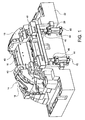
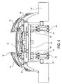
- the first lateral elements 18 of the punch 14 are slidably guided by means of suitable guides (not shown) along respective inclined lateral surfaces 32 formed partly (top part) by the central element 16 of the punch 14 and partly (bottom part) by the support body 22 to be displaced between a moulding position (shown in Figure 4 ), in which these lateral elements are arranged with the respective outer surfaces aligned with the outer surface of the central element 16 so as to define with the latter the inner profile of the part to be moulded, and an ejection position (shown in Figures 1 and 2 ), in which these lateral elements are displaced upwards relative to the central element 16 for ejection of the moulded part.
- Each second lateral element 20 is connected to a respective first lateral element 18 by means of a longitudinal cylindrical guide 34 so as to be drivingly connected for translation with the first lateral element 18 in the vertical direction z, but free to translate relative to the first lateral element 18 in the longitudinal direction x.
- the second lateral elements 20 are moreover slidably guided by means of suitable guides (not shown) along respective inclined lateral surfaces 36 formed by the support body 22.
- the inclinations of the lateral surfaces 32 and 36 will be chosen in each case depending on the dimensions and the geometry of the undercuts of the part to be moulded and in any case may be greater than those permitted by conventional moulds.
- the mould 10 also comprises a plurality of ejection members 38 which may be equally well all of the same type or different from each other (but in any case all known per se) and which are slidably arranged each inside a respective through-hole 40 which extends partly through the support body 22 and partly through the central element 16 of the punch 14.
- the ejection members 38 are four in number in the embodiment shown in the drawings (see in particular Figure 4 ), but their number depends obviously on the specific application, in particular on the number of undercut formations which must be provided on the portion of the part to be moulded, the shape of which is defined by the outer surface of the central element 16 of the punch 14.
- Each ejection member 38 is connected at its bottom end to the extraction plate 30 so as to be displaced vertically in either direction along with the latter.
- the extraction plate 30 is a double plate, with a top plate 30a and a bottom plate 30b which can be moved independently of each other.
- some of the ejection members 38 (in the example shown the longitudinally inner members) are connected to the top plate 30a and are therefore moved together therewith, while the remaining ejection members 38 (in the example shown the longitudinally outer members) are connected to the bottom plate 30b and are therefore moved together therewith.
- the ejection members, and along with them the extraction plate (be it single or double), could also be dispensed with.
- the extraction plate 30 has merely the function of moving the ejection members 38 and not also of moving the first and second lateral elements 18, 20 of the punch 14.
- Linear actuation devices 42 are instead provided for moving the first and second lateral elements 18, 20 of the punch 14, said devices being operatively connected to the first lateral elements 18 so as to control the movement of these elements, and together therewith that of the second lateral elements 20, between the aforementioned moulding and ejection positions.
- the linear actuation devices 42 are four in number and are made as hydraulic jacks each comprising a cylinder 44 fixed to the base plate 24 and a rod 46 connected at its top end to the associated first lateral element 18.
- the rods 46 of the four linear actuation devices 42 are connected at their top end to a support frame 48 (formed for example as a rectangular frame composed of four straight bars) to which the first lateral elements 18 are fixed, whereby the first lateral elements 18 are drivingly connected for translation with each other via the support frame 48.
- a support frame 48 formed for example as a rectangular frame composed of four straight bars
- the first lateral elements 18 are drivingly connected for translation with each other via the support frame 48.
- a different number and/or different types of linear actuation devices may obviously be envisaged with respect to those described and illustrated here.
Landscapes
- Engineering & Computer Science (AREA)
- Manufacturing & Machinery (AREA)
- Mechanical Engineering (AREA)
- Moulds For Moulding Plastics Or The Like (AREA)
- Pens And Brushes (AREA)
- Injection Moulding Of Plastics Or The Like (AREA)
Description
- The present invention relates to a mould for injection-moulding of plastic parts, in particular motor-vehicle parts, such as bumpers. The invention has been conceived, and will be described hereinbelow, with particular reference to a mould for injection-moulding of motor-vehicle bumpers, but it is clear that it is likewise applicable to a mould for injection-moulding of plastic parts of different type and use.
- Conventionally, the moulds for injection-moulding of plastic parts are composed of an outer part, called die, and an inner part, called punch, the die and the punch defining, in the closed condition of the mould, a cavity inside which the plastic material for forming the finished part is injected by a press. In the particular case of moulds intended for the production of motor-vehicle bumpers, the punch is composed in turn of at least three separate elements, i.e. a central element and at least one pair of lateral elements arranged on opposite sides of the central element, the outer surfaces of these three elements defining the inner profile of the aforementioned cavity defined between the punch and the die. The lateral elements are mounted so as to be slidable with respect to the central element along respective inclined lateral surfaces of the latter and, once the mould is opened, they are pushed forwards (i.e. outwards) so as to disengage from projections or undercuts of the moulded part and thus allow release of the moulded part from the punch. In known moulds for injection-moulding of plastic parts, the punch is supported on a base plate by means of a support structure (commonly referred to by the term "trestle") comprising a pair of spacers. A chamber is defined between the spacers of the support structure and slidably receives an extraction plate which is able to move with an alternating movement in the mould opening/closing direction. A linear actuation unit, conventionally of the hydraulic type, controls the movement of the extraction plate. Typically, the mould also comprises ejection members which are slidably arranged inside suitable holes provided in the central element of the punch and have the function of disengaging the punch from projections or undercuts of the moulded part so as to allow release of the latter from the mould. The ejection members are connected to the extraction plate so as to slide inside the respective holes as a result of the translational movement of the extraction plate. The extraction plate is also connected to the movable lateral elements of the punch by means of respective columns guided through respective inclined holes provided in a support body to which the central element of the punch is fixed, whereby the movable lateral elements of the punch move back and forth along with the extraction plate.
- The known structure of the moulds for injection-moulding of plastic parts, as described above, has the disadvantage that the manufacture of the movable components of the mould is complicated and costly and that the punch and the inclined columns are subject, during moulding, to bending and deformation which have a negative effect on the quality of the moulded part.
- A mould of the type indicated above is known, for example, from
FR2809344 - The object of the present invention is to provide a mould for injection-moulding of plastic parts, in particular of motor-vehicle bumpers, which is not affected by the drawbacks of the prior art mentioned above and which in particular is simpler and more compact, has a low weight, can be manufactured at a lower cost and operates in a more flexible and reliable manner compared to the prior art.
- This and other objects are fully achieved according to the present invention by means of a mould for injection-moulding of plastic parts, in particular of motor-vehicle bumpers, having the features defined in the characterizing part of the accompanying independent claim 1.
- Further advantageous features of the present invention are specified in the dependent claims, the contents of which are to be understood as forming an integral and integrating part of the description which follows.
- In short, the invention is based on the idea of providing a mould for injection-moulding of plastic parts, in particular of motor-vehicle bumpers, comprising a die, a punch formed by a stationary central element and by at least two lateral elements movable with respect to the central element, a base plate, a support body mounted on the base plate for supporting, in the closed mould condition, both the punch and the die, a plurality of ejection members slidably received inside respective holes provided in the central element of the punch, and an extraction plate received inside a chamber defined, in the mould opening/closing direction, between the support body and the base plate, the extraction plate being translatable in the mould opening/closing direction and being connected to the ejection members so as to control the sliding movement thereof inside the respective holes, wherein the two movable lateral elements of the punch are connected directly, i.e. without the extraction plate arranged in between, to respective linear actuation devices, such as hydraulic jacks, so as to be moved relative to the central element of the punch.
- Differently from the prior art described above, therefore, according to the invention the lateral elements of the punch are not moved via the extraction plate, for example by means of inclined columns, but are directly moved by the respective linear actuation devices. The extraction plate may therefore have a smaller length compared to the prior art, preferably a length not greater than that of the central element of the punch, with the result that the chamber inside which the extraction plate is received will also have a correspondingly smaller length and therefore the assembly formed by the support body and by the central element of the punch, which in the region of the chamber is subject to bending as a result of its own weight and, during moulding, of the pressure of the plastic material injected into the mould cavity, will be subject to smaller deformations. The mould according to the invention allows therefore to obtain high-quality moulded parts. Moreover, the elimination of the inclined columns allows to simplify the structure of the mould and to reduce the cost thereof compared to the prior art.
- Further features and advantages of the present invention will emerge more clearly from the following detailed description, provided purely by way of a non-limiting example, with reference to the accompanying drawings in which:
-
Figure 1 is a perspective view of the punch of a mould for injection-moulding of plastic parts, in particular of motor-vehicle bumpers, according to a preferred embodiment of the present invention, the punch being shown in the ejection position; -
Figure 2 is a front elevation view of the punch ofFigure 1 ; -
Figure 3 is a top plan view of a mould for injection-moulding of plastic parts, in particular of motor-vehicle bumpers, according to a preferred embodiment of the present invention, the mould being shown without die; -
Figure 4 shows the mould ofFigure 3 cross-sectioned through a longitudinal vertical plane indicated by IV-IV inFigure 3 ; -
Figure 5 shows the mould according toFigure 3 cross-sectioned through a transverse vertical plane indicated by V-V inFigure 3 ; and -
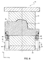
Figure 6 shows the mould ofFigure 3 cross-sectioned through another transverse vertical plane indicated by VI-VI inFigure 3 . - In the description and the claims below, terms such as "vertical" and "horizontal" or "top" and "bottom", are to be understood referring to the installed condition of the mould, where the mould opening/closing direction (indicated "z" in the drawings) is oriented vertically. Moreover, the terms "longitudinal" and "length" on the one hand and "transverse" and "width" on the other hand refer to a pair of horizontal directions perpendicular to each other, oriented in the direction of maximum extension (indicated "x" in the drawings) and in the direction of minimum extension of the mould (indicated "y" in the drawings), respectively.
- With reference to the drawings, a mould for injection-moulding of plastic parts, in the example shown a mould for injection-moulding of motor-vehicle bumpers, is generally indicated 10 and basically comprises a
die 12 and apunch 14 which define a cavity inside which the plastic material shall be injected by a press, in a manner known per se. Thepunch 14 comprises in turn a stationarycentral element 16, a first pair of movable lateral elements 18 (referred to henceforth simply as first lateral elements) arranged on longitudinally opposite sides relative to thecentral element 16, and a second pair of movable lateral elements 20 (referred to henceforth simply as second lateral elements) arranged on longitudinally opposite sides relative to the firstlateral elements 18 and drivingly connected for translation therewith. The outer surfaces of thecentral element 16 and of the first and secondlateral elements die 12, the shape of the moulding cavity and therefore give to the part to be moulded the desired shape. - The
mould 10 also comprises asupport body 22 for supporting both the die 12 and thepunch 14. Thecentral element 16 of thepunch 14 is fixed to thesupport body 22, while thedie 12 and the first and secondlateral elements punch 14 are simply rested, in the closed mould condition, on thesupport body 22. Themould 10 also comprises abase plate 24 on which thesupport body 22 is mounted. Thesupport body 22 has, on its bottom side, acavity 26 which is closed at the bottom by thebase plate 24 so as to form a chamber inside which an extraction plate 30 (visible inFigures 4 and5 ) is arranged in a vertically slidable manner, guided alongvertical columns 28. As can be seen in particular inFigure 4 , preferably thecavity 26, and therefore theextraction plate 30, have a length (longitudinal dimension) not greater than that of thecentral element 16 of thepunch 14. Owing to the smaller length of thecavity 26 compared to the prior art discussed in the introductory part of the present description, it is possible to reduce the projecting part of thesupport body 22 and therefore reduce the deformations to which thesupport body 22 and thecentral element 16 of thepunch 14 are subject both as a result of their own weight and in particular as a result of the pressure exerted during moulding by the plastic material injected into the cavity formed between die 12 andpunch 14. - The first
lateral elements 18 of thepunch 14 are slidably guided by means of suitable guides (not shown) along respective inclinedlateral surfaces 32 formed partly (top part) by thecentral element 16 of thepunch 14 and partly (bottom part) by thesupport body 22 to be displaced between a moulding position (shown inFigure 4 ), in which these lateral elements are arranged with the respective outer surfaces aligned with the outer surface of thecentral element 16 so as to define with the latter the inner profile of the part to be moulded, and an ejection position (shown inFigures 1 and2 ), in which these lateral elements are displaced upwards relative to thecentral element 16 for ejection of the moulded part. Each secondlateral element 20 is connected to a respective firstlateral element 18 by means of a longitudinalcylindrical guide 34 so as to be drivingly connected for translation with the firstlateral element 18 in the vertical direction z, but free to translate relative to the firstlateral element 18 in the longitudinal direction x. The secondlateral elements 20 are moreover slidably guided by means of suitable guides (not shown) along respective inclinedlateral surfaces 36 formed by thesupport body 22. The inclinations of thelateral surfaces - The
mould 10 also comprises a plurality ofejection members 38 which may be equally well all of the same type or different from each other (but in any case all known per se) and which are slidably arranged each inside a respective through-hole 40 which extends partly through thesupport body 22 and partly through thecentral element 16 of thepunch 14. Theejection members 38 are four in number in the embodiment shown in the drawings (see in particularFigure 4 ), but their number depends obviously on the specific application, in particular on the number of undercut formations which must be provided on the portion of the part to be moulded, the shape of which is defined by the outer surface of thecentral element 16 of thepunch 14. Eachejection member 38 is connected at its bottom end to theextraction plate 30 so as to be displaced vertically in either direction along with the latter. More precisely, in the embodiment shown, theextraction plate 30 is a double plate, with atop plate 30a and abottom plate 30b which can be moved independently of each other. In this case, some of the ejection members 38 (in the example shown the longitudinally inner members) are connected to thetop plate 30a and are therefore moved together therewith, while the remaining ejection members 38 (in the example shown the longitudinally outer members) are connected to thebottom plate 30b and are therefore moved together therewith. Obviously, in the case of parts to be moulded devoid of bosses or undercuts in their central part, the ejection members, and along with them the extraction plate (be it single or double), could also be dispensed with. - Differently from the prior art discussed above, the
extraction plate 30 has merely the function of moving theejection members 38 and not also of moving the first and secondlateral elements punch 14.Linear actuation devices 42 are instead provided for moving the first and secondlateral elements punch 14, said devices being operatively connected to the firstlateral elements 18 so as to control the movement of these elements, and together therewith that of the secondlateral elements 20, between the aforementioned moulding and ejection positions. In the embodiment shown, thelinear actuation devices 42 are four in number and are made as hydraulic jacks each comprising acylinder 44 fixed to thebase plate 24 and arod 46 connected at its top end to the associated firstlateral element 18. More specifically, therods 46 of the fourlinear actuation devices 42 are connected at their top end to a support frame 48 (formed for example as a rectangular frame composed of four straight bars) to which the firstlateral elements 18 are fixed, whereby the firstlateral elements 18 are drivingly connected for translation with each other via thesupport frame 48. However, a different number and/or different types of linear actuation devices may obviously be envisaged with respect to those described and illustrated here.
Claims (7)
- Mould (10) for injection-moulding of plastic parts, in particular motor-vehicle parts, comprising a die (12) and a punch (14) displaceable with respect to each other along an opening/closing direction (z) between a closed mould position, in which they define a cavity intended to receive plastic material injected by a press, and an open mould position, in which they are spaced from each other by an amount such as to allow ejection of the moulded plastic part,
wherein the punch (14) comprises a stationary central element (16) having an outer surface and a pair of lateral surfaces (32) inclined relative to the opening/closing direction (z), as well as a pair of first movable lateral elements (18) arranged on longitudinally opposite sides relative to the central element (16) and having respective outer surfaces, the outer surfaces of the central element (16) and of the first lateral elements (18) of the punch (14) being suitably shaped to define the profile of the plastic part to be moulded,
wherein each of the first lateral elements (18) of the punch (14) is slidably guided along the respective inclined lateral surface (32) of the central element (16) of the punch (14) to be displaced between a moulding position, in which the outer surface of the lateral element (18) is aligned with the outer surface of the central element (16), and an ejection position, in which the outer surface of the lateral element (18) projects outwards with respect to the outer surface of the central element (16) for ejection of the moulded part,
wherein the mould (10) further comprises a plurality of linear actuation devices (42) arranged to control the movement of the first lateral elements (18) of the punch (14) relative to the central element (16) between the aforementioned moulding and ejection positions, and
wherein the mould (10) further comprises a plurality of ejection members (38) slidably received inside respective holes (40) provided in the central element (16) of the punch (14), and an extraction plate (30, 30a, 30b) which is translatable in the mould opening/closing direction and is connected to the ejection members (38) to control the sliding movement thereof inside the respective holes (40),
the mould (10) being characterized in that the linear actuation devices (42) are connected to the first lateral elements (18) of the punch (14) without the extraction plate (30, 30a, 30b) being arranged in between. - Mould according to Claim 1, wherein the linear actuation devices (42) are hydraulic jacks.
- Mould according to Claim 1 or Claim 2, wherein the linear actuation devices (42) each comprise a respective expulsion member (46) movable in a direction parallel to the opening/closing direction (z).
- Mould according to Claim 3, further comprising a support frame (48) to which the first lateral elements (18) are fixed, the expulsion members (46) of the linear actuation devices (42) being each connected to the support frame (48) so as to be drivingly connected to each other in the movement along the opening/closing direction (z).
- Mould according to any one of the preceding claims, wherein the punch (14) further comprises a pair of second lateral elements (20) arranged on longitudinally opposite sides with respect to the first lateral elements (18), wherein each second lateral element (20) is connected to a respective first lateral element (18) so as to be drivingly connected for translation with the latter in the opening/closing direction (z), but free to translate relative to the latter in a longitudinal direction (x) of the mould.
- Mould according to any one of the preceding claims, further comprising a base plate (24) and a support body (22) mounted on the base plate (24) to support, in the closed mould condition, both the punch (14) and the die (12), the support body (22) and the base plate (24) enclosing a chamber (26) inside which the extraction plate (30, 30a, 30b) is arranged.
- Mould according to Claim 6, wherein the length or longitudinal dimension of the chamber (26) is not greater than that of the central element (16) of the punch (14).
Applications Claiming Priority (2)
| Application Number | Priority Date | Filing Date | Title |
|---|---|---|---|
| ITTO2010A000066A IT1398402B1 (en) | 2010-01-29 | 2010-01-29 | MOLD FOR INJECTION MOLDING OF PLASTIC PARTS. |
| PCT/IB2011/050373 WO2011092650A1 (en) | 2010-01-29 | 2011-01-28 | Mould for injection-moulding of plastic parts |
Publications (2)
| Publication Number | Publication Date |
|---|---|
| EP2528722A1 EP2528722A1 (en) | 2012-12-05 |
| EP2528722B1 true EP2528722B1 (en) | 2013-12-11 |
Family
ID=42671888
Family Applications (1)
| Application Number | Title | Priority Date | Filing Date |
|---|---|---|---|
| EP11709469.8A Not-in-force EP2528722B1 (en) | 2010-01-29 | 2011-01-28 | Mould for injection-moulding of plastic parts |
Country Status (8)
| Country | Link |
|---|---|
| US (1) | US20130129857A1 (en) |
| EP (1) | EP2528722B1 (en) |
| BR (1) | BR112012018977A2 (en) |
| CA (1) | CA2786177A1 (en) |
| ES (1) | ES2451580T3 (en) |
| IT (1) | IT1398402B1 (en) |
| RU (1) | RU2012136837A (en) |
| WO (1) | WO2011092650A1 (en) |
Families Citing this family (1)
| Publication number | Priority date | Publication date | Assignee | Title |
|---|---|---|---|---|
| FR3038248B1 (en) * | 2015-07-02 | 2017-12-22 | Reydel Automotive Bv | METHOD AND DEVICE FOR MANUFACTURING A HYBRID OR COMPOSITE PART BASED ON THERMOPLASTIC MATERIAL HAVING A FACE OF APPEARANCE AND A TECHNICAL FACE |
Family Cites Families (3)
| Publication number | Priority date | Publication date | Assignee | Title |
|---|---|---|---|---|
| FR2809344B1 (en) * | 2000-05-24 | 2002-08-23 | Ecia Equip Composants Ind Auto | DEFORMING DEMOLDING INJECTION MOLD |
| JP4774878B2 (en) * | 2005-09-08 | 2011-09-14 | マツダ株式会社 | Injection molding product manufacturing apparatus and manufacturing method thereof |
| WO2008084128A1 (en) * | 2007-01-10 | 2008-07-17 | Mecanoplastica, S.A. | Apparatus and method for releasing plastic parts from a mould by forward ejection |
-
2010
- 2010-01-29 IT ITTO2010A000066A patent/IT1398402B1/en active
-
2011
- 2011-01-28 RU RU2012136837/05A patent/RU2012136837A/en not_active Application Discontinuation
- 2011-01-28 WO PCT/IB2011/050373 patent/WO2011092650A1/en not_active Ceased
- 2011-01-28 ES ES11709469.8T patent/ES2451580T3/en active Active
- 2011-01-28 EP EP11709469.8A patent/EP2528722B1/en not_active Not-in-force
- 2011-01-28 US US13/521,068 patent/US20130129857A1/en not_active Abandoned
- 2011-01-28 BR BR112012018977A patent/BR112012018977A2/en not_active IP Right Cessation
- 2011-01-28 CA CA2786177A patent/CA2786177A1/en not_active Abandoned
Also Published As
| Publication number | Publication date |
|---|---|
| ES2451580T3 (en) | 2014-03-27 |
| ITTO20100066A1 (en) | 2011-07-30 |
| BR112012018977A2 (en) | 2018-03-27 |
| US20130129857A1 (en) | 2013-05-23 |
| WO2011092650A1 (en) | 2011-08-04 |
| CA2786177A1 (en) | 2011-04-08 |
| IT1398402B1 (en) | 2013-02-22 |
| RU2012136837A (en) | 2014-03-10 |
| EP2528722A1 (en) | 2012-12-05 |
Similar Documents
| Publication | Publication Date | Title |
|---|---|---|
| RU2385227C2 (en) | Tool for injection moulding of plastics | |
| JP2009208091A (en) | Molding apparatus | |
| EP3326780B1 (en) | Undercut processing mechanism and molding die | |
| EP2454068B1 (en) | A mould for the injection moulding of elements with undercuts made of plastic material, with an integrated ejection system | |
| US20130129857A1 (en) | Mould for injection-moulding of plastic parts | |
| EP0949022A1 (en) | Casting tooling | |
| US20090121387A1 (en) | Apparatus and Method for Manufacturing Plastic Products | |
| JP6968863B2 (en) | Press to extrude metallic material directly | |
| CN112606339B (en) | Undercut demoulding mechanism and injection mold | |
| EP4091738B1 (en) | Apparatus and method for forming material | |
| JP2008525238A (en) | Mold and product molding method | |
| KR102037620B1 (en) | Manufacturing Method of Retaining Platen for Resin Molding Device, Resin Molding Device and Retaining Platen for Resin Molding Device | |
| CN112026115A (en) | A structure that can control the core pulling sequence of the fixed die slider when the die is opened and closed | |
| ITMI20090056A1 (en) | PRESS FOR HOT MOLDING OF BILLETS AND THE LIKE. | |
| KR100628552B1 (en) | Press Molding Machine | |
| KR101946240B1 (en) | Common use for refrigerator case | |
| KR100934616B1 (en) | Foam mold of refrigerator case | |
| CN212242003U (en) | A structure that can control the core pulling sequence of the fixed die slider when the die is opened and closed | |
| KR101442116B1 (en) | ejector for vertical insert injectoin molding machine | |
| KR20120087729A (en) | mold apparatus for forming cooking vessel | |
| CN102328415B (en) | Longitudinal cylinder drive and duplex sliding block inclined core-loosening device arranged inside moving die | |
| US1708178A (en) | Press for forming plastic articles | |
| CN101132899A (en) | Mold and method for forming plastic product | |
| JP6015495B2 (en) | Powder molding equipment | |
| CN209141367U (en) | A kind of ejecting mechanism of mobile phone shell processing mold |
Legal Events
| Date | Code | Title | Description |
|---|---|---|---|
| PUAI | Public reference made under article 153(3) epc to a published international application that has entered the european phase |
Free format text: ORIGINAL CODE: 0009012 |
|
| 17P | Request for examination filed |
Effective date: 20120802 |
|
| AK | Designated contracting states |
Kind code of ref document: A1 Designated state(s): AL AT BE BG CH CY CZ DE DK EE ES FI FR GB GR HR HU IE IS IT LI LT LU LV MC MK MT NL NO PL PT RO RS SE SI SK SM TR |
|
| DAX | Request for extension of the european patent (deleted) | ||
| GRAP | Despatch of communication of intention to grant a patent |
Free format text: ORIGINAL CODE: EPIDOSNIGR1 |
|
| INTG | Intention to grant announced |
Effective date: 20130627 |
|
| GRAS | Grant fee paid |
Free format text: ORIGINAL CODE: EPIDOSNIGR3 |
|
| GRAA | (expected) grant |
Free format text: ORIGINAL CODE: 0009210 |
|
| RAP1 | Party data changed (applicant data changed or rights of an application transferred) |
Owner name: H.C.M. STAMPI S.R.L. |
|
| AK | Designated contracting states |
Kind code of ref document: B1 Designated state(s): AL AT BE BG CH CY CZ DE DK EE ES FI FR GB GR HR HU IE IS IT LI LT LU LV MC MK MT NL NO PL PT RO RS SE SI SK SM TR |
|
| REG | Reference to a national code |
Ref country code: GB Ref legal event code: FG4D |
|
| REG | Reference to a national code |
Ref country code: CH Ref legal event code: EP |
|
| REG | Reference to a national code |
Ref country code: AT Ref legal event code: REF Ref document number: 644253 Country of ref document: AT Kind code of ref document: T Effective date: 20140115 |
|
| REG | Reference to a national code |
Ref country code: IE Ref legal event code: FG4D |
|
| REG | Reference to a national code |
Ref country code: DE Ref legal event code: R096 Ref document number: 602011004170 Country of ref document: DE Effective date: 20140206 |
|
| REG | Reference to a national code |
Ref country code: SE Ref legal event code: TRGR |
|
| REG | Reference to a national code |
Ref country code: ES Ref legal event code: FG2A Ref document number: 2451580 Country of ref document: ES Kind code of ref document: T3 Effective date: 20140327 |
|
| REG | Reference to a national code |
Ref country code: NL Ref legal event code: VDEP Effective date: 20131211 |
|
| REG | Reference to a national code |
Ref country code: AT Ref legal event code: MK05 Ref document number: 644253 Country of ref document: AT Kind code of ref document: T Effective date: 20131211 |
|
| PG25 | Lapsed in a contracting state [announced via postgrant information from national office to epo] |
Ref country code: HR Free format text: LAPSE BECAUSE OF FAILURE TO SUBMIT A TRANSLATION OF THE DESCRIPTION OR TO PAY THE FEE WITHIN THE PRESCRIBED TIME-LIMIT Effective date: 20131211 Ref country code: LT Free format text: LAPSE BECAUSE OF FAILURE TO SUBMIT A TRANSLATION OF THE DESCRIPTION OR TO PAY THE FEE WITHIN THE PRESCRIBED TIME-LIMIT Effective date: 20131211 Ref country code: NO Free format text: LAPSE BECAUSE OF FAILURE TO SUBMIT A TRANSLATION OF THE DESCRIPTION OR TO PAY THE FEE WITHIN THE PRESCRIBED TIME-LIMIT Effective date: 20140311 Ref country code: FI Free format text: LAPSE BECAUSE OF FAILURE TO SUBMIT A TRANSLATION OF THE DESCRIPTION OR TO PAY THE FEE WITHIN THE PRESCRIBED TIME-LIMIT Effective date: 20131211 Ref country code: NL Free format text: LAPSE BECAUSE OF FAILURE TO SUBMIT A TRANSLATION OF THE DESCRIPTION OR TO PAY THE FEE WITHIN THE PRESCRIBED TIME-LIMIT Effective date: 20131211 |
|
| REG | Reference to a national code |
Ref country code: LT Ref legal event code: MG4D |
|
| PG25 | Lapsed in a contracting state [announced via postgrant information from national office to epo] |
Ref country code: RS Free format text: LAPSE BECAUSE OF FAILURE TO SUBMIT A TRANSLATION OF THE DESCRIPTION OR TO PAY THE FEE WITHIN THE PRESCRIBED TIME-LIMIT Effective date: 20131211 Ref country code: LV Free format text: LAPSE BECAUSE OF FAILURE TO SUBMIT A TRANSLATION OF THE DESCRIPTION OR TO PAY THE FEE WITHIN THE PRESCRIBED TIME-LIMIT Effective date: 20131211 Ref country code: CY Free format text: LAPSE BECAUSE OF FAILURE TO SUBMIT A TRANSLATION OF THE DESCRIPTION OR TO PAY THE FEE WITHIN THE PRESCRIBED TIME-LIMIT Effective date: 20131211 Ref country code: AT Free format text: LAPSE BECAUSE OF FAILURE TO SUBMIT A TRANSLATION OF THE DESCRIPTION OR TO PAY THE FEE WITHIN THE PRESCRIBED TIME-LIMIT Effective date: 20131211 |
|
| PG25 | Lapsed in a contracting state [announced via postgrant information from national office to epo] |
Ref country code: IS Free format text: LAPSE BECAUSE OF FAILURE TO SUBMIT A TRANSLATION OF THE DESCRIPTION OR TO PAY THE FEE WITHIN THE PRESCRIBED TIME-LIMIT Effective date: 20140411 Ref country code: BE Free format text: LAPSE BECAUSE OF FAILURE TO SUBMIT A TRANSLATION OF THE DESCRIPTION OR TO PAY THE FEE WITHIN THE PRESCRIBED TIME-LIMIT Effective date: 20131211 Ref country code: EE Free format text: LAPSE BECAUSE OF FAILURE TO SUBMIT A TRANSLATION OF THE DESCRIPTION OR TO PAY THE FEE WITHIN THE PRESCRIBED TIME-LIMIT Effective date: 20131211 |
|
| PG25 | Lapsed in a contracting state [announced via postgrant information from national office to epo] |
Ref country code: PT Free format text: LAPSE BECAUSE OF FAILURE TO SUBMIT A TRANSLATION OF THE DESCRIPTION OR TO PAY THE FEE WITHIN THE PRESCRIBED TIME-LIMIT Effective date: 20140411 Ref country code: PL Free format text: LAPSE BECAUSE OF FAILURE TO SUBMIT A TRANSLATION OF THE DESCRIPTION OR TO PAY THE FEE WITHIN THE PRESCRIBED TIME-LIMIT Effective date: 20131211 Ref country code: RO Free format text: LAPSE BECAUSE OF FAILURE TO SUBMIT A TRANSLATION OF THE DESCRIPTION OR TO PAY THE FEE WITHIN THE PRESCRIBED TIME-LIMIT Effective date: 20131211 Ref country code: SK Free format text: LAPSE BECAUSE OF FAILURE TO SUBMIT A TRANSLATION OF THE DESCRIPTION OR TO PAY THE FEE WITHIN THE PRESCRIBED TIME-LIMIT Effective date: 20131211 Ref country code: LU Free format text: LAPSE BECAUSE OF FAILURE TO SUBMIT A TRANSLATION OF THE DESCRIPTION OR TO PAY THE FEE WITHIN THE PRESCRIBED TIME-LIMIT Effective date: 20140128 |
|
| REG | Reference to a national code |
Ref country code: CH Ref legal event code: PL |
|
| REG | Reference to a national code |
Ref country code: DE Ref legal event code: R097 Ref document number: 602011004170 Country of ref document: DE |
|
| PG25 | Lapsed in a contracting state [announced via postgrant information from national office to epo] |
Ref country code: MC Free format text: LAPSE BECAUSE OF FAILURE TO SUBMIT A TRANSLATION OF THE DESCRIPTION OR TO PAY THE FEE WITHIN THE PRESCRIBED TIME-LIMIT Effective date: 20131211 |
|
| PLBE | No opposition filed within time limit |
Free format text: ORIGINAL CODE: 0009261 |
|
| STAA | Information on the status of an ep patent application or granted ep patent |
Free format text: STATUS: NO OPPOSITION FILED WITHIN TIME LIMIT |
|
| PG25 | Lapsed in a contracting state [announced via postgrant information from national office to epo] |
Ref country code: LI Free format text: LAPSE BECAUSE OF NON-PAYMENT OF DUE FEES Effective date: 20140131 Ref country code: DK Free format text: LAPSE BECAUSE OF FAILURE TO SUBMIT A TRANSLATION OF THE DESCRIPTION OR TO PAY THE FEE WITHIN THE PRESCRIBED TIME-LIMIT Effective date: 20131211 Ref country code: CH Free format text: LAPSE BECAUSE OF NON-PAYMENT OF DUE FEES Effective date: 20140131 |
|
| REG | Reference to a national code |
Ref country code: IE Ref legal event code: MM4A |
|
| 26N | No opposition filed |
Effective date: 20140912 |
|
| REG | Reference to a national code |
Ref country code: DE Ref legal event code: R097 Ref document number: 602011004170 Country of ref document: DE Effective date: 20140912 |
|
| PG25 | Lapsed in a contracting state [announced via postgrant information from national office to epo] |
Ref country code: IE Free format text: LAPSE BECAUSE OF NON-PAYMENT OF DUE FEES Effective date: 20140128 |
|
| PG25 | Lapsed in a contracting state [announced via postgrant information from national office to epo] |
Ref country code: SI Free format text: LAPSE BECAUSE OF FAILURE TO SUBMIT A TRANSLATION OF THE DESCRIPTION OR TO PAY THE FEE WITHIN THE PRESCRIBED TIME-LIMIT Effective date: 20131211 |
|
| REG | Reference to a national code |
Ref country code: FR Ref legal event code: PLFP Year of fee payment: 6 |
|
| PG25 | Lapsed in a contracting state [announced via postgrant information from national office to epo] |
Ref country code: MT Free format text: LAPSE BECAUSE OF FAILURE TO SUBMIT A TRANSLATION OF THE DESCRIPTION OR TO PAY THE FEE WITHIN THE PRESCRIBED TIME-LIMIT Effective date: 20131211 |
|
| PG25 | Lapsed in a contracting state [announced via postgrant information from national office to epo] |
Ref country code: SM Free format text: LAPSE BECAUSE OF FAILURE TO SUBMIT A TRANSLATION OF THE DESCRIPTION OR TO PAY THE FEE WITHIN THE PRESCRIBED TIME-LIMIT Effective date: 20131211 |
|
| PG25 | Lapsed in a contracting state [announced via postgrant information from national office to epo] |
Ref country code: BG Free format text: LAPSE BECAUSE OF FAILURE TO SUBMIT A TRANSLATION OF THE DESCRIPTION OR TO PAY THE FEE WITHIN THE PRESCRIBED TIME-LIMIT Effective date: 20131211 Ref country code: GR Free format text: LAPSE BECAUSE OF FAILURE TO SUBMIT A TRANSLATION OF THE DESCRIPTION OR TO PAY THE FEE WITHIN THE PRESCRIBED TIME-LIMIT Effective date: 20140312 |
|
| PG25 | Lapsed in a contracting state [announced via postgrant information from national office to epo] |
Ref country code: TR Free format text: LAPSE BECAUSE OF FAILURE TO SUBMIT A TRANSLATION OF THE DESCRIPTION OR TO PAY THE FEE WITHIN THE PRESCRIBED TIME-LIMIT Effective date: 20131211 Ref country code: HU Free format text: LAPSE BECAUSE OF FAILURE TO SUBMIT A TRANSLATION OF THE DESCRIPTION OR TO PAY THE FEE WITHIN THE PRESCRIBED TIME-LIMIT; INVALID AB INITIO Effective date: 20110128 |
|
| REG | Reference to a national code |
Ref country code: FR Ref legal event code: PLFP Year of fee payment: 7 |
|
| REG | Reference to a national code |
Ref country code: FR Ref legal event code: PLFP Year of fee payment: 8 |
|
| PG25 | Lapsed in a contracting state [announced via postgrant information from national office to epo] |
Ref country code: MK Free format text: LAPSE BECAUSE OF FAILURE TO SUBMIT A TRANSLATION OF THE DESCRIPTION OR TO PAY THE FEE WITHIN THE PRESCRIBED TIME-LIMIT Effective date: 20131211 |
|
| PG25 | Lapsed in a contracting state [announced via postgrant information from national office to epo] |
Ref country code: AL Free format text: LAPSE BECAUSE OF FAILURE TO SUBMIT A TRANSLATION OF THE DESCRIPTION OR TO PAY THE FEE WITHIN THE PRESCRIBED TIME-LIMIT Effective date: 20131211 |
|
| PGFP | Annual fee paid to national office [announced via postgrant information from national office to epo] |
Ref country code: CZ Payment date: 20181126 Year of fee payment: 9 |
|
| PGFP | Annual fee paid to national office [announced via postgrant information from national office to epo] |
Ref country code: FR Payment date: 20190131 Year of fee payment: 9 Ref country code: ES Payment date: 20190201 Year of fee payment: 9 Ref country code: GB Payment date: 20190121 Year of fee payment: 9 Ref country code: IT Payment date: 20181126 Year of fee payment: 9 |
|
| PGFP | Annual fee paid to national office [announced via postgrant information from national office to epo] |
Ref country code: SE Payment date: 20190116 Year of fee payment: 9 |
|
| PGFP | Annual fee paid to national office [announced via postgrant information from national office to epo] |
Ref country code: DE Payment date: 20190401 Year of fee payment: 9 |
|
| REG | Reference to a national code |
Ref country code: DE Ref legal event code: R119 Ref document number: 602011004170 Country of ref document: DE |
|
| REG | Reference to a national code |
Ref country code: SE Ref legal event code: EUG |
|
| GBPC | Gb: european patent ceased through non-payment of renewal fee |
Effective date: 20200128 |
|
| REG | Reference to a national code |
Ref country code: SE Ref legal event code: EUG |
|
| PG25 | Lapsed in a contracting state [announced via postgrant information from national office to epo] |
Ref country code: CZ Free format text: LAPSE BECAUSE OF NON-PAYMENT OF DUE FEES Effective date: 20200128 Ref country code: DE Free format text: LAPSE BECAUSE OF NON-PAYMENT OF DUE FEES Effective date: 20200801 Ref country code: SE Free format text: LAPSE BECAUSE OF NON-PAYMENT OF DUE FEES Effective date: 20200129 Ref country code: GB Free format text: LAPSE BECAUSE OF NON-PAYMENT OF DUE FEES Effective date: 20200128 Ref country code: FR Free format text: LAPSE BECAUSE OF NON-PAYMENT OF DUE FEES Effective date: 20200131 |
|
| PG25 | Lapsed in a contracting state [announced via postgrant information from national office to epo] |
Ref country code: IT Free format text: LAPSE BECAUSE OF NON-PAYMENT OF DUE FEES Effective date: 20200128 |
|
| REG | Reference to a national code |
Ref country code: ES Ref legal event code: FD2A Effective date: 20210607 |
|
| PG25 | Lapsed in a contracting state [announced via postgrant information from national office to epo] |
Ref country code: ES Free format text: LAPSE BECAUSE OF NON-PAYMENT OF DUE FEES Effective date: 20200129 |