EP2528285B1 - Zugangsverfahren, system und vorrichtung - Google Patents
Zugangsverfahren, system und vorrichtung Download PDFInfo
- Publication number
- EP2528285B1 EP2528285B1 EP10791183.6A EP10791183A EP2528285B1 EP 2528285 B1 EP2528285 B1 EP 2528285B1 EP 10791183 A EP10791183 A EP 10791183A EP 2528285 B1 EP2528285 B1 EP 2528285B1
- Authority
- EP
- European Patent Office
- Prior art keywords
- sub
- wan
- connection
- cpe
- mid
- Prior art date
- Legal status (The legal status is an assumption and is not a legal conclusion. Google has not performed a legal analysis and makes no representation as to the accuracy of the status listed.)
- Active
Links
Images

Classifications
-
- H—ELECTRICITY
- H04—ELECTRIC COMMUNICATION TECHNIQUE
- H04L—TRANSMISSION OF DIGITAL INFORMATION, e.g. TELEGRAPHIC COMMUNICATION
- H04L12/00—Data switching networks
- H04L12/54—Store-and-forward switching systems
- H04L12/56—Packet switching systems
- H04L12/5691—Access to open networks; Ingress point selection, e.g. ISP selection
- H04L12/5692—Selection among different networks
-
- H—ELECTRICITY
- H04—ELECTRIC COMMUNICATION TECHNIQUE
- H04L—TRANSMISSION OF DIGITAL INFORMATION, e.g. TELEGRAPHIC COMMUNICATION
- H04L67/00—Network arrangements or protocols for supporting network services or applications
- H04L67/14—Session management
-
- H—ELECTRICITY
- H04—ELECTRIC COMMUNICATION TECHNIQUE
- H04L—TRANSMISSION OF DIGITAL INFORMATION, e.g. TELEGRAPHIC COMMUNICATION
- H04L12/00—Data switching networks
- H04L12/28—Data switching networks characterised by path configuration, e.g. LAN [Local Area Networks] or WAN [Wide Area Networks]
- H04L12/2803—Home automation networks
- H04L2012/284—Home automation networks characterised by the type of medium used
- H04L2012/2841—Wireless
Definitions
- the present invention relates to the field of digital home, and in particular to an access method, an access system and an access device.
- Future family will be a networked and informationized family; the external is connected with a high-speed digital communication line and the internal controls information household appliances with different functions through a home server.
- a home network many household appliances can be operated and controlled. When people are away from home, they can manipulate many kinds of household appliances in their houses through the communication mode of home network, for example, open an automatic curtain or turn off a micro oven.
- a user can observe images transmitted from a digital camera or a camera installed on a door through a small window on the screen of the computer, thereby confirming who the knocker is; if there is any unusual conditions, the user can send out alarm information. In the same way, information also can be transmitted among all kinds of household appliances through the home network.
- home office would become a tendency in future, and home would become a more comfortable office environment; people can keep a connection with a computer network of a company using their own laptops at any place anytime, perform data communication anytime and anywhere and use peripheral devices such as printer and projector, needing no cable to keep the communication state.
- the implementation and application of all these wonderful prospects are based on a smooth communication between the home network and an external Wide Area Network (WAN).
- WAN Wide Area Network
- a communication between the home network and the external WAN is instable, it is very difficult to guarantee the quality of the home office and home online entertainments, thus the user experience is greatly impacted.
- Most people have suffered an embarrassment when surfing the Internet that the network speed is very slow or the network is not able to be accessed due to a network fault, even suffered a condition that an emergency needing to be dealt with is delayed due to a network fault.
- the WAN comprises a mobile communication network, the Internet and so on.
- the present digital home product accesses the WAN through a single access mode, generally through wireless access or wired access.
- There are few digital home products simultaneously supporting both the wired access and the wireless access which brings a great inconvenience or limit to users and is difficult to provide a sufficient guarantee for the stability and speed of the home network communication. Therefore, there exists a strong need 5 of a method and a system for processing home information, which can support both the wired access and the wireless access.
- EP 0 986 285 A2 discloses a system and method for implementing a backup line in a telecommunication network.
- the present invention provides an access system as defined in claim 1, an access method as defined in claim 4, a CPE device as defined in claim 8 and a MID device as defined in claim 9. Further advantageous aspects of the present invention are set out in the dependent claims.
- a WAN access mode with mutual standby for a home information processing system which supports both the wired access and wireless access to the WAN. Since two different access modes are adopted at the WAN side and it is very unlikely that the two different modes have a failure simultaneously, a stable network connection and certain bandwidth can be provided for a home user at the WAN through the home information processing system and method. Thus, a digital home user has no need to worry about the trouble and embarrassment of no access to a network caused by an instable wireless network or a wired-connection line failure.
- the MID sub-system can be inserted into the CPE sub-system, or can be separated from the CPE sub-system; through this separable and combinable structure, a great convenience is brought to users and the product experience of users is more humanized.
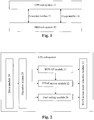
- FIG. 1 shows a structure diagram of the access system in accordance with the embodiment of the present invention.
- the system comprises: a CPE sub-system 11, an MID sub-system 12 and a connection interface 13, wherein the CPE sub-system 11 is configured to receive a connection request for carrying out a data connection with a WAN, and send the connection request to the MID sub-system 12 through the connection interface 13 when determining that the CPE sub-system itself 11 is not able to carry out a wired connection with the WAN, so that a wireless connection is carried out with the WAN through the MID sub-system; the MID sub-system 12 is configured to receive a connection request for carrying out a data connection with the WAN, and send the connection request to the CPE sub-system 11 through the connection interface 13 when determining that the MID sub-system itself 12 is not able to carry out a wireless connection with the WAN, so that a wired connection is carried out with the WAN through
- the CPE sub-system 11 is further configured to carry out a wired connection with the WAN, specifically in a mode of PPPoE.
- the MID sub-system 12 is further configured to carry out a wireless connection with the WAN, specifically in a mode of PPP.
- the system further comprises:
- Fig. 2 shows a structure diagram of a CPE sub-system in accordance with an embodiment of the present invention.
- the CPE sub-system comprises: a WiFi AP module 21, a PPPoE access module 22, a WAN access mode selection module 23, wherein the PPPoE access module 22 is configured to carry out a wired broadband access to a WAN in a wired connection mode through a WAN port by the CPE sub-system;
- the WAN access mode selection module 23 is configured to receive a connection request for carrying out a data connection with the WAN, and send the connection request to the WiFi AP module 21 through the WiFi interface when determining that the CPE sub-system is not able to carry out a wired connection with the WAN;
- the WiFi AP module 21 is configured to provide wireless coverage carried out in a WiFi mode to enable the MID sub-system having a WiFi Client module to access the CPE sub-system,
- the WiFi AP module 21 is further configured to trigger the PPPoE access module 22 after receiving, from the MID sub-system, a connection request for carrying out a data connection with the WAN.
- the CPE sub-system can further comprise: a drive module 24, an operation system 25 and a user setting module 26, wherein the drive module 24 is configured to provide an interface between a hardware device and the operation system 25, wherein the operation system 25 can only control the operation of the hardware device through an interface function provided by the drive module 24;
- the interface function comprises a charge enable function, a charge disable function, a WiFi interface enable function, a WiFi interface disable function and the like;
- the hardware device comprises: a charge interface, a WiFi interface and the like; when the WiFi interface is enabled, the CPE sub-system provides wireless coverage carried out in a WiFi mode; when the WiFi interface is disabled, the CPE sub-system is not able to provide the wireless coverage carried out in a WiFi mode; when the WiFi interface is disabled, other devices having a WiFi Client is not able to be connected with the CPE sub-system through the WiFi AP, because the CPE sub-system has disabled the WiFi interface; the operation system 25 is configured to control the operation of the entire CPE sub-system and the management of other modules
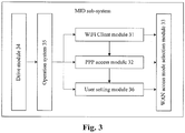
- Fig. 3 shows a structure diagram of an MID sub-system in accordance with an embodiment of the present invention.
- the MID sub-system comprises: a WiFi Client module 31, a PPP access module 32 and a WAN access mode selection module 33, wherein the PPP access module 32 is configured to carry out a wireless access to a WAN through a wireless data card by the MID sub-system, wherein there can be various modes of the wireless data card, for example, Wideband Code Division Multiple Access (WCDMA), Code Division Multiple Access (CDMA) 2000, Time Division-Synchronization Code Division Multiple Access (TD-SCDMA), Worldwide Interoperability for Microwave Access (WiMAX), Long Term Evolution (LTE) and the like;
- the WAN access mode selection module 33 is configured to receive a connection request for carrying out a data connection with the WAN, and send the connection request to the WiFi Client module 31 when determining that
- the WiFi Client module 31 is further configured to trigger the PPP access module 32 after receiving, from the CPE sub-system, a connection request for carrying out a data connection with the WAN.
- the MID sub-system can further comprise: a drive module 34, an operation system 35 and a user setting module 36, wherein the drive module 34 is configured to provide an interface between a hardware device and the operation system 35, wherein the operation system 35 can only control the operation of the hardware device through an interface function provided by the drive module 34;
- the interface function comprises a charge enable function, a charge disable function, a WiFi interface enable function, a WiFi interface disable function and the like;
- the hardware device comprises: a charge interface, a WiFi interface and the like; when the WiFi interface is enabled, the MID sub-system is able to realize a wireless connection with the CPE sub-system in a WiFi mode; when the WiFi interface is disabled, the MID sub-system is not able to realize the wireless connection with the CPE sub-system in a WiFi mode;
- the operation system 35 is configured to control the operation of the entire MID sub-system and the management of other modules in the MID sub-system, wherein the operation system of the MID sub-system generally adopts operation systems such
- the CPE sub-system receives a connection request for carrying out a data connection with a WAN, sends the connection request to the MID sub-system through the connection interface when determining that the CPE sub-system itself is not able to carry out a wired connection with the WAN, so that a wireless connection is carried out with the WAN through the MID sub-system; and the MID sub-system receives a connection request for carrying out a data connection with the WAN, and sends the connection request to the CPE sub-system through the connection interface when determining that the MID sub-system itself is not able to carry out a wireless connection with the WAN, so that a wired connection is carried out with the WAN through the CPE sub-system.
- Fig. 4 shows a flowchart of a method for a CPE sub-system accessing a WAN in accordance with an embodiment of the present invention.
- the method for the CPE sub-system accessing the WAN in accordance with the embodiment of the present invention comprises the steps as follows.
- Step 401 the CPE sub-system receives a connection request for carrying out a data connection with the WAN.
- the CPE sub-system receives a connection request for carrying out a data connection with the WAN, from a device, connected with the CPE sub-system, requesting access to a network. Since the CPE sub-system can provide wireless coverage carried out in a WiFi mode, only devices with a WiFi Client can be connected to the CPE sub-system; thus, the device, connected with the CPE sub-system, requesting access to a network must have a WiFi Client, wherein the WiFi Client is connected with the CPE sub-system through a WiFi AP.
- the device, connected with the CPE sub-system, requesting access to a network is, for example, a PC with the WiFi Client or a mobile terminal with the WiFi Client.
- Step 402 it is judged whether the wired access of the WAN connected with the CPE sub-system has been disabled; if so, execute Step 403; otherwise, execute Step 405.
- the CPE sub-system judges whether the wired access of the WAN connected with the CPE sub-system itself has been disabled; if so, execute Step 403; otherwise, execute Step 405, wherein the basis for the CPE sub-system judging whether the wired access of the WAN connected with the CPE sub-system itself has been disabled is: a parameter stored in a memory when a user sets whether to disable the wired access of the WAN connected with the CPE sub-system.
- Step 403 the CPE sub-system judges whether the wireless connection of the WAN connected with an MID sub-system has been disabled; if so, execute Step 407; otherwise, execute Sep 404.
- the basis for the CPE sub-system judging whether the wireless connection of the WAN connected with the MID sub-system has been disabled is: a parameter stored in a memory when a user sets whether to disable the wireless access of the WAN connected with the MID sub-system.
- Step 404 the MID sub-system carries out the wireless connection to the WAN; if the connection succeeds, execute Step 406; otherwise, execute Step 402.
- the CPE sub-system sends the connection request for carrying out a data connection with the WAN to the MID sub-system through a connection interface, to notify the MID sub-system to start carrying out the wireless connection to the WAN connected with the MID sub-system.
- the MID sub-system carries out the wireless connection to the WAN connected with the MID sub-system in a mode of PPP; if the connection succeeds, execute Step 406; otherwise, execute Step 402.
- Step 405 the CPE sub-system carries out the wired connection to the WAN; if the connection succeeds, execute Step 406; otherwise, execute Step 403.
- the CPE sub-system carries out the wired connection to the WAN connected with the CPE sub-system in a mode of PPPoE; if the connection succeeds, execute Step 406; otherwise, execute Step 403, so that a wireless connection can be carried out with the WAN through the MID sub-system when the CPE sub-system fails to carry out the wired connection to the WAN connected with the CPE sub-system itself in a mode of PPPoE.
- Step 406 enjoy network services; end the current access process.
- the device connected with the CPE sub-system, requesting access to a network starts enjoying network services.
- Step 407 display prompt information which prompts that the WAN is not able to be accessed.
- devices such an indicating light can be adopted to prompt to a user that both the CPE sub-system and MID sub-system are not able to access the WAN and therefore the network connection can not be realized.
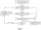
- Fig. 5 shows a flowchart of a method for an MID sub-system accessing a WAN in accordance with an embodiment of the present invention.
- the method for the MID sub-system accessing the WAN in accordance with the embodiment of the present invention comprises the steps as follows.
- Step 501 the MID sub-system receives a connection request for carrying out a data connection with the WAN.
- the MID sub-system receives a connection request for carrying out a data connection with the WAN from a device, connected with the MID sub-system, requesting access to a network.
- the device, connected with the MID sub-system, requesting access to a network is, for example, a mobile terminal with a Bluetooth connection function.
- Step 502 it is judged whether the wireless access of the WAN connected with the MID sub-system has been disabled; if so, execute Step 503; otherwise, execute Step 505.
- the MID sub-system judges whether the wireless access of the WAN connected with the MID sub-system itself has been disabled; if so, execute Step 503; otherwise, execute Step 505, wherein the basis for the MID sub-system judging whether the wireless connection of the WAN connected with the MID sub-system itself has been disabled is: a parameter stored in a memory when a user sets whether to disable the wireless access of the WAN connected with the MID sub-system.
- Step 503 the MID sub-system judges whether the wired connection of the WAN connected with a CPE sub-system has been disabled; if so, execute Step 507; otherwise, execute Sep 504.
- the basis for the MID sub-system judging whether the wired connection of the WAN connected with the CPE sub-system has been disabled is: a parameter stored in a memory when a user sets whether to disable the wired connection of the WAN connected with the CPE sub-system.
- Step 504 the CPE sub-system carries out the wired connection to the WAN; if the connection succeeds, execute Step 506; otherwise, execute Step 502.
- the MID sub-system sends the connection request for carrying out a data connection with the WAN to the CPE sub-system through a connection interface, to notify the CPE sub-system to start carrying out the wired connection to the WAN connected with CPE sub-system.
- the CPE sub-system carries out the wired connection to the WAN connected with the CPE sub-system in a mode of PPPoE; if the connection succeeds, execute Step 506; otherwise, execute Step 502.
- Step 505 the MID sub-system carries out the wireless connection to the WAN; if the connection succeeds, execute Step 506; otherwise, execute Step 503.
- the MID sub-system carries out the wireless connection to the WAN connected with the MID sub-system in a mode of PPP; if the connection succeeds, execute Step 506; otherwise, execute Step 503, so that a wired connection can be carried out with the WAN through the CPE sub-system when the MID sub-system fails to carry out the wireless connection to the WAN connected with the MID sub-system itself in a mode of PPP.
- Step 506 enjoy network services; end the current access process.
- the device connected with the MID sub-system, requesting access to a network starts enjoying network services.
- Step 507 display prompt information which prompts that the WAN is not able to be accessed.
- devices such a display can be adopted to prompt to a user that both the CPE sub-system and MID sub-system are not able to access the WAN and therefore the network connection can not be realized.
Landscapes
- Engineering & Computer Science (AREA)
- Computer Networks & Wireless Communication (AREA)
- Signal Processing (AREA)
- Mobile Radio Communication Systems (AREA)
- Computer And Data Communications (AREA)
- Small-Scale Networks (AREA)
- Selective Calling Equipment (AREA)
Claims (10)
- Ein Zugriffssystem, das Folgendes umfasst: ein Teilnehmernetzgerät(CPE-)-Teilsystem, ein Mobile Internet Vorrichtungs(MID-)-Teilsystem und eine Verbindungsschnittstelle, wobei
die Verbindungsschnittstelle konfiguriert ist, um einen Kanal für die Kommunikation zwischen dem CPE-Teilsystem und dem MID-Teilsystem bereitzustellen;
das CPE-Teilsystem konfiguriert ist, um eine Verbindungsanfrage zu empfangen, um eine Datenverbindung mit einem WAN herzustellen; wenn erkannt wird, dass das CPE-Teilsystem selbst nicht in der Lage ist, eine Kabelverbindung mit dem WAN herzustellen, die Verbindungsanfrage über die Verbindungsschnittstelle an das MID-Teilsystem zu senden, so dass die Datenverbindung zwischen dem CPE-Teilsystem und dem WAN hergestellt wird über eine Funkverbindung zwischen dem MID-Teilsystem und dem WAN und eine Datenübermittlung zwischen dem CPE-Teilsystem und dem MID-Teilsystem; wobei das Erkennen, dass das CPE-Teilsystem selbst nicht in der Lage ist, eine Kabelverbindung mit dem WAN herzustellen, Folgendes umfasst: Ermitteln, ob der Kabelzugang- des WAN, das mit dem CPE-Teilsystem verbunden ist, deaktiviert ist; wobei die Grundlage dafür, dass das CPE-Teilsystem ermittelt, ob der Kabelzugang des WAN, das mit dem CPE-Teilsystem selbst verbunden ist, deaktiviert ist, Folgendes ist: ein in einem Speicher gespeicherter Parameter, wenn ein Nutzer einstellt, ob der Kabelzugang des mit dem CPE-Teilsystem verbundenen WAN deaktiviert werden soll; und
das MID-Teilsystem konfiguriert ist, um eine Verbindungsanfrage zur Herstellung einer Datenverbindung mit dem, WAN zu empfangen; wenn erkannt wird, dass das MID-Teilsystem selbst nicht in der Lage ist, eine Funkverbindung mit dem WAN herzustellen, die Verbindungsanfrage über die Verbindungsschnittstelle an das CPE-Teilsystem zu senden, so dass die Datenverbindung zwischen dem MID-Teilsystem und dem WAN hergestellt wird über eine Kabelverbindung zwischen dem CPE-Teilsystem und dem WAN und eine Datenübermittlung zwischen dem MID-Teilsystem und dem CPE-Teilsystem; wobei das Erkennen, dass das MID-Teilsystem selbst nicht in der Lage ist, eine Funkverbindung mit dem WAN herzustellen, Folgendes umfasst: Ermitteln, ob der Funkzugang des WAN, das mit dem MID-Teilsystem verbunden ist, deaktiviert ist; wobei die Grundlage dafür, dass das MID-Teilsystem ermittelt, ob der Funkzugang des WAN, das mit dem MID-Teilsystem selbst verbunden ist, deaktiviert ist, Folgendes ist: ein in einem Speicher gespeicherter Parameter, wenn ein Nutzer einstellt, ob der Funkzugang des mit dem MID-Teilsystem verbundenen WAN deaktiviert werden soll. - Das System gemäß Anspruch 1, dadurch gekennzeichnet, dass es weiter Folgendes umfasst:eine Ladeschnittstelle, konfiguriert, um eine Ladefunktion für eine Batterie im MID-Teilsystem durch das CPE-Teilsystem zu implementieren.
- Das System gemäß Anspruch 1 oder 2, dadurch gekennzeichnet, dass
das CPE-Teilsystem weiter konfiguriert ist, um eine Kabelverbindung mit dem WAN herzustellen; und
das MID-Teilsystem weiter konfiguriert ist, um eine Funkverbindung mit dem WAN herzustellen. - Ein Zugriffsverfahren, das Folgendes umfasst:durch ein CPE-Teilsystem: Empfangen einer Verbindungsanfrage zur Herstellung einer Datenverbindung mit einem WAN; wenn erkannt wird, dass das CPE-Teilsystem selbst nicht in der Lage ist, eine Kabelverbindung mit dem WAN herzustellen, Senden der Verbindungsanfrage über eine Verbindungsschnittstelle an ein MID-Teilsystem, so dass die Datenverbindung zwischen dem CPE-Teilsystem und dem WAN hergestellt wird über eine Funkverbindung zwischen dem MID-Teilsystem und dem WAN und eine Datenübermittlung zwischen dem CPE-Teilsystem und dem MID-Teilsystem;durch das MID-Teilsystem: Empfangen einer Verbindungsanfrage zur Herstellung einer Datenverbindung mit dem WAN; wenn erkannt wird, dass das MID-Teilsystem selbst nicht in der Lage ist, eine Funkverbindung mit dem WAN herzustellen, Senden der Verbindungsanfrage über die Verbindungsschnittstelle an das CPE-Teilsystem, so dass die Datenverbindung zwischen dem MID-Teilsystem und dem WAN hergestellt wird über eine Kabelverbindung zwischen dem CPE-Teilsystem und dem WAN und eine Datenübermittlung zwischen dem MID-Teilsystem und dem CPE-Teilsystem; wobei das Erkennen, dass das CPE-Teilsystem selbst nicht in der Lage ist, eine Kabelverbindung mit dem WAN herzustellen, Folgendes umfasst: Ermitteln, ob der Kabelzugang des WAN, das mit dem CPE-Teilsystem verbunden ist, deaktiviert ist; wobei die Grundlage dafür, dass das CPE-Teilsystem ermittelt, ob der Kabelzugang des WAN, das mit dem CPE-Teilsystem selbst verbunden ist, deaktiviert ist, Folgendes ist: ein in einem Speicher gespeicherter Parameter, wenn ein Nutzer einstellt, ob der Kabelzugang des mit dem CPE-Teilsystem verbundenen WAN deaktiviert werden soll;wobei das Erkennen, dass das MID-Teilsystem selbst nicht in der Lage ist, eine Funkverbindung mit dem WAN herzustellen, Folgendes umfasst: Ermitteln, ob der Funkzugang des WAN, das mit dem MID-Teilsystem verbunden ist, deaktiviert ist; wobei die Grundlage dafür, dass das MID-Teilsystem ermittelt, ob der Funkzugang des WAN, das mit dem MID-Teilsystem selbst verbunden ist, deaktiviert ist, Folgendes ist: ein in einem Speicher gespeicherter Parameter, wenn ein Nutzer einstellt, ob der Funkzugang des mit dem MID-Teilsystem verbundenen WAN deaktiviert werden soll.
- Das Verfahren gemäß Anspruch 4, dadurch gekennzeichnet, dass es weiter Folgendes umfasst:Herstellen einer Kabelverbindung mit dem WAN über das CPE-Teilsystem, wenn das CPE-Teilsystem in der Lage ist, die Kabelverbindung mit dem WAN herzustellen; undHerstellen einer Funkverbindung mit dem WAN über das MID-Teilsystem, wenn das MID-Teilsystem in der Lage ist, die Funkverbindung mit dem WAN herzustellen.
- Das Verfahren gemäß Anspruch 5, dadurch gekennzeichnet, dass
der Schritt, dass das CPE-Teilsystem die Kabelverbindung mit dem WAN herstellt, Folgendes umfasst: das Herstellen, durch das CPE-Teilsystem, der Kabelverbindung mit dem WAN, das mit dem CPE-Teilsystem verbunden ist, durch einen Point to Point Protocol Over Ethernet-(PPPoE-)Modus;
der Schritt, dass das MID-Teilsystem die Funkverbindung mit dem WAN herstellt, Folgendes umfasst: das Herstellen, durch das MID-Teilsystem, der Funkverbindung mit dem WAN, das mit dem MID-Teilsystem verbunden ist, durch einen Point to Point Protocol-(PPP-)Modus. - Das Verfahren gemäß einem beliebigen der Ansprüche 4-6, dadurch gekennzeichnet, dass es weiter Folgendes umfasst: wenn das CPE-Teilsystem nicht in der Lage ist, die Kabelverbindung mit dem WAN herzustellen, und das MID-Teilsystem nicht in der Lage ist, die Funkverbindung mit dem WAN herzustellen, Melden, dass auf das WAN nicht zugegriffen werden kann.
- Eine CPE-Vorrichtung, die Folgendes umfasst:ein PPPoE-Zugriffsmodul, konfiguriert, um über einen WAN-Anschluss durch ein CPE-Teilsystem einen festen Breitbandzugriff in einem Kabelverbindungsmodus auf ein WAN durchzuführen;ein WAN-Zugriffsmodus-Auswahlmodul, konfiguriert, um eine Verbindungsanfrage zur Herstellung einer Datenverbindung mit dem WAN zu empfangen und, bei Erkennung, dass das CPE-Teilsystem nicht in der Lage ist, eine Kabelverbindung mit dem WAN herzustellen, die Verbindungsanfrage über eine Wireless Fidelity-(WiFi-)Schnittstelle an ein Wireless Fidelity Access Point-(WiFi AP-)Modul zu senden;das WiFi AP-Modul, konfiguriert, um drahtlose Versorgung zu bieten, die in einem WiFi-Modus durchgeführt wird, um es einem MID-Teilsystem mit Wireless Fidelity Client-(WiFi Client-)Modul zu ermöglichen, auf das CPE-Teilsystem zuzugreifen, und die Verbindungsanfrage über die WiFi-Schnittstelle an das MID-Teilsystem zu senden, so dass die Datenverbindung zwischen dem CPE-Teilsystem und dem WAN durch eine Funkverbindung zwischen dem MID-Teilsystem und dem WAN und eine Datenübermittlung zwischen dem CPE-Teilsystem und dem MID-Teilsystem hergestellt wird,wobei das WiFi AP-Modul weiter konfiguriert ist, um das PPPoE-Zugriffsmodul auszulösen, nachdem es vom MID-Teilsystem eine Verbindungsanfrage zur Herstellung einer Datenverbindung mit dem WAN erhalten hat;wobei das Ermitteln, dass das CPE-Teilsystem nicht in der Lage ist, eine Kabelverbindung mit dem WAN herzustellen, Folgendes umfasst: Feststellen, ob der Kabelzugang des mit dem CPE-Teilsystem verbundenen WAN deaktiviert wurde; wobei die Grundlage dafür, dass das CPE-Teilsystem ermittelt, ob der Funkzugang des WAN, das mit dem CPE-Teilsystem selbst verbunden ist, deaktiviert wurde, Folgendes ist: ein in einem Speicher gespeicherter Parameter, wenn ein Nutzer einstellt, ob der Kabelzugang des mit dem CPE-Teilsystem verbundenen WAN deaktiviert werden soll.
- Eine MID-Vorrichtung, die Folgendes umfasst:ein PPP-Zugriffsmodul, konfiguriert, um mit einer Mobilfunk-Datenkarte über ein MID-Teilsystem einen Funkzugriff auf ein WAN durchzuführen;ein WAN-Zugriffsmodus-Auswahlmodul, konfiguriert, um eine Verbindungsanfrage zur Herstellung einer Datenverbindung mit dem WAN zu empfangen und, bei Feststellung, dass das MID-Teilsystem nicht in der Lage ist, die Funkverbindung mit dem WAN herzustellen, die Verbindungsanfrage über eine WiFi-Schnittstelle an ein WiFi-Client-Modul zu senden; unddas WiFi Client-Modul, konfiguriert, um eine Funkkommunikation mit einem WiFi AP-Modul in einem CPE-Teilsystem herzustellen, indem das MID-Teilsystem als WiFi Client genommen wird, und die Verbindungsanfrage über die WiFi-Schnittstelle an das CPE-Teilsystem zu senden, so dass die Datenverbindung zwischen dem MID-Teilsystem und dem WAN durch eine Kabelverbindung zwischen dem CPE-Teilsystem und dem WAN und eine Datenübermittlung zwischen dem MID-Teilsystem und dem CPE-Teilsystem hergestellt wird;wobei das Feststellen, dass das MID-Teilsystem nicht in der Lage ist, eine Funkverbindung mit dem WAN herzustellen, Folgendes umfasst: Ermitteln, ob der Funkzugang des mit dem MID-Teilsystem verbundenen WAN deaktiviert wurde, wobei die Grundlage dafür, dass das MID-Teilsystem ermittelt, ob der Funkzugang des WAN, das mit dem MID-Teilsystem selbst verbunden ist, deaktiviert wurde, Folgendes ist: ein in einem Speicher gespeicherter Parameter, wenn ein Nutzer einstellt, ob der Funkzugang des mit dem MID-Teilsystem verbundenen WAN deaktiviert werden soll.
- Die Vorrichtung gemäß Anspruch 9, dadurch gekennzeichnet, dass
das WiFi Client-Modul weiter konfiguriert ist, um das PPP-Zugriffsmodul auszulösen, nachdem es vom CPE-Teilsystem eine Verbindungsanfrage zur Herstellung einer Datenverbindung mit dem WAN empfangen hat.
Applications Claiming Priority (2)
| Application Number | Priority Date | Filing Date | Title |
|---|---|---|---|
| CN201010000922A CN101754434A (zh) | 2010-01-20 | 2010-01-20 | 一种接入方法、系统及装置 |
| PCT/CN2010/071234 WO2010148677A1 (zh) | 2010-01-20 | 2010-03-23 | 一种接入方法、系统及装置 |
Publications (3)
| Publication Number | Publication Date |
|---|---|
| EP2528285A1 EP2528285A1 (de) | 2012-11-28 |
| EP2528285A4 EP2528285A4 (de) | 2013-11-20 |
| EP2528285B1 true EP2528285B1 (de) | 2017-09-20 |
Family
ID=42480615
Family Applications (1)
| Application Number | Title | Priority Date | Filing Date |
|---|---|---|---|
| EP10791183.6A Active EP2528285B1 (de) | 2010-01-20 | 2010-03-23 | Zugangsverfahren, system und vorrichtung |
Country Status (4)
| Country | Link |
|---|---|
| US (1) | US8929289B2 (de) |
| EP (1) | EP2528285B1 (de) |
| CN (1) | CN101754434A (de) |
| WO (1) | WO2010148677A1 (de) |
Families Citing this family (6)
| Publication number | Priority date | Publication date | Assignee | Title |
|---|---|---|---|---|
| CN102957561B (zh) * | 2011-08-31 | 2017-10-10 | 中兴通讯股份有限公司 | 一种支持多上行用户设备入网时自动识别的方法及装置 |
| CN102638847B (zh) * | 2012-04-11 | 2014-06-18 | 苏州英菲泰尔电子科技有限公司 | 蜂窝式自生长无线通信系统 |
| US10972339B2 (en) | 2018-08-22 | 2021-04-06 | Verizon Patent And Licensing Inc. | Systems and methods for modular in-premises equipment |
| CN110708731B (zh) * | 2019-09-18 | 2022-01-28 | 江门职业技术学院 | 一种无线网桥控制方法和系统 |
| CN113453250B (zh) * | 2021-05-25 | 2023-12-26 | 新华三技术有限公司成都分公司 | 一种云ap的配置方法和云管理平台 |
| CN113810945B (zh) * | 2021-09-22 | 2023-06-20 | 广州通则康威智能科技有限公司 | 多路上行负载均衡方法、装置、计算机设备及存储介质 |
Family Cites Families (13)
| Publication number | Priority date | Publication date | Assignee | Title |
|---|---|---|---|---|
| EP0986285A2 (de) * | 1998-09-10 | 2000-03-15 | Alcatel | System und Verfahren zur Durchführung einer Sicherungsleitung in einem Telekommunikationsnetzwerk |
| CN100337461C (zh) * | 2000-03-17 | 2007-09-12 | 美国在线服务公司 | 家庭联网的系统和方法 |
| TWI220608B (en) * | 2001-02-21 | 2004-08-21 | Admtek Inc | Gateway device operating between local area network and wide area network |
| US20040001496A1 (en) * | 2002-06-21 | 2004-01-01 | Jon Yusko | Method and apparatus for PPP auto-connect |
| AU2003242944A1 (en) * | 2002-07-10 | 2004-02-02 | Koninklijke Philips Electronics N.V. | Interface selection from multiple networks |
| US7305511B2 (en) | 2002-12-23 | 2007-12-04 | Microtune (Texas), L.P. | Providing both wireline and wireless connections to a wireline interface |
| US7995516B2 (en) * | 2003-01-28 | 2011-08-09 | Top Global Technologies Limited | Mobile wireless base station |
| CN1172489C (zh) | 2003-01-28 | 2004-10-20 | 北京朗通环球科技有限公司 | 基于网络之间的数据通信系统及方法 |
| JP2005051473A (ja) * | 2003-07-28 | 2005-02-24 | Sony Corp | ネットワーク相互接続装置及びネットワーク相互接続方法、名前解決装置、並びにコンピュータ・プログラム |
| US7142852B2 (en) * | 2003-11-13 | 2006-11-28 | Motorola, Inc. | Method and gateway for controlling call routing |
| EP1800450B1 (de) * | 2004-10-15 | 2010-08-04 | Pirelli & C. S.p.A. | Verfahren zur sicheren signalübertragung in einem telekommunikationsnetz insbesondere in einem lokalen netzwerk |
| CN100418322C (zh) * | 2006-01-23 | 2008-09-10 | 北京朗通环球科技有限公司 | 一种对计算机网络的链路备份方法及装置 |
| EP1962453A1 (de) | 2007-02-26 | 2008-08-27 | Siemens Networks GmbH & Co. KG | Verfahren zur Aktivierung der Netzwerkknotenredundanz in einem Zugangsnetz, Nachrichten und Knoten |
-
2010
- 2010-01-20 CN CN201010000922A patent/CN101754434A/zh active Pending
- 2010-03-23 WO PCT/CN2010/071234 patent/WO2010148677A1/zh not_active Ceased
- 2010-03-23 US US13/574,014 patent/US8929289B2/en active Active
- 2010-03-23 EP EP10791183.6A patent/EP2528285B1/de active Active
Non-Patent Citations (1)
| Title |
|---|
| None * |
Also Published As
| Publication number | Publication date |
|---|---|
| EP2528285A1 (de) | 2012-11-28 |
| CN101754434A (zh) | 2010-06-23 |
| WO2010148677A1 (zh) | 2010-12-29 |
| US20120287864A1 (en) | 2012-11-15 |
| US8929289B2 (en) | 2015-01-06 |
| EP2528285A4 (de) | 2013-11-20 |
Similar Documents
| Publication | Publication Date | Title |
|---|---|---|
| US8929289B2 (en) | Access method, system and device | |
| EP2671407B1 (de) | System und verfahren für host- und betriebssystem-unbewusste verwaltung verbundener vorrichtungen durch netzwerkgesteuerte zustandsänderung | |
| US8261341B2 (en) | UPnP VPN gateway configuration service | |
| EP2725868B1 (de) | System und Verfahren zur Steuerung des Verbindungs-Timeouts in einem Kommunikationsnetzwerk | |
| EP2542021B1 (de) | Verfahren und vorrichtung für kommunikationen über ein doppelnetzwerkendgerät | |
| CN105517069B (zh) | 一种通信模式切换方法以及移动终端 | |
| US10305959B2 (en) | Self-organizing network communication | |
| CN113225208A (zh) | 基于条件重新启动网络装置的一个或多个组件的方法和系统 | |
| CN103024462B (zh) | 一种网络检测的方法及数字终端 | |
| WO2011140091A1 (en) | Multi-client local network base station | |
| KR20100031309A (ko) | 통신 네트워크의 디바이스 관리 방법 및 시스템 | |
| EP2725755A1 (de) | Datenkarte und aktivierungsverfahren dafür | |
| CN105491568A (zh) | 一种自动接入路由的方法、装置及智能终端 | |
| CN102833605A (zh) | 带路由功能的网络电视机系统 | |
| CN108391298A (zh) | 一种网络自动切换的系统及电子设备 | |
| CN103561435A (zh) | 多模终端和通信方法 | |
| CN104469970B (zh) | 一种重连接数据网络的方法和装置 | |
| EP3145181A1 (de) | Digitalempfängernetzwerkschaltverfahren, vorrichtung und digitalempfänger damit | |
| EP2840855A1 (de) | Netzanschlussverfahren und system | |
| CN101466130B (zh) | 网络连接的控制方法和装置 | |
| EP2645623B1 (de) | Verfahren, vorrichtung und system zur verwaltung von drahtlosen endgeräten über einen remote-server | |
| US20150229554A1 (en) | Mobile Terminal Network Port Management Method and Device | |
| CN105307184A (zh) | 一种管理移动热点的方法、装置及系统 | |
| US20140334288A1 (en) | Wireless tap-off device capable of providing wireless lan service | |
| CN107465586A (zh) | 路由器 |
Legal Events
| Date | Code | Title | Description |
|---|---|---|---|
| PUAI | Public reference made under article 153(3) epc to a published international application that has entered the european phase |
Free format text: ORIGINAL CODE: 0009012 |
|
| 17P | Request for examination filed |
Effective date: 20120726 |
|
| AK | Designated contracting states |
Kind code of ref document: A1 Designated state(s): AT BE BG CH CY CZ DE DK EE ES FI FR GB GR HR HU IE IS IT LI LT LU LV MC MK MT NL NO PL PT RO SE SI SK SM TR |
|
| DAX | Request for extension of the european patent (deleted) | ||
| A4 | Supplementary search report drawn up and despatched |
Effective date: 20131022 |
|
| RIC1 | Information provided on ipc code assigned before grant |
Ipc: H04L 12/46 20060101AFI20131016BHEP |
|
| 17Q | First examination report despatched |
Effective date: 20141016 |
|
| GRAP | Despatch of communication of intention to grant a patent |
Free format text: ORIGINAL CODE: EPIDOSNIGR1 |
|
| INTG | Intention to grant announced |
Effective date: 20170405 |
|
| GRAS | Grant fee paid |
Free format text: ORIGINAL CODE: EPIDOSNIGR3 |
|
| GRAA | (expected) grant |
Free format text: ORIGINAL CODE: 0009210 |
|
| AK | Designated contracting states |
Kind code of ref document: B1 Designated state(s): AT BE BG CH CY CZ DE DK EE ES FI FR GB GR HR HU IE IS IT LI LT LU LV MC MK MT NL NO PL PT RO SE SI SK SM TR |
|
| REG | Reference to a national code |
Ref country code: GB Ref legal event code: FG4D |
|
| REG | Reference to a national code |
Ref country code: CH Ref legal event code: EP |
|
| REG | Reference to a national code |
Ref country code: AT Ref legal event code: REF Ref document number: 930910 Country of ref document: AT Kind code of ref document: T Effective date: 20171015 |
|
| REG | Reference to a national code |
Ref country code: IE Ref legal event code: FG4D |
|
| REG | Reference to a national code |
Ref country code: DE Ref legal event code: R096 Ref document number: 602010045419 Country of ref document: DE |
|
| REG | Reference to a national code |
Ref country code: NL Ref legal event code: MP Effective date: 20170920 |
|
| PG25 | Lapsed in a contracting state [announced via postgrant information from national office to epo] |
Ref country code: LT Free format text: LAPSE BECAUSE OF FAILURE TO SUBMIT A TRANSLATION OF THE DESCRIPTION OR TO PAY THE FEE WITHIN THE PRESCRIBED TIME-LIMIT Effective date: 20170920 Ref country code: NO Free format text: LAPSE BECAUSE OF FAILURE TO SUBMIT A TRANSLATION OF THE DESCRIPTION OR TO PAY THE FEE WITHIN THE PRESCRIBED TIME-LIMIT Effective date: 20171220 Ref country code: SE Free format text: LAPSE BECAUSE OF FAILURE TO SUBMIT A TRANSLATION OF THE DESCRIPTION OR TO PAY THE FEE WITHIN THE PRESCRIBED TIME-LIMIT Effective date: 20170920 Ref country code: HR Free format text: LAPSE BECAUSE OF FAILURE TO SUBMIT A TRANSLATION OF THE DESCRIPTION OR TO PAY THE FEE WITHIN THE PRESCRIBED TIME-LIMIT Effective date: 20170920 Ref country code: FI Free format text: LAPSE BECAUSE OF FAILURE TO SUBMIT A TRANSLATION OF THE DESCRIPTION OR TO PAY THE FEE WITHIN THE PRESCRIBED TIME-LIMIT Effective date: 20170920 |
|
| REG | Reference to a national code |
Ref country code: LT Ref legal event code: MG4D |
|
| REG | Reference to a national code |
Ref country code: AT Ref legal event code: MK05 Ref document number: 930910 Country of ref document: AT Kind code of ref document: T Effective date: 20170920 |
|
| PG25 | Lapsed in a contracting state [announced via postgrant information from national office to epo] |
Ref country code: BG Free format text: LAPSE BECAUSE OF FAILURE TO SUBMIT A TRANSLATION OF THE DESCRIPTION OR TO PAY THE FEE WITHIN THE PRESCRIBED TIME-LIMIT Effective date: 20171220 Ref country code: GR Free format text: LAPSE BECAUSE OF FAILURE TO SUBMIT A TRANSLATION OF THE DESCRIPTION OR TO PAY THE FEE WITHIN THE PRESCRIBED TIME-LIMIT Effective date: 20171221 Ref country code: LV Free format text: LAPSE BECAUSE OF FAILURE TO SUBMIT A TRANSLATION OF THE DESCRIPTION OR TO PAY THE FEE WITHIN THE PRESCRIBED TIME-LIMIT Effective date: 20170920 |
|
| REG | Reference to a national code |
Ref country code: FR Ref legal event code: PLFP Year of fee payment: 9 |
|
| PG25 | Lapsed in a contracting state [announced via postgrant information from national office to epo] |
Ref country code: NL Free format text: LAPSE BECAUSE OF FAILURE TO SUBMIT A TRANSLATION OF THE DESCRIPTION OR TO PAY THE FEE WITHIN THE PRESCRIBED TIME-LIMIT Effective date: 20170920 |
|
| REG | Reference to a national code |
Ref country code: DE Ref legal event code: R082 Ref document number: 602010045419 Country of ref document: DE Representative=s name: SCHIEBER - FARAGO PATENTANWAELTE, DE Ref country code: DE Ref legal event code: R082 Ref document number: 602010045419 Country of ref document: DE Representative=s name: FARAGO PATENTANWALTSGESELLSCHAFT MBH, DE Ref country code: DE Ref legal event code: R082 Ref document number: 602010045419 Country of ref document: DE Representative=s name: FARAGO PATENTANWALTS- UND RECHTSANWALTSGESELLS, DE Ref country code: DE Ref legal event code: R082 Ref document number: 602010045419 Country of ref document: DE Representative=s name: FARAGO PATENTANWAELTE, DE |
|
| PG25 | Lapsed in a contracting state [announced via postgrant information from national office to epo] |
Ref country code: CZ Free format text: LAPSE BECAUSE OF FAILURE TO SUBMIT A TRANSLATION OF THE DESCRIPTION OR TO PAY THE FEE WITHIN THE PRESCRIBED TIME-LIMIT Effective date: 20170920 Ref country code: RO Free format text: LAPSE BECAUSE OF FAILURE TO SUBMIT A TRANSLATION OF THE DESCRIPTION OR TO PAY THE FEE WITHIN THE PRESCRIBED TIME-LIMIT Effective date: 20170920 Ref country code: PL Free format text: LAPSE BECAUSE OF FAILURE TO SUBMIT A TRANSLATION OF THE DESCRIPTION OR TO PAY THE FEE WITHIN THE PRESCRIBED TIME-LIMIT Effective date: 20170920 |
|
| PG25 | Lapsed in a contracting state [announced via postgrant information from national office to epo] |
Ref country code: SM Free format text: LAPSE BECAUSE OF FAILURE TO SUBMIT A TRANSLATION OF THE DESCRIPTION OR TO PAY THE FEE WITHIN THE PRESCRIBED TIME-LIMIT Effective date: 20170920 Ref country code: IT Free format text: LAPSE BECAUSE OF FAILURE TO SUBMIT A TRANSLATION OF THE DESCRIPTION OR TO PAY THE FEE WITHIN THE PRESCRIBED TIME-LIMIT Effective date: 20170920 Ref country code: AT Free format text: LAPSE BECAUSE OF FAILURE TO SUBMIT A TRANSLATION OF THE DESCRIPTION OR TO PAY THE FEE WITHIN THE PRESCRIBED TIME-LIMIT Effective date: 20170920 Ref country code: EE Free format text: LAPSE BECAUSE OF FAILURE TO SUBMIT A TRANSLATION OF THE DESCRIPTION OR TO PAY THE FEE WITHIN THE PRESCRIBED TIME-LIMIT Effective date: 20170920 Ref country code: IS Free format text: LAPSE BECAUSE OF FAILURE TO SUBMIT A TRANSLATION OF THE DESCRIPTION OR TO PAY THE FEE WITHIN THE PRESCRIBED TIME-LIMIT Effective date: 20180120 Ref country code: SK Free format text: LAPSE BECAUSE OF FAILURE TO SUBMIT A TRANSLATION OF THE DESCRIPTION OR TO PAY THE FEE WITHIN THE PRESCRIBED TIME-LIMIT Effective date: 20170920 |
|
| REG | Reference to a national code |
Ref country code: DE Ref legal event code: R097 Ref document number: 602010045419 Country of ref document: DE |
|
| PLBE | No opposition filed within time limit |
Free format text: ORIGINAL CODE: 0009261 |
|
| STAA | Information on the status of an ep patent application or granted ep patent |
Free format text: STATUS: NO OPPOSITION FILED WITHIN TIME LIMIT |
|
| PG25 | Lapsed in a contracting state [announced via postgrant information from national office to epo] |
Ref country code: DK Free format text: LAPSE BECAUSE OF FAILURE TO SUBMIT A TRANSLATION OF THE DESCRIPTION OR TO PAY THE FEE WITHIN THE PRESCRIBED TIME-LIMIT Effective date: 20170920 |
|
| 26N | No opposition filed |
Effective date: 20180621 |
|
| REG | Reference to a national code |
Ref country code: CH Ref legal event code: PL |
|
| PG25 | Lapsed in a contracting state [announced via postgrant information from national office to epo] |
Ref country code: MC Free format text: LAPSE BECAUSE OF FAILURE TO SUBMIT A TRANSLATION OF THE DESCRIPTION OR TO PAY THE FEE WITHIN THE PRESCRIBED TIME-LIMIT Effective date: 20170920 Ref country code: SI Free format text: LAPSE BECAUSE OF FAILURE TO SUBMIT A TRANSLATION OF THE DESCRIPTION OR TO PAY THE FEE WITHIN THE PRESCRIBED TIME-LIMIT Effective date: 20170920 |
|
| REG | Reference to a national code |
Ref country code: BE Ref legal event code: MM Effective date: 20180331 |
|
| REG | Reference to a national code |
Ref country code: IE Ref legal event code: MM4A |
|
| PG25 | Lapsed in a contracting state [announced via postgrant information from national office to epo] |
Ref country code: LU Free format text: LAPSE BECAUSE OF NON-PAYMENT OF DUE FEES Effective date: 20180323 |
|
| PG25 | Lapsed in a contracting state [announced via postgrant information from national office to epo] |
Ref country code: IE Free format text: LAPSE BECAUSE OF NON-PAYMENT OF DUE FEES Effective date: 20180323 |
|
| PG25 | Lapsed in a contracting state [announced via postgrant information from national office to epo] |
Ref country code: LI Free format text: LAPSE BECAUSE OF NON-PAYMENT OF DUE FEES Effective date: 20180331 Ref country code: CH Free format text: LAPSE BECAUSE OF NON-PAYMENT OF DUE FEES Effective date: 20180331 Ref country code: BE Free format text: LAPSE BECAUSE OF NON-PAYMENT OF DUE FEES Effective date: 20180331 |
|
| PG25 | Lapsed in a contracting state [announced via postgrant information from national office to epo] |
Ref country code: ES Free format text: LAPSE BECAUSE OF FAILURE TO SUBMIT A TRANSLATION OF THE DESCRIPTION OR TO PAY THE FEE WITHIN THE PRESCRIBED TIME-LIMIT Effective date: 20170920 |
|
| PG25 | Lapsed in a contracting state [announced via postgrant information from national office to epo] |
Ref country code: MT Free format text: LAPSE BECAUSE OF NON-PAYMENT OF DUE FEES Effective date: 20180323 |
|
| PG25 | Lapsed in a contracting state [announced via postgrant information from national office to epo] |
Ref country code: TR Free format text: LAPSE BECAUSE OF FAILURE TO SUBMIT A TRANSLATION OF THE DESCRIPTION OR TO PAY THE FEE WITHIN THE PRESCRIBED TIME-LIMIT Effective date: 20170920 |
|
| PG25 | Lapsed in a contracting state [announced via postgrant information from national office to epo] |
Ref country code: HU Free format text: LAPSE BECAUSE OF FAILURE TO SUBMIT A TRANSLATION OF THE DESCRIPTION OR TO PAY THE FEE WITHIN THE PRESCRIBED TIME-LIMIT; INVALID AB INITIO Effective date: 20100323 Ref country code: PT Free format text: LAPSE BECAUSE OF FAILURE TO SUBMIT A TRANSLATION OF THE DESCRIPTION OR TO PAY THE FEE WITHIN THE PRESCRIBED TIME-LIMIT Effective date: 20170920 |
|
| PG25 | Lapsed in a contracting state [announced via postgrant information from national office to epo] |
Ref country code: MK Free format text: LAPSE BECAUSE OF NON-PAYMENT OF DUE FEES Effective date: 20170920 Ref country code: CY Free format text: LAPSE BECAUSE OF FAILURE TO SUBMIT A TRANSLATION OF THE DESCRIPTION OR TO PAY THE FEE WITHIN THE PRESCRIBED TIME-LIMIT Effective date: 20170920 |
|
| REG | Reference to a national code |
Ref country code: DE Ref legal event code: R082 Ref document number: 602010045419 Country of ref document: DE Representative=s name: SCHIEBER - FARAGO PATENTANWAELTE, DE Ref country code: DE Ref legal event code: R082 Ref document number: 602010045419 Country of ref document: DE Representative=s name: FARAGO PATENTANWALTSGESELLSCHAFT MBH, DE |
|
| REG | Reference to a national code |
Ref country code: DE Ref legal event code: R082 Ref document number: 602010045419 Country of ref document: DE Representative=s name: SCHIEBER - FARAGO PATENTANWAELTE, DE |
|
| PGFP | Annual fee paid to national office [announced via postgrant information from national office to epo] |
Ref country code: DE Payment date: 20241231 Year of fee payment: 16 |
|
| PGFP | Annual fee paid to national office [announced via postgrant information from national office to epo] |
Ref country code: FR Payment date: 20250210 Year of fee payment: 16 |
|
| PGFP | Annual fee paid to national office [announced via postgrant information from national office to epo] |
Ref country code: GB Payment date: 20250102 Year of fee payment: 16 |