EP2528249B1 - Method and system for data transmission - Google Patents
Method and system for data transmission Download PDFInfo
- Publication number
- EP2528249B1 EP2528249B1 EP10845589.0A EP10845589A EP2528249B1 EP 2528249 B1 EP2528249 B1 EP 2528249B1 EP 10845589 A EP10845589 A EP 10845589A EP 2528249 B1 EP2528249 B1 EP 2528249B1
- Authority
- EP
- European Patent Office
- Prior art keywords
- rnti
- user equipment
- data
- relay node
- mapping relationship
- Prior art date
- Legal status (The legal status is an assumption and is not a legal conclusion. Google has not performed a legal analysis and makes no representation as to the accuracy of the status listed.)
- Active
Links
Images


Classifications
-
- H—ELECTRICITY
- H04—ELECTRIC COMMUNICATION TECHNIQUE
- H04W—WIRELESS COMMUNICATION NETWORKS
- H04W72/00—Local resource management
- H04W72/20—Control channels or signalling for resource management
-
- H—ELECTRICITY
- H04—ELECTRIC COMMUNICATION TECHNIQUE
- H04W—WIRELESS COMMUNICATION NETWORKS
- H04W48/00—Access restriction; Network selection; Access point selection
- H04W48/08—Access restriction or access information delivery, e.g. discovery data delivery
-
- H—ELECTRICITY
- H04—ELECTRIC COMMUNICATION TECHNIQUE
- H04W—WIRELESS COMMUNICATION NETWORKS
- H04W8/00—Network data management
- H04W8/26—Network addressing or numbering for mobility support
-
- H—ELECTRICITY
- H04—ELECTRIC COMMUNICATION TECHNIQUE
- H04W—WIRELESS COMMUNICATION NETWORKS
- H04W84/00—Network topologies
- H04W84/02—Hierarchically pre-organised networks, e.g. paging networks, cellular networks, WLAN [Wireless Local Area Network] or WLL [Wireless Local Loop]
- H04W84/04—Large scale networks; Deep hierarchical networks
- H04W84/042—Public Land Mobile systems, e.g. cellular systems
- H04W84/047—Public Land Mobile systems, e.g. cellular systems using dedicated repeater stations
Definitions
- Embodiments of the present invention relate to the field of data transmission technologies, and in particular, to a method and system for data transmission.
- HSDPA High Speed Downlink Packet Access
- 3GPP Third Generation Partnership Project
- HSDPA High Speed Downlink Packet Access
- 3GPP Third Generation Partnership Project
- HSDPA High Speed Downlink Packet Access
- TTI Transmission Time Interval
- the transmission mode of a 2-ms TTI that is generally used in the existing HSDPA technology improves the data transmission rate, but the transmission mode of the 2-ms TTI belongs to short frame transmission, reducing the downlink coverage capability of a cell edge. Consequently, the efficiency in transmitting data to a user equipment at the cell edge is reduced.
- US 2008/0188220 A1 discloses a method and an apparatus for a cell update. After selecting a target cell, system information is read from the target cell including high speed downlink shared channel (HS-DSCH) common system information. A radio network temporary identity (RNTI) received in a source cell is cleared. An HS-DSCH medium access control entity is configured based on the HS-DSCH common system information. High speed downlink packet access transmission is then received in the target cell.
- HS-DSCH high speed downlink shared channel
- RNTI radio network temporary identity
- the present invention is directed to a method and system for data transmission, capable of effectively improving the efficiency in transmitting data to a user equipment at a cell edge.
- the present invention provides a method for data transmission, applied in an HSDPA network, where the method includes:
- the present invention provides a radio network control device, where the device includes:
- the present invention provides an access device, where the device includes:
- the present invention provides a system for data transmission, where the system includes: a relay node, an access device and a radio network control device.
- the radio network control device is configured to obtain a prestored mapping relationship between a first H-RNTI of a user equipment and a second H-RNTI of a relay node accessed by the user equipment; and send, according to the mapping relationship, the first H-RNTI, the second H-RNTI and data to the access device.
- the access device is configured to receive the first H-RNTI, the second H-RNTI and the data that are sent by the radio network control device; and send, according to the second H-RNTI, the first H-RNTI and the data to the relay node.
- the relay node is configured to receive the first H-RNTI and the data that are sent by the access device; and send the data to the user equipment corresponding to the first H-RNTI.
- the method and system for data transmission described above enhance the downlink coverage capability of a cell edge and further improve the efficiency in transmitting data to a user equipment at the cell edge.
- UE User Equipment
- HS-DSCH High-Speed Downlink Shared Channel
- a control radio network controller (Control Radio Network Controller, hereinafter referred to as CRNC) configures an HS-DSCH radio network temporary identity (HS-DSCH Radio Network Temporary Identity, hereinafter referred to as H-RNTI) respectively for different UEs to identify different UEs.
- H-RNTI HS-DSCH Radio Network Temporary Identity
- HS-SCCH High-Speed Shared Control Channel
- HS-PDSCH High-Speed Physical Downlink Shared Channel
- a radio access network in the HSDPA network of the embodiments of the present invention includes a radio network controller (Radio Network Controller, hereinafter referred to as RNC) and a Node B, where data is transmitted between the RNC and the Node B according to the Frame Protocol (FP).
- RNC Radio Network Controller
- FP Frame Protocol
- An embodiment of the present invention provides a method for data transmission.
- the method for data transmission is applied in an HSDPA network, and includes: sending, according to a mapping relationship between a first H-RNTI of a user equipment and a second H-RNTI of a relay node accessed by the user equipment, data to the user equipment corresponding to the first H-RNTI by using the relay node corresponding to the second H-RNTI.
- RN relay Node
- data to be sent to a UE may be sent, according to a mapping relationship between a first H-RNTI of the UE and a second H-RNTI of an RN accessed by the UE, to the UE accurately by using the RN .
- the method for data transmission according to this embodiment can enhance the downlink coverage capability of a cell edge and further improve the efficiency in transmitting data to a user equipment at the cell edge.
- FIG. 1 is a flowchart of a method for data transmission according to an embodiment of the present invention. As shown in FIG. 1 , the method for data transmission according to this embodiment may be as follows.
- a radio network control device obtains a prestored mapping relationship between the first H-RNTI of the user equipment and the second H-RNTI of the relay node accessed by the user equipment.
- the radio network control device sends, according to the mapping relationship, the first H-RNTI, the second H-RNTI and the data to an access device so that the access device sends the data to the user equipment corresponding to the first H-RNTI by using the relay node corresponding to the second H-RNTI.
- an RNC manages and maintains a mapping relationship between a first H-RNTI of a UE and a second H-RNTI of an RN accessed by the UE.
- the RNC obtains the mapping relationship, prestored in the RNC, between the first H-RNTI of the UE and the second H-RNTI of the RN accessed by the UE, and then sends the first H-RNTI, the second H-RNTI and data, for example, sends an FP data packet including the first H-RNTI, the second H-RNTI and data, to an access device (for example, a Node B or a gateway; a Node B is used as an example of the access device below) through an Iub interface according to the mapping relationship.
- the HSDPA FP data packet sent by the RNC to the Node B is specifically in the form shown in Table 1.
- the FP header of the data packet carries the second H-RNTI of the RN accessed by the UE that is configured to receive data
- the DATA part includes the first H-RNTI assigned to the UE and the data to be sent to the UE.
- the Node B parses the FP data packet to obtain the second H-RNTI carried in the FP header, and then sends the first H-RNTI and the data to the RN corresponding to the second H-RNTI accurately.
- the Node B When sending the data to the RN, the Node B adds the second H-RNTI of the RN on an HS-SCCH of an air interface so that after the corresponding RN detects that this second H-RNTI is consistent with the second H-RNTI configured for the RN, the RN receives the first H-RNTI and the data that are sent by the Node B to the RN.
- the RN After receiving the first H-RNTI and the data, the RN performs parsing to obtain the first H-RNTI, sends the data to the UE corresponding to the first H-RNTI, and adds the first H-RNTI of the UE on the HS-SCCH of the air interface so that on the UE side, after the UE detects that the first H-RNTI is consistent with the first H-RNTI configured for the UE, the UE receives the data that is sent by the RN to the UE.
- the RN is introduced in the HSDPA network, and further, the RNC can accurately transmit, according to the prestored mapping relationship between the first H-RNTI of the UE and the second H-RNTI of the RN accessed by the UE, the data to be sent to the UE to the UE within the coverage of the RN by using the Node B and the RN.
- the coverage capability of the cell edge is enhanced, and the efficiency in transmitting data to the UE at the cell edge is further improved.
- the method for data transmission may also be as follows.
- the RN After the RNC assigns the second H-RNTI to the RN accessing the network and assigns the first H-RNTI to the UE accessing the RN, the RN establishes and stores the mapping relationship between the first H-RNTI of the UE and the second H-RNTI of the RN accessed by the UE.
- the mapping relationship binds the UE and the RN accessed by the UE.
- the mapping relationship needs to be modified and updated.
- the embodiment of the present invention solves the low efficiency problem that the transmission mode of a 2-ms TTI used in the existing HSDPA technologies decreases the downlink coverage capability of the cell edge, resulting in a delay or an error in transmission of data to a UE at the cell edge and a failure to send data to the UE at the cell edge.
- the Node B is capable of sending the data to be sent to the UE within the coverage of the RN to the UE accurately by using the RN, effectively improving the efficiency in transmitting data to the UE at the cell edge.
- FIG. 2 is a flowchart of another method for data transmission according to an embodiment of the present invention. As shown in FIG. 2 , the method for data transmission according to this embodiment may specifically be as follows.
- the access device receives the first H-RNTI of the user equipment, the second H-RNTI of the relay node accessed by the user equipment and the data that are sent by the radio network control device according to the mapping relationship between the first H-RNTI and the second H-RNTI.
- an RNC assigns a first H-RNTI and a second H-RNTI respectively to a UE accessing the RN and the RN, and establishes a mapping relationship between the first H-RNTI and the second H-RNTI. Then, the RNC sends, according to the mapping relationship, the first H-RNTI, the second H-RNTI and data, for example, sends an FP data packet including the first H-RNTI, the second H-RNTI and data, to an access device (for example, a Node B or a gateway; for ease of description, a Node B is used as an example in the following description).
- an access device for example, a Node B or a gateway; for ease of description, a Node B is used as an example in the following description.
- the Node B receives the FP data packet, including the first H-RNTI, the second H-RNTI and the data, that is sent by the RNC.
- the FP data packet takes the form as shown in the foregoing Table 1.
- the FP header of the FP data packet carries the second H-RNTI of the RN accessed by the destination UE to which the data is sent, and the DATA part includes the first H-RNTI assigned to the UE and the data to be sent to the UE.
- the access device sends, according to the second H-RNTI, the first H-RNTI and the data to the relay node corresponding to the second H-RNTI so that the relay node sends the data to the user equipment corresponding to the first H-RNTI.
- the Node B sends, according to the second H-RNTI of the RN carried in the received FP data packet, the DATA part in Table 1, namely, the first H-RNTI and the data to be sent to the UE, to the RN corresponding to the second H-RNTI.
- the Node B adds the second H-RNTI of the RN on the HS-SCCH of the air interface so that upon detecting the second H-RNTI the same as that configured for the RN, the RN receives the first H-RNTI to be sent to the UE accessing the RN and the data to be sent to the UE and parses the received first H-RNTI and data to obtain the first H-RNTI.
- the RN sends, according to the obtained first H-RNTI, the data to the UE corresponding to the first H-RNTI.
- the RN adds the first H-RNTI of the UE on the HS-SCCH of the air interface so that after the UE detects that the first H-RNTI is consistent with the first H-RNTI configured for the UE, the UE receives the data sent by the RN to the UE.
- the RNC in the HSDPA network sends, according to the mapping relationship between the first H-RNTI of the UE and the second H-RNTI of the RN accessed by the UE, the first H-RNTI, the second H-RNTI and the data to be sent to the UE to the Node B, and the Node B is capable of sending, according to the received second H-RNTI, the data to the UE corresponding to the first H-RNTI accurately by using the RN corresponding to the second H-RNTI.
- FIG. 3 is a flowchart of still another method for data transmission according to an embodiment of the present invention. As shown in FIG. 3 , the method for data transmission according to this embodiment may specifically be as follows.
- the radio network control device assigns the second H-RNTI to the relay node according to a network access request sent by the relay node.
- the RN sends a network access request to the RNC by using the Node B, and after receiving the network access request of the RN, the RNC assigns a second H-RNTI to the RN and notifies the second H-RNTI to the Node B through the Iub interface, and the Node B notifies the second H-RNTI to the RN.
- the radio network control device assigns, according to a service request sent by the user equipment accessing the relay node, the first H-RNTI to the user equipment.
- the RN For example, after an RN is introduced at a cell edge, the RN covers UEs within a certain area. After accessing the RN of the service scope where the UE is located, the UE sends an HSDPA service request to the access network.
- the RNC on the network side first assigns a first H-RNTI to the UE and notifies the first H-RNTI to the Node B through the Iub interface, and the Node B notifies, by using the RN, the first H-RNTI to the UE, under the RN, that initiates the HSDPA service request.
- the radio network control device establishes the mapping relationship between the first H-RNTI of the user equipment and the second H-RNTI of the relay node accessed by the user equipment.
- the RNC assigns the second H-RNTI to the RN accessing the network and assigns the first H-RNTI to the UE accessing the RN
- the RNC establishes the mapping relationship between the first H-RNTI of the UE and the second H-RNTI of the RN accessed by the UE and stores the mapping relationship in the RNC so that subsequently, the RNC sends data to the Node B according to the mapping relationship.
- the mapping relationship binds the UE and the RN accessed by the UE.
- the mapping relationship needs to be modified and updated.
- the radio network control device sends the mapping relationship to the access device for storage by the access device.
- the RNC sends the mapping relationship to the corresponding Node B controlled by the RNC, and the Node B stores the mapping relationship.
- the RN locates within the service scope of the Node B.
- the radio network control device sends the first H-RNTI and the data to the access device so that the access device sends, according to the prestored mapping relationship between the first H-RNTI of the user equipment and the second H-RNTI of the relay node accessed by the user equipment, the data to the user equipment corresponding to the first H-RNTI by using the relay node corresponding to the second H-RNTI.
- the RNC after sending the mapping relationship to the corresponding Node B controlled by the RNC, the RNC sends the FP data packet shown in Table 2 to the Node B, where the DATA in the FP data packet includes the first H-RNTI of the destination UE to which the data is sent and the data to be sent to the UE.
- the Node B After receiving the FP data packet, the Node B parses the FP data packet to obtain the first H-RNTI of the UE, and obtains the second H-RNTI corresponding to the first H-RNTI according to the received mapping relationship between the first H-RNTI of the UE and the second H-RNTI of the RN accessed by the UE, and then sends the first H-RNTI of the UE and the data to be sent to the UE to the RN node corresponding to the second H-RNTI, that is, sends the first H-RNTI and the data to be sent to the UE to the RN node accessed by the UE, so that the RN sends the data to the UE corresponding to the first H-RNTI.
- the Node B when sending the data to the RN, adds the second H-RNTI of the RN on the HS-SCCH of the air interface so that when detecting the second H-RNTI the same as that configured for the RN, the RN receives the first H-RNTI to be sent to the destination UE and the data to be sent to the UE and parses the received content to obtain the first H-RNTI.
- the RN sends, according to the obtained first H-RNTI, the data to be sent to the UE to the UE corresponding to the first H-RNTI.
- the RN adds the first H-RNTI of the UE on the HS-SCCH of the air interface so that after detecting that the first H-RNTI is consistent with the first H-RNTI configured for the UE, the UE receives the data sent by the RN to the UE.
- the RN is introduced in the HSDPA network, and further, the first H-RNTI and the second H-RNTI are respectively assigned to the UE accessing the RN and the RN, and the mapping relationship between the first H-RNTI and the second H-RNTI is established and sent to the Node B so that the Node B sends, according to the mapping relationship, the received data to be sent to the UE to the UE within the coverage of the RN accurately by using the RN.
- the coverage capability of the cell edge is enhanced, and the efficiency in transmitting data to the UE at the cell edge is further improved.
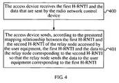
- FIG. 4 is a flowchart of yet still another method for data transmission according to an embodiment of the present invention. As shown in FIG. 4 , the method for data transmission according to this embodiment may specifically be as follows.
- the access device receives the first H-RNTI and the data that are sent by the radio network control device.
- the Node B receives an FP data packet that is sent by the RNC and includes the first H-RNTI assigned to the UE receiving the data and the data.
- the access device sends, according to the prestored mapping relationship between the first H-RNTI and the second H-RNTI of the relay node accessed by the user equipment, the first H-RNTI and the data to the relay node corresponding to the second H-RNTI so that the relay node sends the data to the user equipment corresponding to the first H-RNTI.
- the Node B parses the FP data packet to obtain the first H-RNTI of the UE, obtains, according to the mapping relationship, stored by the Node B, between the first H-RNTI of the UE and the second H-RNTI of the RN accessed by the UE, the second H-RNTI corresponding to the first H-RNTI, and sends the first H-RNTI of the UE and the data to be sent to the UE to the RN corresponding to the second H-RNTI so that the RN sends, according to the first H-RNTI, the data to the UE corresponding to the first H-RNTI.
- the Node B when sending the data to the RN, adds the second H-RNTI of the RN on the HS-SCCH of the air interface so that when detecting the second H-RNTI the same as that configured for the RN, the RN receives and parses the first H-RNTI of the UE and the data to be sent to the UE to obtain the first H-RNTI.
- the RN sends, according to the obtained first H-RNTI, the data to the UE corresponding to the first H-RNTI.
- the RN when sending the data packet to the UE, the RN also adds the first H-RNTI of the UE on the HS-SCCH of the air interface so that on the UE side, after detecting that the first H-RNTI is consistent with the first H-RNTI configured for the UE, the UE receives the data sent by the RN to the UE.
- the RN is introduced in the HSDPA network, and further, the first H-RNTI and the second H-RNTI are respectively assigned to the UE accessing the RN and the RN, and the mapping relationship between the first H-RNTI and the second H-RNTI is established and sent to the Node B so that the Node B sends, according to the mapping relationship, the data to be sent to the UE to the UE accurately by using the RN accessed by the UE.
- the coverage capability of the cell edge is enhanced, and the data can be sent accurately and effectively, thus further improving the efficiency in transmitting data to the UE at the cell edge.
- the method for data transmission further includes: receiving and storing, by the access device, the mapping relationship that is sent by the radio network control device and established between the second H-RNTI assigned to the relay node sending the network access request and the first H-RNTI assigned to the user equipment accessing the relay node.
- the Node B receives the mapping relationship, sent by the RNC, between the first H-RNTI of the UE and the second H-RNTI of the RN accessed by the UE and stores the mapping relationship in the Node B.
- the Node B manages and maintains the mapping relationship between the first H-RNTI of the UE and the second H-RNTI of the RN accessed by the UE, the mapping relationship is established by the RNC and then sent to the Node B, which may be as follows.
- the RNC After establishing the mapping relationship, the RNC sends the mapping relationship to the Node B through the Iub interface for storage by the Node B so that subsequently, the Node B can send, according to the mapping relationship, the data to be sent to the UE to the UE accurately by using the RN accessed by the UE.
- the mapping relationship is established between the first H-RNTI of the UE and the second H-RNTI of the RN accessed by the UE to ensure that the access network can send the delivered data to the destination UE accurately and effectively by using the RN, thus effectively ensuring the data transmission efficiency.
- FIG. 5 is a signaling diagram of a method for data transmission according to an embodiment of the present invention. As shown in FIG. 5 , the method for data transmission according to this embodiment may specifically be as follows.
- An RN accesses the network, and the RNC assigns a second H-RNTI to the RN.
- the RN sends a network access request to the RNC by using the Node B, and after receiving the network access request of the RN, the RNC assigns a second H-RNTI to the RN and notifies the second H-RNTI to the Node B through the Iub interface, and the Node B notifies the second H-RNTI to the RN.
- a UE accessing the RN initiates a service request, and the RNC assigns a first H-RNTI to the UE.
- the RN For example, after an RN is introduced at a cell edge, the RN covers UEs within a certain area. A UE accesses the RN within this service scope, and after accessing the RN, the UE sends an HSDPA service request to the access network.
- the RNC on the network side assigns a first H-RNTI to the UE and notifies the first H-RNTI to the Node B through the Iub interface, and the Node B notifies, by using the RN, the first H-RNTI to the UE, under the RN, that initiates the HSDPA service request.
- the RNC establishes a mapping relationship between the first H-RNTI of the UE and the second H-RNTI of the RN accessed by the UE.
- the RNC establishes the mapping relationship between the first H-RNTI of the UE and the second H-RNTI of the RN accessed by the UE, and manages and maintains the mapping relationship.
- the mapping relationship established by the RNC is equivalent to binding the UE and the RN accessed by the UE.
- the mapping relationship needs to be modified and updated.
- the RNC sends the first H-RNTI, the second H-RNTI and the data to the Node B.
- the RNC sends the first H-RNTI, the second H-RNTI and the data to the Node B.
- the RNC sends the FP data packet as shown in the foregoing Table 1 to the Node B.
- the FP header of the FP data packet carries the second H-RNTI of the RN accessed by the UE that is configured to receive the data, and the DATA part includes the first H-RNTI assigned to the UE and the data to be sent to the UE.
- the Node B sends the first H-RNTI and the data to the RN corresponding to the second H-RNTI.
- the Node B After receiving from the RNC the first H-RNTI of the UE, the second H-RNTI of the RN accessed by the UE and the data to be sent to the UE, the Node B first performs parsing to obtain the second H-RNTI carried in the header of the FP data packet, and then sends the first H-RNTI assigned to the UE and the data to be sent to the UE to the RN corresponding to the second H-RNTI.
- the Node B when sending the data to the RN, the Node B adds the second H-RNTI of the RN on the HS-SCCH of the air interface so that after the corresponding RN detects the second H-RNTI, the RN receives the first H-RNTI and the data that are sent by the Node B to the RN.
- the RN sends the data to the UE corresponding to the first H-RNTI.
- the RN After receiving the first H-RNTI and the data that are sent by the Node B, the RN performs parsing to obtain the first H-RNTI, and then sends the data to the UE corresponding to the first H-RNTI.
- the RN when sending the data to the UE, the RN adds the first H-RNTI of the UE on the HS-SCCH of the air interface so that on the UE side, after detecting that the first H-RNTI is consistent with the first H-RNTI configured for the UE, the UE receives the data sent by the RN to the UE.
- the RN is introduced in the HSDPA network, and further, the first H-RNTI and the second H-RNTI are respectively assigned to the UE accessing the RN and the RN, the mapping relationship between the first H-RNTI and the second H-RNTI is established; the RNC sends, according to the mapping relationship, the first H-RNTI of the UE, the second H-RNTI of the RN and the data to be sent to the UE to the Node B so that the Node B sends, according to the second H-RNTI, the first H-RNTI and the data to the RN, and the RN sends, according to the first H-RNTI, the data to the corresponding UE.
- the coverage capability of the cell edge is enhanced, and the data can be sent to the UE accurately and effectively, thus improving the efficiency in transmitting data to the UE at the cell edge.
- FIG. 6 is a signaling diagram of a method for data transmission according to an embodiment of the present invention. Unlike the embodiment shown in FIG. 5 , in this embodiment, the Node B manages and maintains the mapping relationship between the first H-RNTI of the UE and the second H-RNTI of the RN accessed by the UE. As shown in FIG. 6 , the method for data transmission according to this embodiment may specifically be as follows.
- the RN accesses the network, and the RNC assigns a second H-RNTI to the RN.
- a UE accessing the RN initiates a service request, and the RNC assigns a first H-RNTI to the UE.
- the RNC establishes a mapping relationship between the first H-RNTI of the UE and the second H-RNTI of the RN accessed by the UE.
- the implementation procedure of 20-22 is similar to that of 10-12 in the embodiment shown in FIG. 5 , the details of which can be seen in the foregoing embodiment and is not repeatedly described here.
- the RNC sends the mapping relationship to the Node B.
- the Node B manages and maintains the mapping relationship between the first H-RNTI of the UE and the second H-RNTI of the RN accessed by the UE, and after establishing the mapping relationship, the RNC sends the mapping relationship to the Node B and the Node B stores the mapping relationship.
- the mapping relationship established by the RNC binds the UE and the RN accessed by the UE.
- the mapping relationship needs to be modified and updated. For example, the modification of the mapping relationship is still accomplished by the RNC, and after modifying the mapping relationship, the RNC sends the modified mapping relationship to the Node B.
- the RNC sends to the Node B the first H-RNTI of the UE and the data to be sent to the UE.
- the RNC sends to the Node B the FP data packet as shown in the foregoing Table 2.
- the FP data packet includes the first H-RNTI of the UE and the data of the UE.
- the Node B sends, according to the prestored mapping relationship, the first H-RNTI and the data to the RN corresponding to the second H-RNTI.
- the Node B after receiving the FP data packet sent by the RNC, the Node B first performs parsing to obtain the first H-RNTI of the UE, and then sends, according to the prestored mapping relationship between the first H-RNTI of the UE and the second H-RNTI of the RN accessed by the UE, the first H-RNTI and the data to the RN corresponding to the second H-RNTI.
- the Node B when sending the first H-RNTI and the data to the RN, the Node B adds the second H-RNTI of the RN on the HS-SCCH of the air interface so that after the corresponding RN detects the second H-RNTI the same as that configured for the RN, the RN receives the first H-RNTI and the data that are sent by the Node B to the RN.
- the RN sends the data to the UE corresponding to the first H-RNTI.
- the RN After receiving the first H-RNTI and the data that are sent by the Node B, the RN performs parsing to obtain the first H-RNTI, and then sends the data to the UE corresponding to the first H-RNTI.
- the RN when sending the data to the UE, the RN adds the first H-RNTI of the UE on the HS-SCCH of the air interface so that on the UE side, after detecting that the first H-RNTI is consistent with the first H-RNTI configured for the UE, the UE receives the data sent by the RN to the UE.
- the RN is introduced in the HSDPA network, and further, the first H-RNTI and the second H-RNTI are respectively assigned to the UE accessing the RN and the RN, and the mapping relationship between the first H-RNTI and the second H-RNTI is established and sent to the Node B.
- the RNC sends the first H-RNTI and the data to the Node B, the Node B sends, according to the prestored mapping relationship, the first H-RNTI and the data to the RN corresponding to the second H-RNTI, and the RN sends the data to the UE corresponding to the first H-RNTI.
- the program may be stored in a computer readable storage medium. When the program runs, the steps of the aforementioned method embodiments are performed.
- the storage medium may be any medium capable of storing program codes, such as a ROM, a RAM, a magnetic disk or an optical disk.
- FIG. 7 is a schematic structural diagram of a radio network control device according to an embodiment of the present invention.
- the radio network control device according to this embodiment may include: an obtaining module 30 and a sending module 31.
- the obtaining module 30 is configured to obtain a prestored mapping relationship between a first H-RNTI of a user equipment and a second H-RNTI of a relay node accessed by the user equipment; and the sending module 31 is configured to send, according to the mapping relationship, the first H-RNTI, the second H-RNTI and data to an access device so that the access device sends the data to the user equipment corresponding to the first H-RNTI by using the relay node corresponding to the second H-RNTI.
- the radio network control device may be an RNC.
- the obtaining module 30 is configured to obtain the mapping relationship, prestored in the RNC, between the first H-RNTI of the UE and the second H-RNTI of the RN accessed by the UE.
- the sending module 31 is connected to the obtaining module 30, and sends, according to the mapping relationship obtained by the obtaining module 30, the first H-RNTI, the second H-RNTI and the data to the Node B so that the Node B sends, according to the second H-RNTI, the first H-RNTI and the data to the RN corresponding to the second H-RNTI, and the RN sends the data to the UE corresponding to the first H-RNTI.
- the implementation mechanism of data transmission by the radio network control device according to this embodiment and between the modules in the radio network control device is the same as that of the embodiment shown in FIG. 1 , the details of which can also be seen in the relevant description of the foregoing embodiment and is not repeatedly described here.
- the two modules are used to implement data transmission to the UE at the cell edge within the coverage of the RN by using the RN in the HSDPA network where the RN is introduced.
- the coverage capability of the cell edge is enhanced, and it is further ensured that the data can be sent accurately and effectively to the destination UE, thus improving the efficiency in transmitting data to the UE at the cell edge.
- FIG. 8 is a schematic structural diagram of another radio network control device according to an embodiment of the present invention. As shown in FIG. 8 , on the basis of the embodiment shown in FIG. 7 , the radio network control device according to this embodiment further includes: a first assigning module 32, a second assigning module 33 and a processing module 34.
- the first assigning module 32 is configured to assign the second H-RNTI to the relay node according to a network access request sent by the relay node; the second assigning module 33 is configured to assign, according to a service request sent by the user equipment accessing the relay node, the first H-RNTI to the user equipment; and the processing module 34 is configured to establish and store the mapping relationship between the first H-RNTI of the user equipment and the second H-RNTI of the relay node accessed by the user equipment.
- the radio network control device may be an RNC.
- the first assigning module 32 assigns the second H-RNTI to the newly introduced RN according to the network access request of the RN; the second assigning module 33 assigns the first H-RNTI to the UE accessing the RN according to the service request initiated by the UE; and the processing module 34 is connected to the first assigning module 32 and the second assigning module 33 respectively, and establishes a mapping relationship between the first H-RNTI of the UE that is obtained by the second assigning module 33 and the second H-RNTI of the RN that is obtained by the first assigning module 32 and stores the mapping relationship in the RNC so that in subsequent delivery of data, the obtaining module 30 in the RNC obtains the mapping relationship.
- the implementation mechanism of data transmission by the radio network control device according to this embodiment and between the modules in the radio network control device is the same as that of the subsequent parts (1) to (3) of the embodiment shown in FIG. 1 , the details of which can also be seen in the relevant description of the foregoing embodiment and is not repeatedly described here.
- the modules are used to implement the establishment of the mapping relationship between the first H-RNTI of the UE and the second H-RNTI of the RN accessed by the UE to ensure that the access network can send the delivered data to the UE accurately and effectively by the RN, thus effectively ensuring the data transmission efficiency.
- FIG. 9 is a schematic structural diagram of still another radio network control device according to an embodiment of the present invention.
- the radio network control device may specifically include: a first assigning module 40, a second assigning module 41, an establishing module 42, a first sending module 43 and a second sending module 44.
- the first assigning module 40 is configured to assign the second H-RNTI to the relay node according to a network access request sent by the relay node; the second assigning module 41 is configured to assign, according to a service request sent by the user equipment accessing the relay node, the first H-RNTI to the user equipment; the establishing module 42 is configured to establish a mapping relationship between the first H-RNTI of the user equipment and the second H-RNTI of the relay node accessed by the user equipment; the first sending module 43 is configured to send the mapping relationship to an access device; and the second sending module 44 is configured to send the first H-RNTI and data to the access device so that the access device sends, according to the mapping relationship, the data to the user equipment corresponding to the first H-RNTI by using the relay node corresponding to the second H-RNTI.
- the radio network control device may be an RNC.
- the first assigning module 40 assigns the second H-RNTI to the newly introduced RN according to the network access request of the RN; the second assigning module 41 assigns the first H-RNTI to the UE accessing the RN according to the service request initiated by the UE; the establishing module 42 is connected to the first assigning module 40 and the second assigning module 41 respectively, and establishes a mapping relationship between the first H-RNTI of the UE that is obtained by the second assigning module 41 and the second H-RNTI of the RN that is obtained by the first assigning module 40; the first sending module 43 is connected to the establishing module 42 and sends to the Node B the mapping relationship established by the establishing module 42; and the second sending module 44 sends the first H-RNTI and the data to the Node B so that the Node B sends, according to the received mapping relationship, sent by the first sending module 43, between the first H-RNTI and the second H-RNTI, the
- the implementation mechanism of data transmission by the radio network control device according to this embodiment and between the modules in the radio network control device is the same as that of the embodiment shown in FIG. 3 , the details of which can also be seen in the relevant description of the foregoing embodiment and is not repeatedly described here.
- the modules are used to implement data transmission to the UE at the cell edge accurately and effectively in the HSDPA network where the RN is introduced.
- the coverage capability of a cell edge is enhanced, and the efficiency in transmitting data to the UE at the cell edge is further improved.
- FIG. 10 is a schematic structural diagram of an access device according to an embodiment of the present invention. As shown in FIG. 10 , the access device according to this embodiment may specifically include: a receiving module 50 and a sending module 51.
- the receiving module 50 is configured to receive the first H-RNTI of the user equipment, the second H-RNTI of the relay node accessed by the user equipment and the data that are sent by the radio network control device according to the mapping relationship between the first H-RNTI and the second H-RNTI; and the sending module 51 is configured to send, according to the second H-RNTI, the first H-RNTI and the data to the relay node corresponding to the second H-RNTI so that the relay node sends the data to the user equipment corresponding to the first H-RNTI.
- the access device may be a Node B.
- the receiving module 50 receives the first H-RNTI of the UE, the second H-RNTI of the RN accessed by the UE and the data that are sent by the RNC according to the mapping relationship between the first H-RNTI and the second H-RNTI; and the sending module 51 is connected to the receiving module 50, and is configured to parse the received content to obtain the second H-RNTI, and send the first H-RNTI and the data to the RN corresponding to the second H-RNTI, and the RN sends the data to the UE corresponding to the first H-RNTI.
- the modules are used to implement data transmission to the UE at the cell edge accurately and effectively in the HSDPA network where the RN is connected.
- the coverage capability of a cell edge is enhanced, and the efficiency in transmitting data to the UE at the cell edge is further improved.
- FIG. 11 is a schematic structural diagram of another access device according to an embodiment of the present invention. As shown in FIG. 11 , the access device according to this embodiment may specifically include: a first receiving module 60 and a sending module 61.
- the first receiving module 60 is configured to receive the first H-RNTI of the user equipment and the data that are sent by the radio network control device; the sending module 61 is configured to send, according to the mapping relationship between the first H-RNTI and the second H-RNTI of the relay node accessed by the user equipment, the first H-RNTI and the data to the user equipment corresponding to the first H-RNTI by using the relay node corresponding to the second H-RNTI.
- the access device may be a Node B.
- the first receiving module 60 receives from the RNC the first H-RNTI of the UE and the data to be sent to the UE; and the sending module 61 is connected to the first receiving module 60, and parses, according to the prestored mapping relationship between the first H-RNTI of the UE and the second H-RNTI of the RN accessed by the UE, the content received by the first receiving module 60 to obtain the second H-RNTI corresponding to the first H-RNTI, and then sends the first H-RNTI and the data to the RN corresponding to the second H-RNTI so that the RN sends, according to the received first H-RNTI, the data to the UE corresponding to the first H-RNTI.
- the modules are used to implement data transmission to the UE at the cell edge accurately and effectively in the HSDPA network where the RN is connected.
- the coverage capability of a cell edge is enhanced, and the efficiency in transmitting data to the UE at the cell edge is further improved.
- the access device may further include a second receiving module 62, where the second receiving module 62 is configured to receive the mapping relationship that is sent by the radio network control device and established between the second H-RNTI assigned to the relay node sending the network access request and the first H-RNTI assigned to the user equipment accessing the relay node.
- the second receiving module 62 is connected to the sending module 61.
- the second receiving module 62 receives the mapping relationship, sent by the RNC, between the first
- the mapping relationship is a mapping relationship, established by the RNC, between the second H-RNTI assigned to the RN sending the network access request and the first H-RNTI of the UE accessing the RN, and is then sent by the RNC to the Node B.
- the sending module 61 of the Node B obtains, according to the mapping relationship received by the second receiving module 62, the second H-RNTI corresponding to the first H-RNTI received by the first receiving module 60.
- the sending module 61 sends the first H-RNTI and the data that are received by the first receiving module 60 to the RN corresponding to the second H-RNTI, and the RN sends, according to the received first H-RNTI, the data to the UE corresponding to the first H-RNTI.
- FIG. 12 is a schematic structural diagram of a system for data transmission according to an embodiment of the present invention.
- the system 70 for data transmission according to this embodiment may specifically include: a relay node 71, an access device 72 and a radio network control device 73.
- a user equipment 74 configured to receive data is also included.
- the radio network control device 73 is configured to obtain a prestored mapping relationship between a first H-RNTI of the user equipment 74 and a second H-RNTI of the relay node 71 accessed by the user equipment 74; and send, according to the mapping relationship, the first H-RNTI, the second H-RNTI and the data to the access device 72.
- the access device 72 is configured to receive the first H-RNTI, the second H-RNTI and the data that are sent by the radio network control device 73; and send, according to the second H-RNTI, the first H-RNTI and the data to the relay node 71.
- the relay node 71 is configured to receive the first H-RNTI and the data that are sent by the access device 72; and send the data to the user equipment 74 corresponding to the first H-RNTI.
- the radio network control device 73 is connected to the access device 72.
- the radio network control device 73 first obtains a mapping relationship, prestored by the radio network control device 73, between the first H-RNTI of the user equipment and the second H-RNTI of the relay node 71 accessed by the user equipment 74, and sends the first H-RNTI, the second H-RNTI and the data to the access device 72 according to the mapping relationship.
- the access device 72 is connected to the relay node 71.
- the access device 72 After receiving the first H-RNTI, the second H-RNTI and the data that are sent by the radio network control device 73, the access device 72 performs parsing to obtain the second H-RNTI, and then sends the first H-RNTI and the data to the relay node 71 corresponding to the second H-RNTI.
- the relay node 71 is connected to the user equipment 74, and the relay node 71 sends, according to the received first H-RNTI, the data to the user equipment 74 corresponding to the first H-RNTI.
- the radio network control device 73 in the system 70 for data transmission according to this embodiment may be an RNC, and specifically, the radio network control device in any embodiment shown in FIG. 7 or FIG. 8 may be used.
- the access device 72 in the system 70 for data transmission according to this embodiment may be a Node B, and specifically, the access device in the embodiment shown in FIG. 10 may be used.
- the relay node 71 in the system 70 for data transmission according to this embodiment may be the RN as described in the foregoing embodiments.
- the user equipment 74 configured to receive data in this embodiment may be the UE as described in the foregoing embodiments.
- the radio network control device 73 manages and maintains the mapping relationship between the first H-RNTI of the user equipment 74 and the second H-RNTI of the relay node 71 accessed by the user equipment 74.
- the implementation mechanism of data transmission by the relay node 71, the access device 72 and the radio network control device 73 in the system 70 for data transmission according to this embodiment is the same as the implementation mechanism in the embodiment shown in FIG. 7, FIG. 8 or FIG. 10 , the details of which can be seen in the relevant description of the foregoing relevant embodiments and is not repeatedly described here.
- the relay node is introduced in the HSDPA network so that the coverage capability of the cell edge is enhanced, and the radio network control device can transmit, according to the prestored mapping relationship between the first H-RNTI of the user equipment and the second H-RNTI of the relay node accessed by the user equipment, the data to be sent to the user equipment to the user equipment within the coverage of the relay node accurately by using the access device and the relay node.
- the efficiency in transmitting data to the user equipment at the cell edge is further effectively improved.
- FIG. 13 is a schematic structural diagram of another system for data transmission according to an embodiment of the present invention.
- the system 80 for data transmission according to this embodiment may specifically include: a relay node 81, an access device 82 and a radio network control device 83.
- a user equipment 84 configured to receive data is also included.
- the radio network control device 83 is configured to assign the second H-RNTI to the relay node 81 according to a network access request sent by the relay node 81; assign, according to a service request sent by the user equipment 84 accessing the relay node 81, the first H-RNTI to the user equipment 84; establish a mapping relationship between the first H-RNTI of the user equipment 84 and the second H-RNTI of the relay node 81 accessed by the user equipment 84; send the mapping relationship to the access device 82; and send the first H-RNTI and data to the access device 82.
- the access device 82 is configured to receive the first H-RNTI of the user equipment 84 and the data that are sent by the radio network control device 83; and send the first H-RNTI and the data to the relay node 81 corresponding to the second H-RNTI according to the received mapping relationship sent by the radio network control device 83; and the relay node 81 is configured to receive the first H-RNTI and the data that are sent by the access device 82, and send the data to the user equipment 84 corresponding to the first H-RNTI.
- the radio network control device 83 is connected to the access device 82, the access device 82 is connected to the relay node 81, and the relay node 81 is further connected to the user equipment 84 falling within the service scope of the relay node 81.
- the radio network control device 83 assigns the second H-RNTI to the relay node 81 according to the network access request sent by the relay node 81 by using the access device 82, and notifies the second H-RNTI to the access device 82 through the Iub interface so that the access device 82 notifies the second H-RNTI to the relay node 81.
- the radio network control device 83 assigns the first H-RNTI to the user equipment 84 accessing the relay node 81 according to the service request sent by the user equipment 84, and similarly, notifies the first H-RNTI to the user equipment 84 by using the access device 82 and the relay node 81 accessed by the user equipment 84.
- the radio network control device 83 establishes the mapping relationship between the first H-RNTI of the user equipment 84 and the second H-RNTI of the relay node 81 accessed by the user equipment 84.
- the radio network control device 83 sends the established mapping relationship to the access device 82, and then sends to the access device 82 the first H-RNTI of the user equipment 84 and the data to be sent to the user equipment 84.
- the access device 82 parses the received content to obtain the first H-RNTI, and then obtains the second H-RNTI corresponding to the first H-RNTI according to the received mapping relationship sent by the radio network control device 83, and sends the first H-RNTI and the data to the relay node 81 corresponding to the second H-RNTI so that the relay node 81 sends, according to the received first H-RNTI, the data to the user equipment 84 corresponding to the first H-RNTI.
- the radio network control device 83 in the system 80 for data transmission according to this embodiment may be an RNC, and specifically, the radio network control device in the embodiment shown in FIG. 9 may be used.
- the access device 82 in the system 80 for data transmission according to this embodiment may be a Node B, and specifically, the access device in the embodiment shown in FIG. 11 may be used.
- the relay node 81 in the system 80 for data transmission according to this embodiment may be the RN as described in the foregoing embodiments.
- the user equipment 84 of this embodiment may be the UE as described in the foregoing embodiments.
- the implementation mechanism of data transmission by the relay node 81, the access device 82 and the radio network control device 83 in the system 80 for data transmission according to this embodiment is the same as the implementation mechanism in the embodiment shown in FIG. 9 or FIG. 11 , the details of which can be seen in the relevant description of the foregoing relevant embodiments and is not repeatedly described here.
- the access device 82 manages and maintains the mapping relationship between the first H-RNTI of the user equipment 84 and the second H-RNTI of the relay node 81 accessed by the user equipment 84.
- the relay node is introduced in the HSDPA network so that the coverage capability of the cell edge is enhanced, and by using the mapping relationship, prestored by the access device, between the first H-RNTI of the user equipment and the second H-RNTI of the relay node accessed by the user equipment, the received data that is sent by the radio network control device to the user equipment can be transmitted to the user equipment within the coverage of the relay node accurately by using the relay node.
- the efficiency in transmitting data to the user equipment at the cell edge is further effectively improved.
- the disclosed system, apparatus and method may be implemented by other means without departing from the spirit and scope of the present application.
- the forgoing apparatus embodiments are only exemplary.
- the division of the units is only a logic function division, and there may be other means of division in actual implementation, for example, multiple units or components may be combined or integrated into another system, or some features may be ignored, or not executed.
- the units described as separate components may or may not be physically separated, and the components shown as units may or may not be physical units, that is, may be located in one place or may be distributed to at least two network units. Part or all of the modules may be selected according to the actual needs to implement the objective of the solutions of the embodiments. Persons of ordinary skill in the art may understand and implement the embodiments without creative efforts.
- the present invention may be implemented by means of software and a necessary general hardware platform, or of course, by means of hardware, but the former is preferred in many cases.
- the technical solutions of the present invention or the portions contributing to the prior art or part or all of the technical solutions may be embodied in the form of a software product.
- the computer software product is stored in a storage medium and includes several instructions to cause a computer device (which may be a personal computer, a server, a network device, and so on) to execute all or part of the steps of the method described in the embodiments of the present invention.
- the storage medium may be any medium capable of storing program codes, such as a USB flash drive, a removable hard disk, a read only memory (ROM), a random access memory (RAM), a magnetic disk or an optical disk.
Landscapes
- Engineering & Computer Science (AREA)
- Computer Networks & Wireless Communication (AREA)
- Signal Processing (AREA)
- Mobile Radio Communication Systems (AREA)
Description
- Embodiments of the present invention relate to the field of data transmission technologies, and in particular, to a method and system for data transmission.
- In order to accommodate multimedia services' growing demand for high-speed data transmission, the Third Generation Partnership Project (3rd Generation Partnership Project, hereinafter referred to as 3GPP) proposed the high-speed downlink packet access (High Speed Downlink Packet Access, hereinafter referred to as HSDPA) technology. HSDPA is a packet-based data service, and specifically, is an optimization and evolution of a packet service in the downlink direction, namely, the direction from a radio access network to a mobile terminal. Therefore, HSDPA is capable of enhancing the downlink part of mobile data transmission, thereby implementing high-speed data transmission.
- In the existing HSDPA technology, the transmission mode using a 2-ms transmission time interval (Transmission Time Interval, hereinafter referred to as TTI) is widely used for its low data transmission delay and high data transmission rate.
- The transmission mode of a 2-ms TTI that is generally used in the existing HSDPA technology improves the data transmission rate, but the transmission mode of the 2-ms TTI belongs to short frame transmission, reducing the downlink coverage capability of a cell edge. Consequently, the efficiency in transmitting data to a user equipment at the cell edge is reduced.
- The prior art
US 2008/0188220 A1 discloses a method and an apparatus for a cell update. After selecting a target cell, system information is read from the target cell including high speed downlink shared channel (HS-DSCH) common system information. A radio network temporary identity (RNTI) received in a source cell is cleared. An HS-DSCH medium access control entity is configured based on the HS-DSCH common system information. High speed downlink packet access transmission is then received in the target cell. - In one aspect, the present invention is directed to a method and system for data transmission, capable of effectively improving the efficiency in transmitting data to a user equipment at a cell edge.
- In one aspect, the present invention provides a method for data transmission, applied in an HSDPA network, where the method includes:
- sending, according to a mapping relationship between a first H-RNTI of a user equipment and a second H-RNTI of a relay node accessed by the user equipment, data to the user equipment corresponding to the first H-RNTI by using the relay node corresponding to the second H-RNTI.
- In another aspect, the present invention provides a radio network control device, where the device includes:
- an obtaining module, configured to obtain a prestored mapping relationship between a first H-RNTI of a user equipment and a second H-RNTI of a relay node accessed by the user equipment; and
- a sending module, configured to send, according to the mapping relationship, the first H-RNTI, the second H-RNTI and data to an access device so that the access device sends the data to the user equipment corresponding to the first H-RNTI by using the relay node corresponding to the second H-RNTI.
- In another aspect, the present invention provides an access device, where the device includes:
- a receiving module, configured to receive a first H-RNTI of a user equipment, a second H-RNTI of a relay node accessed by the user equipment and data that are sent by a radio network control device according to a mapping relationship between the first H-RNTI and the second H-RNTI; and
- a sending module, configured to send, according to the second H-RNTI, the first H-RNTI and the data to the relay node corresponding to the second H-RNTI so that the relay node sends the data to the user equipment corresponding to the first H-RNTI.
- In another aspect, the present invention provides a system for data transmission, where the system includes: a relay node, an access device and a radio network control device.
- The radio network control device is configured to obtain a prestored mapping relationship between a first H-RNTI of a user equipment and a second H-RNTI of a relay node accessed by the user equipment; and send, according to the mapping relationship, the first H-RNTI, the second H-RNTI and data to the access device.
- The access device is configured to receive the first H-RNTI, the second H-RNTI and the data that are sent by the radio network control device; and send, according to the second H-RNTI, the first H-RNTI and the data to the relay node.
- The relay node is configured to receive the first H-RNTI and the data that are sent by the access device; and send the data to the user equipment corresponding to the first H-RNTI.
- The method and system for data transmission described above enhance the downlink coverage capability of a cell edge and further improve the efficiency in transmitting data to a user equipment at the cell edge.
- To make the technical solutions in the embodiments of the present invention or in the prior art clearer, the accompanying drawings for the description of the embodiments or the prior art are briefly described in the following. Evidently, the accompanying drawings in the following description illustrate some embodiments of the present invention only and persons of ordinary skill in the art may derive, without any creative efforts, other drawings based on these drawings.
-
FIG. 1 is a flowchart of a method for data transmission according to an embodiment of the present invention; -
FIG. 2 is a flowchart of another method for data transmission according to an embodiment of the present invention; -
FIG. 3 is a flowchart of still another method for data transmission according to an embodiment of the present invention; -
FIG. 4 is a flowchart of yet still another method for data transmission according to an embodiment of the present invention; -
FIG. 5 is a signaling diagram of a method for data transmission according to an embodiment of the present invention; -
FIG. 6 is a signaling diagram of a method for data transmission according to an embodiment of the present invention; -
FIG. 7 is a schematic structural diagram of a radio network control device according to an embodiment of the present invention; -
FIG. 8 is a schematic structural diagram of another radio network control device according to an embodiment of the present invention; -
FIG. 9 is a schematic structural diagram of still another radio network control device according to an embodiment of the present invention; -
FIG. 10 is a schematic structural diagram of an access device according to an embodiment of the present invention; -
FIG. 11 is a schematic structural diagram of another access device according to an embodiment of the present invention; -
FIG. 12 is a schematic structural diagram of a system for data transmission according to an embodiment of the present invention; and -
FIG. 13 is a schematic structural diagram of another system for data transmission according to an embodiment of the present invention. - To make the objectives, technical solutions and advantages of the embodiments of the present invention clearer, the technical solutions in the embodiments of the present invention are described clearly and completely in the following with reference to the accompanying drawings in the embodiments of the present invention. Evidently, the described embodiments are only some embodiments of the present invention, rather than all embodiments of the present invention. All other embodiments that persons of ordinary skill in the art may derive, without any creative efforts, based on the embodiments of the present invention fall within the protection scope of the present invention.
- In a downlink part of an HSDPA network, multiple user equipments (User Equipment, hereinafter referred to as UE) transmit data simultaneously on a high-speed downlink shared channel (High-Speed Downlink Shared Channel, hereinafter referred to as HS-DSCH), and therefore, each UE needs to be identified so that different UEs are capable of receiving their own data on the data channel. A control radio network controller (Control Radio Network Controller, hereinafter referred to as CRNC) configures an HS-DSCH radio network temporary identity (HS-DSCH Radio Network Temporary Identity, hereinafter referred to as H-RNTI) respectively for different UEs to identify different UEs. The CRNC notifies an H-RNTI to a Node B and a UE simultaneously. If detecting, on a high-speed shared control channel (High-Speed Shared Control Channel, hereinafter referred to as HS-SCCH), that an H-RNTI in the downlink data is consistent with the configured H-RNTI, the UE receives data on a corresponding high-speed physical downlink shared channel (High-Speed Physical Downlink Shared Channel, hereinafter referred to as HS-PDSCH).
- A radio access network in the HSDPA network of the embodiments of the present invention includes a radio network controller (Radio Network Controller, hereinafter referred to as RNC) and a Node B, where data is transmitted between the RNC and the Node B according to the Frame Protocol (FP). The embodiments of the present invention are described in detail in the following with reference to the accompanying drawings and specific implementations.
- An embodiment of the present invention provides a method for data transmission. The method for data transmission is applied in an HSDPA network, and includes: sending, according to a mapping relationship between a first H-RNTI of a user equipment and a second H-RNTI of a relay node accessed by the user equipment, data to the user equipment corresponding to the first H-RNTI by using the relay node corresponding to the second H-RNTI.
- For example, in an HSDPA network where a relay node (Relay Node, hereinafter referred to as RN) is introduced at a cell edge, data to be sent to a UE may be sent, according to a mapping relationship between a first H-RNTI of the UE and a second H-RNTI of an RN accessed by the UE, to the UE accurately by using the RN .
- The method for data transmission according to this embodiment can enhance the downlink coverage capability of a cell edge and further improve the efficiency in transmitting data to a user equipment at the cell edge.
-
FIG. 1 is a flowchart of a method for data transmission according to an embodiment of the present invention. As shown inFIG. 1 , the method for data transmission according to this embodiment may be as follows. - 100: A radio network control device obtains a prestored mapping relationship between the first H-RNTI of the user equipment and the second H-RNTI of the relay node accessed by the user equipment.
- 101: The radio network control device sends, according to the mapping relationship, the first H-RNTI, the second H-RNTI and the data to an access device so that the access device sends the data to the user equipment corresponding to the first H-RNTI by using the relay node corresponding to the second H-RNTI.
- For example, an RNC manages and maintains a mapping relationship between a first H-RNTI of a UE and a second H-RNTI of an RN accessed by the UE. The RNC obtains the mapping relationship, prestored in the RNC, between the first H-RNTI of the UE and the second H-RNTI of the RN accessed by the UE, and then sends the first H-RNTI, the second H-RNTI and data, for example, sends an FP data packet including the first H-RNTI, the second H-RNTI and data, to an access device (for example, a Node B or a gateway; a Node B is used as an example of the access device below) through an Iub interface according to the mapping relationship. For example, the HSDPA FP data packet sent by the RNC to the Node B is specifically in the form shown in Table 1.
Table 1 FP header Second H-RNTI DATA - As shown in Table 1, the FP header of the data packet carries the second H-RNTI of the RN accessed by the UE that is configured to receive data, and the DATA part includes the first H-RNTI assigned to the UE and the data to be sent to the UE. In this way, it can be ensured that after receiving the FP data packet, the Node B parses the FP data packet to obtain the second H-RNTI carried in the FP header, and then sends the first H-RNTI and the data to the RN corresponding to the second H-RNTI accurately. When sending the data to the RN, the Node B adds the second H-RNTI of the RN on an HS-SCCH of an air interface so that after the corresponding RN detects that this second H-RNTI is consistent with the second H-RNTI configured for the RN, the RN receives the first H-RNTI and the data that are sent by the Node B to the RN. After receiving the first H-RNTI and the data, the RN performs parsing to obtain the first H-RNTI, sends the data to the UE corresponding to the first H-RNTI, and adds the first H-RNTI of the UE on the HS-SCCH of the air interface so that on the UE side, after the UE detects that the first H-RNTI is consistent with the first H-RNTI configured for the UE, the UE receives the data that is sent by the RN to the UE.
- In the method for data transmission according to this embodiment, the RN is introduced in the HSDPA network, and further, the RNC can accurately transmit, according to the prestored mapping relationship between the first H-RNTI of the UE and the second H-RNTI of the RN accessed by the UE, the data to be sent to the UE to the UE within the coverage of the RN by using the Node B and the RN. By using the technical solution of this embodiment, the coverage capability of the cell edge is enhanced, and the efficiency in transmitting data to the UE at the cell edge is further improved.
- In another embodiment of the present invention, for example, before sending the first H-RNTI, the second H-RNTI and the data to the access device in the foregoing embodiment, the method for data transmission may also be as follows.
- (1) The radio network control device assigns the second H-RNTI to the relay node according to a network access request sent by the relay node.
For example, after an RN is introduced at a cell edge, the RN sends a network access request to the RNC by using the Node B, and after receiving the network access request of the RN, the RNC assigns a second H-RNTI to the RN and notifies the second H-RNTI to the Node B through the Iub interface, and the Node B notifies the second H-RNTI to the RN. - (2) The radio network control device assigns, according to a service request sent by the user equipment accessing the relay node, the first H-RNTI to the user equipment.
For example, after an RN is introduced at the cell edge, a UE within the service scope of the RN is connected under the RN. After accessing the RN, the UE sends an HSDPA service request to the access network. When receiving the HSDPA service request and preparing for establishing an HSDPA service for the UE, the RNC on the network side assigns a first H-RNTI to the UE and notifies the first H-RNTI to the Node B through the Iub interface, and the Node B notifies, by using the RN, the first H-RNTI to the UE, under the RN, that initiates the HSDPA service request. - (3) The radio network control device establishes and stores the mapping relationship between the first H-RNTI of the user equipment and the second H-RNTI of the relay node accessed by the user equipment.
- For example, after the RNC assigns the second H-RNTI to the RN accessing the network and assigns the first H-RNTI to the UE accessing the RN, the RN establishes and stores the mapping relationship between the first H-RNTI of the UE and the second H-RNTI of the RN accessed by the UE. The mapping relationship binds the UE and the RN accessed by the UE. When the second H-RNTI of the RN or the first H-RNTI of the UE accessing the RN changes, the mapping relationship needs to be modified and updated.
- By introducing a relay node (Relay Node, hereinafter referred to as RN) at a cell edge of the HSDPA network, the embodiment of the present invention solves the low efficiency problem that the transmission mode of a 2-ms TTI used in the existing HSDPA technologies decreases the downlink coverage capability of the cell edge, resulting in a delay or an error in transmission of data to a UE at the cell edge and a failure to send data to the UE at the cell edge. In the embodiment of the present invention, after the relay node is introduced at the cell edge, the Node B is capable of sending the data to be sent to the UE within the coverage of the RN to the UE accurately by using the RN, effectively improving the efficiency in transmitting data to the UE at the cell edge.
-
FIG. 2 is a flowchart of another method for data transmission according to an embodiment of the present invention. As shown inFIG. 2 , the method for data transmission according to this embodiment may specifically be as follows. - 200: The access device receives the first H-RNTI of the user equipment, the second H-RNTI of the relay node accessed by the user equipment and the data that are sent by the radio network control device according to the mapping relationship between the first H-RNTI and the second H-RNTI.
- For example, in the HSDPA network, after an RN is added at a cell edge, an RNC assigns a first H-RNTI and a second H-RNTI respectively to a UE accessing the RN and the RN, and establishes a mapping relationship between the first H-RNTI and the second H-RNTI. Then, the RNC sends, according to the mapping relationship, the first H-RNTI, the second H-RNTI and data, for example, sends an FP data packet including the first H-RNTI, the second H-RNTI and data, to an access device (for example, a Node B or a gateway; for ease of description, a Node B is used as an example in the following description). Accordingly, the Node B receives the FP data packet, including the first H-RNTI, the second H-RNTI and the data, that is sent by the RNC. The FP data packet takes the form as shown in the foregoing Table 1. The FP header of the FP data packet carries the second H-RNTI of the RN accessed by the destination UE to which the data is sent, and the DATA part includes the first H-RNTI assigned to the UE and the data to be sent to the UE.
- 201: The access device sends, according to the second H-RNTI, the first H-RNTI and the data to the relay node corresponding to the second H-RNTI so that the relay node sends the data to the user equipment corresponding to the first H-RNTI.
- For example, the Node B sends, according to the second H-RNTI of the RN carried in the received FP data packet, the DATA part in Table 1, namely, the first H-RNTI and the data to be sent to the UE, to the RN corresponding to the second H-RNTI. The Node B adds the second H-RNTI of the RN on the HS-SCCH of the air interface so that upon detecting the second H-RNTI the same as that configured for the RN, the RN receives the first H-RNTI to be sent to the UE accessing the RN and the data to be sent to the UE and parses the received first H-RNTI and data to obtain the first H-RNTI. The RN sends, according to the obtained first H-RNTI, the data to the UE corresponding to the first H-RNTI. The RN adds the first H-RNTI of the UE on the HS-SCCH of the air interface so that after the UE detects that the first H-RNTI is consistent with the first H-RNTI configured for the UE, the UE receives the data sent by the RN to the UE.
- In the method for data transmission according to this embodiment, after the RN is connected under the Node B, the RNC in the HSDPA network sends, according to the mapping relationship between the first H-RNTI of the UE and the second H-RNTI of the RN accessed by the UE, the first H-RNTI, the second H-RNTI and the data to be sent to the UE to the Node B, and the Node B is capable of sending, according to the received second H-RNTI, the data to the UE corresponding to the first H-RNTI accurately by using the RN corresponding to the second H-RNTI. By using the technical solution of this embodiment, the coverage capability of the cell edge is enhanced, and the efficiency in transmitting data to the UE at the cell edge is further improved.
-
FIG. 3 is a flowchart of still another method for data transmission according to an embodiment of the present invention. As shown inFIG. 3 , the method for data transmission according to this embodiment may specifically be as follows. - 300: The radio network control device assigns the second H-RNTI to the relay node according to a network access request sent by the relay node.
- For example, after an RN is introduced at a cell edge, the RN sends a network access request to the RNC by using the Node B, and after receiving the network access request of the RN, the RNC assigns a second H-RNTI to the RN and notifies the second H-RNTI to the Node B through the Iub interface, and the Node B notifies the second H-RNTI to the RN.
- 301: The radio network control device assigns, according to a service request sent by the user equipment accessing the relay node, the first H-RNTI to the user equipment.
- For example, after an RN is introduced at a cell edge, the RN covers UEs within a certain area. After accessing the RN of the service scope where the UE is located, the UE sends an HSDPA service request to the access network. When receiving the HSDPA service request and preparing for establishing an HSDPA service for the UE, the RNC on the network side first assigns a first H-RNTI to the UE and notifies the first H-RNTI to the Node B through the Iub interface, and the Node B notifies, by using the RN, the first H-RNTI to the UE, under the RN, that initiates the HSDPA service request.
- 302: The radio network control device establishes the mapping relationship between the first H-RNTI of the user equipment and the second H-RNTI of the relay node accessed by the user equipment.
- For example, after the RNC assigns the second H-RNTI to the RN accessing the network and assigns the first H-RNTI to the UE accessing the RN, the RNC establishes the mapping relationship between the first H-RNTI of the UE and the second H-RNTI of the RN accessed by the UE and stores the mapping relationship in the RNC so that subsequently, the RNC sends data to the Node B according to the mapping relationship. The mapping relationship binds the UE and the RN accessed by the UE. When the second H-RNTI of the RN or the first H-RNTI of the UE accessing the RN changes, the mapping relationship needs to be modified and updated.
- 303: The radio network control device sends the mapping relationship to the access device for storage by the access device.
- For example, the RNC sends the mapping relationship to the corresponding Node B controlled by the RNC, and the Node B stores the mapping relationship. The RN locates within the service scope of the Node B.
- 304: The radio network control device sends the first H-RNTI and the data to the access device so that the access device sends, according to the prestored mapping relationship between the first H-RNTI of the user equipment and the second H-RNTI of the relay node accessed by the user equipment, the data to the user equipment corresponding to the first H-RNTI by using the relay node corresponding to the second H-RNTI.
- For example, after sending the mapping relationship to the corresponding Node B controlled by the RNC, the RNC sends the FP data packet shown in Table 2 to the Node B, where the DATA in the FP data packet includes the first H-RNTI of the destination UE to which the data is sent and the data to be sent to the UE. After receiving the FP data packet, the Node B parses the FP data packet to obtain the first H-RNTI of the UE, and obtains the second H-RNTI corresponding to the first H-RNTI according to the received mapping relationship between the first H-RNTI of the UE and the second H-RNTI of the RN accessed by the UE, and then sends the first H-RNTI of the UE and the data to be sent to the UE to the RN node corresponding to the second H-RNTI, that is, sends the first H-RNTI and the data to be sent to the UE to the RN node accessed by the UE, so that the RN sends the data to the UE corresponding to the first H-RNTI.
Table 2 FP header DATA - In another embodiment of the present invention, when sending the data to the RN, the Node B adds the second H-RNTI of the RN on the HS-SCCH of the air interface so that when detecting the second H-RNTI the same as that configured for the RN, the RN receives the first H-RNTI to be sent to the destination UE and the data to be sent to the UE and parses the received content to obtain the first H-RNTI. The RN sends, according to the obtained first H-RNTI, the data to be sent to the UE to the UE corresponding to the first H-RNTI. The RN adds the first H-RNTI of the UE on the HS-SCCH of the air interface so that after detecting that the first H-RNTI is consistent with the first H-RNTI configured for the UE, the UE receives the data sent by the RN to the UE.
- In the method for data transmission according to this embodiment, the RN is introduced in the HSDPA network, and further, the first H-RNTI and the second H-RNTI are respectively assigned to the UE accessing the RN and the RN, and the mapping relationship between the first H-RNTI and the second H-RNTI is established and sent to the Node B so that the Node B sends, according to the mapping relationship, the received data to be sent to the UE to the UE within the coverage of the RN accurately by using the RN. By using the technical solution of this embodiment, the coverage capability of the cell edge is enhanced, and the efficiency in transmitting data to the UE at the cell edge is further improved.
-
FIG. 4 is a flowchart of yet still another method for data transmission according to an embodiment of the present invention. As shown inFIG. 4 , the method for data transmission according to this embodiment may specifically be as follows. - 400: The access device receives the first H-RNTI and the data that are sent by the radio network control device.
- For example, the Node B receives an FP data packet that is sent by the RNC and includes the first H-RNTI assigned to the UE receiving the data and the data.
- 401: The access device sends, according to the prestored mapping relationship between the first H-RNTI and the second H-RNTI of the relay node accessed by the user equipment, the first H-RNTI and the data to the relay node corresponding to the second H-RNTI so that the relay node sends the data to the user equipment corresponding to the first H-RNTI.
- For example, after receiving the FP data packet sent by the RNC, the Node B parses the FP data packet to obtain the first H-RNTI of the UE, obtains, according to the mapping relationship, stored by the Node B, between the first H-RNTI of the UE and the second H-RNTI of the RN accessed by the UE, the second H-RNTI corresponding to the first H-RNTI, and sends the first H-RNTI of the UE and the data to be sent to the UE to the RN corresponding to the second H-RNTI so that the RN sends, according to the first H-RNTI, the data to the UE corresponding to the first H-RNTI.
- In another embodiment of the present invention, when sending the data to the RN, the Node B adds the second H-RNTI of the RN on the HS-SCCH of the air interface so that when detecting the second H-RNTI the same as that configured for the RN, the RN receives and parses the first H-RNTI of the UE and the data to be sent to the UE to obtain the first H-RNTI. The RN sends, according to the obtained first H-RNTI, the data to the UE corresponding to the first H-RNTI. In another embodiment of the present invention, when sending the data packet to the UE, the RN also adds the first H-RNTI of the UE on the HS-SCCH of the air interface so that on the UE side, after detecting that the first H-RNTI is consistent with the first H-RNTI configured for the UE, the UE receives the data sent by the RN to the UE.
- In the method for data transmission according to this embodiment, the RN is introduced in the HSDPA network, and further, the first H-RNTI and the second H-RNTI are respectively assigned to the UE accessing the RN and the RN, and the mapping relationship between the first H-RNTI and the second H-RNTI is established and sent to the Node B so that the Node B sends, according to the mapping relationship, the data to be sent to the UE to the UE accurately by using the RN accessed by the UE. By using the technical solution of this embodiment, the coverage capability of the cell edge is enhanced, and the data can be sent accurately and effectively, thus further improving the efficiency in transmitting data to the UE at the cell edge.
- In another embodiment of the present invention, for example, before 400 "The access device receives the first H-RNTI and the data that are sent by the radio network control device" in the foregoing embodiment, the method for data transmission further includes: receiving and storing, by the access device, the mapping relationship that is sent by the radio network control device and established between the second H-RNTI assigned to the relay node sending the network access request and the first H-RNTI assigned to the user equipment accessing the relay node.
- For example, before 400 in the embodiment shown in
FIG. 4 , the Node B receives the mapping relationship, sent by the RNC, between the first H-RNTI of the UE and the second H-RNTI of the RN accessed by the UE and stores the mapping relationship in the Node B. - Although in this embodiment, the Node B manages and maintains the mapping relationship between the first H-RNTI of the UE and the second H-RNTI of the RN accessed by the UE, the mapping relationship is established by the RNC and then sent to the Node B, which may be as follows.
- (a) The radio network control device assigns the second H-RNTI to the relay node according to a network access request sent by the relay node.
For example, after an RN is introduced at a cell edge, the RN sends a network access request to the RNC by using the Node B, and after receiving the network access request of the RN, the RNC assigns a second H-RNTI to the RN and notifies the second H-RNTI to the Node B through the Iub interface, and the Node B notifies the second H-RNTI to the RN. - (b) The radio network control device assigns, according to a service request sent by the user equipment accessing the relay node, the first H-RNTI to the user equipment.
For example, after an RN is introduced at a cell edge, the RN covers UEs within a certain area. After a UE falling within the service scope of the RN accesses the RN, the UE sends an HSDPA service request to the access network. When receiving the HSDPA service request and preparing for establishing an HSDPA service for the UE, the RNC on the network side first assigns a first H-RNTI to the UE and notifies the first H-RNTI to the Node B through the Iub interface, and the Node B notifies, by using the RN, the first H-RNTI to the UE, under the RN, that initiates the HSDPA service request. - (c) The radio network control device establishes the mapping relationship between the first H-RNTI of the user equipment and the second H-RNTI of the relay node accessed by the user equipment.
For example, after the RNC assigns the second H-RNTI to the RN accessing the network and assigns the first H-RNTI to the UE accessing the RN, the RNC establishes the mapping relationship between the first H-RNTI of the UE and the second H-RNTI of the RN accessed by the UE. The mapping relationship binds the UE and the RN accessed by the UE. When the second H-RNTI of the RN or the first H-RNTI of the UE accessing the RN changes, the mapping relationship needs to be modified and updated. - After establishing the mapping relationship, the RNC sends the mapping relationship to the Node B through the Iub interface for storage by the Node B so that subsequently, the Node B can send, according to the mapping relationship, the data to be sent to the UE to the UE accurately by using the RN accessed by the UE.
- In the foregoing technical solution, the mapping relationship is established between the first H-RNTI of the UE and the second H-RNTI of the RN accessed by the UE to ensure that the access network can send the delivered data to the destination UE accurately and effectively by using the RN, thus effectively ensuring the data transmission efficiency.
-
FIG. 5 is a signaling diagram of a method for data transmission according to an embodiment of the present invention. As shown inFIG. 5 , the method for data transmission according to this embodiment may specifically be as follows. - 10: An RN accesses the network, and the RNC assigns a second H-RNTI to the RN.
- For example, after an RN is introduced at a cell edge, the RN sends a network access request to the RNC by using the Node B, and after receiving the network access request of the RN, the RNC assigns a second H-RNTI to the RN and notifies the second H-RNTI to the Node B through the Iub interface, and the Node B notifies the second H-RNTI to the RN.
- 11: A UE accessing the RN initiates a service request, and the RNC assigns a first H-RNTI to the UE.
- For example, after an RN is introduced at a cell edge, the RN covers UEs within a certain area. A UE accesses the RN within this service scope, and after accessing the RN, the UE sends an HSDPA service request to the access network. When receiving the HSDPA service request and preparing for establishing an HSDPA service for the UE, the RNC on the network side assigns a first H-RNTI to the UE and notifies the first H-RNTI to the Node B through the Iub interface, and the Node B notifies, by using the RN, the first H-RNTI to the UE, under the RN, that initiates the HSDPA service request.
- 12: The RNC establishes a mapping relationship between the first H-RNTI of the UE and the second H-RNTI of the RN accessed by the UE.
- For example, the RNC establishes the mapping relationship between the first H-RNTI of the UE and the second H-RNTI of the RN accessed by the UE, and manages and maintains the mapping relationship. The mapping relationship established by the RNC is equivalent to binding the UE and the RN accessed by the UE. When the second H-RNTI of the RN or the first H-RNTI of the UE accessing the RN changes, the mapping relationship needs to be modified and updated.
- 13: The RNC sends the first H-RNTI, the second H-RNTI and the data to the Node B.
- For example, the RNC sends the first H-RNTI, the second H-RNTI and the data to the Node B. For example, the RNC sends the FP data packet as shown in the foregoing Table 1 to the Node B. For example, the FP header of the FP data packet carries the second H-RNTI of the RN accessed by the UE that is configured to receive the data, and the DATA part includes the first H-RNTI assigned to the UE and the data to be sent to the UE.
- 14: The Node B sends the first H-RNTI and the data to the RN corresponding to the second H-RNTI.
- For example, after receiving from the RNC the first H-RNTI of the UE, the second H-RNTI of the RN accessed by the UE and the data to be sent to the UE, the Node B first performs parsing to obtain the second H-RNTI carried in the header of the FP data packet, and then sends the first H-RNTI assigned to the UE and the data to be sent to the UE to the RN corresponding to the second H-RNTI. In another embodiment of the present invention, when sending the data to the RN, the Node B adds the second H-RNTI of the RN on the HS-SCCH of the air interface so that after the corresponding RN detects the second H-RNTI, the RN receives the first H-RNTI and the data that are sent by the Node B to the RN.
- 15: The RN sends the data to the UE corresponding to the first H-RNTI.
- For example, after receiving the first H-RNTI and the data that are sent by the Node B, the RN performs parsing to obtain the first H-RNTI, and then sends the data to the UE corresponding to the first H-RNTI. In another embodiment of the present invention, when sending the data to the UE, the RN adds the first H-RNTI of the UE on the HS-SCCH of the air interface so that on the UE side, after detecting that the first H-RNTI is consistent with the first H-RNTI configured for the UE, the UE receives the data sent by the RN to the UE.
- In the method for data transmission according to this embodiment, the RN is introduced in the HSDPA network, and further, the first H-RNTI and the second H-RNTI are respectively assigned to the UE accessing the RN and the RN, the mapping relationship between the first H-RNTI and the second H-RNTI is established; the RNC sends, according to the mapping relationship, the first H-RNTI of the UE, the second H-RNTI of the RN and the data to be sent to the UE to the Node B so that the Node B sends, according to the second H-RNTI, the first H-RNTI and the data to the RN, and the RN sends, according to the first H-RNTI, the data to the corresponding UE. By using the technical solution of this embodiment, the coverage capability of the cell edge is enhanced, and the data can be sent to the UE accurately and effectively, thus improving the efficiency in transmitting data to the UE at the cell edge.
-
FIG. 6 is a signaling diagram of a method for data transmission according to an embodiment of the present invention. Unlike the embodiment shown inFIG. 5 , in this embodiment, the Node B manages and maintains the mapping relationship between the first H-RNTI of the UE and the second H-RNTI of the RN accessed by the UE. As shown inFIG. 6 , the method for data transmission according to this embodiment may specifically be as follows. - 20: The RN accesses the network, and the RNC assigns a second H-RNTI to the RN.
- 21: A UE accessing the RN initiates a service request, and the RNC assigns a first H-RNTI to the UE.
- 22: The RNC establishes a mapping relationship between the first H-RNTI of the UE and the second H-RNTI of the RN accessed by the UE.
- The implementation procedure of 20-22 is similar to that of 10-12 in the embodiment shown in
FIG. 5 , the details of which can be seen in the foregoing embodiment and is not repeatedly described here. - 23: The RNC sends the mapping relationship to the Node B.
- In this embodiment, the Node B manages and maintains the mapping relationship between the first H-RNTI of the UE and the second H-RNTI of the RN accessed by the UE, and after establishing the mapping relationship, the RNC sends the mapping relationship to the Node B and the Node B stores the mapping relationship. The mapping relationship established by the RNC binds the UE and the RN accessed by the UE. When the second H-RNTI of the RN or the first H-RNTI of the UE accessing the RN changes, the mapping relationship needs to be modified and updated. For example, the modification of the mapping relationship is still accomplished by the RNC, and after modifying the mapping relationship, the RNC sends the modified mapping relationship to the Node B.
- 24: The RNC sends to the Node B the first H-RNTI of the UE and the data to be sent to the UE.
- For example, the RNC sends to the Node B the FP data packet as shown in the foregoing Table 2. For example, the FP data packet includes the first H-RNTI of the UE and the data of the UE.
- 25: The Node B sends, according to the prestored mapping relationship, the first H-RNTI and the data to the RN corresponding to the second H-RNTI.
- For example, after receiving the FP data packet sent by the RNC, the Node B first performs parsing to obtain the first H-RNTI of the UE, and then sends, according to the prestored mapping relationship between the first H-RNTI of the UE and the second H-RNTI of the RN accessed by the UE, the first H-RNTI and the data to the RN corresponding to the second H-RNTI.
- In another embodiment of the present invention, when sending the first H-RNTI and the data to the RN, the Node B adds the second H-RNTI of the RN on the HS-SCCH of the air interface so that after the corresponding RN detects the second H-RNTI the same as that configured for the RN, the RN receives the first H-RNTI and the data that are sent by the Node B to the RN.
- 26: The RN sends the data to the UE corresponding to the first H-RNTI.
- For example, after receiving the first H-RNTI and the data that are sent by the Node B, the RN performs parsing to obtain the first H-RNTI, and then sends the data to the UE corresponding to the first H-RNTI. Here, when sending the data to the UE, the RN adds the first H-RNTI of the UE on the HS-SCCH of the air interface so that on the UE side, after detecting that the first H-RNTI is consistent with the first H-RNTI configured for the UE, the UE receives the data sent by the RN to the UE.
- In the method for data transmission according to this embodiment, the RN is introduced in the HSDPA network, and further, the first H-RNTI and the second H-RNTI are respectively assigned to the UE accessing the RN and the RN, and the mapping relationship between the first H-RNTI and the second H-RNTI is established and sent to the Node B. The RNC sends the first H-RNTI and the data to the Node B, the Node B sends, according to the prestored mapping relationship, the first H-RNTI and the data to the RN corresponding to the second H-RNTI, and the RN sends the data to the UE corresponding to the first H-RNTI. By using the technical solution of this embodiment, the coverage capability of the cell edge is enhanced, and the data can be sent to the UE accurately and effectively, thus improving the efficiency in transmitting data to the UE at the cell edge.
- Persons of ordinary skill in the art may understand that all or part of steps in the aforementioned method embodiments may be implemented by a program instructing relevant hardware. The program may be stored in a computer readable storage medium. When the program runs, the steps of the aforementioned method embodiments are performed. The storage medium may be any medium capable of storing program codes, such as a ROM, a RAM, a magnetic disk or an optical disk.
-
FIG. 7 is a schematic structural diagram of a radio network control device according to an embodiment of the present invention. As shown inFIG. 7 , the radio network control device according to this embodiment may include: an obtainingmodule 30 and a sendingmodule 31. - The obtaining
module 30 is configured to obtain a prestored mapping relationship between a first H-RNTI of a user equipment and a second H-RNTI of a relay node accessed by the user equipment; and the sendingmodule 31 is configured to send, according to the mapping relationship, the first H-RNTI, the second H-RNTI and data to an access device so that the access device sends the data to the user equipment corresponding to the first H-RNTI by using the relay node corresponding to the second H-RNTI. - For example, the radio network control device according to this embodiment may be an RNC. The obtaining
module 30 is configured to obtain the mapping relationship, prestored in the RNC, between the first H-RNTI of the UE and the second H-RNTI of the RN accessed by the UE. The sendingmodule 31 is connected to the obtainingmodule 30, and sends, according to the mapping relationship obtained by the obtainingmodule 30, the first H-RNTI, the second H-RNTI and the data to the Node B so that the Node B sends, according to the second H-RNTI, the first H-RNTI and the data to the RN corresponding to the second H-RNTI, and the RN sends the data to the UE corresponding to the first H-RNTI. - The implementation mechanism of data transmission by the radio network control device according to this embodiment and between the modules in the radio network control device is the same as that of the embodiment shown in
FIG. 1 , the details of which can also be seen in the relevant description of the foregoing embodiment and is not repeatedly described here. - In the radio network control device according to this embodiment, the two modules are used to implement data transmission to the UE at the cell edge within the coverage of the RN by using the RN in the HSDPA network where the RN is introduced. By using the technical solution of this embodiment, the coverage capability of the cell edge is enhanced, and it is further ensured that the data can be sent accurately and effectively to the destination UE, thus improving the efficiency in transmitting data to the UE at the cell edge.
-
FIG. 8 is a schematic structural diagram of another radio network control device according to an embodiment of the present invention. As shown inFIG. 8 , on the basis of the embodiment shown inFIG. 7 , the radio network control device according to this embodiment further includes: a first assigningmodule 32, a second assigningmodule 33 and a processing module 34. - The first assigning
module 32 is configured to assign the second H-RNTI to the relay node according to a network access request sent by the relay node; the second assigningmodule 33 is configured to assign, according to a service request sent by the user equipment accessing the relay node, the first H-RNTI to the user equipment; and the processing module 34 is configured to establish and store the mapping relationship between the first H-RNTI of the user equipment and the second H-RNTI of the relay node accessed by the user equipment. - For example, the radio network control device according to this embodiment may be an RNC. In this embodiment, the first assigning
module 32 assigns the second H-RNTI to the newly introduced RN according to the network access request of the RN; the second assigningmodule 33 assigns the first H-RNTI to the UE accessing the RN according to the service request initiated by the UE; and the processing module 34 is connected to the first assigningmodule 32 and the second assigningmodule 33 respectively, and establishes a mapping relationship between the first H-RNTI of the UE that is obtained by the second assigningmodule 33 and the second H-RNTI of the RN that is obtained by the first assigningmodule 32 and stores the mapping relationship in the RNC so that in subsequent delivery of data, the obtainingmodule 30 in the RNC obtains the mapping relationship. - The implementation mechanism of data transmission by the radio network control device according to this embodiment and between the modules in the radio network control device is the same as that of the subsequent parts (1) to (3) of the embodiment shown in
FIG. 1 , the details of which can also be seen in the relevant description of the foregoing embodiment and is not repeatedly described here. - In the radio network control device according to this embodiment, the modules are used to implement the establishment of the mapping relationship between the first H-RNTI of the UE and the second H-RNTI of the RN accessed by the UE to ensure that the access network can send the delivered data to the UE accurately and effectively by the RN, thus effectively ensuring the data transmission efficiency.
-
FIG. 9 is a schematic structural diagram of still another radio network control device according to an embodiment of the present invention. As shown inFIG. 9 , the radio network control device according to this embodiment may specifically include: a first assigningmodule 40, a second assigningmodule 41, an establishingmodule 42, afirst sending module 43 and asecond sending module 44. - The first assigning
module 40 is configured to assign the second H-RNTI to the relay node according to a network access request sent by the relay node; the second assigningmodule 41 is configured to assign, according to a service request sent by the user equipment accessing the relay node, the first H-RNTI to the user equipment; the establishingmodule 42 is configured to establish a mapping relationship between the first H-RNTI of the user equipment and the second H-RNTI of the relay node accessed by the user equipment; thefirst sending module 43 is configured to send the mapping relationship to an access device; and thesecond sending module 44 is configured to send the first H-RNTI and data to the access device so that the access device sends, according to the mapping relationship, the data to the user equipment corresponding to the first H-RNTI by using the relay node corresponding to the second H-RNTI. - For example, the radio network control device according to this embodiment may be an RNC. In this embodiment, the first assigning
module 40 assigns the second H-RNTI to the newly introduced RN according to the network access request of the RN; the second assigningmodule 41 assigns the first H-RNTI to the UE accessing the RN according to the service request initiated by the UE; the establishingmodule 42 is connected to the first assigningmodule 40 and the second assigningmodule 41 respectively, and establishes a mapping relationship between the first H-RNTI of the UE that is obtained by the second assigningmodule 41 and the second H-RNTI of the RN that is obtained by the first assigningmodule 40; thefirst sending module 43 is connected to the establishingmodule 42 and sends to the Node B the mapping relationship established by the establishingmodule 42; and thesecond sending module 44 sends the first H-RNTI and the data to the Node B so that the Node B sends, according to the received mapping relationship, sent by thefirst sending module 43, between the first H-RNTI and the second H-RNTI, the first H-RNTI and the data to the RN corresponding to the second H-RNTI, and the RN sends the data to the UE corresponding to the first H-RNTI. - The implementation mechanism of data transmission by the radio network control device according to this embodiment and between the modules in the radio network control device is the same as that of the embodiment shown in
FIG. 3 , the details of which can also be seen in the relevant description of the foregoing embodiment and is not repeatedly described here. - In the radio network control device according to this embodiment, the modules are used to implement data transmission to the UE at the cell edge accurately and effectively in the HSDPA network where the RN is introduced. By using the technical solution of this embodiment, the coverage capability of a cell edge is enhanced, and the efficiency in transmitting data to the UE at the cell edge is further improved.
-
FIG. 10 is a schematic structural diagram of an access device according to an embodiment of the present invention. As shown inFIG. 10 , the access device according to this embodiment may specifically include: a receivingmodule 50 and a sendingmodule 51. - The receiving
module 50 is configured to receive the first H-RNTI of the user equipment, the second H-RNTI of the relay node accessed by the user equipment and the data that are sent by the radio network control device according to the mapping relationship between the first H-RNTI and the second H-RNTI; and the sendingmodule 51 is configured to send, according to the second H-RNTI, the first H-RNTI and the data to the relay node corresponding to the second H-RNTI so that the relay node sends the data to the user equipment corresponding to the first H-RNTI. - For example, the access device according to this embodiment may be a Node B. In this embodiment, the receiving
module 50 receives the first H-RNTI of the UE, the second H-RNTI of the RN accessed by the UE and the data that are sent by the RNC according to the mapping relationship between the first H-RNTI and the second H-RNTI; and the sendingmodule 51 is connected to the receivingmodule 50, and is configured to parse the received content to obtain the second H-RNTI, and send the first H-RNTI and the data to the RN corresponding to the second H-RNTI, and the RN sends the data to the UE corresponding to the first H-RNTI. - The implementation mechanism of data transmission by the access device according to this embodiment and between the modules in the access device is the same as that of the embodiment shown in
FIG. 2 , the details of which can also be seen in the relevant description of the foregoing embodiment and is not repeatedly described here. - In the access device according to this embodiment, the modules are used to implement data transmission to the UE at the cell edge accurately and effectively in the HSDPA network where the RN is connected. By using the technical solution of this embodiment, the coverage capability of a cell edge is enhanced, and the efficiency in transmitting data to the UE at the cell edge is further improved.
-
FIG. 11 is a schematic structural diagram of another access device according to an embodiment of the present invention. As shown inFIG. 11 , the access device according to this embodiment may specifically include: afirst receiving module 60 and a sendingmodule 61. - The
first receiving module 60 is configured to receive the first H-RNTI of the user equipment and the data that are sent by the radio network control device; the sendingmodule 61 is configured to send, according to the mapping relationship between the first H-RNTI and the second H-RNTI of the relay node accessed by the user equipment, the first H-RNTI and the data to the user equipment corresponding to the first H-RNTI by using the relay node corresponding to the second H-RNTI. - For example, the access device according to this embodiment may be a Node B. In this embodiment, the
first receiving module 60 receives from the RNC the first H-RNTI of the UE and the data to be sent to the UE; and the sendingmodule 61 is connected to thefirst receiving module 60, and parses, according to the prestored mapping relationship between the first H-RNTI of the UE and the second H-RNTI of the RN accessed by the UE, the content received by thefirst receiving module 60 to obtain the second H-RNTI corresponding to the first H-RNTI, and then sends the first H-RNTI and the data to the RN corresponding to the second H-RNTI so that the RN sends, according to the received first H-RNTI, the data to the UE corresponding to the first H-RNTI. - The implementation mechanism of data transmission by the access device according to this embodiment and between the modules in the access device is the same as that of the embodiment shown in
FIG. 4 , the details of which can also be seen in the relevant description of the foregoing embodiment and is not repeatedly described here. - In the access device according to this embodiment, the modules are used to implement data transmission to the UE at the cell edge accurately and effectively in the HSDPA network where the RN is connected. By using the technical solution of this embodiment, the coverage capability of a cell edge is enhanced, and the efficiency in transmitting data to the UE at the cell edge is further improved.
- In another embodiment of the present invention, as shown in
FIG. 11 , the access device according to this embodiment may further include asecond receiving module 62, where thesecond receiving module 62 is configured to receive the mapping relationship that is sent by the radio network control device and established between the second H-RNTI assigned to the relay node sending the network access request and the first H-RNTI assigned to the user equipment accessing the relay node. - For example, the
second receiving module 62 is connected to the sendingmodule 61. Thesecond receiving module 62 receives the mapping relationship, sent by the RNC, between the first - H-RNTI of the UE and the second H-RNTI of the RN accessed by the UE. The mapping relationship is a mapping relationship, established by the RNC, between the second H-RNTI assigned to the RN sending the network access request and the first H-RNTI of the UE accessing the RN, and is then sent by the RNC to the Node B. The sending
module 61 of the Node B obtains, according to the mapping relationship received by thesecond receiving module 62, the second H-RNTI corresponding to the first H-RNTI received by thefirst receiving module 60. Then, the sendingmodule 61 sends the first H-RNTI and the data that are received by thefirst receiving module 60 to the RN corresponding to the second H-RNTI, and the RN sends, according to the received first H-RNTI, the data to the UE corresponding to the first H-RNTI. -
FIG. 12 is a schematic structural diagram of a system for data transmission according to an embodiment of the present invention. As shown inFIG. 12 , thesystem 70 for data transmission according to this embodiment may specifically include: arelay node 71, anaccess device 72 and a radionetwork control device 73. As shown inFIG. 12 , auser equipment 74 configured to receive data is also included. - The radio
network control device 73 is configured to obtain a prestored mapping relationship between a first H-RNTI of theuser equipment 74 and a second H-RNTI of therelay node 71 accessed by theuser equipment 74; and send, according to the mapping relationship, the first H-RNTI, the second H-RNTI and the data to theaccess device 72. - The
access device 72 is configured to receive the first H-RNTI, the second H-RNTI and the data that are sent by the radionetwork control device 73; and send, according to the second H-RNTI, the first H-RNTI and the data to therelay node 71. - The
relay node 71 is configured to receive the first H-RNTI and the data that are sent by theaccess device 72; and send the data to theuser equipment 74 corresponding to the first H-RNTI. - In the
system 70 for data transmission according to this embodiment, the radionetwork control device 73 is connected to theaccess device 72. The radionetwork control device 73 first obtains a mapping relationship, prestored by the radionetwork control device 73, between the first H-RNTI of the user equipment and the second H-RNTI of therelay node 71 accessed by theuser equipment 74, and sends the first H-RNTI, the second H-RNTI and the data to theaccess device 72 according to the mapping relationship. Theaccess device 72 is connected to therelay node 71. After receiving the first H-RNTI, the second H-RNTI and the data that are sent by the radionetwork control device 73, theaccess device 72 performs parsing to obtain the second H-RNTI, and then sends the first H-RNTI and the data to therelay node 71 corresponding to the second H-RNTI. Therelay node 71 is connected to theuser equipment 74, and therelay node 71 sends, according to the received first H-RNTI, the data to theuser equipment 74 corresponding to the first H-RNTI. - The radio
network control device 73 in thesystem 70 for data transmission according to this embodiment may be an RNC, and specifically, the radio network control device in any embodiment shown inFIG. 7 or FIG. 8 may be used. Theaccess device 72 in thesystem 70 for data transmission according to this embodiment may be a Node B, and specifically, the access device in the embodiment shown inFIG. 10 may be used. Therelay node 71 in thesystem 70 for data transmission according to this embodiment may be the RN as described in the foregoing embodiments. Theuser equipment 74 configured to receive data in this embodiment may be the UE as described in the foregoing embodiments. In thesystem 70 for data transmission according to this embodiment, the radionetwork control device 73 manages and maintains the mapping relationship between the first H-RNTI of theuser equipment 74 and the second H-RNTI of therelay node 71 accessed by theuser equipment 74. - The implementation mechanism of data transmission by the
relay node 71, theaccess device 72 and the radionetwork control device 73 in thesystem 70 for data transmission according to this embodiment is the same as the implementation mechanism in the embodiment shown inFIG. 7, FIG. 8 orFIG. 10 , the details of which can be seen in the relevant description of the foregoing relevant embodiments and is not repeatedly described here. - In the system for data transmission according to this embodiment, the relay node is introduced in the HSDPA network so that the coverage capability of the cell edge is enhanced, and the radio network control device can transmit, according to the prestored mapping relationship between the first H-RNTI of the user equipment and the second H-RNTI of the relay node accessed by the user equipment, the data to be sent to the user equipment to the user equipment within the coverage of the relay node accurately by using the access device and the relay node. By using the technical solution of this embodiment, the efficiency in transmitting data to the user equipment at the cell edge is further effectively improved.
-
FIG. 13 is a schematic structural diagram of another system for data transmission according to an embodiment of the present invention. As shown inFIG. 13 , thesystem 80 for data transmission according to this embodiment may specifically include: arelay node 81, anaccess device 82 and a radionetwork control device 83. As shown inFIG. 13 , auser equipment 84 configured to receive data is also included. - The radio
network control device 83 is configured to assign the second H-RNTI to therelay node 81 according to a network access request sent by therelay node 81; assign, according to a service request sent by theuser equipment 84 accessing therelay node 81, the first H-RNTI to theuser equipment 84; establish a mapping relationship between the first H-RNTI of theuser equipment 84 and the second H-RNTI of therelay node 81 accessed by theuser equipment 84; send the mapping relationship to theaccess device 82; and send the first H-RNTI and data to theaccess device 82. - The
access device 82 is configured to receive the first H-RNTI of theuser equipment 84 and the data that are sent by the radionetwork control device 83; and send the first H-RNTI and the data to therelay node 81 corresponding to the second H-RNTI according to the received mapping relationship sent by the radionetwork control device 83; and therelay node 81 is configured to receive the first H-RNTI and the data that are sent by theaccess device 82, and send the data to theuser equipment 84 corresponding to the first H-RNTI. - In the
system 80 for data transmission according to this embodiment, the radionetwork control device 83 is connected to theaccess device 82, theaccess device 82 is connected to therelay node 81, and therelay node 81 is further connected to theuser equipment 84 falling within the service scope of therelay node 81. First, the radionetwork control device 83 assigns the second H-RNTI to therelay node 81 according to the network access request sent by therelay node 81 by using theaccess device 82, and notifies the second H-RNTI to theaccess device 82 through the Iub interface so that theaccess device 82 notifies the second H-RNTI to therelay node 81. Then, the radionetwork control device 83 assigns the first H-RNTI to theuser equipment 84 accessing therelay node 81 according to the service request sent by theuser equipment 84, and similarly, notifies the first H-RNTI to theuser equipment 84 by using theaccess device 82 and therelay node 81 accessed by theuser equipment 84. The radionetwork control device 83 establishes the mapping relationship between the first H-RNTI of theuser equipment 84 and the second H-RNTI of therelay node 81 accessed by theuser equipment 84. Afterwards, the radionetwork control device 83 sends the established mapping relationship to theaccess device 82, and then sends to theaccess device 82 the first H-RNTI of theuser equipment 84 and the data to be sent to theuser equipment 84. After receiving the first H-RNTI and the data, theaccess device 82 parses the received content to obtain the first H-RNTI, and then obtains the second H-RNTI corresponding to the first H-RNTI according to the received mapping relationship sent by the radionetwork control device 83, and sends the first H-RNTI and the data to therelay node 81 corresponding to the second H-RNTI so that therelay node 81 sends, according to the received first H-RNTI, the data to theuser equipment 84 corresponding to the first H-RNTI. - The radio
network control device 83 in thesystem 80 for data transmission according to this embodiment may be an RNC, and specifically, the radio network control device in the embodiment shown inFIG. 9 may be used. Theaccess device 82 in thesystem 80 for data transmission according to this embodiment may be a Node B, and specifically, the access device in the embodiment shown inFIG. 11 may be used. Therelay node 81 in thesystem 80 for data transmission according to this embodiment may be the RN as described in the foregoing embodiments. Theuser equipment 84 of this embodiment may be the UE as described in the foregoing embodiments. - The implementation mechanism of data transmission by the
relay node 81, theaccess device 82 and the radionetwork control device 83 in thesystem 80 for data transmission according to this embodiment is the same as the implementation mechanism in the embodiment shown inFIG. 9 or FIG. 11 , the details of which can be seen in the relevant description of the foregoing relevant embodiments and is not repeatedly described here. In thesystem 80 for data transmission according to this embodiment, theaccess device 82 manages and maintains the mapping relationship between the first H-RNTI of theuser equipment 84 and the second H-RNTI of therelay node 81 accessed by theuser equipment 84. - In the system for data transmission according to this embodiment, the relay node is introduced in the HSDPA network so that the coverage capability of the cell edge is enhanced, and by using the mapping relationship, prestored by the access device, between the first H-RNTI of the user equipment and the second H-RNTI of the relay node accessed by the user equipment, the received data that is sent by the radio network control device to the user equipment can be transmitted to the user equipment within the coverage of the relay node accurately by using the relay node. By using the technical solution of this embodiment, the efficiency in transmitting data to the user equipment at the cell edge is further effectively improved.
- Persons skilled in the art may clearly understand that for convenience and simplicity of description, the specific operation procedures of the foregoing system, apparatus and units can be seen in the corresponding procedures in the foregoing method embodiments and are not repeatedly described here.
- It should be understood that in the several embodiments provided by the present application, the disclosed system, apparatus and method may be implemented by other means without departing from the spirit and scope of the present application. For example, the forgoing apparatus embodiments are only exemplary. For example, the division of the units is only a logic function division, and there may be other means of division in actual implementation, for example, multiple units or components may be combined or integrated into another system, or some features may be ignored, or not executed. The units described as separate components may or may not be physically separated, and the components shown as units may or may not be physical units, that is, may be located in one place or may be distributed to at least two network units. Part or all of the modules may be selected according to the actual needs to implement the objective of the solutions of the embodiments. Persons of ordinary skill in the art may understand and implement the embodiments without creative efforts.
- Through the description of the foregoing embodiments, persons skilled in the art may clearly understand that the present invention may be implemented by means of software and a necessary general hardware platform, or of course, by means of hardware, but the former is preferred in many cases. Based on such understanding, the technical solutions of the present invention or the portions contributing to the prior art or part or all of the technical solutions may be embodied in the form of a software product. The computer software product is stored in a storage medium and includes several instructions to cause a computer device (which may be a personal computer, a server, a network device, and so on) to execute all or part of the steps of the method described in the embodiments of the present invention. The storage medium may be any medium capable of storing program codes, such as a USB flash drive, a removable hard disk, a read only memory (ROM), a random access memory (RAM), a magnetic disk or an optical disk.
- Finally, it should be noted that the foregoing embodiments are used only to describe the technical solutions of the present invention instead of limiting the present invention. Although the present invention is described in detail with reference to the foregoing embodiments, persons of ordinary skill in the art should understand that modifications can be made to the technical solutions described in the foregoing embodiments or equivalent replacements can be made to some technical features in the technical solutions, as long as such modifications or replacements do not cause the essence of corresponding technical solutions to depart from the scope of the present invention.
Claims (12)
- A method for data transmission, characterized in comprising:sending, according to a mapping relationship between a first high-speed downlink shared channel (HS-DSCH) radio network temporary identity (H-RNTI) of a user equipment (74) and a second H-RNTI of a relay node (71) accessed by the user equipment (74), data to the user equipment (74) corresponding to the first H-RNTI by using the relay node (71) corresponding to the second H-RNTI.
- The method for data transmission according to claim 1, wherein the sending, according to the mapping relationship between the first H-RNTI of the user equipment (74) and the second H-RNTI of the relay node (71) accessed by the user equipment (74), the data to the user equipment (74) corresponding to the first H-RNTI by using the relay node (71) corresponding to the second H-RNTI specifically comprises:obtaining (100), by a radio network control device (73), a prestored mapping relationship between the first H-RNTI of the user equipment (74) and the second H-RNTI of the relay node (71) accessed by the user equipment (74); andsending (101), by the radio network control device (73) according to the mapping relationship, the first H-RNTI, the second H-RNTI and the data to an access device (72) so that the access device (72) sends the data to the user equipment (74) corresponding to the first H-RNTI by using the relay node (71) corresponding to the second H-RNTI.
- The method for data transmission according to claim 2, further comprising:assigning (300), by the radio network control device, the second H-RNTI to the relay node according to a network access request sent by the relay node;assigning (301), by the radio network control device according to a service request sent by the user equipment accessing the relay node, the first H-RNTI to the user equipment; andestablishing (302) and storing, by the radio network control device, the mapping relationship between the first H-RNTI of the user equipment and the second H-RNTI of the relay node accessed by the user equipment.
- The method for data transmission according to claim 1, wherein the sending, according to the mapping relationship between the first H-RNTI of the user equipment and the second H-RNTI of the relay node accessed by the user equipment, the data to the user equipment corresponding to the first H-RNTI by using the relay node corresponding to the second H-RNTI specifically comprises:sending (304), by the radio network control device, the first H-RNTI and the data to an access device so that the access device sends, according to a prestored mapping relationship between the first H-RNTI of the user equipment and the second H-RNTI of the relay node accessed by the user equipment, the data to the user equipment corresponding to the first H-RNTI by using the relay node corresponding to the second H-RNTI.
- The method for data transmission according to claim 4, further comprising:assigning (300), by the radio network control device, the second H-RNTI to the relay node according to a network access request sent by the relay node;assigning (301), by the radio network control device according to a service request sent by the user equipment accessing the relay node, the first H-RNTI to the user equipment;establishing (302), by the radio network control device, the mapping relationship between the first H-RNTI of the user equipment and the second H-RNTI of the relay node accessed by the user equipment; andsending (303), by the radio network control device, the mapping relationship to the access device for storage by the access device.
- The method for data transmission according to claim 1, wherein the sending, according to the mapping relationship between the first H-RNTI of the user equipment and the second H-RNTI of the relay node accessed by the user equipment, the data to the user equipment corresponding to the first H-RNTI by using the relay node corresponding to the second H-RNTI specifically comprises:receiving (200), by an access device, the first H-RNTI of the user equipment, the second H-RNTI of the relay node accessed by the user equipment and the data that are sent by the radio network control device according to the mapping relationship between the first H-RNTI and the second H-RNTI; andsending (201), by the access device according to the second H-RNTI, the first H-RNTI and the data to the relay node corresponding to the second H-RNTI so that the relay node sends the data to the user equipment corresponding to the first H-RNTI.
- The method for data transmission according to claim 1, wherein the sending, according to the mapping relationship between the first H-RNTI of the user equipment and the second H-RNTI of the relay node accessed by the user equipment, the data to the user equipment corresponding to the first H-RNTI by using the relay node corresponding to the second H-RNTI specifically comprises:receiving (400), by an access device, the first H-RNTI and the data that are sent by a radio network control device; andsending (401), by the access device according to a prestored mapping relationship between the first H-RNTI and the second H-RNTI of the relay node accessed by the user equipment, the first H-RNTI and the data to the relay node corresponding to the second H-RNTI so that the relay node sends the data to the user equipment corresponding to the first H-RNTI.
- The method for data transmission according to claim 7, further comprising:receiving and storing, by the access device, the mapping relationship that is sent by the radio network control device and established between the second H-RNTI assigned to the relay node sending a network access request and the first H-RNTI assigned to the user equipment accessing the relay node.
- A radio network control device (73, 83), characterized in comprising:an obtaining module (30), configured to obtain a prestored mapping relationship between a first high-speed downlink shared channel (HS-DSCH) radio network temporary identity (H-RNTI) of a user equipment (74, 84) and a second H-RNTI of a relay node (71, 81) accessed by the user equipment (74, 84); anda sending module (31), configured to send, according to the mapping relationship, the first H-RNTI, the second H-RNTI and data to an access device (72, 82) so that the access device(72, 82) sends the data to the user equipment (74, 84) corresponding to the first H-RNTI by using the relay node (71, 81) corresponding to the second H-RNTI.
- The radio network control device (83) according to claim 9, further comprising:a first assigning module (32), configured to assign the second H-RNTI to the relay node according to a network access request sent by the relay node;a second assigning module (33), configured to assign, according to a service request sent by the user equipment accessing the relay node, the first H-RNTI to the user equipment; anda processing module (34), configured to establish and store the mapping relationship between the first H-RNTI of the user equipment and the second H-RNTI of the relay node accessed by the user equipment.
- An access device (72, 82), characterized in comprising:a receiving module (50), configured to receive a first high-speed downlink shared channel (HS-DSCH) radio network temporary identity (H-RNTI) of a user equipment(74, 84), a second H-RNTI of a relay node (71, 81) accessed by the user equipment (74, 84) and data that are sent by a radio network control device (73, 83) according to a mapping relationship between the first H-RNTI and the second H-RNTI; anda sending module (51), configured to send, according to the second H-RNTI, the first H-RNTI and the data to the relay node (71, 81) corresponding to the second H-RNTI so that the relay node (71,81) sends the data to the user equipment (74, 84) corresponding to the first H-RNTI.
- A system for data transmission, characterized in comprising: a relay node (71), an access device (72) according to claim 11, and a radio network control device (73) according to claim 9, wherein the relay node (71) is configured to receive the first H-RNTI and the data that are sent by the access device (72); and to send the data to a user equipment (74) corresponding to the first H-RNTI.
Applications Claiming Priority (2)
| Application Number | Priority Date | Filing Date | Title |
|---|---|---|---|
| CN201010115415.5A CN102148639B (en) | 2010-02-10 | 2010-02-10 | Data transmission method and system |
| PCT/CN2010/079854 WO2011097919A1 (en) | 2010-02-10 | 2010-12-16 | Method and system for data transmission |
Publications (3)
| Publication Number | Publication Date |
|---|---|
| EP2528249A1 EP2528249A1 (en) | 2012-11-28 |
| EP2528249A4 EP2528249A4 (en) | 2013-07-03 |
| EP2528249B1 true EP2528249B1 (en) | 2014-02-12 |
Family
ID=44367221
Family Applications (1)
| Application Number | Title | Priority Date | Filing Date |
|---|---|---|---|
| EP10845589.0A Active EP2528249B1 (en) | 2010-02-10 | 2010-12-16 | Method and system for data transmission |
Country Status (4)
| Country | Link |
|---|---|
| US (1) | US8665776B2 (en) |
| EP (1) | EP2528249B1 (en) |
| CN (1) | CN102148639B (en) |
| WO (1) | WO2011097919A1 (en) |
Families Citing this family (2)
| Publication number | Priority date | Publication date | Assignee | Title |
|---|---|---|---|---|
| US9461729B2 (en) | 2013-12-13 | 2016-10-04 | Huawei Technologies Co., Ltd. | Software-defined network infrastructure having virtual range extenders |
| CN107347177B (en) * | 2016-05-06 | 2020-03-24 | 电信科学技术研究院 | Data transmission method and device |
Family Cites Families (11)
| Publication number | Priority date | Publication date | Assignee | Title |
|---|---|---|---|---|
| JP2005064961A (en) * | 2003-08-15 | 2005-03-10 | Sony Ericsson Mobilecommunications Japan Inc | Radio communication system and repeater |
| CN100450278C (en) * | 2005-03-15 | 2009-01-07 | 华为技术有限公司 | Method of access of radio network netgate for user's terminal |
| CN101111047B (en) * | 2006-07-18 | 2011-03-30 | 华为技术有限公司 | Method and system for communication using relaying base station |
| CN101150498B (en) | 2006-09-18 | 2012-06-20 | 华为技术有限公司 | Multi-jumper radio relay communication system and its download data transmission method |
| CN101188548B (en) * | 2007-02-01 | 2010-09-29 | 中兴通讯股份有限公司 | Method for transferring data by using HSDPA under the non-cell private channel status |
| RU2476014C2 (en) * | 2007-02-02 | 2013-02-20 | Интердиджитал Текнолоджи Корпорейшн | Update/reselection of cell in process of expanded condition of cell forward access channel (cell_fach) |
| CN101242553B (en) | 2007-02-05 | 2011-01-05 | 华为技术有限公司 | User data transmission method and device |
| CN101267240B (en) | 2007-03-15 | 2011-11-16 | 华为技术有限公司 | Multi-hop wireless relay communication system and download data transmission method and device |
| CN101400026B (en) * | 2007-09-24 | 2011-04-20 | 中兴通讯股份有限公司 | Data transmission method under cell paging state |
| WO2010006649A1 (en) * | 2008-07-17 | 2010-01-21 | Nokia Siemens Networks Oy | Device-to-device communications in cellular system |
| US8619649B2 (en) * | 2009-07-14 | 2013-12-31 | Htc Corporation | Method of handling random access procedure and related communication device |
-
2010
- 2010-02-10 CN CN201010115415.5A patent/CN102148639B/en not_active Expired - Fee Related
- 2010-12-16 WO PCT/CN2010/079854 patent/WO2011097919A1/en active Application Filing
- 2010-12-16 EP EP10845589.0A patent/EP2528249B1/en active Active
-
2012
- 2012-08-10 US US13/572,572 patent/US8665776B2/en active Active
Also Published As
| Publication number | Publication date |
|---|---|
| EP2528249A4 (en) | 2013-07-03 |
| CN102148639B (en) | 2014-08-06 |
| EP2528249A1 (en) | 2012-11-28 |
| US20120307714A1 (en) | 2012-12-06 |
| CN102148639A (en) | 2011-08-10 |
| US8665776B2 (en) | 2014-03-04 |
| WO2011097919A1 (en) | 2011-08-18 |
Similar Documents
| Publication | Publication Date | Title |
|---|---|---|
| US11184886B2 (en) | Method, base station, and user equipment for implementing carrier aggregation | |
| EP2654235B1 (en) | HARQ For Dynamic Change of the TTD UL/DL Configuration in LTE TDD Systems | |
| US11528225B2 (en) | Communication method, session management device, and system for packet routing by access network devices belonging to a same network instance having different network addresses | |
| US10681717B2 (en) | Data transmission method, device, and system | |
| EP3866367B1 (en) | Sidelink harq | |
| EP2753105B1 (en) | Cluster communication paging method and related device | |
| US10681671B2 (en) | Paging method, device, and system | |
| US20190052435A1 (en) | Telecommunications apparatus and methods | |
| US9288694B2 (en) | Partial failure handling of bearer mapping in dual connectivity | |
| US10034276B2 (en) | Downlink data transmission method, base station, and user equipment | |
| US20150358952A1 (en) | Data transmission method and apparatus | |
| US9622256B2 (en) | Method and apparatus for receiving fragment as well as method and apparatus for transmitting fragment | |
| RU2733275C1 (en) | Method and apparatus for double connectivity between user equipment with double protocol stack and two radio access telecommunications network basic frequency band units | |
| EP2816752A1 (en) | Retransmission method for time division duplexing self-adaptive frame structure, and network side device | |
| US11012997B2 (en) | Subframe configuration method and apparatus | |
| EP3247075B1 (en) | Service data stream data packet processing method and device | |
| EP2528249B1 (en) | Method and system for data transmission | |
| EP3478001B1 (en) | S1ap signaling transmission method and apparatus | |
| US20180288824A1 (en) | Communication terminal and method for transmitting a signaling message | |
| EP4064617A1 (en) | Communication method and device | |
| US9591678B2 (en) | Call processing method and access network element in mobile communications system | |
| JP2024502873A (en) | Data transmission method and device |
Legal Events
| Date | Code | Title | Description |
|---|---|---|---|
| PUAI | Public reference made under article 153(3) epc to a published international application that has entered the european phase |
Free format text: ORIGINAL CODE: 0009012 |
|
| 17P | Request for examination filed |
Effective date: 20120822 |
|
| AK | Designated contracting states |
Kind code of ref document: A1 Designated state(s): AL AT BE BG CH CY CZ DE DK EE ES FI FR GB GR HR HU IE IS IT LI LT LU LV MC MK MT NL NO PL PT RO RS SE SI SK SM TR |
|
| DAX | Request for extension of the european patent (deleted) | ||
| A4 | Supplementary search report drawn up and despatched |
Effective date: 20130605 |
|
| RIC1 | Information provided on ipc code assigned before grant |
Ipc: H04W 48/08 20090101ALN20130529BHEP Ipc: H04W 8/26 20090101ALN20130529BHEP Ipc: H04W 84/04 20090101ALN20130529BHEP Ipc: H04W 72/04 20090101AFI20130529BHEP |
|
| REG | Reference to a national code |
Ref country code: DE Ref legal event code: R079 Ref document number: 602010013600 Country of ref document: DE Free format text: PREVIOUS MAIN CLASS: H04B0007260000 Ipc: H04W0072040000 |
|
| GRAP | Despatch of communication of intention to grant a patent |
Free format text: ORIGINAL CODE: EPIDOSNIGR1 |
|
| RIC1 | Information provided on ipc code assigned before grant |
Ipc: H04W 8/26 20090101ALN20130725BHEP Ipc: H04W 84/04 20090101ALN20130725BHEP Ipc: H04W 48/08 20090101ALN20130725BHEP Ipc: H04W 72/04 20090101AFI20130725BHEP |
|
| RIC1 | Information provided on ipc code assigned before grant |
Ipc: H04W 8/26 20090101ALN20130730BHEP Ipc: H04W 84/04 20090101ALN20130730BHEP Ipc: H04W 72/04 20090101AFI20130730BHEP Ipc: H04W 48/08 20090101ALN20130730BHEP |
|
| INTG | Intention to grant announced |
Effective date: 20130812 |
|
| GRAS | Grant fee paid |
Free format text: ORIGINAL CODE: EPIDOSNIGR3 |
|
| GRAA | (expected) grant |
Free format text: ORIGINAL CODE: 0009210 |
|
| AK | Designated contracting states |
Kind code of ref document: B1 Designated state(s): AL AT BE BG CH CY CZ DE DK EE ES FI FR GB GR HR HU IE IS IT LI LT LU LV MC MK MT NL NO PL PT RO RS SE SI SK SM TR |
|
| REG | Reference to a national code |
Ref country code: GB Ref legal event code: FG4D |
|
| REG | Reference to a national code |
Ref country code: CH Ref legal event code: EP |
|
| REG | Reference to a national code |
Ref country code: AT Ref legal event code: REF Ref document number: 652602 Country of ref document: AT Kind code of ref document: T Effective date: 20140215 |
|
| REG | Reference to a national code |
Ref country code: IE Ref legal event code: FG4D |
|
| REG | Reference to a national code |
Ref country code: DE Ref legal event code: R096 Ref document number: 602010013600 Country of ref document: DE Effective date: 20140327 |
|
| REG | Reference to a national code |
Ref country code: NL Ref legal event code: VDEP Effective date: 20140212 |
|
| REG | Reference to a national code |
Ref country code: AT Ref legal event code: MK05 Ref document number: 652602 Country of ref document: AT Kind code of ref document: T Effective date: 20140212 |
|
| REG | Reference to a national code |
Ref country code: LT Ref legal event code: MG4D |
|
| PG25 | Lapsed in a contracting state [announced via postgrant information from national office to epo] |
Ref country code: LT Free format text: LAPSE BECAUSE OF FAILURE TO SUBMIT A TRANSLATION OF THE DESCRIPTION OR TO PAY THE FEE WITHIN THE PRESCRIBED TIME-LIMIT Effective date: 20140212 Ref country code: NO Free format text: LAPSE BECAUSE OF FAILURE TO SUBMIT A TRANSLATION OF THE DESCRIPTION OR TO PAY THE FEE WITHIN THE PRESCRIBED TIME-LIMIT Effective date: 20140512 Ref country code: IS Free format text: LAPSE BECAUSE OF FAILURE TO SUBMIT A TRANSLATION OF THE DESCRIPTION OR TO PAY THE FEE WITHIN THE PRESCRIBED TIME-LIMIT Effective date: 20140612 |
|
| PG25 | Lapsed in a contracting state [announced via postgrant information from national office to epo] |
Ref country code: NL Free format text: LAPSE BECAUSE OF FAILURE TO SUBMIT A TRANSLATION OF THE DESCRIPTION OR TO PAY THE FEE WITHIN THE PRESCRIBED TIME-LIMIT Effective date: 20140212 Ref country code: AT Free format text: LAPSE BECAUSE OF FAILURE TO SUBMIT A TRANSLATION OF THE DESCRIPTION OR TO PAY THE FEE WITHIN THE PRESCRIBED TIME-LIMIT Effective date: 20140212 Ref country code: FI Free format text: LAPSE BECAUSE OF FAILURE TO SUBMIT A TRANSLATION OF THE DESCRIPTION OR TO PAY THE FEE WITHIN THE PRESCRIBED TIME-LIMIT Effective date: 20140212 Ref country code: PT Free format text: LAPSE BECAUSE OF FAILURE TO SUBMIT A TRANSLATION OF THE DESCRIPTION OR TO PAY THE FEE WITHIN THE PRESCRIBED TIME-LIMIT Effective date: 20140612 Ref country code: CY Free format text: LAPSE BECAUSE OF FAILURE TO SUBMIT A TRANSLATION OF THE DESCRIPTION OR TO PAY THE FEE WITHIN THE PRESCRIBED TIME-LIMIT Effective date: 20140212 Ref country code: SE Free format text: LAPSE BECAUSE OF FAILURE TO SUBMIT A TRANSLATION OF THE DESCRIPTION OR TO PAY THE FEE WITHIN THE PRESCRIBED TIME-LIMIT Effective date: 20140212 Ref country code: ES Free format text: LAPSE BECAUSE OF FAILURE TO SUBMIT A TRANSLATION OF THE DESCRIPTION OR TO PAY THE FEE WITHIN THE PRESCRIBED TIME-LIMIT Effective date: 20140212 |
|
| PG25 | Lapsed in a contracting state [announced via postgrant information from national office to epo] |
Ref country code: RS Free format text: LAPSE BECAUSE OF FAILURE TO SUBMIT A TRANSLATION OF THE DESCRIPTION OR TO PAY THE FEE WITHIN THE PRESCRIBED TIME-LIMIT Effective date: 20140212 Ref country code: LV Free format text: LAPSE BECAUSE OF FAILURE TO SUBMIT A TRANSLATION OF THE DESCRIPTION OR TO PAY THE FEE WITHIN THE PRESCRIBED TIME-LIMIT Effective date: 20140212 Ref country code: HR Free format text: LAPSE BECAUSE OF FAILURE TO SUBMIT A TRANSLATION OF THE DESCRIPTION OR TO PAY THE FEE WITHIN THE PRESCRIBED TIME-LIMIT Effective date: 20140212 Ref country code: BE Free format text: LAPSE BECAUSE OF FAILURE TO SUBMIT A TRANSLATION OF THE DESCRIPTION OR TO PAY THE FEE WITHIN THE PRESCRIBED TIME-LIMIT Effective date: 20140212 |
|
| PG25 | Lapsed in a contracting state [announced via postgrant information from national office to epo] |
Ref country code: RO Free format text: LAPSE BECAUSE OF FAILURE TO SUBMIT A TRANSLATION OF THE DESCRIPTION OR TO PAY THE FEE WITHIN THE PRESCRIBED TIME-LIMIT Effective date: 20140212 Ref country code: CZ Free format text: LAPSE BECAUSE OF FAILURE TO SUBMIT A TRANSLATION OF THE DESCRIPTION OR TO PAY THE FEE WITHIN THE PRESCRIBED TIME-LIMIT Effective date: 20140212 Ref country code: EE Free format text: LAPSE BECAUSE OF FAILURE TO SUBMIT A TRANSLATION OF THE DESCRIPTION OR TO PAY THE FEE WITHIN THE PRESCRIBED TIME-LIMIT Effective date: 20140212 Ref country code: DK Free format text: LAPSE BECAUSE OF FAILURE TO SUBMIT A TRANSLATION OF THE DESCRIPTION OR TO PAY THE FEE WITHIN THE PRESCRIBED TIME-LIMIT Effective date: 20140212 |
|
| REG | Reference to a national code |
Ref country code: DE Ref legal event code: R097 Ref document number: 602010013600 Country of ref document: DE |
|
| PG25 | Lapsed in a contracting state [announced via postgrant information from national office to epo] |
Ref country code: PL Free format text: LAPSE BECAUSE OF FAILURE TO SUBMIT A TRANSLATION OF THE DESCRIPTION OR TO PAY THE FEE WITHIN THE PRESCRIBED TIME-LIMIT Effective date: 20140212 Ref country code: SK Free format text: LAPSE BECAUSE OF FAILURE TO SUBMIT A TRANSLATION OF THE DESCRIPTION OR TO PAY THE FEE WITHIN THE PRESCRIBED TIME-LIMIT Effective date: 20140212 |
|
| PLBE | No opposition filed within time limit |
Free format text: ORIGINAL CODE: 0009261 |
|
| STAA | Information on the status of an ep patent application or granted ep patent |
Free format text: STATUS: NO OPPOSITION FILED WITHIN TIME LIMIT |
|
| 26N | No opposition filed |
Effective date: 20141113 |
|
| REG | Reference to a national code |
Ref country code: DE Ref legal event code: R097 Ref document number: 602010013600 Country of ref document: DE Effective date: 20141113 |
|
| PG25 | Lapsed in a contracting state [announced via postgrant information from national office to epo] |
Ref country code: IT Free format text: LAPSE BECAUSE OF FAILURE TO SUBMIT A TRANSLATION OF THE DESCRIPTION OR TO PAY THE FEE WITHIN THE PRESCRIBED TIME-LIMIT Effective date: 20140212 |
|
| PG25 | Lapsed in a contracting state [announced via postgrant information from national office to epo] |
Ref country code: SI Free format text: LAPSE BECAUSE OF FAILURE TO SUBMIT A TRANSLATION OF THE DESCRIPTION OR TO PAY THE FEE WITHIN THE PRESCRIBED TIME-LIMIT Effective date: 20140212 |
|
| PG25 | Lapsed in a contracting state [announced via postgrant information from national office to epo] |
Ref country code: LU Free format text: LAPSE BECAUSE OF FAILURE TO SUBMIT A TRANSLATION OF THE DESCRIPTION OR TO PAY THE FEE WITHIN THE PRESCRIBED TIME-LIMIT Effective date: 20141216 |
|
| REG | Reference to a national code |
Ref country code: CH Ref legal event code: PL |
|
| REG | Reference to a national code |
Ref country code: IE Ref legal event code: MM4A |
|
| PG25 | Lapsed in a contracting state [announced via postgrant information from national office to epo] |
Ref country code: LI Free format text: LAPSE BECAUSE OF NON-PAYMENT OF DUE FEES Effective date: 20141231 Ref country code: CH Free format text: LAPSE BECAUSE OF NON-PAYMENT OF DUE FEES Effective date: 20141231 Ref country code: IE Free format text: LAPSE BECAUSE OF NON-PAYMENT OF DUE FEES Effective date: 20141216 |
|
| REG | Reference to a national code |
Ref country code: FR Ref legal event code: PLFP Year of fee payment: 6 |
|
| PG25 | Lapsed in a contracting state [announced via postgrant information from national office to epo] |
Ref country code: SM Free format text: LAPSE BECAUSE OF FAILURE TO SUBMIT A TRANSLATION OF THE DESCRIPTION OR TO PAY THE FEE WITHIN THE PRESCRIBED TIME-LIMIT Effective date: 20140212 |
|
| PG25 | Lapsed in a contracting state [announced via postgrant information from national office to epo] |
Ref country code: MC Free format text: LAPSE BECAUSE OF FAILURE TO SUBMIT A TRANSLATION OF THE DESCRIPTION OR TO PAY THE FEE WITHIN THE PRESCRIBED TIME-LIMIT Effective date: 20140212 |
|
| PG25 | Lapsed in a contracting state [announced via postgrant information from national office to epo] |
Ref country code: GR Free format text: LAPSE BECAUSE OF FAILURE TO SUBMIT A TRANSLATION OF THE DESCRIPTION OR TO PAY THE FEE WITHIN THE PRESCRIBED TIME-LIMIT Effective date: 20140513 Ref country code: BG Free format text: LAPSE BECAUSE OF FAILURE TO SUBMIT A TRANSLATION OF THE DESCRIPTION OR TO PAY THE FEE WITHIN THE PRESCRIBED TIME-LIMIT Effective date: 20140212 |
|
| PG25 | Lapsed in a contracting state [announced via postgrant information from national office to epo] |
Ref country code: TR Free format text: LAPSE BECAUSE OF FAILURE TO SUBMIT A TRANSLATION OF THE DESCRIPTION OR TO PAY THE FEE WITHIN THE PRESCRIBED TIME-LIMIT Effective date: 20140212 Ref country code: HU Free format text: LAPSE BECAUSE OF FAILURE TO SUBMIT A TRANSLATION OF THE DESCRIPTION OR TO PAY THE FEE WITHIN THE PRESCRIBED TIME-LIMIT; INVALID AB INITIO Effective date: 20101216 Ref country code: MT Free format text: LAPSE BECAUSE OF FAILURE TO SUBMIT A TRANSLATION OF THE DESCRIPTION OR TO PAY THE FEE WITHIN THE PRESCRIBED TIME-LIMIT Effective date: 20140212 |
|
| REG | Reference to a national code |
Ref country code: FR Ref legal event code: PLFP Year of fee payment: 7 |
|
| REG | Reference to a national code |
Ref country code: FR Ref legal event code: PLFP Year of fee payment: 8 |
|
| PG25 | Lapsed in a contracting state [announced via postgrant information from national office to epo] |
Ref country code: MK Free format text: LAPSE BECAUSE OF FAILURE TO SUBMIT A TRANSLATION OF THE DESCRIPTION OR TO PAY THE FEE WITHIN THE PRESCRIBED TIME-LIMIT Effective date: 20140212 |
|
| PG25 | Lapsed in a contracting state [announced via postgrant information from national office to epo] |
Ref country code: AL Free format text: LAPSE BECAUSE OF FAILURE TO SUBMIT A TRANSLATION OF THE DESCRIPTION OR TO PAY THE FEE WITHIN THE PRESCRIBED TIME-LIMIT Effective date: 20140212 |
|
| PGFP | Annual fee paid to national office [announced via postgrant information from national office to epo] |
Ref country code: GB Payment date: 20221103 Year of fee payment: 13 Ref country code: FR Payment date: 20221110 Year of fee payment: 13 Ref country code: DE Payment date: 20220622 Year of fee payment: 13 |