EP2528197A2 - Method and apparatus for cooling an electric motor rotor - Google Patents
Method and apparatus for cooling an electric motor rotor Download PDFInfo
- Publication number
- EP2528197A2 EP2528197A2 EP12166033A EP12166033A EP2528197A2 EP 2528197 A2 EP2528197 A2 EP 2528197A2 EP 12166033 A EP12166033 A EP 12166033A EP 12166033 A EP12166033 A EP 12166033A EP 2528197 A2 EP2528197 A2 EP 2528197A2
- Authority
- EP
- European Patent Office
- Prior art keywords
- rotor
- electric motor
- shaft
- slot
- fluid
- Prior art date
- Legal status (The legal status is an assumption and is not a legal conclusion. Google has not performed a legal analysis and makes no representation as to the accuracy of the status listed.)
- Withdrawn
Links
- 238000001816 cooling Methods 0.000 title description 12
- 238000000034 method Methods 0.000 title description 3
- 239000012530 fluid Substances 0.000 claims abstract description 23
- 238000003475 lamination Methods 0.000 claims description 14
- 239000002826 coolant Substances 0.000 description 8
- 239000012809 cooling fluid Substances 0.000 description 5
- 238000010276 construction Methods 0.000 description 1
- 239000000110 cooling liquid Substances 0.000 description 1
- 239000007788 liquid Substances 0.000 description 1
- 239000007787 solid Substances 0.000 description 1
- 238000004804 winding Methods 0.000 description 1
Images

Classifications
-
- H—ELECTRICITY
- H02—GENERATION; CONVERSION OR DISTRIBUTION OF ELECTRIC POWER
- H02K—DYNAMO-ELECTRIC MACHINES
- H02K1/00—Details of the magnetic circuit
- H02K1/06—Details of the magnetic circuit characterised by the shape, form or construction
- H02K1/22—Rotating parts of the magnetic circuit
- H02K1/32—Rotating parts of the magnetic circuit with channels or ducts for flow of cooling medium
-
- H—ELECTRICITY
- H02—GENERATION; CONVERSION OR DISTRIBUTION OF ELECTRIC POWER
- H02K—DYNAMO-ELECTRIC MACHINES
- H02K1/00—Details of the magnetic circuit
- H02K1/06—Details of the magnetic circuit characterised by the shape, form or construction
- H02K1/22—Rotating parts of the magnetic circuit
- H02K1/27—Rotor cores with permanent magnets
- H02K1/2706—Inner rotors
- H02K1/272—Inner rotors the magnetisation axis of the magnets being perpendicular to the rotor axis
- H02K1/274—Inner rotors the magnetisation axis of the magnets being perpendicular to the rotor axis the rotor consisting of two or more circumferentially positioned magnets
- H02K1/2753—Inner rotors the magnetisation axis of the magnets being perpendicular to the rotor axis the rotor consisting of two or more circumferentially positioned magnets the rotor consisting of magnets or groups of magnets arranged with alternating polarity
- H02K1/276—Magnets embedded in the magnetic core, e.g. interior permanent magnets [IPM]
- H02K1/2766—Magnets embedded in the magnetic core, e.g. interior permanent magnets [IPM] having a flux concentration effect
Definitions
- the present invention relates to electric motors, and, more particularly, to a method and apparatus of cooling the magnets in a rotor of an electric motor.
- the rotor of an electric motor is typically the rotating part of a motor and it rotates because of the magnetic fields which are arranged in the motor so that a torque is developed about the rotor's axis.
- Electrical systems typically include electrical power generators and motors which may have permanent magnet rotors or electromagnetic rotors. Heat is generated by the changing magnetic fields which are present in the rotor causing the temperature to rise in the rotor and it is desirable to cool the rotor to protect the magnets from damage and increase the electric machine density.
- a rotor cooling structure is illustrated in US Patent No. 5,283,488 in which a cylindrically shaped heat pipe is used to cool a rotor.
- the heat pipe has an internal vapor chamber with an evaporator end, a condenser end and a plurality of radial fins regularly spaced on the periphery of the heat pipe. Each fin defines an internal chamber communicating with and extending radially from a vapor chamber.
- a vaporizable liquid is disposed within the heat pipe and the heat exchanger is in thermal contact with the condenser end of the heat pipe.
- a cooling structure and cooling method of a rotating electrical machine including voids H1 and H2 through which a rotor cooling liquid is passed.
- a problem with the cited prior art is that they cool the rotor but fail to directly cool the magnets, relying upon thermal conduction through solid portions of the rotor to transfer the heat to a cooling medium.
- the present invention provides a method and apparatus for directly cooling the magnets of a rotor of an electric motor.
- the invention in one form is directed to a vehicular device having a driven device and an electric motor coupled to and driving the driven device.
- the electric motor includes a rotor and a plurality of slots in the rotor.
- the rotor has a plurality of magnets.
- the plurality of slots includes a first slot associated with a corresponding one of the plurality of magnets thereby defining a first magnet.
- the first slot has a boundary that is partially defined by the first magnet.
- the first slot contains a fluid in direct contact with the first magnet.
- a vehicle 10 which may be in the form of an agricultural machine, a construction machine, a forestry machine or other vehicle having an electric motor driven assembly 12 including an electrical motor 14.
- Electrical motor 14 includes a rotor 16 as illustrated in Fig. 2 .
- rotor 16 includes a coolant fluid flow path 18 that travels through a shaft 20, a rotor cover or section 22, through a mid section 24, through a second rotor cover 26 and back through shaft 20.
- Rotor section 22 may be a series of laminations or be made of an integral construct having a rotor cover 22 in which coolant fluid flow path 18 extends radially outward through channels 28 to arrive at slots 30 through which the oil flows past magnets 32.
- the laminations may be as shown in Fig. 4 where magnets 32 are substantially surrounded by slot 30 through which the coolant fluid is flowing.
- end section 26 which may be a lamination or end cap having channels 28, coolant fluid flow 18 passes the fluid back to shaft 20 and it then exits from rotor assembly 16.
- Magnets 32 are illustrated schematically as not touching slots 30, it is contemplated that magnets 32 will be secured to portions of rotor 16 yet allowing a substantial immersing of magnets 32 by the cooling fluid, which is in direct contact with magnets 32.
- Fluid path 18 travels essentially along substantial portion of the length of rotor 16, as shown in Fig. 2 .
- Fluid flow path 18 may be parallel, or substantially parallel, with rotary axis 34 and is radially directed at rotor covers 22 and 26.
- Slots 30 can be considered as having an inner boundary that consists of the outer portion of magnets 32. Also, slots 30 may substantially surround magnets 32 on all sides so that the coolant fluid can substantially surround magnets 32.
- Slots 30 and magnets 32 may be arranged in substantially symmetrical fashion as viewed in Figs. 3-5 .
- a series of laminations may make up mid section 24.
- Rotor covers 22 and 26 may be substantially similar or may even be identical with the cooling fluid flow path 18 being defined by the pressure applied to the fluid as it is forced through rotor 16.
- the present invention allows for direct contact of the coolant fluid with magnets 32 in rotor 16. It is also contemplated that slots 30 and channels 28 of the present invention can also be applied to other magnetic constructs, such as electromagnets, where the windings may be in direct contact with the cooling fluid of the rotor 16. While the fluid flow path has been schematically illustrated as entering the center of shaft 20, it is also contemplated that the flow path may come in from a side and exit through a side of shaft 20.
Landscapes
- Engineering & Computer Science (AREA)
- Power Engineering (AREA)
- Motor Or Generator Cooling System (AREA)
- Iron Core Of Rotating Electric Machines (AREA)
Abstract
An electric motor coupled to and driving the driven device includes a rotor and a plurality of slots in the rotor. The rotor has a plurality of magnets. The plurality of slots includes a first slot associated with a corresponding one of the plurality of magnets thereby defining a first magnet. The first slot has a boundary that is partially defined by the first magnet. The first slot contains a fluid in direct contact with the first magnet.
Description
- The present invention relates to electric motors, and, more particularly, to a method and apparatus of cooling the magnets in a rotor of an electric motor.
- The rotor of an electric motor is typically the rotating part of a motor and it rotates because of the magnetic fields which are arranged in the motor so that a torque is developed about the rotor's axis. Electrical systems typically include electrical power generators and motors which may have permanent magnet rotors or electromagnetic rotors. Heat is generated by the changing magnetic fields which are present in the rotor causing the temperature to rise in the rotor and it is desirable to cool the rotor to protect the magnets from damage and increase the electric machine density.
- Conventional cooling methods include convective air or oil circulation through a passageway of the rotor shaft. A rotor cooling structure is illustrated in
US Patent No. 5,283,488 in which a cylindrically shaped heat pipe is used to cool a rotor. The heat pipe has an internal vapor chamber with an evaporator end, a condenser end and a plurality of radial fins regularly spaced on the periphery of the heat pipe. Each fin defines an internal chamber communicating with and extending radially from a vapor chamber. A vaporizable liquid is disposed within the heat pipe and the heat exchanger is in thermal contact with the condenser end of the heat pipe. - It is also known to cool a rotor by utilizing cooling holes having a shape that is convex that goes through the rotor, as shown in
US Patent No. 7,705,503 , wherein the cooling holes are arranged having a predefined spacing from the paired permanent magnets. Coolant flows through the cooling holes to remove the heat conducted thereto. - In
US Patent Application Publication No. 2009/0015081 , a cooling structure and cooling method of a rotating electrical machine is disclosed including voids H1 and H2 through which a rotor cooling liquid is passed. - A problem with the cited prior art is that they cool the rotor but fail to directly cool the magnets, relying upon thermal conduction through solid portions of the rotor to transfer the heat to a cooling medium.
- What is needed in the art is an efficient cooling method and apparatus for directly cooling the magnets of an electrical motor.
- The present invention provides a method and apparatus for directly cooling the magnets of a rotor of an electric motor.
- The invention in one form is directed to a vehicular device having a driven device and an electric motor coupled to and driving the driven device. The electric motor includes a rotor and a plurality of slots in the rotor. The rotor has a plurality of magnets. The plurality of slots includes a first slot associated with a corresponding one of the plurality of magnets thereby defining a first magnet. The first slot has a boundary that is partially defined by the first magnet. The first slot contains a fluid in direct contact with the first magnet.
- The above-mentioned and other features and advantages of this invention, and the manner of attaining them, will become more apparent and the invention will be better understood by reference to the following description of an embodiment of the invention taken in conjunction with the accompanying drawings, wherein:
-
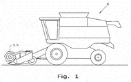
Fig. 1 is a schematical illustration of a vehicle incorporating an embodiment of the electrical motor cooled by the present invention; -
Fig. 2 is a schematical side view of a rotor of the electric motor utilized in the vehicle ofFig. 1 ; -
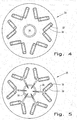
Fig. 3 is a schematical cross sectional view of the rotor ofFig. 2 taken on one end thereof; -
Fig. 4 is a schematical cross sectional view of the rotor ofFig. 2 taken in a mid portion of the rotor; and -
Fig. 5 is another schematical cross sectional view of a portion of the rotor ofFig. 2 taken at the other end of the rotor. - Corresponding reference characters indicate corresponding parts throughout the several views. Referring now to the drawings, and more particularly to
Fig. 1 , there is illustrated avehicle 10, which may be in the form of an agricultural machine, a construction machine, a forestry machine or other vehicle having an electric motor driven assembly 12 including an electrical motor 14. Electrical motor 14 includes arotor 16 as illustrated inFig. 2 . - Now additionally referring to
Figs. 2-5 ,rotor 16 includes a coolantfluid flow path 18 that travels through ashaft 20, a rotor cover orsection 22, through amid section 24, through asecond rotor cover 26 and back throughshaft 20.Rotor section 22 may be a series of laminations or be made of an integral construct having arotor cover 22 in which coolantfluid flow path 18 extends radially outward throughchannels 28 to arrive atslots 30 through which the oil flows pastmagnets 32. When the cooling fluid goes throughmid section 24 ofrotor 16, the laminations may be as shown inFig. 4 wheremagnets 32 are substantially surrounded byslot 30 through which the coolant fluid is flowing. When the cooling fluid reachesend section 26, which may be a lamination or endcap having channels 28,coolant fluid flow 18 passes the fluid back toshaft 20 and it then exits fromrotor assembly 16. - Although, for purposes of clarity,
magnets 32 are illustrated schematically as not touchingslots 30, it is contemplated thatmagnets 32 will be secured to portions ofrotor 16 yet allowing a substantial immersing ofmagnets 32 by the cooling fluid, which is in direct contact withmagnets 32.Fluid path 18 travels essentially along substantial portion of the length ofrotor 16, as shown inFig. 2 .Fluid flow path 18 may be parallel, or substantially parallel, withrotary axis 34 and is radially directed at rotor covers 22 and 26.Slots 30 can be considered as having an inner boundary that consists of the outer portion ofmagnets 32. Also,slots 30 may substantially surroundmagnets 32 on all sides so that the coolant fluid can substantially surroundmagnets 32.Slots 30 andmagnets 32 may be arranged in substantially symmetrical fashion as viewed inFigs. 3-5 . A series of laminations may make upmid section 24. Rotor covers 22 and 26 may be substantially similar or may even be identical with the coolingfluid flow path 18 being defined by the pressure applied to the fluid as it is forced throughrotor 16. - Advantageously, the present invention allows for direct contact of the coolant fluid with
magnets 32 inrotor 16. It is also contemplated thatslots 30 andchannels 28 of the present invention can also be applied to other magnetic constructs, such as electromagnets, where the windings may be in direct contact with the cooling fluid of therotor 16. While the fluid flow path has been schematically illustrated as entering the center ofshaft 20, it is also contemplated that the flow path may come in from a side and exit through a side ofshaft 20.
Claims (11)
- An electric motor for use in a vehicle, the electric motor comprising a rotor having a plurality of magnets; and a plurality of slots in said rotor including a first slot associated with a corresponding one of said plurality of magnets defining a first magnet, said first slot having a boundary that is partially defined by said first magnet, said first slot containing a fluid in direct contact with said first magnet.
- The electric motor of claim 1, wherein the fluid in said first slot moves along a fluid path in said rotor, said rotor having a length, said fluid path being substantially the length of said rotor.
- The electric motor of claim 2, wherein said rotor has a rotational axis, said fluid path that travels along the length of said rotor being substantially parallel with said rotational axis.
- The electric motor of claim 3, wherein said rotor further includes a shaft; a plurality of laminations connected to said shaft, said plurality of slots being contained in said laminations; a first channel in at least one lamination that allows the fluid to pass from said shaft to said first slot; and a second channel in at least one other lamination that allows the fluid to pass from said first slot to said shaft.
- The electric motor of claim 4, wherein the fluid path in the rotor is a path starting in one end of said shaft and then passing sequentially through said first channel, through said first slot, through said second channel, then through an other end of said shaft.
- The electric motor of claim 4, wherein said first channel and said second channel both extend in a substantially radial direction relative to the rotational axis.
- The electric motor of claim 1, wherein said first slot substantially surrounds said first magnet with said first magnet defining an inner boundary of said first slot.
- The electric motor of claim 7, wherein said plurality of magnets and plurality of slots in said rotor are arranged in a substantially symmetrical manner when viewed perpendicular to said rotational axis.
- The electric motor of claim 8, wherein said rotor of said electric motor further comprises a shaft; a plurality of laminations connected to said shaft, said plurality of slots being contained in said laminations; a plurality of first channels in at least one lamination that allows the fluid to pass from said shaft to a corresponding one of said plurality of slots; and a plurality of second channels in at least one other lamination that allows the fluid to pass from said plurality of slots to said shaft.
- The electric motor of claim 9, wherein said plurality of first channels in said at least one lamination define a first rotor cover, and said plurality of second channels in said at least one other lamination define a second rotor cover, said first rotor cover and said second rotor cover being substantially the same.
- A vehicular device, comprising a driven device; and an electric motor according to one of the preceding claims coupled to and driving said driven device.
Applications Claiming Priority (1)
| Application Number | Priority Date | Filing Date | Title |
|---|---|---|---|
| US13/116,237 US20120299403A1 (en) | 2011-05-26 | 2011-05-26 | Method and apparatus for cooling an electrical motor rotor |
Publications (1)
| Publication Number | Publication Date |
|---|---|
| EP2528197A2 true EP2528197A2 (en) | 2012-11-28 |
Family
ID=46084834
Family Applications (1)
| Application Number | Title | Priority Date | Filing Date |
|---|---|---|---|
| EP12166033A Withdrawn EP2528197A2 (en) | 2011-05-26 | 2012-04-27 | Method and apparatus for cooling an electric motor rotor |
Country Status (2)
| Country | Link |
|---|---|
| US (1) | US20120299403A1 (en) |
| EP (1) | EP2528197A2 (en) |
Cited By (3)
| Publication number | Priority date | Publication date | Assignee | Title |
|---|---|---|---|---|
| EP3068021A4 (en) * | 2013-12-13 | 2017-07-19 | Mitsubishi Electric Corporation | Embedded permanent magnet-type rotating electrical machine |
| EP3379696A1 (en) * | 2017-03-21 | 2018-09-26 | Siemens Aktiengesellschaft | Synchronous reluctance machine |
| US10461604B2 (en) | 2014-06-04 | 2019-10-29 | Thyssenkrupp Presta Teccenter Ag | Oil distribution element |
Families Citing this family (10)
| Publication number | Priority date | Publication date | Assignee | Title |
|---|---|---|---|---|
| EP3047151A4 (en) | 2013-09-16 | 2017-05-03 | Altigreen Propulsion Labs Private Limited | A motor-generator shaft with centrifugal fan blades |
| AU2014322794B2 (en) | 2013-09-17 | 2018-10-11 | Altigreen Propulsion Labs Private Limited | An electric or hybrid vehicle using motor-generator having shaft with centrifugal fan blades for cooling |
| JP6855978B2 (en) * | 2017-08-21 | 2021-04-07 | 株式会社Ihi | Permanent magnet synchronous power generation equipment and power generation equipment |
| DE102020110168A1 (en) * | 2020-04-14 | 2021-10-14 | Schaeffler Technologies AG & Co. KG | Rotary electric machine rotor and rotary electric machine |
| US11545860B2 (en) | 2021-02-22 | 2023-01-03 | GM Global Technology Operations LLC | Inserts for motor rotor core |
| US11873826B2 (en) | 2021-02-26 | 2024-01-16 | Deere & Company | Cooling arrangement for electric machines |
| US11770039B2 (en) * | 2021-03-15 | 2023-09-26 | GM Global Technology Operations LLC | Rotor cooling with heat conductive material |
| US11646620B2 (en) | 2021-04-14 | 2023-05-09 | GM Global Technology Operations LLC | Preloading magnets in a rotor core |
| US11777348B2 (en) | 2021-08-03 | 2023-10-03 | GM Global Technology Operations LLC | Rotor core with load bearing polymer and insert |
| US20240235328A1 (en) * | 2023-01-09 | 2024-07-11 | GM Global Technology Operations LLC | Cooling for electric motors |
Citations (3)
| Publication number | Priority date | Publication date | Assignee | Title |
|---|---|---|---|---|
| US5283488A (en) | 1993-02-22 | 1994-02-01 | The United States Of America As Represented By The Secretary Of The Air Force | Rotor cooling structure |
| US20090015081A1 (en) | 2007-07-13 | 2009-01-15 | Aisin Aw Co., Ltd. | Cooling structure and cooling method of rotating electrical machine |
| US7705503B2 (en) | 2005-09-07 | 2010-04-27 | Kabushiki Kaisha Toshiba | Rotating electrical machine |
Family Cites Families (1)
| Publication number | Priority date | Publication date | Assignee | Title |
|---|---|---|---|---|
| WO2007055192A1 (en) * | 2005-11-09 | 2007-05-18 | Kabushiki Kaisha Toshiba | Rotor for electric rotating machine and electric rotating machine |
-
2011
- 2011-05-26 US US13/116,237 patent/US20120299403A1/en not_active Abandoned
-
2012
- 2012-04-27 EP EP12166033A patent/EP2528197A2/en not_active Withdrawn
Patent Citations (3)
| Publication number | Priority date | Publication date | Assignee | Title |
|---|---|---|---|---|
| US5283488A (en) | 1993-02-22 | 1994-02-01 | The United States Of America As Represented By The Secretary Of The Air Force | Rotor cooling structure |
| US7705503B2 (en) | 2005-09-07 | 2010-04-27 | Kabushiki Kaisha Toshiba | Rotating electrical machine |
| US20090015081A1 (en) | 2007-07-13 | 2009-01-15 | Aisin Aw Co., Ltd. | Cooling structure and cooling method of rotating electrical machine |
Cited By (6)
| Publication number | Priority date | Publication date | Assignee | Title |
|---|---|---|---|---|
| EP3068021A4 (en) * | 2013-12-13 | 2017-07-19 | Mitsubishi Electric Corporation | Embedded permanent magnet-type rotating electrical machine |
| US10116178B2 (en) | 2013-12-13 | 2018-10-30 | Mitsubishi Electric Corporation | Rotor with embedded permanent magnet having adhesive on one side and cooling channels on the other side |
| US10461604B2 (en) | 2014-06-04 | 2019-10-29 | Thyssenkrupp Presta Teccenter Ag | Oil distribution element |
| EP3379696A1 (en) * | 2017-03-21 | 2018-09-26 | Siemens Aktiengesellschaft | Synchronous reluctance machine |
| WO2018172033A1 (en) * | 2017-03-21 | 2018-09-27 | Siemens Aktiengesellschaft | Synchronous reluctance machine |
| US10903707B2 (en) | 2017-03-21 | 2021-01-26 | Siemens Aktiengesellschaft | Synchronous reluctance machine |
Also Published As
| Publication number | Publication date |
|---|---|
| US20120299403A1 (en) | 2012-11-29 |
Similar Documents
| Publication | Publication Date | Title |
|---|---|---|
| US20120299403A1 (en) | Method and apparatus for cooling an electrical motor rotor | |
| EP2667486B2 (en) | Electric machine rotor cooling method | |
| CN111614207B (en) | Centrifugal fluid-cooled axial flux electric machine | |
| KR101131534B1 (en) | Arrangement and method for cooling an electrical machine | |
| EP2951907B1 (en) | Pole shoe cooling gap for axial motor | |
| US8247933B2 (en) | Methods and apparatus for a permanent magnet machine with a direct liquid cooled stator | |
| CN103155382B (en) | The internal cooling of the stator module in motor | |
| US8803380B2 (en) | Electric machine module cooling system and method | |
| CN103155376B (en) | Coolant channel for motor stator | |
| CN105322674B (en) | generator armature | |
| US8373316B2 (en) | Coolant flow enhancing device for stator coil end turns of fluid cooled electric motor | |
| US9413208B2 (en) | Enhanced cooling of enclosed air cooled high power motors | |
| US20110273040A1 (en) | Electric Machine Cooling System and Method | |
| US8872399B2 (en) | Stator winding assembly and method | |
| US20140125165A1 (en) | Cooling structure of rotary electric machine | |
| EP2747251A1 (en) | Rotating electrical machine for vehicles with liquid cooling | |
| CN111200335A (en) | Temperature control assembly for an electric machine | |
| CN104953767A (en) | Electric machine having rotor cooling assembly | |
| KR20080066800A (en) | Automotive Cooling Fans | |
| KR20130141511A (en) | Coolant channels for electric machine stator | |
| CN111247724A (en) | Electric machine with cooling device comprising partially subdivided channels | |
| EP3840189A1 (en) | Rotor air cooling system | |
| JP2004129407A (en) | Motor cooling structure | |
| EP3046792B1 (en) | An electric or hybrid vehicle using motor-generator having shaft with centrifugal fan blades for cooling | |
| EP2442060B1 (en) | A generator, in particular for a wind turbine |
Legal Events
| Date | Code | Title | Description |
|---|---|---|---|
| PUAI | Public reference made under article 153(3) epc to a published international application that has entered the european phase |
Free format text: ORIGINAL CODE: 0009012 |
|
| AK | Designated contracting states |
Kind code of ref document: A2 Designated state(s): AL AT BE BG CH CY CZ DE DK EE ES FI FR GB GR HR HU IE IS IT LI LT LU LV MC MK MT NL NO PL PT RO RS SE SI SK SM TR |
|
| AX | Request for extension of the european patent |
Extension state: BA ME |
|
| STAA | Information on the status of an ep patent application or granted ep patent |
Free format text: STATUS: THE APPLICATION IS DEEMED TO BE WITHDRAWN |
|
| 18D | Application deemed to be withdrawn |
Effective date: 20141101 |