EP2527953A2 - Storage device carriers for adapting a storage device of a first size to a slot for a storage device of a second size - Google Patents
Storage device carriers for adapting a storage device of a first size to a slot for a storage device of a second size Download PDFInfo
- Publication number
- EP2527953A2 EP2527953A2 EP12165859A EP12165859A EP2527953A2 EP 2527953 A2 EP2527953 A2 EP 2527953A2 EP 12165859 A EP12165859 A EP 12165859A EP 12165859 A EP12165859 A EP 12165859A EP 2527953 A2 EP2527953 A2 EP 2527953A2
- Authority
- EP
- European Patent Office
- Prior art keywords
- carrier
- storage device
- protrusion
- slot
- side wall
- Prior art date
- Legal status (The legal status is an assumption and is not a legal conclusion. Google has not performed a legal analysis and makes no representation as to the accuracy of the status listed.)
- Withdrawn
Links
Images


Classifications
-
- H—ELECTRICITY
- H05—ELECTRIC TECHNIQUES NOT OTHERWISE PROVIDED FOR
- H05K—PRINTED CIRCUITS; CASINGS OR CONSTRUCTIONAL DETAILS OF ELECTRIC APPARATUS; MANUFACTURE OF ASSEMBLAGES OF ELECTRICAL COMPONENTS
- H05K5/00—Casings, cabinets or drawers for electric apparatus
- H05K5/02—Details
- H05K5/0217—Mechanical details of casings
- H05K5/023—Handles; Grips
-
- G—PHYSICS
- G11—INFORMATION STORAGE
- G11B—INFORMATION STORAGE BASED ON RELATIVE MOVEMENT BETWEEN RECORD CARRIER AND TRANSDUCER
- G11B23/00—Record carriers not specific to the method of recording or reproducing; Accessories, e.g. containers, specially adapted for co-operation with the recording or reproducing apparatus ; Intermediate mediums; Apparatus or processes specially adapted for their manufacture
- G11B23/02—Containers; Storing means both adapted to cooperate with the recording or reproducing means
-
- G—PHYSICS
- G06—COMPUTING OR CALCULATING; COUNTING
- G06F—ELECTRIC DIGITAL DATA PROCESSING
- G06F1/00—Details not covered by groups G06F3/00 - G06F13/00 and G06F21/00
- G06F1/16—Constructional details or arrangements
- G06F1/18—Packaging or power distribution
- G06F1/183—Internal mounting support structures, e.g. for supporting printed circuit boards
-
- G—PHYSICS
- G06—COMPUTING OR CALCULATING; COUNTING
- G06F—ELECTRIC DIGITAL DATA PROCESSING
- G06F1/00—Details not covered by groups G06F3/00 - G06F13/00 and G06F21/00
- G06F1/16—Constructional details or arrangements
- G06F1/18—Packaging or power distribution
- G06F1/183—Internal mounting support structures, e.g. for supporting printed circuit boards
- G06F1/187—Mounting of fixed or removable disk drives
-
- G—PHYSICS
- G11—INFORMATION STORAGE
- G11B—INFORMATION STORAGE BASED ON RELATIVE MOVEMENT BETWEEN RECORD CARRIER AND TRANSDUCER
- G11B33/00—Constructional parts, details or accessories not provided for in the other groups of this subclass
- G11B33/02—Cabinets; Cases; Stands; Disposition of apparatus therein or thereon
-
- G—PHYSICS
- G11—INFORMATION STORAGE
- G11B—INFORMATION STORAGE BASED ON RELATIVE MOVEMENT BETWEEN RECORD CARRIER AND TRANSDUCER
- G11B33/00—Constructional parts, details or accessories not provided for in the other groups of this subclass
- G11B33/12—Disposition of constructional parts in the apparatus, e.g. of power supply, of modules
- G11B33/121—Disposition of constructional parts in the apparatus, e.g. of power supply, of modules the apparatus comprising a single recording/reproducing device
- G11B33/123—Mounting arrangements of constructional parts onto a chassis
- G11B33/124—Mounting arrangements of constructional parts onto a chassis of the single recording/reproducing device, e.g. disk drive, onto a chassis
Definitions
- the invention relates generally to storage systems and more specifically relates to carriers for adapting a storage device of a first size to a slot for a storage device of a second size.
- Storage systems may be used to house a large number of storage devices (e.g., magnetic disks, optical drives, solid-state memory, etc.) and communicatively couple those storage devices with a computer system.
- Storage systems may comprise, for example, rack-mounted blades or other high density enclosures that each comprise multiple storage devices.
- Each blade may be stored within the rack, and may be communicatively coupled with the computer system by use of a suitable backplane or cabling structure (e.g., a cable chain).
- the blade itself may be opened to access the storage devices that it houses, and each storage device may be communicatively coupled with the blade via a hardware connection residing, for example, on a printed circuit board of the blade.
- the blade will typically include slots that are sized for a specific type of drive.
- EIA Electronic Industries Alliance
- 2.5 inch form factor storage devices typically exhibit more desirable characteristics such as faster spindle speeds (and therefore faster rates for accessing and retrieving data stored on the device).
- these devices may not be used in conjunction with existing high density enclosures that have been dimensioned for 3.5 inch form factor drives unless they are adapted in some manner to fit into existing slots. Numerous carriers and adapters are known, but it remains cumbersome to screw 2.5 inch form factor drives into 3.5 inch form factor carriers.
- a field engineer may manage hundreds, if not thousands of storage devices on a daily basis. This may involve swapping storage devices between enclosures, removing storage devices, adding storage devices, cleaning or dusting enclosures, and other routine tasks. To this end, a field engineer desires hardware that simplifies the use of the carriers described above during routine maintenance on the storage system.
- the present invention solves the above and other problems, thereby advancing the state of the useful arts, by providing carriers/adapters for adapting a storage device of a first form factor to a slot for a second form factor, wherein the carrier is capable of experiencing elastic deformation in order to receive the storage device, and the carrier further experiences sufficient spring force while deformed that it may return to its original shape to house the storage device.
- the motion of the storage device may be restrained when the carrier returns to its original shape.
- a carrier for a storage device is provided.
- the carrier is adapted to fit the storage device into a slot adapted for a different size of storage device.
- the carrier comprises an opening means for elastically deforming a shape of the carrier from an original shape so that the carrier may receive the storage device.
- the carrier also comprises at least two restraining means for constraining the motion of the storage device within the carrier when the carrier returns to the original shape.
- the carrier comprises a spacing means for aligning the storage device with the slot while the storage device is restrained within the carrier.
- the carrier is adapted to fit the storage device into a slot adapted to receive a different size of storage device.
- the carrier comprises a first and second side wall, a first and second protrusion, and a lateral member.
- the first side wall comprises a first inward surface of the carrier that defines a first plane.
- the first protrusion is for constraining the motion of the storage device at the carrier, is fixedly attached to the first side wall, and projects outward from the first plane towards an inner portion of the carrier.
- the first protrusion is adapted to contact and restrain the motion of the storage device.
- the second side wall comprises a second inward surface of the carrier that defines a second plane substantially parallel with the first plane.
- the second protrusion is for constraining the motion of the storage device at the carrier, is fixedly attached to the second side wall, and projects outward from the second plane towards an inner portion of the carrier.
- the second protrusion is adapted to contact and restrain the motion of the storage device.
- the lateral member comprises a third inward surface of the carrier that defines a third plane substantially orthogonal to the first plane and the second plane, and is fixedly attached to each side wall.
- the lateral member is adapted to experience elastic deformation that increases a distance between the first protrusion and the second protrusion sufficiently to allow for insertion of the storage device into the carrier, wherein when the lateral member is elastically deformed, it experiences spring force sufficient to return the carrier to an original shape that restrains the storage device within the carrier.
- FIG. 1 is a block diagram of an exemplary high density enclosure in accordance with features and aspects hereof.
- FIGS. 2-5 are block diagrams of an exemplary storage device in accordance with features and aspects hereof.
- FIGS. 6-9 are block diagrams of an exemplary storage device carrier for adapting a storage device to a new form factor in accordance with features and aspects hereof.
- FIGS. 10-11 are block diagrams of an exemplary protrusion of a carrier in accordance with features and aspects hereof.
- FIGS. 12-13 are block diagrams of an exemplary receptacle of a storage device in accordance with features and aspects hereof.
- FIGS. 14-17 are block diagrams of an exemplary carrier undergoing elastic deformation to receive a storage device in accordance with features and aspects hereof.
- FIGS. 18-21 are further block diagrams of an exemplary carrier undergoing elastic deformation to receive a storage device in accordance with features and aspects hereof.
- FIG. 22 illustrates a further embodiment wherein a carrier may comprise a Customer Replaceable Unit (CRU) having a form factor matched to slots of a high density enclosure in accordance with features and aspects hereof..
- CRU Customer Replaceable Unit
- the following embodiments address existing issues with adapting a storage device of a first form factor to fit or mount a slot for a second form factor, by providing carriers/adapters that are capable of experiencing elastic deformation in order to receive a storage device, wherein the carriers further experience sufficient spring force while deformed that they may return to their original shape to house the storage device.
- These carriers are substantially tool-less, and are also significantly easier to use than tool-based methods of adapting a storage device to slot for a storage device having a different form factor.
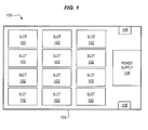
- FIG. 1 is a block diagram of an exemplary high density enclosure 100 in accordance with features and aspects hereof.
- high density enclosure 100 comprises multiple slots 102, each slot adapted to receive a storage device dimensioned according to a defined form factor (e.g., a 3.5 inch form factor).
- High density enclosure 100 may also be referred to as a "blade drive” or “blade enclosure.”
- High density enclosure further comprises a housing structure 104, and optionally includes motors 106 for extending high density enclosure 100 out of a rack.
- High density enclosure 100 may further optionally include a power supply 108 for powering storage devices located at slots 102.
- High density enclosure 100 communicatively couples storage devices of slots 102 so that they may be accessed by a computer system.
- high density enclosure 100 may be dimensioned to enclose a larger or smaller number of storage devices, but will typically be dimensioned to have a size that allows for insertion and removal into a standardized rack-based mounting system.
- rack and enclosure may be defined by EIA standard 310-D.
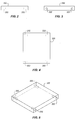
- FIGS. 2-5 are block diagrams of an exemplary storage device 200 in accordance with features and aspects hereof.
- FIG. 2 illustrates a front view
- FIG. 3 illustrates a side view
- FIG. 4 illustrates a top view
- FIG. 5 illustrates a perspective view of storage device 200.
- Storage device 200 has a form factor (e.g., a standard 2.5 inch form factor) that is different than the form factor of the slots for high density enclosure 100 (e.g., a standard 3.5 inch form factor).
- Storage device 200 may comprise any well-known device for storing data in accordance with a known storage technology (e.g., solid state drives, optical drives, magnetic disks, etc.).
- storage device 200 comprises multiple receptacles 202.
- Receptacles 202 may be used for attachment of storage device 200 to a mounting bracket or similar device. Standards defining the dimensions of the form factor of storage device 200 may also define the number, location, and dimensions of receptacles 202.
- receptacles 202 typically comprise four substantially coplanar receptacles, wherein two receptacles are placed at either side of storage device 200.
- receptacles 202 will typically comprise threaded holes intended to receive a screw, bolt, or similar device which may thereby affix storage device 200 to a mounting bracket.
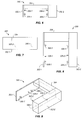
- FIGS. 6-9 are block diagrams of an exemplary storage device carrier 300 for adapting a storage device 200 to a new form factor in accordance with features and aspects hereof.
- FIG. 6 illustrates a front view
- FIG. 7 illustrates a side view
- FIG. 8 illustrates a top view
- FIG. 9 illustrates a perspective view of carrier 300.
- carrier 300 comprises two side walls 302-1 and 302-2, although carrier 300 could comprise a greater number of side walls if desired.
- Each side wall 302 includes an inward surface 308, wherein an inward surface is a portion of a side wall 302 that faces an inner portion of carrier 300.
- inward surface 308-1 of sidewall 302-1 faces an inward portion of carrier 300, as does inward surface 308-2 of sidewall 302-2.
- the inward surfaces 308 of side walls 302 define substantially parallel planes.
- Side walls 302 are fixedly attached to a lateral member 304.
- the inward surface of lateral member 304 is substantially orthogonal to the inward surfaces of side walls 302, and lateral member 304 will typically connect side walls 302 to each other.
- Lateral member 304 may reside, for example, at the top of carrier 300, at the back of carrier 300, or at the front of carrier 300.
- Side walls 302 and lateral member 304 are dimensioned to define a housing structure that fits snugly about the form factor of a storage device (e.g., storage device 200 of FIGS. 2-5 ).
- carrier 300 itself has an exterior dimensioned to snugly fit within the form factor for a slot of a high density enclosure (e.g., slot 102 of enclosure 100 of FIG. 1 ).
- carrier 300 adapts a drive of a smaller form factor to fit a slot for a larger form factor.
- each side wall 302 includes at least one protrusion 306 for fitting into receptacles of the storage device (e.g., receptacles 202 of storage device 200 of FIGS. 2-5 ).
- side wall 302-1 comprises protrusions 306-1 and 306-2
- side wall 302-2 comprises protrusions 306-3 and 306-4.
- protrusions 306 when inserted into receptacles, may fully restrain the rotation and/or motion of a storage device within carrier 300.
- protrusions 306 will typically be aligned with receptacles when they are positioned according to defined standards for the form factor of the storage device.
- carrier 300 may further comprise spacing elements sufficient to match carrier 300 to the dimensions of slots of an enclosure (e.g., spacing elements may comprise deformable pads, rigid structural features of side walls 302, etc.).
- spacing elements may be designed to position the storage device within a slot for communicative coupling with the enclosure. For example, spacing elements may align a SCSI adapter of the storage device with a SCSI adapter of the enclosure.
- a spacing element may be fixedly or removably attached to carrier 300.
- Carrier 300 may be a single molded piece, or may comprise multiple separate elements affixed to each other.
- carrier 300 will comprise a suitable material (e.g., steel, a steel alloy, or other materials capable of experiencing elastic deformation).
- FIGS. 10-11 are block diagrams of an exemplary protrusion 3 06 of a carrier 300 in accordance with features and aspects hereof.
- FIG. 10 illustrates a front view
- FIG. 11 illustrates a side view.
- each protrusion 306 comprises a cylindrical projection from a side wall 302, wherein the cylinder has a diameter D.
- Each cylindrical projection may be adapted for alignment with receptacles of a storage device (e.g., receptacles 202 of storage device 200 of FIGS. 2-5 ) in accordance with form factor standards, such that when the storage device is inserted into a carrier, each protrusion 306 aligns with a receptacle.
- a storage device e.g., receptacles 202 of storage device 200 of FIGS. 2-5
- Each protrusion 306 will typically project substantially orthogonally from a side wall 302. Additionally, protrusions 306 will typically be substantially coplanar with each other, and protrusions 306 from different side walls 302 will typically project in substantially opposite directions (i.e., they will project from opposite side walls towards each other).
- FIGS. 12-13 are block diagrams of an exemplary receptacle 202 of a storage device 200 in accordance with features and aspects hereof.
- FIG. 12 is a front view
- FIG. 13 is a side view.
- Receptacle 202 may comprise any shape, although receptacles 202 will typically comprise threaded holes for receiving a screw, bolt, or similar mechanical device.
- receptacle 202 comprises a threaded hole, it will be appreciated that receptacle 202 has an inner diameter D, corresponding to the inner diameter of the thread.
- Receptacle 202 also has an outer diameter D + ⁇ , corresponding to an outer diameter of the thread. In this figure, ⁇ corresponds to an arbitrary thread depth for receptacle 202.
- receptacles 202 is generally standardized among storage devices having the same form factor.
- protrusions of a carrier may each be aligned and dimensioned to have diameter D corresponding to the inner thread diameter of a receptacle 202 of storage device 200, even before knowing the exact make, model, or product number of storage device 200.
- FIGS. 14-17 are block diagrams of an exemplary carrier 300 undergoing elastic deformation to receive a storage device 200 in accordance with features and aspects hereof.
- carrier 300 is at rest in a default shape.
- lateral member 304 of carrier 300 experiences elastic beam deflection sufficient to allow receptacles 202 of storage device 200 to be inserted or otherwise "slipped" onto protrusions 306 of side wall 302-2.
- lateral member 304 includes an outward surface 304-1, and an inward surface 304-2.
- outward surface 304-1 experiences compression
- inward surface 304-2 experiences extension.
- lateral member 304 While experiencing elastic deflection, lateral member 304 generates a spring force sufficient to return it to its original shape at carrier 300.
- storage device 200 may be inserted onto protrusions 306 of side wall 302-2, as depicted in FIG. 16 .
- lateral member 304 may be released, thereby returning to its original shape and inserting protrusions 306 of side wall 302-1 into receptacles 202 of storage device 200.
- carrier 300 holds storage device 200 when carrier 300 returns to its original shape, as depicted in FIG. 17 .
- a field engineer may quickly adapt a storage device having one form factor to an enclosure having slots of another form factor. Additionally, a field engineer has no need for specialized tools or indeed any tools at all in order to achieve this goal, because the task may be performed by hand.
- FIGS. 18-21 are further block diagrams of an exemplary carrier 300 undergoing elastic deformation to receive a storage device 200 in accordance with features and aspects hereof.
- lateral member 304 comprises two rigid members 701 and 702, and an elastic element 703.
- Rigid members 701 and 702 may be designed to substantially restrain the directions in which elastic element 703 may be deformed by a user.
- rigid members 701 and 702 may be attached to each other via elastic element 703.
- Elastic element 703 may comprise, for example, a coiled spring, a curvilinear spring, an elastomer, or other known materials and designs capable of generating a restorative spring force. As depicted in FIG.
- elastic element 703 experiences minimal or no deflection in a resting state and has a length of L, but when side walls 302 are pulled apart from each other as in FIG. 19 , elastic element 703 experiences elastic deformation sufficient to increase the length of elastic element 703 to L + ⁇ .
- ⁇ corresponds to an arbitrary distance. While the length of elastic element 703 remains L + ⁇ , protrusions 306 of side wall 302-2 may be inserted into receptacles 202 of storage device 200, as depicted in FIG. 20 .
- elastic element 703 experiences spring force sufficient to return it to a length less than L + ⁇ , thereby inserting protrusions 306 of side wall 302-1 into receptacles 202 of storage device 200 and fully restraining the motion and/or rotation of storage device 200, as depicted in FIG. 21 .
- elastic element 703 returns to length L while carrier 300 holds storage device 200.
- elastic element 703 returns to a length greater than L, but less than L + ⁇ . In such embodiments, elastic element 703 continues to apply spring force that pulls protrusions 306 of carrier 300 into receptacles 202 of storage device 200.
- FIG. 22 illustrates a further embodiment wherein a carrier 300 comprises a Customer Replaceable Unit (CRU) 800 having a form factor matched to slots of an enclosure (e.g., slots 102 of enclosure 100 of FIG. 1 ) in accordance with features and aspects hereof.
- CRU 800 may comprise an external housing and a handle 810 for holding CRU 800 and inserting CRU 800 into a slot of an enclosure.
- the CRU may include an external housing having sidewalls 802-1 and 802-2, and also lateral member 804. It will be appreciated that, depending upon how CRU 800 aligns storage device 200, storage device 200 may imbalance CRU 800, making the body of CRU 800 rotate, and thereby pinching handle 810 of CRU 800 against fingers that may grip handle 810. This is generally undesirable.
- handle 810 may include a mechanical stop (e.g., an embossment or catch) to prevent full rotation of the body of CRU 800.
- the weight of CRU 800 or the position of the rotational axis of handle 810 may be altered in order to balance the body of CRU 800.
- the body of CRU 800 may include a "finger hole" or slot for an operator to push the CRU body into a balanced position while CRU 800 is being carried at the handle.
Landscapes
- Engineering & Computer Science (AREA)
- Theoretical Computer Science (AREA)
- General Physics & Mathematics (AREA)
- Human Computer Interaction (AREA)
- Physics & Mathematics (AREA)
- General Engineering & Computer Science (AREA)
- Power Engineering (AREA)
- Computer Hardware Design (AREA)
- Microelectronics & Electronic Packaging (AREA)
- Casings For Electric Apparatus (AREA)
- Packaging Frangible Articles (AREA)
- Packaging Of Annular Or Rod-Shaped Articles, Wearing Apparel, Cassettes, Or The Like (AREA)
- Pile Receivers (AREA)
Abstract
Description
- The invention relates generally to storage systems and more specifically relates to carriers for adapting a storage device of a first size to a slot for a storage device of a second size.
- Storage systems may be used to house a large number of storage devices (e.g., magnetic disks, optical drives, solid-state memory, etc.) and communicatively couple those storage devices with a computer system. Storage systems may comprise, for example, rack-mounted blades or other high density enclosures that each comprise multiple storage devices. Each blade may be stored within the rack, and may be communicatively coupled with the computer system by use of a suitable backplane or cabling structure (e.g., a cable chain). The blade itself may be opened to access the storage devices that it houses, and each storage device may be communicatively coupled with the blade via a hardware connection residing, for example, on a printed circuit board of the blade. To restrain the motion of each storage device within the blade, the blade will typically include slots that are sized for a specific type of drive. For example, it has been generally popular for blades to include slots for standard 3.5 inch form factor hard disks (i.e., the slots are sized to house devices with dimensions according to the 3.5 inch standard defined by the Electronic Industries Alliance (EIA)).
- As technology has progressed, it has become desirable for storage systems to utilize smaller standard 2.5 inch form factor hard disks (i.e., the slots are sized to house devices with dimensions according to the 2.5 inch standard defined by the EIA). In addition to allowing a higher density of drives for a blade, 2.5 inch form factor storage devices typically exhibit more desirable characteristics such as faster spindle speeds (and therefore faster rates for accessing and retrieving data stored on the device). Unfortunately, these devices may not be used in conjunction with existing high density enclosures that have been dimensioned for 3.5 inch form factor drives unless they are adapted in some manner to fit into existing slots. Numerous carriers and adapters are known, but it remains cumbersome to screw 2.5 inch form factor drives into 3.5 inch form factor carriers.
- As a further consideration, in storage environments, a field engineer may manage hundreds, if not thousands of storage devices on a daily basis. This may involve swapping storage devices between enclosures, removing storage devices, adding storage devices, cleaning or dusting enclosures, and other routine tasks. To this end, a field engineer desires hardware that simplifies the use of the carriers described above during routine maintenance on the storage system.
- Thus it is an ongoing challenge to adapt standard 2.5 inch form factor drives to enclosures having slots dimensioned for a standard 3.5 inch form factor in a manner that is cost-efficient, simple, and easy to use.
- The present invention solves the above and other problems, thereby advancing the state of the useful arts, by providing carriers/adapters for adapting a storage device of a first form factor to a slot for a second form factor, wherein the carrier is capable of experiencing elastic deformation in order to receive the storage device, and the carrier further experiences sufficient spring force while deformed that it may return to its original shape to house the storage device. Thus, the motion of the storage device may be restrained when the carrier returns to its original shape. These systems provide further advantages in that they are substantially tool-less (i.e., they do not require screwdrivers or other hand tools to mount the drive within the carrier) and thus are easier to use than tool-based methods of mounting (i.e., the storage device may be "snapped in," as opposed to being screwed into a mounting device with four separate screws).
- In one aspect hereof, a carrier for a storage device is provided. The carrier is adapted to fit the storage device into a slot adapted for a different size of storage device. The carrier comprises an opening means for elastically deforming a shape of the carrier from an original shape so that the carrier may receive the storage device. The carrier also comprises at least two restraining means for constraining the motion of the storage device within the carrier when the carrier returns to the original shape. Furthermore, the carrier comprises a spacing means for aligning the storage device with the slot while the storage device is restrained within the carrier.
- Another aspect hereof provides another carrier for a storage device. The carrier is adapted to fit the storage device into a slot adapted to receive a different size of storage device. The carrier comprises a first and second side wall, a first and second protrusion, and a lateral member. The first side wall comprises a first inward surface of the carrier that defines a first plane. The first protrusion is for constraining the motion of the storage device at the carrier, is fixedly attached to the first side wall, and projects outward from the first plane towards an inner portion of the carrier. The first protrusion is adapted to contact and restrain the motion of the storage device. The second side wall comprises a second inward surface of the carrier that defines a second plane substantially parallel with the first plane. The second protrusion is for constraining the motion of the storage device at the carrier, is fixedly attached to the second side wall, and projects outward from the second plane towards an inner portion of the carrier. The second protrusion is adapted to contact and restrain the motion of the storage device. The lateral member comprises a third inward surface of the carrier that defines a third plane substantially orthogonal to the first plane and the second plane, and is fixedly attached to each side wall. The lateral member is adapted to experience elastic deformation that increases a distance between the first protrusion and the second protrusion sufficiently to allow for insertion of the storage device into the carrier, wherein when the lateral member is elastically deformed, it experiences spring force sufficient to return the carrier to an original shape that restrains the storage device within the carrier.
-
FIG. 1 is a block diagram of an exemplary high density enclosure in accordance with features and aspects hereof. -
FIGS. 2-5 are block diagrams of an exemplary storage device in accordance with features and aspects hereof. -
FIGS. 6-9 are block diagrams of an exemplary storage device carrier for adapting a storage device to a new form factor in accordance with features and aspects hereof. -
FIGS. 10-11 are block diagrams of an exemplary protrusion of a carrier in accordance with features and aspects hereof. -
FIGS. 12-13 are block diagrams of an exemplary receptacle of a storage device in accordance with features and aspects hereof. -
FIGS. 14-17 are block diagrams of an exemplary carrier undergoing elastic deformation to receive a storage device in accordance with features and aspects hereof. -
FIGS. 18-21 are further block diagrams of an exemplary carrier undergoing elastic deformation to receive a storage device in accordance with features and aspects hereof. -
FIG. 22 illustrates a further embodiment wherein a carrier may comprise a Customer Replaceable Unit (CRU) having a form factor matched to slots of a high density enclosure in accordance with features and aspects hereof.. - The following embodiments address existing issues with adapting a storage device of a first form factor to fit or mount a slot for a second form factor, by providing carriers/adapters that are capable of experiencing elastic deformation in order to receive a storage device, wherein the carriers further experience sufficient spring force while deformed that they may return to their original shape to house the storage device. These carriers are substantially tool-less, and are also significantly easier to use than tool-based methods of adapting a storage device to slot for a storage device having a different form factor.
-
FIG. 1 is a block diagram of an exemplaryhigh density enclosure 100 in accordance with features and aspects hereof. In this embodiment,high density enclosure 100 comprisesmultiple slots 102, each slot adapted to receive a storage device dimensioned according to a defined form factor (e.g., a 3.5 inch form factor).High density enclosure 100 may also be referred to as a "blade drive" or "blade enclosure." High density enclosure further comprises ahousing structure 104, and optionally includesmotors 106 for extendinghigh density enclosure 100 out of a rack.High density enclosure 100 may further optionally include apower supply 108 for powering storage devices located atslots 102.High density enclosure 100 communicatively couples storage devices ofslots 102 so that they may be accessed by a computer system. - One of ordinary skill in the art will appreciate that
high density enclosure 100 may be dimensioned to enclose a larger or smaller number of storage devices, but will typically be dimensioned to have a size that allows for insertion and removal into a standardized rack-based mounting system. Furthermore, it will be appreciated that countless different embodiments of similar or dissimilar drive enclosures/blades may be provided, andhigh density enclosure 100 is but one exemplary embodiment of such an enclosure. For example, the rack and enclosure may be defined by EIA standard 310-D. -
FIGS. 2-5 are block diagrams of anexemplary storage device 200 in accordance with features and aspects hereof.FIG. 2 illustrates a front view,FIG. 3 illustrates a side view,FIG. 4 illustrates a top view, andFIG. 5 illustrates a perspective view ofstorage device 200.Storage device 200 has a form factor (e.g., a standard 2.5 inch form factor) that is different than the form factor of the slots for high density enclosure 100 (e.g., a standard 3.5 inch form factor).Storage device 200 may comprise any well-known device for storing data in accordance with a known storage technology (e.g., solid state drives, optical drives, magnetic disks, etc.). In this embodiment,storage device 200 comprisesmultiple receptacles 202.Receptacles 202 may be used for attachment ofstorage device 200 to a mounting bracket or similar device. Standards defining the dimensions of the form factor ofstorage device 200 may also define the number, location, and dimensions ofreceptacles 202. For example,receptacles 202 typically comprise four substantially coplanar receptacles, wherein two receptacles are placed at either side ofstorage device 200. Furthermore,receptacles 202 will typically comprise threaded holes intended to receive a screw, bolt, or similar device which may thereby affixstorage device 200 to a mounting bracket. -
FIGS. 6-9 are block diagrams of an exemplarystorage device carrier 300 for adapting astorage device 200 to a new form factor in accordance with features and aspects hereof..FIG. 6 illustrates a front view,FIG. 7 illustrates a side view,FIG. 8 illustrates a top view, andFIG. 9 illustrates a perspective view ofcarrier 300. In this embodiment,carrier 300 comprises two side walls 302-1 and 302-2, althoughcarrier 300 could comprise a greater number of side walls if desired. Eachside wall 302 includes an inward surface 308, wherein an inward surface is a portion of aside wall 302 that faces an inner portion ofcarrier 300. For example, inward surface 308-1 of sidewall 302-1 faces an inward portion ofcarrier 300, as does inward surface 308-2 of sidewall 302-2. The inward surfaces 308 ofside walls 302 define substantially parallel planes. -
Side walls 302 are fixedly attached to alateral member 304. The inward surface oflateral member 304 is substantially orthogonal to the inward surfaces ofside walls 302, andlateral member 304 will typically connectside walls 302 to each other.Lateral member 304 may reside, for example, at the top ofcarrier 300, at the back ofcarrier 300, or at the front ofcarrier 300.Side walls 302 andlateral member 304 are dimensioned to define a housing structure that fits snugly about the form factor of a storage device (e.g.,storage device 200 ofFIGS. 2-5 ). Furthermore,carrier 300 itself has an exterior dimensioned to snugly fit within the form factor for a slot of a high density enclosure (e.g., slot 102 ofenclosure 100 ofFIG. 1 ). Thus,carrier 300 adapts a drive of a smaller form factor to fit a slot for a larger form factor. - To ensure that the motion of a storage device is adequately restrained while the storage device is within
carrier 300, eachside wall 302 includes at least oneprotrusion 306 for fitting into receptacles of the storage device (e.g.,receptacles 202 ofstorage device 200 ofFIGS. 2-5 ). In one embodiment, side wall 302-1 comprises protrusions 306-1 and 306-2, while side wall 302-2 comprises protrusions 306-3 and 306-4. One of ordinary skill in the art will appreciate thatprotrusions 306, when inserted into receptacles, may fully restrain the rotation and/or motion of a storage device withincarrier 300. Furthermore,protrusions 306 will typically be aligned with receptacles when they are positioned according to defined standards for the form factor of the storage device. - In order to properly adapt a storage device to a slot of a high density enclosure, the widths, heights, and depths of
side walls 302 atcarrier 300 may vary significantly. In order to reduce usage of material,side walls 302 need not be solid structures, but may be partly or completely hollow. In addition toside walls 302,carrier 300 may further comprise spacing elements sufficient to matchcarrier 300 to the dimensions of slots of an enclosure (e.g., spacing elements may comprise deformable pads, rigid structural features ofside walls 302, etc.). Furthermore, spacing elements may be designed to position the storage device within a slot for communicative coupling with the enclosure. For example, spacing elements may align a SCSI adapter of the storage device with a SCSI adapter of the enclosure. A spacing element may be fixedly or removably attached tocarrier 300. -
Carrier 300 may be a single molded piece, or may comprise multiple separate elements affixed to each other. Preferably,carrier 300 will comprise a suitable material (e.g., steel, a steel alloy, or other materials capable of experiencing elastic deformation). -
FIGS. 10-11 are block diagrams of an exemplary protrusion 3 06 of acarrier 300 in accordance with features and aspects hereof..FIG. 10 illustrates a front view andFIG. 11 illustrates a side view. In this embodiment, eachprotrusion 306 comprises a cylindrical projection from aside wall 302, wherein the cylinder has a diameter D. Each cylindrical projection may be adapted for alignment with receptacles of a storage device (e.g.,receptacles 202 ofstorage device 200 ofFIGS. 2-5 ) in accordance with form factor standards, such that when the storage device is inserted into a carrier, eachprotrusion 306 aligns with a receptacle. Eachprotrusion 306 will typically project substantially orthogonally from aside wall 302. Additionally,protrusions 306 will typically be substantially coplanar with each other, andprotrusions 306 fromdifferent side walls 302 will typically project in substantially opposite directions (i.e., they will project from opposite side walls towards each other). -
FIGS. 12-13 are block diagrams of anexemplary receptacle 202 of astorage device 200 in accordance with features and aspects hereof.FIG. 12 is a front view, andFIG. 13 is a side view.Receptacle 202 may comprise any shape, althoughreceptacles 202 will typically comprise threaded holes for receiving a screw, bolt, or similar mechanical device. Whenreceptacle 202 comprises a threaded hole, it will be appreciated thatreceptacle 202 has an inner diameter D, corresponding to the inner diameter of the thread.Receptacle 202 also has an outer diameter D+Δ, corresponding to an outer diameter of the thread. In this figure, Δ corresponds to an arbitrary thread depth forreceptacle 202. It will be appreciated that the size and location ofreceptacles 202 is generally standardized among storage devices having the same form factor. Thus, protrusions of a carrier may each be aligned and dimensioned to have diameter D corresponding to the inner thread diameter of areceptacle 202 ofstorage device 200, even before knowing the exact make, model, or product number ofstorage device 200. -
FIGS. 14-17 are block diagrams of anexemplary carrier 300 undergoing elastic deformation to receive astorage device 200 in accordance with features and aspects hereof. InFIG. 14 ,carrier 300 is at rest in a default shape. However, inFIG. 15 ,lateral member 304 ofcarrier 300 experiences elastic beam deflection sufficient to allowreceptacles 202 ofstorage device 200 to be inserted or otherwise "slipped" ontoprotrusions 306 of side wall 302-2. It will be appreciated thatlateral member 304 includes an outward surface 304-1, and an inward surface 304-2. During elastic beam deflection oflateral member 304, outward surface 304-1 experiences compression, while inward surface 304-2 experiences extension. While experiencing elastic deflection,lateral member 304 generates a spring force sufficient to return it to its original shape atcarrier 300. Withcarrier 300 now in a new shape,storage device 200 may be inserted ontoprotrusions 306 of side wall 302-2, as depicted inFIG. 16 . Oncestorage device 200 has been inserted ontoprotrusions 306 of side wall 302-2,lateral member 304 may be released, thereby returning to its original shape and insertingprotrusions 306 of side wall 302-1 intoreceptacles 202 ofstorage device 200. Thus,carrier 300 holdsstorage device 200 whencarrier 300 returns to its original shape, as depicted inFIG. 17 . Utilizing such an insertion mechanism, a field engineer may quickly adapt a storage device having one form factor to an enclosure having slots of another form factor. Additionally, a field engineer has no need for specialized tools or indeed any tools at all in order to achieve this goal, because the task may be performed by hand. -
FIGS. 18-21 are further block diagrams of anexemplary carrier 300 undergoing elastic deformation to receive astorage device 200 in accordance with features and aspects hereof. In this embodiment,lateral member 304 comprises tworigid members elastic element 703.Rigid members elastic element 703 may be deformed by a user. Further,rigid members elastic element 703.Elastic element 703 may comprise, for example, a coiled spring, a curvilinear spring, an elastomer, or other known materials and designs capable of generating a restorative spring force. As depicted inFIG. 18 ,elastic element 703 experiences minimal or no deflection in a resting state and has a length of L, but whenside walls 302 are pulled apart from each other as inFIG. 19 ,elastic element 703 experiences elastic deformation sufficient to increase the length ofelastic element 703 to L+Δ. In this figure, Δ corresponds to an arbitrary distance. While the length ofelastic element 703 remains L+Δ,protrusions 306 of side wall 302-2 may be inserted intoreceptacles 202 ofstorage device 200, as depicted inFIG. 20 . Then, by releasing one ofside walls 302,elastic element 703 experiences spring force sufficient to return it to a length less than L+Δ, thereby insertingprotrusions 306 of side wall 302-1 intoreceptacles 202 ofstorage device 200 and fully restraining the motion and/or rotation ofstorage device 200, as depicted inFIG. 21 . In one embodiment,elastic element 703 returns to length L whilecarrier 300 holdsstorage device 200. In other embodiments,elastic element 703 returns to a length greater than L, but less than L+Δ. In such embodiments,elastic element 703 continues to apply spring force that pullsprotrusions 306 ofcarrier 300 intoreceptacles 202 ofstorage device 200. -
FIG. 22 illustrates a further embodiment wherein acarrier 300 comprises a Customer Replaceable Unit (CRU) 800 having a form factor matched to slots of an enclosure (e.g.,slots 102 ofenclosure 100 ofFIG. 1 ) in accordance with features and aspects hereof.CRU 800 may comprise an external housing and ahandle 810 for holdingCRU 800 and insertingCRU 800 into a slot of an enclosure. For example, the CRU may include an external housing having sidewalls 802-1 and 802-2, and alsolateral member 804. It will be appreciated that, depending upon howCRU 800 alignsstorage device 200,storage device 200may imbalance CRU 800, making the body ofCRU 800 rotate, and thereby pinchinghandle 810 ofCRU 800 against fingers that may grip handle 810. This is generally undesirable. To address this issue, numerous solutions may be used. For example, handle 810 may include a mechanical stop (e.g., an embossment or catch) to prevent full rotation of the body ofCRU 800. In another example, the weight ofCRU 800 or the position of the rotational axis ofhandle 810 may be altered in order to balance the body ofCRU 800. In a still further embodiment, the body ofCRU 800 may include a "finger hole" or slot for an operator to push the CRU body into a balanced position whileCRU 800 is being carried at the handle. - While the invention has been illustrated and described in the drawings and foregoing description, such illustration and description is to be considered as exemplary and not restrictive in character. One embodiment of the invention and minor variants thereof have been shown and described. Protection is desired for all changes and modifications that come within the spirit of the invention. Those skilled in the art will appreciate variations of the above-described embodiments that fall within the scope of the invention. As a result, the invention is not limited to the specific examples and illustrations discussed above, but only by the following claims and their equivalents.
Claims (15)
- A carrier (300) for a storage device (200), the carrier (300) adapted to fit the storage device (200) into a slot (102) adapted to receive a different size of storage device, the carrier (300) characterized in that the carrier (300) comprises:a first side wall (302-1) comprising a first inward surface (308-1) of the carrier (300) that defines a first plane;a first protrusion (306-1) for constraining the motion of the storage device (200) at the carrier (300), the first protrusion (306-1) fixedly attached to the first side wall (302-1) and projecting outward from the first plane towards an inner portion of the carrier (300), the first protrusion (306-1) adapted to contact and restrain the motion of the storage device (200);a second side wall (302-2) comprising a second inward surface (308-2) of the carrier (300) that defines a second plane substantially parallel with the first plane;a second protrusion (306-3) for constraining the motion of the storage device (200) at the carrier, the second protrusion (306-3) fixedly attached to the second side wall (302-2) and projecting outward from the second plane towards an inner portion of the carrier (300), the second protrusion (306-3) adapted to contact and restrain the motion of the storage device (200); anda lateral member (304) comprising a third inward surface of the carrier that defines a third plane substantially orthogonal to the first plane and the second plane, the lateral member (304) fixedly attached to each side wall (302), the lateral member (304) adapted to experience elastic deformation that increases a distance between the first protrusion (306-1) and the second protrusion (306-3) sufficiently to allow for insertion of the storage device (200) into the carrier (300), wherein when the lateral member (304) is elastically deformed, it experiences spring force sufficient to return the carrier (300) to an original shape that restrains the storage device (200) within the carrier (300).
- The carrier (300) of claim 1,
wherein the first protrusion (306-1) is further adapted to be aligned with a first receptacle (202) of the storage device (200) and inserted into the first receptacle (202), and
wherein the second protrusion (306-3) is further adapted to be aligned with a second receptacle (202) of the storage device (200) and inserted into the second receptacle (202). - The carrier (300) of claim 2,
wherein each protrusion (306) comprises a cylinder having a diameter not greater than an inner diameter of each receptacle (202), and wherein a cylinder length of each protrusion (306) is not greater than a depth of each receptacle (202). - The carrier (300) of claim 1,
wherein the elastic deformation of the lateral member (304) comprises deflection. - The carrier (300) of claim 1,
wherein the elastic deformation of the lateral member (304) comprises extension. - The carrier (300) of claim 1,
wherein the carrier (300) comprises a Customer Replaceable Unit (800), CRU (800), the CRU (800) comprising:a handle (810) for carrying the CRU (800) and inserting the CRU (800) into the slot (102),wherein the handle (810) is connected for rotational movement with respect to each side wall (302). - The carrier (300) of claim 6,
wherein the first side wall (302-1), the second side wall (302-2), and the lateral member (304) are adapted to align the storage device (200) with the slot (102) when the storage device (200) is restrained within the carrier (300). - The carrier (300) of claim 1,
wherein the storage device (200) is a 2.5 inch form factor storage device, and the slot (102) is adapted to receive a 3.5 inch form factor storage device. - A carrier (300) for a storage device (200), the carrier (300) adapted to fit the storage device (200) into a slot (102) adapted for a different size of storage device, the carrier (300) characterized in that the carrier (300) comprises:an opening means (304) for elastically deforming a shape of the carrier (300) from an original shape so that the carrier (300) may receive the storage device (200);at least two restraining means (306) for constraining the motion of the storage device (200) within the carrier (300) when the carrier (300) returns to the original shape; anda spacing means (302) for aligning the storage device (200) with the slot (102) while the storage device (200) is restrained within the carrier (300).
- The carrier (300) of claim 9,
wherein the at least two restraining means (306) are adapted to be aligned with receptacles (202) of the storage device (200) and are further adapted to be inserted into the receptacles (202). - The carrier (300) of claim 10,
wherein each restraining means (306) comprises a length of protrusion not greater than a depth of each receptacle (202). - The carrier (300) of claim 9,
wherein first restraining means (306-1) and the second restraining means (306-3) are substantially coplanar. - The carrier (300) of claim 9,
wherein the elastic deformation of the opening means (304) comprises deflection. - The carrier (300) of claim 9,
wherein the elastic deformation of the opening means (304) comprises extension. - The carrier of claim 9,
wherein the storage device (200) is a 2.5 inch form factor storage device, and the slot (102) is adapted to receive a 3.5 inch form factor storage device.
Applications Claiming Priority (1)
| Application Number | Priority Date | Filing Date | Title |
|---|---|---|---|
| US13/116,818 US8644017B2 (en) | 2011-05-26 | 2011-05-26 | Storage device carriers for adapting a storage device of a first size to a slot for a storage device of a second size |
Publications (2)
| Publication Number | Publication Date |
|---|---|
| EP2527953A2 true EP2527953A2 (en) | 2012-11-28 |
| EP2527953A3 EP2527953A3 (en) | 2014-05-28 |
Family
ID=46178395
Family Applications (1)
| Application Number | Title | Priority Date | Filing Date |
|---|---|---|---|
| EP12165859.5A Withdrawn EP2527953A3 (en) | 2011-05-26 | 2012-04-27 | Storage device carriers for adapting a storage device of a first size to a slot for a storage device of a second size |
Country Status (6)
| Country | Link |
|---|---|
| US (2) | US8644017B2 (en) |
| EP (1) | EP2527953A3 (en) |
| JP (1) | JP5274629B2 (en) |
| KR (1) | KR101454065B1 (en) |
| CN (1) | CN102802376B (en) |
| TW (1) | TWI472286B (en) |
Families Citing this family (19)
| Publication number | Priority date | Publication date | Assignee | Title |
|---|---|---|---|---|
| TWI441986B (en) * | 2011-03-25 | 2014-06-21 | Wistron Corp | Fixing mechanism for fixing a component |
| US8644017B2 (en) * | 2011-05-26 | 2014-02-04 | Lsi Corporation | Storage device carriers for adapting a storage device of a first size to a slot for a storage device of a second size |
| US9326415B2 (en) * | 2013-09-14 | 2016-04-26 | Seagate Technology Llc | Chassis for storage devices |
| US9232677B2 (en) * | 2013-09-14 | 2016-01-05 | Seagate Technology Llc | Chassis for storage devices |
| TWI481338B (en) * | 2013-11-05 | 2015-04-11 | Quanta Comp Inc | Hard disk assembly |
| JP6264137B2 (en) * | 2014-03-25 | 2018-01-24 | 富士通株式会社 | Electronic equipment and mounting members |
| US9632545B2 (en) * | 2014-03-29 | 2017-04-25 | Lenovo (Singapore) Pte. Ltd. | Drive tray |
| WO2016018345A1 (en) * | 2014-07-31 | 2016-02-04 | Hewlett-Packard Development Company, L.P. | Next generation form factor (ngff) carrier |
| TWI526144B (en) * | 2014-09-04 | 2016-03-11 | 緯創資通股份有限公司 | Installation mechanism for replaceable device and electronic apparatus therewith |
| US9281015B1 (en) | 2014-12-14 | 2016-03-08 | Aic Inc. | Storage media conversion device and server using the same |
| TWI575516B (en) * | 2015-01-23 | 2017-03-21 | 勤誠興業股份有限公司 | Holding structure for storage device |
| US20160217097A1 (en) | 2015-01-26 | 2016-07-28 | Hewlett-Packard Development Company, L.P. | Storage device carrier assembly |
| US9763353B1 (en) * | 2015-03-23 | 2017-09-12 | Amazon Technologies, Inc. | Mass storage device retainer assembly |
| US9648775B2 (en) * | 2015-07-17 | 2017-05-09 | Super Micro Computer, Inc | Tool-less storage device adaptor tray with spring mechanism |
| US10074403B2 (en) * | 2015-07-17 | 2018-09-11 | Super Micro Computer, Inc. | Tool-less storage device adaptor tray with slider mechanism |
| US10546616B2 (en) * | 2018-01-30 | 2020-01-28 | Quanta Computer Inc. | Adjustable storage device carrier |
| CN112462867B (en) * | 2019-09-06 | 2022-09-02 | 英业达科技有限公司 | Case with detachable bracket |
| TWI718682B (en) * | 2019-09-25 | 2021-02-11 | 仁寶電腦工業股份有限公司 | Rotary extending frame |
| US20230054055A1 (en) * | 2022-09-22 | 2023-02-23 | Intel Corporation | Mounting adaptor assemblies to support memory devices in server systems |
Citations (1)
| Publication number | Priority date | Publication date | Assignee | Title |
|---|---|---|---|---|
| DE10007418A1 (en) * | 2000-02-18 | 2001-09-06 | Fujitsu Siemens Computers Gmbh | Withdrawable tray frame structure for hard disc drive, has side sections equipped with inwardly directed pins for gripping into openings in the hard disc drive and tray assembly |
Family Cites Families (31)
| Publication number | Priority date | Publication date | Assignee | Title |
|---|---|---|---|---|
| US5277615A (en) | 1992-09-24 | 1994-01-11 | Compaq Computer Corporation | Apparatus for removably supporting a plurality of hot plug-connected hard disk drives |
| US5319519A (en) | 1992-11-20 | 1994-06-07 | Summatec Computer Corporation | Housing with latch and ejection mechanism air portable hard disk drive |
| DE69533487T2 (en) * | 1994-11-29 | 2005-09-22 | Intel Corp., Santa Clara | PORTABLE DISK DRIVE AND FRAME FRAME |
| FR2739280B1 (en) | 1995-09-29 | 1997-11-07 | Oreal | COSMETIC COMPOSITION COMPRISING AT LEAST ONE GRAFT SILICONE POLYMER AND AT LEAST ONE POLYSILOXANE-POLYOXYALKYLENE BLOCK COPOLYMER |
| US5682291A (en) * | 1996-07-10 | 1997-10-28 | Dell U.S.A., L.P. | Carrier for a computer device |
| DE69619374T2 (en) * | 1996-10-03 | 2002-08-29 | Hewlett-Packard Co. (N.D.Ges.D.Staates Delaware), Palo Alto | Assembly arrangement for the attachment of one of two different sized system sub-units |
| JPH11195282A (en) | 1997-11-07 | 1999-07-21 | Hitachi Ltd | Magnetic disk drive and magnetic disk drive system |
| KR19990028691U (en) * | 1997-12-27 | 1999-07-15 | 구자홍 | Hard disk drive mounting structure of computer |
| US6608564B2 (en) | 2000-01-25 | 2003-08-19 | Hewlett-Packard Development Company, L.P. | Removable memory cartridge system for use with a server or other processor-based device |
| CN2447827Y (en) * | 2000-10-19 | 2001-09-12 | 环隆电气股份有限公司 | Slide-on computer rack mount |
| US6487081B2 (en) * | 2000-12-29 | 2002-11-26 | Compaq Information Technologies Group, L.P. | Hard disk drive mounting system and method |
| US6535381B2 (en) | 2001-03-22 | 2003-03-18 | Intel Corporation | Hot swap drawer assembly |
| US6999306B2 (en) | 2003-08-21 | 2006-02-14 | Hewlett-Packard Development Company, L.P. | Method and system and apparatus for storing data storage devices |
| JP3920256B2 (en) | 2003-10-02 | 2007-05-30 | 日本航空電子工業株式会社 | Card connector |
| US7145770B1 (en) | 2003-10-08 | 2006-12-05 | Copan Systems, Inc. | Method and apparatus of packaging disk drives in a data storage system |
| TWM272357U (en) | 2005-02-02 | 2005-08-01 | Wistron Corp | Hard disk fixing module |
| JP4621039B2 (en) | 2005-02-22 | 2011-01-26 | 株式会社日立製作所 | Disk unit |
| FR2886808B1 (en) | 2005-06-07 | 2007-07-20 | Alstom Transport Sa | ELECTRONIC CARD DEVICE COMPRISING A CHEST AND A DRAWER WITH ELECTRONIC CARDS PROVIDED FOR INSERTING IN THE COFFEE |
| US7453707B2 (en) | 2005-07-28 | 2008-11-18 | Dell Products L.P. | Tool-less, translating hard drive bay |
| WO2007126239A1 (en) * | 2006-04-28 | 2007-11-08 | Zalman Tech Co., Ltd. | Hard disk drive bracket |
| US7460365B2 (en) | 2006-10-02 | 2008-12-02 | Dell Products L.P. | Interposer for a drive bay |
| JP2008108405A (en) | 2006-10-27 | 2008-05-08 | Victor Co Of Japan Ltd | Adapter for mounting hard disk drive cartridge |
| JP3131595U (en) | 2007-02-23 | 2007-05-17 | 鋭▲あん▼科技股▲ふん▼有限公司 | 3.5-inch disk array module with built-in 2.5-inch hard disk |
| TWI349505B (en) | 2007-08-27 | 2011-09-21 | Ibm | Hard disk drive conversion enclosure |
| US7944687B2 (en) | 2007-10-05 | 2011-05-17 | Jabil Circuit, Inc. | Storage device carrier |
| US7864539B2 (en) | 2008-04-11 | 2011-01-04 | Lsi Corporation | Horizontal drive drawer system and method |
| US7715182B2 (en) | 2008-07-03 | 2010-05-11 | Lsi Corporation | Drive box |
| US20100217909A1 (en) | 2009-02-24 | 2010-08-26 | Sun Microsystems, Inc. | Field replaceable unit for solid state drive system |
| JP2011005452A (en) | 2009-06-29 | 2011-01-13 | Osamu Matsumoto | Fluid mixing apparatus |
| JP5574269B2 (en) * | 2009-09-03 | 2014-08-20 | 日本電気株式会社 | Hard disk drive mounter |
| US8644017B2 (en) * | 2011-05-26 | 2014-02-04 | Lsi Corporation | Storage device carriers for adapting a storage device of a first size to a slot for a storage device of a second size |
-
2011
- 2011-05-26 US US13/116,818 patent/US8644017B2/en not_active Expired - Fee Related
- 2011-07-19 TW TW100125524A patent/TWI472286B/en not_active IP Right Cessation
- 2011-08-02 KR KR1020110077079A patent/KR101454065B1/en not_active Expired - Fee Related
- 2011-08-04 JP JP2011170788A patent/JP5274629B2/en not_active Expired - Fee Related
- 2011-08-09 CN CN201110226141.1A patent/CN102802376B/en not_active Expired - Fee Related
-
2012
- 2012-04-27 EP EP12165859.5A patent/EP2527953A3/en not_active Withdrawn
-
2013
- 2013-11-12 US US14/077,611 patent/US8854805B2/en not_active Expired - Fee Related
Patent Citations (1)
| Publication number | Priority date | Publication date | Assignee | Title |
|---|---|---|---|---|
| DE10007418A1 (en) * | 2000-02-18 | 2001-09-06 | Fujitsu Siemens Computers Gmbh | Withdrawable tray frame structure for hard disc drive, has side sections equipped with inwardly directed pins for gripping into openings in the hard disc drive and tray assembly |
Also Published As
| Publication number | Publication date |
|---|---|
| US8854805B2 (en) | 2014-10-07 |
| KR101454065B1 (en) | 2014-10-27 |
| US20120299453A1 (en) | 2012-11-29 |
| CN102802376B (en) | 2016-02-24 |
| EP2527953A3 (en) | 2014-05-28 |
| US20140070682A1 (en) | 2014-03-13 |
| KR20120132270A (en) | 2012-12-05 |
| TW201249291A (en) | 2012-12-01 |
| CN102802376A (en) | 2012-11-28 |
| US8644017B2 (en) | 2014-02-04 |
| JP2012248176A (en) | 2012-12-13 |
| JP5274629B2 (en) | 2013-08-28 |
| TWI472286B (en) | 2015-02-01 |
Similar Documents
| Publication | Publication Date | Title |
|---|---|---|
| US8644017B2 (en) | Storage device carriers for adapting a storage device of a first size to a slot for a storage device of a second size | |
| US7019965B2 (en) | Ejector mechanism and a carrier including same | |
| US9609778B1 (en) | Server having a latch | |
| US7930812B2 (en) | Toolless rack mounting rail installation latch | |
| US8373983B2 (en) | Server | |
| US7782603B2 (en) | Tool-less electronic component retention | |
| US8331085B2 (en) | Electronic device | |
| US10595443B2 (en) | Open-ended screwless positioning module of access apparatus | |
| US8582286B2 (en) | Removable storage system for server bay | |
| TW201030499A (en) | Computer including hot-pluggable disk storage drives that are mounted in an in-line arrangement | |
| US9466954B1 (en) | Rack mountable power distribution units | |
| US8339781B2 (en) | Electronic device and rail module | |
| US8174824B2 (en) | Enclosure with access panel | |
| US20070047194A1 (en) | Computer system with vertically offset hard disk drives | |
| US20230301013A1 (en) | Electronic device and power distribution module | |
| RU158402U1 (en) | ADAPTER FOR MEDIA | |
| US10910019B2 (en) | Retractable guide features for data storage device carriers | |
| US20210345507A1 (en) | Expansion card holder and hook fixing mechanism | |
| CN120712788A (en) | Equipment locking device | |
| CN104516443B (en) | Drawing out type loading attachment | |
| US9508392B2 (en) | Systems and methods for mechanical isolation of information handling resources | |
| CN111522409B (en) | Blade server case | |
| WO2007126239A1 (en) | Hard disk drive bracket | |
| CN213677760U (en) | Electric automation control stores box with thermal control part | |
| US20220346261A1 (en) | Computing unit for a hpc cabinet and a method for accessing an electronic component of the computing unit |
Legal Events
| Date | Code | Title | Description |
|---|---|---|---|
| PUAI | Public reference made under article 153(3) epc to a published international application that has entered the european phase |
Free format text: ORIGINAL CODE: 0009012 |
|
| AK | Designated contracting states |
Kind code of ref document: A2 Designated state(s): AL AT BE BG CH CY CZ DE DK EE ES FI FR GB GR HR HU IE IS IT LI LT LU LV MC MK MT NL NO PL PT RO RS SE SI SK SM TR |
|
| AX | Request for extension of the european patent |
Extension state: BA ME |
|
| PUAL | Search report despatched |
Free format text: ORIGINAL CODE: 0009013 |
|
| AK | Designated contracting states |
Kind code of ref document: A3 Designated state(s): AL AT BE BG CH CY CZ DE DK EE ES FI FR GB GR HR HU IE IS IT LI LT LU LV MC MK MT NL NO PL PT RO RS SE SI SK SM TR |
|
| AX | Request for extension of the european patent |
Extension state: BA ME |
|
| RIC1 | Information provided on ipc code assigned before grant |
Ipc: G06F 1/18 20060101AFI20140422BHEP Ipc: G11B 33/12 20060101ALI20140422BHEP |
|
| 17P | Request for examination filed |
Effective date: 20141112 |
|
| RBV | Designated contracting states (corrected) |
Designated state(s): AL AT BE BG CH CY CZ DE DK EE ES FI FR GB GR HR HU IE IS IT LI LT LU LV MC MK MT NL NO PL PT RO RS SE SI SK SM TR |
|
| 17Q | First examination report despatched |
Effective date: 20150210 |
|
| STAA | Information on the status of an ep patent application or granted ep patent |
Free format text: STATUS: THE APPLICATION IS DEEMED TO BE WITHDRAWN |
|
| 18D | Application deemed to be withdrawn |
Effective date: 20150623 |