EP2527950A2 - Knob and cooking appliance - Google Patents
Knob and cooking appliance Download PDFInfo
- Publication number
- EP2527950A2 EP2527950A2 EP12169192A EP12169192A EP2527950A2 EP 2527950 A2 EP2527950 A2 EP 2527950A2 EP 12169192 A EP12169192 A EP 12169192A EP 12169192 A EP12169192 A EP 12169192A EP 2527950 A2 EP2527950 A2 EP 2527950A2
- Authority
- EP
- European Patent Office
- Prior art keywords
- shaft lever
- shell
- accommodating portion
- lever accommodating
- knob
- Prior art date
- Legal status (The legal status is an assumption and is not a legal conclusion. Google has not performed a legal analysis and makes no representation as to the accuracy of the status listed.)
- Granted
Links
Images


Classifications
-
- G—PHYSICS
- G05—CONTROLLING; REGULATING
- G05G—CONTROL DEVICES OR SYSTEMS INSOFAR AS CHARACTERISED BY MECHANICAL FEATURES ONLY
- G05G1/00—Controlling members, e.g. knobs or handles; Assemblies or arrangements thereof; Indicating position of controlling members
- G05G1/08—Controlling members for hand actuation by rotary movement, e.g. hand wheels
- G05G1/10—Details, e.g. of discs, knobs, wheels or handles
Definitions
- the present invention relates to the field of cooking appliances, and in particular, to a knob used in a cooking appliance.
- An existing knob is generally manufactured integrally. Therefore, the whole knob is manufactured by adopting the same material. In this way, a problem is caused. If a material suitable for electroplating is adopted to obtain a better appearance effect, the knob is easily fractured. However, if a high-strength material is adopted to avoid fracturing, a new disadvantage is caused that the electroplating cannot be performed to obtain the better appearance effect. It is thus clear that how to take into account both the appearance and the strength of the material is always a technical problem urgently to be solved in this field.
- the present invention puts forward a knob and a cooking appliance provided with the knob.
- the knob put forward by the present invention includes a shell and a shaft lever accommodating portion.
- the shaft lever accommodating portion is provided with a shaft hole adapting to an end portion of a shaft lever, and the shell and the shaft lever accommodating portion are separately manufactured. In this way, it is possible that the shell and the shaft lever accommodating portion are manufactured by adopting different materials, and thereby, both the appearance and the strength of the knob may be taken into account.
- a main body of the shaft lever accommodating portion is provided in the shell.
- the shell is manufactured by adopting a material suitable for electroplating. In this way, the beauty of the appearance of the knob may be guaranteed.
- the shell is manufactured by adopting an ABS plastic material or a mixed material of ABS and PC.
- the shaft lever accommodating portion is manufactured by adopting a nylon material or a metal material or a PBT material.
- the strength of the knob may be guaranteed, thereby reducing the occurrence of fracturing in use and increasing the service life of the knob.
- the shell and the shaft lever accommodating portion are fixed together in a hot riveting manner.
- the efficiency of fixing the shell and the shaft lever accommodating portion may be improved, and the cost may also be saved.
- the shell is provided with at least one hollow cylindrical plastic protrusion;
- the shaft lever accommodating portion is provided with a through hole for the cylindrical plastic protrusion to pass through; and the cylindrical plastic protrusion is used to be hot riveted after passing through the corresponding through hole, so as to fix the shell and the shaft lever accommodating portion together.
- the efficiency of fixing the shell and the shaft lever accommodating portion may be improved, and the cost may also be saved.
- the number of the cylindrical plastic protrusion is 2 or 3 or 4 or 5.
- the shaft lever accommodating portion includes a supporting portion, and an outer edge of the supporting portion fits an inner wall of the shell. In this way, it helps to improve the fixed effect between the shell and the shaft lever accommodating portion.
- the supporting portion is provided with at least one gap; the inner wall of the shell is provided with a protruding portion corresponding to the gap; and when the shell and the shaft lever accommodating portion are fixed together, the protruding portion is retained in the gap.
- the protruding portion is retained in the gap.
- the shell is provided with at least one hollow cylindrical plastic protrusion; the supporting portion is provided with a through hole for the cylindrical plastic protrusion to pass through; and the cylindrical plastic protrusion is used to be hot riveted after passing through the corresponding through hole, so as to fix the shell and the shaft lever accommodating portion together.
- the efficiency of fixing the shell and the shaft lever accommodating portion may be improved, and the cost may also be saved.
- the shaft lever accommodating portion is provided with a protruding portion or a gap;
- the shell is provided with a gap corresponding to the protruding portion on the shaft lever accommodating portion, or a protruding portion corresponding to the gap on the shaft lever accommodating portion; and when the shell and the shaft lever accommodating portion are fixed together, the protruding portion is retained in the corresponding gap.
- it not only helps to improve the fixed effect between the shell and the shaft lever accommodating portion, but also functions to limit a position, that is, it is convenient to determine the specific position where the shaft lever accommodating portion is retained in the shell, thereby improving the assembly efficiency.
- the present invention also puts forward a cooking appliance, which includes a valve body and a knob as described above.
- the valve body includes a shaft lever, and the knob is retained on the shaft lever.
- the present invention puts forward a knob embodiment, as shown in FIGs. 1 to 12 .
- the knob embodiment includes a shell 1 and a shaft lever accommodating portion 2.
- the shaft accommodating portion 2 is provided with a shaft hole 4 adapting to an end portion of a shaft lever 3.
- the shell 1 and the shaft lever accommodating portion 2 are separately manufactured, and are then assembled together.
- the shell 1 is integrally formed.
- the shaft lever accommodating portion 2 is also integrally formed.
- a main body of the shaft lever accommodating portion 2 is provided in the shell 1.
- the "main body” is used for limitation because the part of the shaft hole 4 of the shaft lever accommodating portion 2 extends out of the cavity enclosed by the shell 1.
- the shell 1 is manufactured by adopting a material suitable for electroplating, such as a mixed material of ABS and PC.
- the ABS is an abbreviation for acrylonitrile butadiene styrene plastic.
- the PC is an abbreviation for polycarbonate, which is a colorless and transparent amorphous thermoplastic material.
- the shaft lever accommodating portion 2 is manufactured by adopting a nylon material or a metal material or a PBT material.
- the PBT is an abbreviation for polybutylene terephthalate.
- the shell 1 and the shaft lever accommodating portion 2 are fixed together in a hot riveting manner.
- the shell 1 is provided with four hollow cylindrical plastic protrusions 5.
- the shaft lever accommodating portion 2 includes a supporting portion 7, and the supporting portion 7 is provided with four through holes 6 for the four cylindrical plastic protrusions 5 to pass through.
- Each of the cylindrical plastic protrusions 5 is used to be hot riveted after passing through the corresponding through hole 6, so as to fix the shell 1 and the shaft lever accommodating portion 2 together.
- Each of the cylindrical plastic protrusions 5 adopts a hollow structure to facilitate performing a fusion welding operation on the cylindrical plastic protrusion 5, thereby accomplishing the hot riveting.
- FIGs. 9 to 11 The fixed effect of the shell 1 and the shaft lever accommodating portion 2 is shown in FIGs. 9 to 11 , where an outer edge of the supporting portion 7 fits an inner wall of the shell 1.
- the whole supporting portion 7 is in a round structure.
- the shell 1 includes an opening, a bottom wall and a circle of sidewall provided along the edge of the bottom wall, and the shaft lever accommodating portion 2 enters the shell 1 through the opening.
- the inner wall of the shell 1 facing the opening is provided with four protruding portions 9a, and the four protruding portions 9a are arranged in a "cross" shape.
- the shaft lever accommodating portion 2 is provided with four gaps 8a one-to-one corresponding to the four protruding portions 9a.
- the bottom wall of the shell 1 is provided with a gap 8b.
- the gap 8b is essentially a round through hole 6.
- the shaft lever accommodating portion 2 is provided with a protruding portion 9b corresponding to the gap 8b.
- the protruding portion 9b is retained in the corresponding gap 8b.
- the setting of the protruding portion 9b and the gap 8b not only helps to improve the fixed effect between the shell 1 and the shaft lever accommodating portion 2, but also functions to limit a position, and may also mark the knob, so as to conveniently determine a rotation position in use.
- the supporting portion 7 is provided with four gaps 8c.
- the inner wall of the shell 1 is provided with four protruding portions (not shown) respectively corresponding to the four gaps 8c.
- the four protruding portions are respectively retained in the corresponding gaps 8c.
- the setting of the protruding portions and the gaps 8c helps to improve the fixed effect between the shell 1 and the shaft lever accommodating portion 2.
- the number of the cylindrical plastic protrusion may also be 1 or 2 or 3 or 5 or 6 or more.
- the cylindrical plastic protrusions may also be arranged asymmetrically.
- a reinforcing rib may also be provided on the shell.
- the present invention also puts forward a cooking appliance, which is provided with a valve body and the above knob embodiment.
- the valve body includes a shaft lever and the knob is retained on the shaft lever.
- the cooking appliance may be a gas stove, an induction cooker, or a stove combining a gas stove and an induction cooker. It should be noted that, the understanding of the gas stove in the present invention should be broadened to include any stove provided with a burner, the type of gas source of which is not limited and may be natural gas, artificial coal gas, liquefied petroleum gas, biogas and any other gas source that may be similarly applied.
Landscapes
- Physics & Mathematics (AREA)
- General Physics & Mathematics (AREA)
- Engineering & Computer Science (AREA)
- Automation & Control Theory (AREA)
- Cookers (AREA)
- Mechanical Control Devices (AREA)
- Laminated Bodies (AREA)
Abstract
Description
- The present invention relates to the field of cooking appliances, and in particular, to a knob used in a cooking appliance.
- An existing knob is generally manufactured integrally. Therefore, the whole knob is manufactured by adopting the same material. In this way, a problem is caused. If a material suitable for electroplating is adopted to obtain a better appearance effect, the knob is easily fractured. However, if a high-strength material is adopted to avoid fracturing, a new disadvantage is caused that the electroplating cannot be performed to obtain the better appearance effect. It is thus clear that how to take into account both the appearance and the strength of the material is always a technical problem urgently to be solved in this field.
- Unless supported by sufficient evidences, the prior art described herein does not mean that it is known to those of ordinary skill in the art before the filing date of this application.
- To solve the above technical problem, the present invention puts forward a knob and a cooking appliance provided with the knob.
- The knob put forward by the present invention includes a shell and a shaft lever accommodating portion. The shaft lever accommodating portion is provided with a shaft hole adapting to an end portion of a shaft lever, and the shell and the shaft lever accommodating portion are separately manufactured. In this way, it is possible that the shell and the shaft lever accommodating portion are manufactured by adopting different materials, and thereby, both the appearance and the strength of the knob may be taken into account.
- Optionally, a main body of the shaft lever accommodating portion is provided in the shell.
- Optionally, the shell is manufactured by adopting a material suitable for electroplating. In this way, the beauty of the appearance of the knob may be guaranteed.
- Optionally, the shell is manufactured by adopting an ABS plastic material or a mixed material of ABS and PC.
- Optionally, the shaft lever accommodating portion is manufactured by adopting a nylon material or a metal material or a PBT material. In this way, the strength of the knob may be guaranteed, thereby reducing the occurrence of fracturing in use and increasing the service life of the knob.
- Optionally, the shell and the shaft lever accommodating portion are fixed together in a hot riveting manner. In this way, the efficiency of fixing the shell and the shaft lever accommodating portion may be improved, and the cost may also be saved.
- Optionally, the shell is provided with at least one hollow cylindrical plastic protrusion; the shaft lever accommodating portion is provided with a through hole for the cylindrical plastic protrusion to pass through; and the cylindrical plastic protrusion is used to be hot riveted after passing through the corresponding through hole, so as to fix the shell and the shaft lever accommodating portion together. In this way, the efficiency of fixing the shell and the shaft lever accommodating portion may be improved, and the cost may also be saved.
- Optionally, the number of the cylindrical plastic protrusion is 2 or 3 or 4 or 5.
- Optionally, the shaft lever accommodating portion includes a supporting portion, and an outer edge of the supporting portion fits an inner wall of the shell. In this way, it helps to improve the fixed effect between the shell and the shaft lever accommodating portion.
- Optionally, the supporting portion is provided with at least one gap; the inner wall of the shell is provided with a protruding portion corresponding to the gap; and when the shell and the shaft lever accommodating portion are fixed together, the protruding portion is retained in the gap. In this way, it not only helps to improve the fixed effect between the shell and the shaft lever accommodating portion, but also functions to limit a position, that is, it is convenient to determine the specific position where the shaft lever accommodating portion is retained in the shell, thereby improving the assembly efficiency.
- Optionally, the shell is provided with at least one hollow cylindrical plastic protrusion; the supporting portion is provided with a through hole for the cylindrical plastic protrusion to pass through; and the cylindrical plastic protrusion is used to be hot riveted after passing through the corresponding through hole, so as to fix the shell and the shaft lever accommodating portion together. In this way, the efficiency of fixing the shell and the shaft lever accommodating portion may be improved, and the cost may also be saved.
- Optionally, the shaft lever accommodating portion is provided with a protruding portion or a gap; the shell is provided with a gap corresponding to the protruding portion on the shaft lever accommodating portion, or a protruding portion corresponding to the gap on the shaft lever accommodating portion; and when the shell and the shaft lever accommodating portion are fixed together, the protruding portion is retained in the corresponding gap. In this way, it not only helps to improve the fixed effect between the shell and the shaft lever accommodating portion, but also functions to limit a position, that is, it is convenient to determine the specific position where the shaft lever accommodating portion is retained in the shell, thereby improving the assembly efficiency.
- The present invention also puts forward a cooking appliance, which includes a valve body and a knob as described above. The valve body includes a shaft lever, and the knob is retained on the shaft lever.
- The following accompanying drawings are merely provided for schematically illustrating and explaining the present invention, but not intended to limit the scope of the present invention, where:
-
FIG. 1 is a schematic structural diagram of a shell of a knob embodiment according to the present invention; -
FIG. 2 is another schematic structural diagram of a shell of a knob embodiment according to the present invention; -
FIG. 3 is a sectional view along Line A-A inFIG. 2 ; -
FIG. 4 is a sectional view along Line B-B inFIG. 2 ; -
FIG. 5 is another schematic structural diagram of a shell of a knob embodiment according to the present invention; -
FIG. 6 is a schematic structural diagram of a shaft lever accommodating portion of a knob embodiment according to the present invention; -
FIG. 7 is another schematic structural diagram of a shaft lever accommodating portion of a knob embodiment according to the present invention; -
FIG. 8 is another schematic structural diagram of a shaft lever accommodating portion of a knob embodiment according to the present invention; -
FIG. 9 is a schematic structural diagram of a knob embodiment according to the present invention; -
FIG. 10 is a sectional view along Line A-A inFIG. 9 ; -
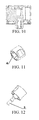
FIG. 11 is another schematic structural diagram of a knob embodiment according to the present invention; and -
FIG. 12 is a schematic diagram of a joining relation between a shaft lever and a knob embodiment according to the present invention. - 1-Shell; 2-Shaft lever accommodating portion; 3-Shaft lever; 4-Shaft hole; 5-Cylindrical plastic protusion; 6-Through hole; 7-Supporting portion; 8a, 8b, 8c-Gap; 9a, 9b-Protruding portion.
- To make the objective, solutions and beneficial effects of the present invention more clearly, the present invention is further illustrated with reference to the accompanying drawings and exemplary embodiments.
- The present invention puts forward a knob embodiment, as shown in
FIGs. 1 to 12 . The knob embodiment includes ashell 1 and a shaftlever accommodating portion 2. The shaft accommodatingportion 2 is provided with ashaft hole 4 adapting to an end portion of ashaft lever 3. Theshell 1 and the shaftlever accommodating portion 2 are separately manufactured, and are then assembled together. Theshell 1 is integrally formed. The shaftlever accommodating portion 2 is also integrally formed. A main body of the shaftlever accommodating portion 2 is provided in theshell 1. The "main body" is used for limitation because the part of theshaft hole 4 of the shaftlever accommodating portion 2 extends out of the cavity enclosed by theshell 1. Theshell 1 is manufactured by adopting a material suitable for electroplating, such as a mixed material of ABS and PC. The ABS is an abbreviation for acrylonitrile butadiene styrene plastic. The PC is an abbreviation for polycarbonate, which is a colorless and transparent amorphous thermoplastic material. The shaftlever accommodating portion 2 is manufactured by adopting a nylon material or a metal material or a PBT material. The PBT is an abbreviation for polybutylene terephthalate. - The
shell 1 and the shaftlever accommodating portion 2 are fixed together in a hot riveting manner. As shown inFIGs. 1 to 4 , theshell 1 is provided with four hollow cylindricalplastic protrusions 5. As shown inFIGs. 6 to 8 , the shaftlever accommodating portion 2 includes a supportingportion 7, and the supportingportion 7 is provided with four throughholes 6 for the four cylindricalplastic protrusions 5 to pass through. Each of the cylindricalplastic protrusions 5 is used to be hot riveted after passing through the corresponding throughhole 6, so as to fix theshell 1 and the shaftlever accommodating portion 2 together. Each of the cylindricalplastic protrusions 5 adopts a hollow structure to facilitate performing a fusion welding operation on the cylindricalplastic protrusion 5, thereby accomplishing the hot riveting. The fixed effect of theshell 1 and the shaftlever accommodating portion 2 is shown inFIGs. 9 to 11 , where an outer edge of the supportingportion 7 fits an inner wall of theshell 1. The whole supportingportion 7 is in a round structure. Theshell 1 includes an opening, a bottom wall and a circle of sidewall provided along the edge of the bottom wall, and the shaftlever accommodating portion 2 enters theshell 1 through the opening. - As shown in
FIGs. 1 and 2 , the inner wall of theshell 1 facing the opening is provided with four protrudingportions 9a, and the four protrudingportions 9a are arranged in a "cross" shape. As shown inFIGs. 7 and 8 , the shaftlever accommodating portion 2 is provided with fourgaps 8a one-to-one corresponding to the four protrudingportions 9a. When theshell 1 and the shaftlever accommodating portion 2 are fixed together, the protrudingportions 9a are retained in thecorresponding gaps 8a. The setting of the protrudingportions 9a and thegaps 8a helps to improve the fixed effect between theshell 1 and the shaftlever accommodating portion 2. - As shown in
FIGs. 2 and5 , the bottom wall of theshell 1 is provided with agap 8b. Thegap 8b is essentially a round throughhole 6. As shown inFIGs. 8 and 9 , the shaftlever accommodating portion 2 is provided with a protrudingportion 9b corresponding to thegap 8b. When theshell 1 and the shaftlever accommodating portion 2 are fixed together, the protrudingportion 9b is retained in thecorresponding gap 8b. The setting of the protrudingportion 9b and thegap 8b not only helps to improve the fixed effect between theshell 1 and the shaftlever accommodating portion 2, but also functions to limit a position, and may also mark the knob, so as to conveniently determine a rotation position in use. - As shown in
FIGs. 6 to 8 , the supportingportion 7 is provided with fourgaps 8c. The inner wall of theshell 1 is provided with four protruding portions (not shown) respectively corresponding to the fourgaps 8c. When theshell 1 and the shaftlever accommodating portion 2 are fixed together, the four protruding portions are respectively retained in the correspondinggaps 8c. The setting of the protruding portions and thegaps 8c helps to improve the fixed effect between theshell 1 and the shaftlever accommodating portion 2. - The above are merely the exemplary embodiments of the present invention, and other embodiments may be obtained by modifying and replacing some technical features. For example, the number of the cylindrical plastic protrusion may also be 1 or 2 or 3 or 5 or 6 or more. For another example, the cylindrical plastic protrusions may also be arranged asymmetrically. For another example, a reinforcing rib may also be provided on the shell.
- The present invention also puts forward a cooking appliance, which is provided with a valve body and the above knob embodiment. The valve body includes a shaft lever and the knob is retained on the shaft lever. The cooking appliance may be a gas stove, an induction cooker, or a stove combining a gas stove and an induction cooker. It should be noted that, the understanding of the gas stove in the present invention should be broadened to include any stove provided with a burner, the type of gas source of which is not limited and may be natural gas, artificial coal gas, liquefied petroleum gas, biogas and any other gas source that may be similarly applied.
- It should be noted that, the present invention is not limited to the above embodiments, but covers all the possible implementations determined according to the claims and the disclosure of the specification. Therefore, any simple modification, equivalent replacement, or improvement made without departing from the spirit and principle of the present invention shall fall within the protection scope of the present invention.
Claims (13)
- A knob, characterized by:comprising a shell and a shaft lever accommodating portion, wherein the shaft lever accommodating portion is provided with a shaft hole adapting to an end portion of a shaft lever, and the shell and the shaft lever accommodating portion are separately manufactured.
- The knob according to claim 1, characterized in that:a main body of the shaft lever accommodating portion is provided in the shell.
- The knob according to claim 1, characterized in that:the shell is manufactured by adopting a material suitable for electroplating.
- The knob according to claim 3, characterized in that:the shell is manufactured by adopting an ABS material or a mixed material of ABS and PC.
- The knob according to claim 1, characterized in that:the shaft lever accommodating portion is manufactured by adopting a nylon material or a metal material or a PBT material.
- The knob according to claim 1, characterized in that:the shell and the shaft lever accommodating portion are fixed together in a hot riveting manner.
- The knob according to any one of claims 1 to 6, characterized in that:the shell is provided with at least one hollow cylindrical plastic protrusion;the shaft lever accommodating portion is provided with a through hole for the cylindrical plastic protrusion to pass through; andthe cylindrical plastic protrusion is used to be hot riveted after passing through the corresponding through hole, so as to fix the shell and the shaft lever accommodating portion together.
- The knob according to claim 7, characterized in that:the number of the cylindrical plastic protrusion is 2 or 3 or 4 or 5.
- The knob according to any one of claims 1 to 6, characterized in that:the shaft lever accommodating portion comprises a supporting portion, and an outer edge of the supporting portion fits an inner wall of the shell.
- The knob according to claim 9, characterized in that:the supporting portion is provided with at least one gap;the inner wall of the shell is provided with a protruding portion corresponding to the gap; andwhen the shell and the shaft lever accommodating portion are fixed together, the protruding portion is retained in the gap.
- The knob according to claim 9, characterized in that:the shell is provided with at least one hollow cylindrical plastic protrusion;the supporting portion is provided with a through hole for the cylindrical plastic protrusion to pass through; andthe cylindrical plastic protrusion is used to be hot riveted after passing through the corresponding through hole, so as to fix the shell and the shaft lever accommodating portion together.
- The knob according to any one of claims 1 to 6, characterized in that:the shaft lever accommodating portion is provided with a protruding portion or a gap;the shell is provided with a gap corresponding to the protruding portion on the shaft lever accommodating portion, or a protruding portion corresponding to the gap on the shaft lever accommodating portion; andwhen the shell and the shaft lever accommodating portion are fixed together, the protruding portion is retained in the corresponding gap.
- A cooking appliance, comprising a valve body and a knob according to any one of the above claims, wherein the valve body comprises a shaft lever, and the knob is retained on the shaft lever.
Applications Claiming Priority (1)
| Application Number | Priority Date | Filing Date | Title |
|---|---|---|---|
| CN201110148623XA CN102799209A (en) | 2011-05-27 | 2011-05-27 | Knob and stove |
Publications (3)
| Publication Number | Publication Date |
|---|---|
| EP2527950A2 true EP2527950A2 (en) | 2012-11-28 |
| EP2527950A3 EP2527950A3 (en) | 2013-07-24 |
| EP2527950B1 EP2527950B1 (en) | 2015-07-08 |
Family
ID=46149257
Family Applications (1)
| Application Number | Title | Priority Date | Filing Date |
|---|---|---|---|
| EP12169192.7A Not-in-force EP2527950B1 (en) | 2011-05-27 | 2012-05-24 | Knob and cooking appliance |
Country Status (3)
| Country | Link |
|---|---|
| EP (1) | EP2527950B1 (en) |
| CN (1) | CN102799209A (en) |
| ES (1) | ES2544081T3 (en) |
Cited By (1)
| Publication number | Priority date | Publication date | Assignee | Title |
|---|---|---|---|---|
| WO2016060631A3 (en) * | 2014-10-14 | 2016-08-11 | Imren Plastik Sanayi Ve Ticaret Limited Sirketi | A button mechanism |
Family Cites Families (7)
| Publication number | Priority date | Publication date | Assignee | Title |
|---|---|---|---|---|
| US2190577A (en) * | 1938-12-01 | 1940-02-13 | Albert H Tinnerman | Connection for knobs and the like |
| GB1130488A (en) * | 1966-05-27 | 1968-10-16 | Carr Fastener Co Ltd | Fastener for securing a knob to the end of a rod |
| US3541882A (en) * | 1968-12-31 | 1970-11-24 | Perkin Elmer Corp | Electrically insulating knobs |
| EP1248177B1 (en) * | 2001-04-05 | 2007-12-05 | Alps Electric Co., Ltd. | Fitting structure for knobs |
| JP2006066288A (en) * | 2004-08-27 | 2006-03-09 | Mitsubishi Electric Corp | Operating mechanism |
| CN101430981A (en) * | 2007-11-06 | 2009-05-13 | 英业达股份有限公司 | Knob structure |
| CN202041875U (en) * | 2011-04-15 | 2011-11-16 | 昆山艾盛塑胶机电有限公司 | Knob |
-
2011
- 2011-05-27 CN CN201110148623XA patent/CN102799209A/en active Pending
-
2012
- 2012-05-24 EP EP12169192.7A patent/EP2527950B1/en not_active Not-in-force
- 2012-05-24 ES ES12169192.7T patent/ES2544081T3/en active Active
Non-Patent Citations (1)
| Title |
|---|
| None |
Cited By (1)
| Publication number | Priority date | Publication date | Assignee | Title |
|---|---|---|---|---|
| WO2016060631A3 (en) * | 2014-10-14 | 2016-08-11 | Imren Plastik Sanayi Ve Ticaret Limited Sirketi | A button mechanism |
Also Published As
| Publication number | Publication date |
|---|---|
| EP2527950B1 (en) | 2015-07-08 |
| EP2527950A3 (en) | 2013-07-24 |
| ES2544081T3 (en) | 2015-08-27 |
| CN102799209A (en) | 2012-11-28 |
Similar Documents
| Publication | Publication Date | Title |
|---|---|---|
| US9146033B2 (en) | Illuminated knobs for an appliance | |
| CN204063153U (en) | Kitchen range and luminous knob assembly thereof | |
| US7961558B2 (en) | Timepiece | |
| EP2527950B1 (en) | Knob and cooking appliance | |
| WO2014101930A1 (en) | Dishwasher with visually improved indication means | |
| EP2039821A1 (en) | Knob assembly for laundry machine and manufacturing method thereof | |
| US10281154B2 (en) | Illuminated knob assembly for an appliance | |
| KR101686668B1 (en) | Dial knob assembly and cooker including the same | |
| EP2541151A1 (en) | High-frequency cooking device | |
| JP6145933B2 (en) | lighting equipment | |
| KR102552742B1 (en) | Door for refrigerator | |
| JP2006302537A (en) | Rotating lamp | |
| CN212591775U (en) | Cup subassembly and cooking machine of cooking machine | |
| JP2020193480A (en) | Water faucet | |
| CN219479746U (en) | Thermos cup with replaceable cup body pattern | |
| CN100580322C (en) | Outer casing of cooking utensil | |
| CN105559616B (en) | A detachable upper cover device and electric rice cooker having the same | |
| CN210007930U (en) | electromagnetic ovens | |
| CN204133237U (en) | Cooking equipment and cover assembly, electric cooker | |
| WO2011070378A9 (en) | Oven door shield | |
| EP3581072A1 (en) | Housing assembly and cooking appliance | |
| KR101144257B1 (en) | Pot lid assembly | |
| GB2488076A (en) | Oven door shield | |
| ES2583148A1 (en) | Cooking field device (Machine-translation by Google Translate, not legally binding) | |
| CN208463641U (en) | Cooking apparatus |
Legal Events
| Date | Code | Title | Description |
|---|---|---|---|
| PUAI | Public reference made under article 153(3) epc to a published international application that has entered the european phase |
Free format text: ORIGINAL CODE: 0009012 |
|
| AK | Designated contracting states |
Kind code of ref document: A2 Designated state(s): AL AT BE BG CH CY CZ DE DK EE ES FI FR GB GR HR HU IE IS IT LI LT LU LV MC MK MT NL NO PL PT RO RS SE SI SK SM TR |
|
| AX | Request for extension of the european patent |
Extension state: BA ME |
|
| PUAL | Search report despatched |
Free format text: ORIGINAL CODE: 0009013 |
|
| AK | Designated contracting states |
Kind code of ref document: A3 Designated state(s): AL AT BE BG CH CY CZ DE DK EE ES FI FR GB GR HR HU IE IS IT LI LT LU LV MC MK MT NL NO PL PT RO RS SE SI SK SM TR |
|
| AX | Request for extension of the european patent |
Extension state: BA ME |
|
| RIC1 | Information provided on ipc code assigned before grant |
Ipc: G05G 1/10 20060101AFI20130614BHEP |
|
| 17P | Request for examination filed |
Effective date: 20140124 |
|
| RBV | Designated contracting states (corrected) |
Designated state(s): AL AT BE BG CH CY CZ DE DK EE ES FI FR GB GR HR HU IE IS IT LI LT LU LV MC MK MT NL NO PL PT RO RS SE SI SK SM TR |
|
| GRAP | Despatch of communication of intention to grant a patent |
Free format text: ORIGINAL CODE: EPIDOSNIGR1 |
|
| INTG | Intention to grant announced |
Effective date: 20150212 |
|
| RAP1 | Party data changed (applicant data changed or rights of an application transferred) |
Owner name: BSH HAUSGERAETE GMBH |
|
| GRAS | Grant fee paid |
Free format text: ORIGINAL CODE: EPIDOSNIGR3 |
|
| GRAA | (expected) grant |
Free format text: ORIGINAL CODE: 0009210 |
|
| AK | Designated contracting states |
Kind code of ref document: B1 Designated state(s): AL AT BE BG CH CY CZ DE DK EE ES FI FR GB GR HR HU IE IS IT LI LT LU LV MC MK MT NL NO PL PT RO RS SE SI SK SM TR |
|
| REG | Reference to a national code |
Ref country code: GB Ref legal event code: FG4D |
|
| REG | Reference to a national code |
Ref country code: AT Ref legal event code: REF Ref document number: 735858 Country of ref document: AT Kind code of ref document: T Effective date: 20150715 Ref country code: CH Ref legal event code: EP |
|
| REG | Reference to a national code |
Ref country code: IE Ref legal event code: FG4D |
|
| REG | Reference to a national code |
Ref country code: DE Ref legal event code: R096 Ref document number: 602012008531 Country of ref document: DE |
|
| REG | Reference to a national code |
Ref country code: ES Ref legal event code: FG2A Ref document number: 2544081 Country of ref document: ES Kind code of ref document: T3 Effective date: 20150827 |
|
| REG | Reference to a national code |
Ref country code: AT Ref legal event code: MK05 Ref document number: 735858 Country of ref document: AT Kind code of ref document: T Effective date: 20150708 |
|
| REG | Reference to a national code |
Ref country code: NL Ref legal event code: MP Effective date: 20150708 |
|
| REG | Reference to a national code |
Ref country code: LT Ref legal event code: MG4D |
|
| PG25 | Lapsed in a contracting state [announced via postgrant information from national office to epo] |
Ref country code: NO Free format text: LAPSE BECAUSE OF FAILURE TO SUBMIT A TRANSLATION OF THE DESCRIPTION OR TO PAY THE FEE WITHIN THE PRESCRIBED TIME-LIMIT Effective date: 20151008 Ref country code: FI Free format text: LAPSE BECAUSE OF FAILURE TO SUBMIT A TRANSLATION OF THE DESCRIPTION OR TO PAY THE FEE WITHIN THE PRESCRIBED TIME-LIMIT Effective date: 20150708 Ref country code: LT Free format text: LAPSE BECAUSE OF FAILURE TO SUBMIT A TRANSLATION OF THE DESCRIPTION OR TO PAY THE FEE WITHIN THE PRESCRIBED TIME-LIMIT Effective date: 20150708 Ref country code: LV Free format text: LAPSE BECAUSE OF FAILURE TO SUBMIT A TRANSLATION OF THE DESCRIPTION OR TO PAY THE FEE WITHIN THE PRESCRIBED TIME-LIMIT Effective date: 20150708 |
|
| PG25 | Lapsed in a contracting state [announced via postgrant information from national office to epo] |
Ref country code: PT Free format text: LAPSE BECAUSE OF FAILURE TO SUBMIT A TRANSLATION OF THE DESCRIPTION OR TO PAY THE FEE WITHIN THE PRESCRIBED TIME-LIMIT Effective date: 20151109 Ref country code: RS Free format text: LAPSE BECAUSE OF FAILURE TO SUBMIT A TRANSLATION OF THE DESCRIPTION OR TO PAY THE FEE WITHIN THE PRESCRIBED TIME-LIMIT Effective date: 20150708 Ref country code: SE Free format text: LAPSE BECAUSE OF FAILURE TO SUBMIT A TRANSLATION OF THE DESCRIPTION OR TO PAY THE FEE WITHIN THE PRESCRIBED TIME-LIMIT Effective date: 20150708 Ref country code: HR Free format text: LAPSE BECAUSE OF FAILURE TO SUBMIT A TRANSLATION OF THE DESCRIPTION OR TO PAY THE FEE WITHIN THE PRESCRIBED TIME-LIMIT Effective date: 20150708 Ref country code: IS Free format text: LAPSE BECAUSE OF FAILURE TO SUBMIT A TRANSLATION OF THE DESCRIPTION OR TO PAY THE FEE WITHIN THE PRESCRIBED TIME-LIMIT Effective date: 20151108 Ref country code: PL Free format text: LAPSE BECAUSE OF FAILURE TO SUBMIT A TRANSLATION OF THE DESCRIPTION OR TO PAY THE FEE WITHIN THE PRESCRIBED TIME-LIMIT Effective date: 20150708 Ref country code: AT Free format text: LAPSE BECAUSE OF FAILURE TO SUBMIT A TRANSLATION OF THE DESCRIPTION OR TO PAY THE FEE WITHIN THE PRESCRIBED TIME-LIMIT Effective date: 20150708 |
|
| REG | Reference to a national code |
Ref country code: DE Ref legal event code: R097 Ref document number: 602012008531 Country of ref document: DE |
|
| PG25 | Lapsed in a contracting state [announced via postgrant information from national office to epo] |
Ref country code: SK Free format text: LAPSE BECAUSE OF FAILURE TO SUBMIT A TRANSLATION OF THE DESCRIPTION OR TO PAY THE FEE WITHIN THE PRESCRIBED TIME-LIMIT Effective date: 20150708 Ref country code: EE Free format text: LAPSE BECAUSE OF FAILURE TO SUBMIT A TRANSLATION OF THE DESCRIPTION OR TO PAY THE FEE WITHIN THE PRESCRIBED TIME-LIMIT Effective date: 20150708 Ref country code: CZ Free format text: LAPSE BECAUSE OF FAILURE TO SUBMIT A TRANSLATION OF THE DESCRIPTION OR TO PAY THE FEE WITHIN THE PRESCRIBED TIME-LIMIT Effective date: 20150708 Ref country code: DK Free format text: LAPSE BECAUSE OF FAILURE TO SUBMIT A TRANSLATION OF THE DESCRIPTION OR TO PAY THE FEE WITHIN THE PRESCRIBED TIME-LIMIT Effective date: 20150708 |
|
| PLBE | No opposition filed within time limit |
Free format text: ORIGINAL CODE: 0009261 |
|
| STAA | Information on the status of an ep patent application or granted ep patent |
Free format text: STATUS: NO OPPOSITION FILED WITHIN TIME LIMIT |
|
| REG | Reference to a national code |
Ref country code: FR Ref legal event code: PLFP Year of fee payment: 5 |
|
| PG25 | Lapsed in a contracting state [announced via postgrant information from national office to epo] |
Ref country code: RO Free format text: LAPSE BECAUSE OF FAILURE TO SUBMIT A TRANSLATION OF THE DESCRIPTION OR TO PAY THE FEE WITHIN THE PRESCRIBED TIME-LIMIT Effective date: 20150708 |
|
| 26N | No opposition filed |
Effective date: 20160411 |
|
| PG25 | Lapsed in a contracting state [announced via postgrant information from national office to epo] |
Ref country code: SI Free format text: LAPSE BECAUSE OF FAILURE TO SUBMIT A TRANSLATION OF THE DESCRIPTION OR TO PAY THE FEE WITHIN THE PRESCRIBED TIME-LIMIT Effective date: 20150708 Ref country code: BE Free format text: LAPSE BECAUSE OF NON-PAYMENT OF DUE FEES Effective date: 20160531 |
|
| PG25 | Lapsed in a contracting state [announced via postgrant information from national office to epo] |
Ref country code: BE Free format text: LAPSE BECAUSE OF FAILURE TO SUBMIT A TRANSLATION OF THE DESCRIPTION OR TO PAY THE FEE WITHIN THE PRESCRIBED TIME-LIMIT Effective date: 20150708 Ref country code: LU Free format text: LAPSE BECAUSE OF FAILURE TO SUBMIT A TRANSLATION OF THE DESCRIPTION OR TO PAY THE FEE WITHIN THE PRESCRIBED TIME-LIMIT Effective date: 20160524 |
|
| REG | Reference to a national code |
Ref country code: CH Ref legal event code: PL |
|
| GBPC | Gb: european patent ceased through non-payment of renewal fee |
Effective date: 20160524 |
|
| PG25 | Lapsed in a contracting state [announced via postgrant information from national office to epo] |
Ref country code: LI Free format text: LAPSE BECAUSE OF NON-PAYMENT OF DUE FEES Effective date: 20160531 Ref country code: CH Free format text: LAPSE BECAUSE OF NON-PAYMENT OF DUE FEES Effective date: 20160531 |
|
| REG | Reference to a national code |
Ref country code: IE Ref legal event code: MM4A |
|
| REG | Reference to a national code |
Ref country code: FR Ref legal event code: PLFP Year of fee payment: 6 |
|
| PG25 | Lapsed in a contracting state [announced via postgrant information from national office to epo] |
Ref country code: IE Free format text: LAPSE BECAUSE OF NON-PAYMENT OF DUE FEES Effective date: 20160524 Ref country code: GB Free format text: LAPSE BECAUSE OF NON-PAYMENT OF DUE FEES Effective date: 20160524 |
|
| PG25 | Lapsed in a contracting state [announced via postgrant information from national office to epo] |
Ref country code: NL Free format text: LAPSE BECAUSE OF FAILURE TO SUBMIT A TRANSLATION OF THE DESCRIPTION OR TO PAY THE FEE WITHIN THE PRESCRIBED TIME-LIMIT Effective date: 20150708 |
|
| REG | Reference to a national code |
Ref country code: FR Ref legal event code: PLFP Year of fee payment: 7 |
|
| PG25 | Lapsed in a contracting state [announced via postgrant information from national office to epo] |
Ref country code: HU Free format text: LAPSE BECAUSE OF FAILURE TO SUBMIT A TRANSLATION OF THE DESCRIPTION OR TO PAY THE FEE WITHIN THE PRESCRIBED TIME-LIMIT; INVALID AB INITIO Effective date: 20120524 Ref country code: SM Free format text: LAPSE BECAUSE OF FAILURE TO SUBMIT A TRANSLATION OF THE DESCRIPTION OR TO PAY THE FEE WITHIN THE PRESCRIBED TIME-LIMIT Effective date: 20150708 Ref country code: CY Free format text: LAPSE BECAUSE OF FAILURE TO SUBMIT A TRANSLATION OF THE DESCRIPTION OR TO PAY THE FEE WITHIN THE PRESCRIBED TIME-LIMIT Effective date: 20150708 |
|
| PG25 | Lapsed in a contracting state [announced via postgrant information from national office to epo] |
Ref country code: GR Free format text: LAPSE BECAUSE OF FAILURE TO SUBMIT A TRANSLATION OF THE DESCRIPTION OR TO PAY THE FEE WITHIN THE PRESCRIBED TIME-LIMIT Effective date: 20150708 Ref country code: MT Free format text: LAPSE BECAUSE OF NON-PAYMENT OF DUE FEES Effective date: 20160531 Ref country code: MK Free format text: LAPSE BECAUSE OF FAILURE TO SUBMIT A TRANSLATION OF THE DESCRIPTION OR TO PAY THE FEE WITHIN THE PRESCRIBED TIME-LIMIT Effective date: 20150708 Ref country code: MC Free format text: LAPSE BECAUSE OF FAILURE TO SUBMIT A TRANSLATION OF THE DESCRIPTION OR TO PAY THE FEE WITHIN THE PRESCRIBED TIME-LIMIT Effective date: 20150708 |
|
| PG25 | Lapsed in a contracting state [announced via postgrant information from national office to epo] |
Ref country code: BG Free format text: LAPSE BECAUSE OF FAILURE TO SUBMIT A TRANSLATION OF THE DESCRIPTION OR TO PAY THE FEE WITHIN THE PRESCRIBED TIME-LIMIT Effective date: 20150708 |
|
| PG25 | Lapsed in a contracting state [announced via postgrant information from national office to epo] |
Ref country code: AL Free format text: LAPSE BECAUSE OF FAILURE TO SUBMIT A TRANSLATION OF THE DESCRIPTION OR TO PAY THE FEE WITHIN THE PRESCRIBED TIME-LIMIT Effective date: 20150708 |
|
| PGFP | Annual fee paid to national office [announced via postgrant information from national office to epo] |
Ref country code: TR Payment date: 20200520 Year of fee payment: 9 Ref country code: ES Payment date: 20200618 Year of fee payment: 9 Ref country code: DE Payment date: 20200531 Year of fee payment: 9 Ref country code: FR Payment date: 20200519 Year of fee payment: 9 |
|
| PGFP | Annual fee paid to national office [announced via postgrant information from national office to epo] |
Ref country code: IT Payment date: 20200528 Year of fee payment: 9 |
|
| REG | Reference to a national code |
Ref country code: DE Ref legal event code: R119 Ref document number: 602012008531 Country of ref document: DE |
|
| PG25 | Lapsed in a contracting state [announced via postgrant information from national office to epo] |
Ref country code: DE Free format text: LAPSE BECAUSE OF NON-PAYMENT OF DUE FEES Effective date: 20211201 |
|
| PG25 | Lapsed in a contracting state [announced via postgrant information from national office to epo] |
Ref country code: FR Free format text: LAPSE BECAUSE OF NON-PAYMENT OF DUE FEES Effective date: 20210531 |
|
| REG | Reference to a national code |
Ref country code: ES Ref legal event code: FD2A Effective date: 20220804 |
|
| PG25 | Lapsed in a contracting state [announced via postgrant information from national office to epo] |
Ref country code: ES Free format text: LAPSE BECAUSE OF NON-PAYMENT OF DUE FEES Effective date: 20210525 |
|
| PG25 | Lapsed in a contracting state [announced via postgrant information from national office to epo] |
Ref country code: IT Free format text: LAPSE BECAUSE OF NON-PAYMENT OF DUE FEES Effective date: 20200524 |
|
| PG25 | Lapsed in a contracting state [announced via postgrant information from national office to epo] |
Ref country code: TR Free format text: LAPSE BECAUSE OF NON-PAYMENT OF DUE FEES Effective date: 20210524 |
|
| PG25 | Lapsed in a contracting state [announced via postgrant information from national office to epo] |
Ref country code: IT Free format text: LAPSE BECAUSE OF NON-PAYMENT OF DUE FEES Effective date: 20210524 |