EP2527690A2 - Transmission shaft having centrifugal device and transmission method thereof - Google Patents
Transmission shaft having centrifugal device and transmission method thereof Download PDFInfo
- Publication number
- EP2527690A2 EP2527690A2 EP12168889A EP12168889A EP2527690A2 EP 2527690 A2 EP2527690 A2 EP 2527690A2 EP 12168889 A EP12168889 A EP 12168889A EP 12168889 A EP12168889 A EP 12168889A EP 2527690 A2 EP2527690 A2 EP 2527690A2
- Authority
- EP
- European Patent Office
- Prior art keywords
- transmission shaft
- transmission
- rotational speed
- motor
- centrifugal
- Prior art date
- Legal status (The legal status is an assumption and is not a legal conclusion. Google has not performed a legal analysis and makes no representation as to the accuracy of the status listed.)
- Withdrawn
Links
- 230000005540 biological transmission Effects 0.000 title claims abstract description 165
- 238000000034 method Methods 0.000 title claims description 16
- 230000000694 effects Effects 0.000 claims description 14
- XLYOFNOQVPJJNP-UHFFFAOYSA-N water Substances O XLYOFNOQVPJJNP-UHFFFAOYSA-N 0.000 claims description 6
- WHXSMMKQMYFTQS-UHFFFAOYSA-N Lithium Chemical compound [Li] WHXSMMKQMYFTQS-UHFFFAOYSA-N 0.000 claims description 3
- 239000002253 acid Substances 0.000 claims description 3
- 238000005339 levitation Methods 0.000 claims description 3
- 229910052744 lithium Inorganic materials 0.000 claims description 3
- 230000007246 mechanism Effects 0.000 claims description 3
- 229910052987 metal hydride Inorganic materials 0.000 claims description 3
- 230000007613 environmental effect Effects 0.000 abstract description 4
- 239000007789 gas Substances 0.000 description 4
- 238000010248 power generation Methods 0.000 description 4
- 230000008878 coupling Effects 0.000 description 3
- 238000010168 coupling process Methods 0.000 description 3
- 238000005859 coupling reaction Methods 0.000 description 3
- VNWKTOKETHGBQD-UHFFFAOYSA-N methane Chemical compound C VNWKTOKETHGBQD-UHFFFAOYSA-N 0.000 description 2
- 239000003345 natural gas Substances 0.000 description 2
- 239000003208 petroleum Substances 0.000 description 2
- 230000008929 regeneration Effects 0.000 description 2
- 238000011069 regeneration method Methods 0.000 description 2
- OKTJSMMVPCPJKN-UHFFFAOYSA-N Carbon Chemical compound [C] OKTJSMMVPCPJKN-UHFFFAOYSA-N 0.000 description 1
- 230000008901 benefit Effects 0.000 description 1
- 229910052799 carbon Inorganic materials 0.000 description 1
- 238000006243 chemical reaction Methods 0.000 description 1
- 238000005516 engineering process Methods 0.000 description 1
- 230000004048 modification Effects 0.000 description 1
- 238000012986 modification Methods 0.000 description 1
- 230000021715 photosynthesis, light harvesting Effects 0.000 description 1
- 230000003068 static effect Effects 0.000 description 1
Images

Classifications
-
- F—MECHANICAL ENGINEERING; LIGHTING; HEATING; WEAPONS; BLASTING
- F03—MACHINES OR ENGINES FOR LIQUIDS; WIND, SPRING, OR WEIGHT MOTORS; PRODUCING MECHANICAL POWER OR A REACTIVE PROPULSIVE THRUST, NOT OTHERWISE PROVIDED FOR
- F03G—SPRING, WEIGHT, INERTIA OR LIKE MOTORS; MECHANICAL-POWER PRODUCING DEVICES OR MECHANISMS, NOT OTHERWISE PROVIDED FOR OR USING ENERGY SOURCES NOT OTHERWISE PROVIDED FOR
- F03G7/00—Mechanical-power-producing mechanisms, not otherwise provided for or using energy sources not otherwise provided for
- F03G7/10—Alleged perpetua mobilia
- F03G7/122—Alleged perpetua mobilia of closed energy loops
-
- Y—GENERAL TAGGING OF NEW TECHNOLOGICAL DEVELOPMENTS; GENERAL TAGGING OF CROSS-SECTIONAL TECHNOLOGIES SPANNING OVER SEVERAL SECTIONS OF THE IPC; TECHNICAL SUBJECTS COVERED BY FORMER USPC CROSS-REFERENCE ART COLLECTIONS [XRACs] AND DIGESTS
- Y10—TECHNICAL SUBJECTS COVERED BY FORMER USPC
- Y10T—TECHNICAL SUBJECTS COVERED BY FORMER US CLASSIFICATION
- Y10T74/00—Machine element or mechanism
- Y10T74/21—Elements
- Y10T74/2117—Power generating-type flywheel
Definitions
- the present invention relates to a transmission shaft having a centrifugal device and disposed between a driving device and a driven device, and a transmission method thereof.
- a transmission shaft transmits motive power to a power generation device to generate electric power, or transmits motive power to a power device to generate a driving force
- a driving device and a driven device both have energy dissipation, and the transmission shaft also has energy loss during transmission. As a result, an entire efficiency is reduced, and therefore more energy needs to be consumed, thereby causing more problems of earth environmental protection.
- the present invention provides a transmission shaft having a centrifugal device.
- the transmission shaft having the centrifugal device may reduce energy consumed by a driving device to drive the driven device, and may further make energy generated by the driven device greater than the energy consumed by the driving device to drive the driven device, thereby effectively reducing consumption of earth resources and effectively solving a problem of earth environmental protection.
- the present invention provides a transmission shaft, which is disposed between a driving device and at least one driven device.
- At least one centrifugal device is disposed on the transmission shaft.
- the at least one centrifugal device generates a centrifugal force and applies an inertia effect formed by the centrifugal force on the transmission shaft, so as to drive the transmission shaft to rotate.
- the driving device rotates the transmission shaft and propels the at least one centrifugal device.
- the transmission shaft rotates the at least one driven device.
- the at least one driven device is one of a generator, and a motion mechanism of a car or a steamship.
- a transmission is disposed between the driving device and the transmission shaft, and the transmission is a continuous variable transmission or a non-continuous variable transmission.
- a rotational speed of a motor is controlled by a controller.
- the driving device is one of a water turbine, a gas turbine, a motor, an engine, a turbine, a steam engine, and a blade.
- the motor is one of a direct current (DC) motor, an alternating current (AC) motor, a magnetic levitation motor and a permanent-magnet motor
- the controller is one of a server and a frequency converter.
- a power supply of the controller is provided through a converter converting a low voltage of a power storage device to a high voltage.
- the at least one driven device produces electric power to charge the power storage device.
- the power storage device is one of a lead acid battery, a nickel-metal hydride battery and a lithium battery.
- a rotational speed of the transmission shaft is detected by a rotational speed sensor.
- a rotational speed signal detected by the rotational speed sensor is transmitted to the controller, and the controller controls the motor according to the rotational speed signal.
- the present invention provides a transmission method of a transmission shaft, in which the transmission shaft is disposed between a driving device and at least one driven device.
- the transmission method comprises the following steps:
- the transmission method according to the present invention further comprises the following steps:
- a transmission changes a rotational speed of the driving device and drives the transmission shaft with the changed rotational speed.
- the transmission method according to the present invention further comprises the following steps:
- a transmission shaft of the present invention is disposed between a driving device and at least one driven device, and at least one centrifugal device is disposed on the transmission shaft.
- the driving device may be a water turbine, a gas turbine, a motor, an engine, a turbine, a steam engine or a blade (applied to a wind driven generator).
- the at least one driven device may be a generator or a motion mechanism (such as a wheel or a screw-propeller) of a car or a steamship.
- the driving device rotates the transmission shaft and propels the at least one centrifugal device. With rotation of the transmission shaft, the at least one centrifugal device generates a centrifugal force.
- the driving device drives the transmission shaft to rotate at a preset rotational speed, the centrifugal force of the at least one centrifugal device forms an inertia effect which is applied to the transmission shaft.
- the transmission shaft having kinetic energy of the rotation of the driving device and kinetic energy of the inertia effect generated by the at least one centrifugal device at the same time is used for rotating the at least one driven device, such that when the at least one driven device generates a certain amount of energy (such as electric energy or kinetic energy), the driving device can reduce energy (such as electric energy or kinetic energy) consumed for driving the at least one driven device. That is to say, the driving device can reduce resources that need to be consumed (such as petroleum or natural gases), even can make energy generated by the at least one driven device greater than the energy consumed by the driving device for driving the at least one driven device.
- energy such as electric energy or kinetic energy
- a structure and technology of the transmission shaft having the centrifugal device of the present invention is illustrated through an embodiment.
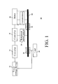
- FIG. 1 is a system architectural view of a closed energy re-circulation system having a transmission shaft according to the present invention.
- a closed energy re-circulation system 10 comprises a power storage device 12, a converter 14, a controller 16, a motor 18, a transmission 20, a transmission shaft 22, a centrifugal device 24, a rotational speed sensor 26, a generator 28 and a load 30.
- the power storage device 12 may be a lead acid battery, a nickel-metal hydride battery or a lithium battery.
- the converter 14 is used to covert a low voltage of the power storage device 12 to a high voltage, and transmits the converted power supply to the controller 16.
- the converter 14 may be a DC-to-DC converter or a DC-to-AC converter.
- the controller 16 receives the power supply transmitted by the converter 14, and outputs a control power supply to the motor 18 used as a driving device, so as to control running of the motor 18, for example, controlling a running rotational speed of the motor 18.
- the controller 16 may be an AC server, a DC server or a frequency converter; the motor may be an AC motor, a DC motor, a magnetic levitation motor or a permanent-magnet motor.
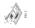
- FIG. 2 is a schematic view of a connection relation among a transmission, a motor and a transmission shaft according to the present invention.
- the transmission 20 is disposed between the motor 18 and the transmission shaft 22.
- the transmission 20 coverts the running rotational speed of the motor 18 to different rotational speeds, so as to rotate the transmission shaft 22.
- the transmission 20 may increase or decrease the running rotational speed of the motor 18.
- the transmission 20 may be a non-continuous variable transmission or a continuous variable transmission.
- the transmission 20 does not need to be disposed between the motor 18 and the transmission shaft 22, instead, the motor 18 directly connects and drives the transmission shaft 22.
- FIG. 3 is a schematic view of a centrifugal device disposed on a transmission shaft according to the present invention.
- the centrifugal device 24 is disposed on the transmission shaft 22.
- the centrifugal device 24 is formed by a coupling portion 32, a connection portion 34, and a sphere 36.
- the coupling portion 32 of the centrifugal device 24 is coupled to the transmission shaft 22.
- the structure of the centrifugal device 24 of the embodiment is not intended to limit the present invention, and any structure of the centrifugal device that may achieve functions of the centrifugal device 24 of this embodiment is applicable in the present invention.
- the transmission shaft having kinetic energy of the rotation of the transmission 20 (the motor 18 in another embodiment, as shown by dashed lines in FIG. 1 ) and kinetic energy generated by the inertia effect of the sphere 36 of the centrifugal device 24 at the same time is used to rotate the generator 28 serving as the driven device.
- the transmission shaft 22 rotates the generator 28, such that the generator 28 generates electric power.
- the electric power generated by the generator 28 is provided for the power storage device 12 and the load 30.
- the generator 28 may be a DC generator or an AC generator.
- the rotational speed sensor 26 detects the rotational speed of the transmission shaft 22 and generates a rotational speed signal.
- the rotational speed signal detected by the rotational speed sensor 26 is transmitted to the controller 16.
- the controller 16 controls the running rotational speed of the motor 18 according to the received rotational speed signal, that is to say, the controller 16 controls the rotational speed of the transmission shaft 22 indirectly.
- the converter 14 coverts the low voltage of the power storage device 12 to the high voltage, and transmits the high-voltage power supply to the controller 16.
- the controller 16 generates the control power supply from the received high-voltage power supply according the rotational speed signal of the rotational speed sensor 26, and outputs the control power supply to the motor 18 to control the running of the motor 18 (such as controlling the running rotational speed of the motor 18).
- the rotational speed sensor 26 transmits the detected rotational speed signal generated by the stillness or low rotational speed of the transmission shaft 22 to the controller 16.
- the rotational speed signal of stillness or low rotational speed is lower than a value of the rotational speed preset by the controller 16, and therefore, the controller 16 increases the control power output to the motor 18, such that the running rotational speed of the motor 18 is increased.
- the motor 18 with the increased rotational speed drives the transmission 20 to rotate the transmission shaft 22, such that the rotational speed of the transmission shaft 22 is increased (in another embodiment, the motor 18 directly rotates the transmission shaft 22, as shown by dashed lines in FIG. 1 ).
- the above operation steps are operated repeatedly, so as to gradually adjust the running rotational speed of the transmission shaft 22 to the rotational speed preset by the controller 16.
- the transmission 20 is disposed between the motor 18 and the transmission shaft 22.
- the rotational speed of the transmission shaft 22 may have a multiple relation with the rotational speed of the motor 18. Therefore, the rotational speed of the transmission shaft 22 is increased, and the generator 28 rotated by the transmission shaft 22 can generate a better power generation efficiency.
- the rotating transmission shaft 22 propels the sphere 36 of the centrifugal device 24 to rotate.
- the rotating sphere 36 generates the centrifugal force.
- the centrifugal force generated by the sphere 36 is greater.
- the centrifugal force of the sphere 36 forms an inertia effect.
- the inertia effect is applied to the transmission shaft 22 through the coupling portion 32 and the connection portion 34.
- the transmission shaft 22 where the inertia effect is applied rotates the generator 28, such that the generator 28 generates electric power.
- the electric power generated by the generator 28 may be provided for the load 30 and may be used to charge the power storage device 12.
- the power storage device 12 provides the power supply for the motor 18 through the converter 14 and the controller 16.
- the generator 28 generates the electric power to charge the power storage device 12, such that an energy re-circulation of a conversion from electric energy to kinetic energy and from kinetic energy to electric energy in the closed energy re-circulation system 10 is achieved.
- the inertia effect formed by the centrifugal force of the centrifugal device 24 is applied to the transmission shaft 22, and the kinetic energy of the running motor 18 is applied to the transmission shaft 22, such that the generator 28 generates more electric power.
- the generator 28 generates the electric power of a fixed amount.
- the kinetic energy that the motor 18 applies to the transmission shaft 22 may be reduced, thereby improving the power generation efficiency of the closed energy re-circulation system 10 and even making the electric energy of the power generated by the generator 28 greater than the electric energy (the electric energy is provided by the controller 16) consumed by the motor 18 to rotate the generator 28 through the transmission shaft 22. In this manner, an efficacy of energy regeneration can be achieved.
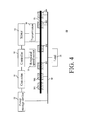
- FIG 4 is a system architectural view of another closed energy re-circulation system having a transmission shaft according to the present invention.
- a structure of a closed energy re-circulation system 40 of FIG. 4 is different from the structure of the closed energy re-circulation system 10 of FIG. 1 in that: multiple centrifugal devices 241 and 242 are disposed on the transmission shaft 22, and the transmission shaft 22 rotates multiple generators 281, 282, 283 and 284.
- a power supply generated by the generators 281, 282, 283 and 284 is transmitted to a bus 38, and the power storage device 12 and the load 30 derive the power supply from the bus 38.
- An operation method of the closed energy re-circulation system 40 of FIG. 4 is the same as the operation method of the closed energy re-circulation system 10 of FIG. 1 . Descriptions of the operation method are omitted herein.
- the driving device may be a water turbine, a gas turbine or a blade.
- Such driving device uses water power, thermal power or wind power to respectively drive a hydroelectric generator, a thermal generator or a wind driven generator of the water turbine, the gas turbine, an engine, a turbine, a steam engine or a blade.
- the system of the transmission shaft having the centrifugal device may enable such generator to have higher power generation efficiency and generate more electric power.
- the transmission shaft having the centrifugal device may be applied in vehicles such as cars and steamships.
- an engine of the car rotates the transmission shaft having the centrifugal device, and the transmission shaft drives wheels to run.
- the engine with the transmission shaft having the centrifugal device may consume fewer resources (such as gasoline) and generate higher running efficiency, therefore achieving efficacies of saving energy, reducing carbon and protecting environment.
- An advantage of the present invention lies in that a transmission shaft having a centrifugal device is provided.
- a driven device When a driven device generates a certain amount of energy, an inertia effect formed by a centrifugal force of the centrifugal device is applied to the transmission shaft, which may reduce energy consumed by a driving device to drive the driven device, and may further make energy generated by the driven device greater than the energy consumed by the driving device to drive the driven device, so as to achieve an energy regeneration efficacy, thereby effectively reducing consumption of earth resources and effectively solving a problem of earth environmental protection.
Landscapes
- Engineering & Computer Science (AREA)
- Chemical & Material Sciences (AREA)
- Combustion & Propulsion (AREA)
- Mechanical Engineering (AREA)
- General Engineering & Computer Science (AREA)
- Connection Of Motors, Electrical Generators, Mechanical Devices, And The Like (AREA)
- Control Of Eletrric Generators (AREA)
Abstract
A transmission shaft (22) is disposed between a driving device (18) and at least one driven device (28). At least one centrifugal device (24) is disposed on the transmission shaft. The centrifugal device generates a centrifugal force and applies an inertia affect formed by the centrifugal force to the transmission shaft, so as to drive the transmission shaft to rotate. Energy generated by the driven device (28) is greater than energy consumed when the driving device drives the driven device, thereby effectively reducing the consumption of earth resources and effectively solving a problem of earth environmental protection.
Description
- The present invention relates to a transmission shaft having a centrifugal device and disposed between a driving device and a driven device, and a transmission method thereof.
- As people's quality of life improves gradually, electrical appliances and power equipment (such as cars and steamships) are widely used in life or work. And energy resources of the electrical appliances and the power equipment are mostly petroleum, natural gas, solar energy and nuclear power. However, such energy resources all have problems, for example, the energy resources may be exhausted, or have technical problem to be solved in usage, or have great danger in use.
- When a transmission shaft transmits motive power to a power generation device to generate electric power, or transmits motive power to a power device to generate a driving force, a driving device and a driven device both have energy dissipation, and the transmission shaft also has energy loss during transmission. As a result, an entire efficiency is reduced, and therefore more energy needs to be consumed, thereby causing more problems of earth environmental protection.
- The present invention provides a transmission shaft having a centrifugal device. When a driven device generates a certain amount of energy, the transmission shaft having the centrifugal device may reduce energy consumed by a driving device to drive the driven device, and may further make energy generated by the driven device greater than the energy consumed by the driving device to drive the driven device, thereby effectively reducing consumption of earth resources and effectively solving a problem of earth environmental protection.
- The present invention provides a transmission shaft, which is disposed between a driving device and at least one driven device.
- At least one centrifugal device is disposed on the transmission shaft. The at least one centrifugal device generates a centrifugal force and applies an inertia effect formed by the centrifugal force on the transmission shaft, so as to drive the transmission shaft to rotate.
- In the transmission shaft according to the present invention, the driving device rotates the transmission shaft and propels the at least one centrifugal device. The transmission shaft rotates the at least one driven device.
- In the transmission shaft according to the present invention, the at least one driven device is one of a generator, and a motion mechanism of a car or a steamship.
- In the transmission shaft according to the present invention, a transmission is disposed between the driving device and the transmission shaft, and the transmission is a continuous variable transmission or a non-continuous variable transmission.
- In the transmission shaft according to the present invention, a rotational speed of a motor is controlled by a controller.
- In the transmission shaft according to the present invention, the driving device is one of a water turbine, a gas turbine, a motor, an engine, a turbine, a steam engine, and a blade.
- In the transmission shaft according to the present invention, the motor is one of a direct current (DC) motor, an alternating current (AC) motor, a magnetic levitation motor and a permanent-magnet motor, and the controller is one of a server and a frequency converter.
- In the transmission shaft according to the present invention, a power supply of the controller is provided through a converter converting a low voltage of a power storage device to a high voltage.
- In the transmission shaft according to the present invention, the at least one driven device produces electric power to charge the power storage device.
- In the transmission shaft according to the present invention, the power storage device is one of a lead acid battery, a nickel-metal hydride battery and a lithium battery.
- In the transmission shaft according to the present invention, a rotational speed of the transmission shaft is detected by a rotational speed sensor. A rotational speed signal detected by the rotational speed sensor is transmitted to the controller, and the controller controls the motor according to the rotational speed signal.
- The present invention provides a transmission method of a transmission shaft, in which the transmission shaft is disposed between a driving device and at least one driven device. The transmission method comprises the following steps:
- generating, by at least one centrifugal device disposed on the transmission shaft, a centrifugal force; and
- applying an inertia effect formed by the centrifugal force to the transmission shaft, so as to drive the transmission shaft to rotate.
- The transmission method according to the present invention further comprises the following steps:
- rotating, by the driving device, the transmission shaft, and propelling the centrifugal device; and
- rotating, by the transmission shaft, the at least one driven device.
- In the transmission method according to the present invention, a transmission changes a rotational speed of the driving device and drives the transmission shaft with the changed rotational speed.
- The transmission method according to the present invention further comprises the following steps:
- converting a low voltage of a power storage device to a high voltage, and providing the high voltage to a controller;
- controlling, by the controller, running of the driving device according to the rotational speed of the transmission shaft; and
- producing, by the at least one driven device, electric power to charge the power storage device.
-
-
FIG. 1 is a system architectural view of a closed energy recirculation system having a transmission shaft according to the present invention; -
FIG. 2 is a schematic view of a connection relation among a transmission, a motor and a transmission shaft according to the present invention; and -
FIG. 3 is a schematic view of a centrifugal device disposed on a transmission shaft according to the present invention; and -
FIG. 4 is a system architectural view of another closed energy re-circulation system having a transmission shaft according to the present invention. - A transmission shaft of the present invention is disposed between a driving device and at least one driven device, and at least one centrifugal device is disposed on the transmission shaft. The driving device may be a water turbine, a gas turbine, a motor, an engine, a turbine, a steam engine or a blade (applied to a wind driven generator). The at least one driven device may be a generator or a motion mechanism (such as a wheel or a screw-propeller) of a car or a steamship.
- The driving device rotates the transmission shaft and propels the at least one centrifugal device. With rotation of the transmission shaft, the at least one centrifugal device generates a centrifugal force. When the driving device drives the transmission shaft to rotate at a preset rotational speed, the centrifugal force of the at least one centrifugal device forms an inertia effect which is applied to the transmission shaft. The transmission shaft having kinetic energy of the rotation of the driving device and kinetic energy of the inertia effect generated by the at least one centrifugal device at the same time is used for rotating the at least one driven device, such that when the at least one driven device generates a certain amount of energy (such as electric energy or kinetic energy), the driving device can reduce energy (such as electric energy or kinetic energy) consumed for driving the at least one driven device. That is to say, the driving device can reduce resources that need to be consumed (such as petroleum or natural gases), even can make energy generated by the at least one driven device greater than the energy consumed by the driving device for driving the at least one driven device.
- A structure and technology of the transmission shaft having the centrifugal device of the present invention is illustrated through an embodiment.
-
FIG. 1 is a system architectural view of a closed energy re-circulation system having a transmission shaft according to the present invention. InFIG. 1 , a closedenergy re-circulation system 10 comprises apower storage device 12, aconverter 14, acontroller 16, amotor 18, atransmission 20, atransmission shaft 22, acentrifugal device 24, arotational speed sensor 26, agenerator 28 and aload 30. - The
power storage device 12 may be a lead acid battery, a nickel-metal hydride battery or a lithium battery. - The
converter 14 is used to covert a low voltage of thepower storage device 12 to a high voltage, and transmits the converted power supply to thecontroller 16. Theconverter 14 may be a DC-to-DC converter or a DC-to-AC converter. - The
controller 16 receives the power supply transmitted by theconverter 14, and outputs a control power supply to themotor 18 used as a driving device, so as to control running of themotor 18, for example, controlling a running rotational speed of themotor 18. Thecontroller 16 may be an AC server, a DC server or a frequency converter; the motor may be an AC motor, a DC motor, a magnetic levitation motor or a permanent-magnet motor. -
FIG. 2 is a schematic view of a connection relation among a transmission, a motor and a transmission shaft according to the present invention. InFIG. 1 andFIG. 2 , thetransmission 20 is disposed between themotor 18 and thetransmission shaft 22. Thetransmission 20 coverts the running rotational speed of themotor 18 to different rotational speeds, so as to rotate thetransmission shaft 22. Thetransmission 20 may increase or decrease the running rotational speed of themotor 18. Thetransmission 20 may be a non-continuous variable transmission or a continuous variable transmission. In another embodiment, thetransmission 20 does not need to be disposed between themotor 18 and thetransmission shaft 22, instead, themotor 18 directly connects and drives thetransmission shaft 22. -
FIG. 3 is a schematic view of a centrifugal device disposed on a transmission shaft according to the present invention. InFIG. 3 , thecentrifugal device 24 is disposed on thetransmission shaft 22. Thecentrifugal device 24 is formed by acoupling portion 32, aconnection portion 34, and asphere 36. Thecoupling portion 32 of thecentrifugal device 24 is coupled to thetransmission shaft 22. The structure of thecentrifugal device 24 of the embodiment is not intended to limit the present invention, and any structure of the centrifugal device that may achieve functions of thecentrifugal device 24 of this embodiment is applicable in the present invention. - In
FIG. 1 to FIG. 3 , when thetransmission 20 rotates the transmission shaft 22 (in another embodiment, themotor 18 directly rotates thetransmission shaft 22, as shown by dashed lines inFIG. 1 ), thetransmission shaft 22 propels thecentrifugal device 24 to rotate. The rotatingcentrifugal device 24 make thesphere 36 generate a centrifugal force. As a rotational speed of thecentrifugal device 24 propelled by thetransmission shaft 22 becomes higher, the centrifugal force generated by thesphere 36 is greater. When thetransmission shaft 22 keeps rotating at a certain rotational speed, an inertia effect is formed by the centrifugal force of thesphere 36 and is applied to thetransmission shaft 22. - The transmission shaft having kinetic energy of the rotation of the transmission 20 (the
motor 18 in another embodiment, as shown by dashed lines inFIG. 1 ) and kinetic energy generated by the inertia effect of thesphere 36 of thecentrifugal device 24 at the same time is used to rotate thegenerator 28 serving as the driven device. Thetransmission shaft 22 rotates thegenerator 28, such that thegenerator 28 generates electric power. The electric power generated by thegenerator 28 is provided for thepower storage device 12 and theload 30. Thegenerator 28 may be a DC generator or an AC generator. - The
rotational speed sensor 26 detects the rotational speed of thetransmission shaft 22 and generates a rotational speed signal. The rotational speed signal detected by therotational speed sensor 26 is transmitted to thecontroller 16. Thecontroller 16 controls the running rotational speed of themotor 18 according to the received rotational speed signal, that is to say, thecontroller 16 controls the rotational speed of thetransmission shaft 22 indirectly. - An operation method of the closed
energy re-circulation system 10 of this embodiment is hereinafter illustrated with references toFIG. 1 to FIG. 3 . - First, the
converter 14 coverts the low voltage of thepower storage device 12 to the high voltage, and transmits the high-voltage power supply to thecontroller 16. - The
controller 16 generates the control power supply from the received high-voltage power supply according the rotational speed signal of therotational speed sensor 26, and outputs the control power supply to themotor 18 to control the running of the motor 18 (such as controlling the running rotational speed of the motor 18). - When the
transmission shaft 22 is static or the rotational speed thereof does not reach the rotational speed set by thecontroller 16, therotational speed sensor 26 transmits the detected rotational speed signal generated by the stillness or low rotational speed of thetransmission shaft 22 to thecontroller 16. The rotational speed signal of stillness or low rotational speed is lower than a value of the rotational speed preset by thecontroller 16, and therefore, thecontroller 16 increases the control power output to themotor 18, such that the running rotational speed of themotor 18 is increased. Themotor 18 with the increased rotational speed drives thetransmission 20 to rotate thetransmission shaft 22, such that the rotational speed of thetransmission shaft 22 is increased (in another embodiment, themotor 18 directly rotates thetransmission shaft 22, as shown by dashed lines inFIG. 1 ). The above operation steps are operated repeatedly, so as to gradually adjust the running rotational speed of thetransmission shaft 22 to the rotational speed preset by thecontroller 16. - The
transmission 20 is disposed between themotor 18 and thetransmission shaft 22. Through a speed variable function of thetransmission 20, the rotational speed of thetransmission shaft 22 may have a multiple relation with the rotational speed of themotor 18. Therefore, the rotational speed of thetransmission shaft 22 is increased, and thegenerator 28 rotated by thetransmission shaft 22 can generate a better power generation efficiency. - The rotating
transmission shaft 22 propels thesphere 36 of thecentrifugal device 24 to rotate. The rotatingsphere 36 generates the centrifugal force. As the rotational speed of thecentrifugal device 24 propelled by thetransmission shaft 22 becomes higher, the centrifugal force generated by thesphere 36 is greater. When the rotational speed of thetransmission shaft 22 reaches the preset rotational speed, the centrifugal force of thesphere 36 forms an inertia effect. The inertia effect is applied to thetransmission shaft 22 through thecoupling portion 32 and theconnection portion 34. - The
transmission shaft 22 where the inertia effect is applied rotates thegenerator 28, such that thegenerator 28 generates electric power. The electric power generated by thegenerator 28 may be provided for theload 30 and may be used to charge thepower storage device 12. - The
power storage device 12 provides the power supply for themotor 18 through theconverter 14 and thecontroller 16. Thegenerator 28 generates the electric power to charge thepower storage device 12, such that an energy re-circulation of a conversion from electric energy to kinetic energy and from kinetic energy to electric energy in the closedenergy re-circulation system 10 is achieved. - When the rotational speed of the
transmission shaft 22 reaches the preset rotational speed, the inertia effect formed by the centrifugal force of thecentrifugal device 24 is applied to thetransmission shaft 22, and the kinetic energy of the runningmotor 18 is applied to thetransmission shaft 22, such that thegenerator 28 generates more electric power. In another situation, thegenerator 28 generates the electric power of a fixed amount. Since the inertia effect formed by the centrifugal force of thecentrifugal device 24 is applied to thetransmission shaft 22, the kinetic energy that themotor 18 applies to thetransmission shaft 22 may be reduced, thereby improving the power generation efficiency of the closedenergy re-circulation system 10 and even making the electric energy of the power generated by thegenerator 28 greater than the electric energy (the electric energy is provided by the controller 16) consumed by themotor 18 to rotate thegenerator 28 through thetransmission shaft 22. In this manner, an efficacy of energy regeneration can be achieved. -
FIG 4 is a system architectural view of another closed energy re-circulation system having a transmission shaft according to the present invention. A structure of a closedenergy re-circulation system 40 ofFIG. 4 is different from the structure of the closedenergy re-circulation system 10 ofFIG. 1 in that: multiplecentrifugal devices transmission shaft 22, and thetransmission shaft 22 rotatesmultiple generators generators bus 38, and thepower storage device 12 and theload 30 derive the power supply from thebus 38. - An operation method of the closed
energy re-circulation system 40 ofFIG. 4 is the same as the operation method of the closedenergy re-circulation system 10 ofFIG. 1 . Descriptions of the operation method are omitted herein. - In another embodiment, the driving device may be a water turbine, a gas turbine or a blade. Such driving device uses water power, thermal power or wind power to respectively drive a hydroelectric generator, a thermal generator or a wind driven generator of the water turbine, the gas turbine, an engine, a turbine, a steam engine or a blade. Similarly, the system of the transmission shaft having the centrifugal device may enable such generator to have higher power generation efficiency and generate more electric power.
- In another embodiment, the transmission shaft having the centrifugal device may be applied in vehicles such as cars and steamships. For example, an engine of the car rotates the transmission shaft having the centrifugal device, and the transmission shaft drives wheels to run. Similarly, the engine with the transmission shaft having the centrifugal device may consume fewer resources (such as gasoline) and generate higher running efficiency, therefore achieving efficacies of saving energy, reducing carbon and protecting environment.
- An advantage of the present invention lies in that a transmission shaft having a centrifugal device is provided. When a driven device generates a certain amount of energy, an inertia effect formed by a centrifugal force of the centrifugal device is applied to the transmission shaft, which may reduce energy consumed by a driving device to drive the driven device, and may further make energy generated by the driven device greater than the energy consumed by the driving device to drive the driven device, so as to achieve an energy regeneration efficacy, thereby effectively reducing consumption of earth resources and effectively solving a problem of earth environmental protection.
- Although the present invention is described above with reference to preferred embodiments and exemplary accompanying drawings, the embodiments should not be regarded as a limitation of the present invention. Any modifications, omissions and variations on content of shapes and implementations made by persons skilled in the art shall fall within the scope of the claims of the present invention.
Claims (15)
- A transmission shaft, disposed between a driving device and at least one driven device, wherein
at least one centrifugal device is disposed on the transmission device, the at least one centrifugal device generates a centrifugal force and applies an inertia effect formed by the centrifugal force on the transmission shaft, so as to drive the transmission shaft to rotate. - The transmission shaft according to claim 1, wherein the driving device rotates the transmission shaft and propels the at least one centrifugal device, the transmission shaft rotates the at least one driven device.
- The transmission shaft according to claim 1 or 2, wherein the at least one driven device is one of a generator, and a motion mechanism of a steamship or a car.
- The transmission shaft according to any preceding claim, wherein a transmission is disposed between the driving device and the transmissions shaft, and the transmission is a continuous variable transmission or a non-continuous variable transmission.
- The transmission shaft according to any preceding claim, wherein the driving device is one of a water turbine, a gas turbine, a motor, an engine, a turbine, a steam engine and a blade.
- The transmission shaft according to claim 5, wherein running of the motor is controlled by a controller.
- The transmission shaft according to claim 6, wherein the motor is one of a direct current (DC) motor, an alternating current (AC) motor, a magnetic levitation motor and a permanent-magnet motor, and the controller is one of a server or a frequency converter.
- The transmission shaft according to claim 6 or 7, wherein a power supply of the controller is provided through a converter converting a low voltage of a power storage device to a high voltage.
- The transmission shaft according to claim 8, wherein the at least one driven device produces electric power to charge the power storage device.
- The transmission shaft according to claim 8 or 9, wherein the power storage device is one of a lead acid battery, a nickel-metal hydride battery and a lithium battery.
- The transmission shaft according to any of claims 5 to 10, wherein a rotational speed of the transmission shaft is detected by a rotational speed sensor, a rotational speed signal detected by the rotational speed sensor is transmitted to the controller, and the controller controls the motor according to the rotational speed signal.
- The transmission method of a transmission shaft, wherein the transmission shaft is disposed between a driving device and at least one driven device, the transmission method comprising:generating, by at least one centrifugal device disposed on the transmission shaft, a centrifugal force; and applying an inertia effect formed by the centrifugal force to the transmission shaft, so as to drive the transmission shaft to rotate.
- The transmission method according to claim 12, further comprising:rotating, by the driving device, the transmission shaft, and propelling the centrifugal device; androtating, by the transmission shaft, the at least one driven device.
- The transmission method according to claim 12 or 13, wherein a transmission changes a rotational speed of the driving device and drives the transmission shaft with the changed rotational speed.
- The transmission method according to claim 12, 13 or 14, further comprising:converting a low voltage of a power storage device to a high voltage, and providing the high voltage to a controller;controlling, by the controller, running of the driving device according to the rotational speed of the transmission shaft; andproducing, by the at least one driven device, electric power to charge the power storage device.
Applications Claiming Priority (1)
| Application Number | Priority Date | Filing Date | Title |
|---|---|---|---|
| TW100117886A TW201248009A (en) | 2011-05-23 | 2011-05-23 | Transmission shaft with centrifugal device and transmission method thereof |
Publications (1)
| Publication Number | Publication Date |
|---|---|
| EP2527690A2 true EP2527690A2 (en) | 2012-11-28 |
Family
ID=46168190
Family Applications (1)
| Application Number | Title | Priority Date | Filing Date |
|---|---|---|---|
| EP12168889A Withdrawn EP2527690A2 (en) | 2011-05-23 | 2012-05-22 | Transmission shaft having centrifugal device and transmission method thereof |
Country Status (5)
| Country | Link |
|---|---|
| US (1) | US20120299424A1 (en) |
| EP (1) | EP2527690A2 (en) |
| JP (1) | JP2012241907A (en) |
| CN (1) | CN102795104A (en) |
| TW (1) | TW201248009A (en) |
Families Citing this family (3)
| Publication number | Priority date | Publication date | Assignee | Title |
|---|---|---|---|---|
| CN105811693A (en) * | 2014-12-31 | 2016-07-27 | 杭州磁控科技有限公司 | Extended range electric vehicle and driving, braking and electric energy supplement method thereof |
| CN110061254B (en) * | 2019-03-04 | 2021-01-26 | 惠州亿纬锂能股份有限公司 | Linkage transmission structure of button cell manufacturing equipment |
| US20230242117A1 (en) * | 2022-01-31 | 2023-08-03 | Gregory Clarence Ettel | Transmission-driven generator on an electric vehicle |
Family Cites Families (13)
| Publication number | Priority date | Publication date | Assignee | Title |
|---|---|---|---|---|
| US4233858A (en) * | 1976-12-27 | 1980-11-18 | The Garrett Corporation | Flywheel drive system having a split electromechanical transmission |
| US5343970A (en) * | 1992-09-21 | 1994-09-06 | Severinsky Alex J | Hybrid electric vehicle |
| EP0749196A3 (en) * | 1995-02-22 | 1997-07-30 | Seiko Instr Inc | Power unit and electronic equipment comprising the same |
| US6433450B1 (en) * | 2000-11-28 | 2002-08-13 | Wen-Ping Chao | Power generating system with physical energy to enhance output |
| JP3744414B2 (en) * | 2001-11-29 | 2006-02-08 | トヨタ自動車株式会社 | Vehicle control device |
| US7105939B2 (en) * | 2003-05-08 | 2006-09-12 | Motion Charge, Inc. | Electrical generator having an oscillator containing a freely moving internal element to improve generator effectiveness |
| US6962223B2 (en) * | 2003-06-26 | 2005-11-08 | George Edmond Berbari | Flywheel-driven vehicle |
| JP4481103B2 (en) * | 2004-08-10 | 2010-06-16 | 本田技研工業株式会社 | Vehicle power generation control device and vehicle equipped with the device |
| US20080001579A1 (en) * | 2005-12-30 | 2008-01-03 | Kenneth Claypool | Gravity propelled generator |
| JP2010058629A (en) * | 2008-09-03 | 2010-03-18 | Toyota Motor Corp | Hybrid vehicle |
| US20100164233A1 (en) * | 2008-10-14 | 2010-07-01 | Bobby Lewis Bates | Centrifugal torque amplifyer |
| AU2009202978A1 (en) * | 2009-04-24 | 2010-11-11 | Green-Tech Holdings Sdn. Bhd. | Uninterrupted battery operated generator system |
| US8427083B2 (en) * | 2010-06-28 | 2013-04-23 | Momentum Power, Inc. | Power distribution system |
-
2011
- 2011-05-23 TW TW100117886A patent/TW201248009A/en unknown
-
2012
- 2012-05-22 US US13/477,917 patent/US20120299424A1/en not_active Abandoned
- 2012-05-22 EP EP12168889A patent/EP2527690A2/en not_active Withdrawn
- 2012-05-22 JP JP2012116480A patent/JP2012241907A/en active Pending
- 2012-05-23 CN CN201210162648XA patent/CN102795104A/en active Pending
Non-Patent Citations (1)
| Title |
|---|
| None |
Also Published As
| Publication number | Publication date |
|---|---|
| CN102795104A (en) | 2012-11-28 |
| JP2012241907A (en) | 2012-12-10 |
| US20120299424A1 (en) | 2012-11-29 |
| TW201248009A (en) | 2012-12-01 |
Similar Documents
| Publication | Publication Date | Title |
|---|---|---|
| CN103332284B (en) | A kind of energy management of hybrid ship electric power propelling system and control method | |
| CN102297082A (en) | Overspeed protection system and method | |
| CN101598113B (en) | Wind power plant generation device | |
| CN207459902U (en) | energy storage power generation device and power generation system | |
| US20120299425A1 (en) | Closed energy combined cycle system and operation method thereof | |
| CN101604865B (en) | Wind power generation system for low-voltage DC power supply | |
| EP2527690A2 (en) | Transmission shaft having centrifugal device and transmission method thereof | |
| CN107054069A (en) | A kind of method that utilization wind energy supplements electric automobile electric power storage | |
| CN102136776A (en) | A multi-motor combined drive assembly | |
| Liu et al. | Comparison of outer-rotor permanent magnet machines for in-wheel drives | |
| CN106640535B (en) | Multi-dimensional wind energy hybrid shaft power generation system | |
| CN106930899B (en) | The electric power system and method for supplying power to of a kind of yaw motor in wind turbine | |
| CN103516296A (en) | Motor power supply control system | |
| WO2010118777A1 (en) | Apparatus for generating current from natural and renewable energy | |
| CN103036374A (en) | Self-energy motor-driven ship | |
| CN106004465A (en) | Electric vehicle wind energy utilization device and realizing method thereof | |
| WO2022146340A2 (en) | A method for energy efficiency and an equipment operating according to this method | |
| TWI463068B (en) | Synchronous generator for direct driving wind power/tide | |
| CN103280857B (en) | A kind of counteraction flyback control method improving microsatellite energy utilization rate | |
| WO2008122167A1 (en) | An operating control method of a servo control system of a cascade motor assembly | |
| CN205669458U (en) | A kind of electric power system of the yaw motor in blower fan | |
| RU157032U1 (en) | COMBINED ENERGY INSTALLATION OF VEHICLE | |
| CN2854910Y (en) | On-off-grid wind generation electric two-use machine with multifunction of simple start | |
| CN203543704U (en) | Parallelly connected power system of motor vehicle | |
| CN101609998B (en) | A wind power storage system |
Legal Events
| Date | Code | Title | Description |
|---|---|---|---|
| PUAI | Public reference made under article 153(3) epc to a published international application that has entered the european phase |
Free format text: ORIGINAL CODE: 0009012 |
|
| 17P | Request for examination filed |
Effective date: 20120522 |
|
| AK | Designated contracting states |
Kind code of ref document: A2 Designated state(s): AL AT BE BG CH CY CZ DE DK EE ES FI FR GB GR HR HU IE IS IT LI LT LU LV MC MK MT NL NO PL PT RO RS SE SI SK SM TR |
|
| AX | Request for extension of the european patent |
Extension state: BA ME |
|
| STAA | Information on the status of an ep patent application or granted ep patent |
Free format text: STATUS: THE APPLICATION HAS BEEN WITHDRAWN |
|
| 18W | Application withdrawn |
Effective date: 20150513 |