EP2527683A1 - Hybrid tape for robotic transmission - Google Patents
Hybrid tape for robotic transmission Download PDFInfo
- Publication number
- EP2527683A1 EP2527683A1 EP12167312A EP12167312A EP2527683A1 EP 2527683 A1 EP2527683 A1 EP 2527683A1 EP 12167312 A EP12167312 A EP 12167312A EP 12167312 A EP12167312 A EP 12167312A EP 2527683 A1 EP2527683 A1 EP 2527683A1
- Authority
- EP
- European Patent Office
- Prior art keywords
- hybrid tape
- inner member
- outer member
- hybrid
- tape
- Prior art date
- Legal status (The legal status is an assumption and is not a legal conclusion. Google has not performed a legal analysis and makes no representation as to the accuracy of the status listed.)
- Granted
Links
Images


Classifications
-
- B—PERFORMING OPERATIONS; TRANSPORTING
- B25—HAND TOOLS; PORTABLE POWER-DRIVEN TOOLS; MANIPULATORS
- B25J—MANIPULATORS; CHAMBERS PROVIDED WITH MANIPULATION DEVICES
- B25J9/00—Program-controlled manipulators
- B25J9/10—Program-controlled manipulators characterised by positioning means for manipulator elements
- B25J9/104—Program-controlled manipulators characterised by positioning means for manipulator elements with cables, chains or ribbons
-
- F—MECHANICAL ENGINEERING; LIGHTING; HEATING; WEAPONS; BLASTING
- F16—ENGINEERING ELEMENTS AND UNITS; GENERAL MEASURES FOR PRODUCING AND MAINTAINING EFFECTIVE FUNCTIONING OF MACHINES OR INSTALLATIONS; THERMAL INSULATION IN GENERAL
- F16G—BELTS, CABLES, OR ROPES, PREDOMINANTLY USED FOR DRIVING PURPOSES; CHAINS; FITTINGS PREDOMINANTLY USED THEREFOR
- F16G1/00—Driving-belts
- F16G1/22—Driving-belts consisting of several parts
-
- F—MECHANICAL ENGINEERING; LIGHTING; HEATING; WEAPONS; BLASTING
- F16—ENGINEERING ELEMENTS AND UNITS; GENERAL MEASURES FOR PRODUCING AND MAINTAINING EFFECTIVE FUNCTIONING OF MACHINES OR INSTALLATIONS; THERMAL INSULATION IN GENERAL
- F16G—BELTS, CABLES, OR ROPES, PREDOMINANTLY USED FOR DRIVING PURPOSES; CHAINS; FITTINGS PREDOMINANTLY USED THEREFOR
- F16G1/00—Driving-belts
- F16G1/22—Driving-belts consisting of several parts
- F16G1/26—Driving-belts consisting of several parts in the form of strips or lamellae
-
- Y—GENERAL TAGGING OF NEW TECHNOLOGICAL DEVELOPMENTS; GENERAL TAGGING OF CROSS-SECTIONAL TECHNOLOGIES SPANNING OVER SEVERAL SECTIONS OF THE IPC; TECHNICAL SUBJECTS COVERED BY FORMER USPC CROSS-REFERENCE ART COLLECTIONS [XRACs] AND DIGESTS
- Y10—TECHNICAL SUBJECTS COVERED BY FORMER USPC
- Y10T—TECHNICAL SUBJECTS COVERED BY FORMER US CLASSIFICATION
- Y10T428/00—Stock material or miscellaneous articles
- Y10T428/24—Structurally defined web or sheet [e.g., overall dimension, etc.]
- Y10T428/24942—Structurally defined web or sheet [e.g., overall dimension, etc.] including components having same physical characteristic in differing degree
Definitions
- the present application relates to a hybrid drive tape for robotic transmission.
- the hybrid tape is configured to have an optimal bending fatigue life.
- tension elements are appealing due to their relative simplicity while exhibiting low mass and high stiffness.
- tension elements may include synthetic ropes, metal cables, or even metal tapes.
- Ropes, cables, and tapes allow bending over small diameter pulleys in space constrained applications.
- One shortcoming of ropes and cables is that the fibers or wires flex and abraid each other when they are cyclically bent over a pulley. This abraiding action is worsened by the degree of tension in the rope or cable, as well as by the degree of curvature of the pulleys they wrap around. As the numbers of bending cycles accumulate, the strands eventually saw through themselves and the rope or cable either stretches too much or breaks.
- Metal tapes are solid elements that structurally deform when bent around a pulley. Metal tapes are often favorable over ropes and cables because the abrasion scenario is avoided. However, the cyclic bending causes fatigue in the metal and cracks that may lead to eventual breaking. For applications with very high frequency motions, bending cycles are accumulated rapidly and fatigue limits are a major constraint.
- the system of the present application includes a hybrid tape constructed of two or more separate materials.
- the two materials are combined so that each material is optimized in accordance with the type of loading each experiences during bending, thereby significantly extending the fatigue life of the hybrid tape.
- the hybrid tape is used in a transmission element within a rotor blade on a rotorcraft.
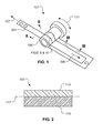
- hybrid tape 103 an exemplary transmission system 101 is illustrated in conjunction with a hybrid tape 103.
- linear motion of hybrid tape 103 is transformed into rotary motion of a rotary drive element 105.
- Hybrid tape 103 is wrapped around rotary drive element 105 such that a movement of hybrid tape 103 in either a direction 107 or 109 results in a rotation 111 of rotary drive element 105.
- a portion of hybrid tape 103 is in bending around the radial contour of rotary drive element 105, an inner part of hybrid tape 103 is in compression while an outer part of hybrid tape 103 is in tension.
- hybrid tape 103 is configured so the compressive bending forces act upon a first material having desirable compressive qualities, while the tensile bending forces act upon a second material having desirable tensile qualities.
- transmission system 101 is merely exemplary of a wide variety of systems for which hybrid tape 103 may be implemented.
- Hybrid tape 103 may take on a wide variety of geometries. Further, hybrid tape 103 may be divided into multiple segments. In some embodiments, hybrid tape 103 may only interact along a segment of rotary drive element 105. For example, hybrid tape 103 may only wrap around a partial circumference, or arc, of rotary drive element 105. Further, hybrid tape 103 may even be coupled to other parts of a transmission system, such as a hammer mechanism configured to transform linear movement in one direction into rotational movement in a different direction. Hybrid tape 103 may also be implemented in a transmission system having multiple rotary drive elements in series.
- rotary drive element 105 need not be cylindrical, rather rotary drive element 105 may be of a variety of shapes and geometries.
- rotary drive element 105 may have a cam-shaped feature configured to produce an eccentric or irregular rotary movement.
- hybrid tape 103 is particularly well suited for implementations dealing with high frequency cyclic movements that may otherwise result in premature failure of a conventional tape due to fatigue.
- Hybrid tape 103 is configured to tolerate high frequency bending cycles without prematurely succumbing to fatigue failure.
- hybrid tape 103 includes an inner member 113 and an outer member 115.
- Inner member 113 is formed with a material having desirable compressive qualities, such that inner member 113 is tailored to exhibit superior fatigue performance in compression induced bending.
- inner member 113 can be formed with a metallic material, such as steel, titanium, aluminum, to name a few.
- inner member 113 is formed with 17-7 TH1050 stainless steel and has a thickness of approximately .002 inch.
- Outer member 115 is formed with a material having desirable tensile qualities, such that outer member 115 is tailored to exhibit superior fatigue performance in tension induced bending.
- outer member 115 can be formed with a composite material comprising of fibers in a matrix material, such as a weave of composite fibers disposed in a resin solution.
- the specific composite material is implementation specific and may be of a wide variety of composite systems known by one skilled in the art.
- outer member 115 has a thickness of approximately .0037 inch and is formed with S2 fiberglass fibers disposed in an E773 epoxy resin matrix. Fibers in a composite material are particularly well suited for load scenarios in which the fibers are being stretched rather than being pushed. As such, composite materials are ideal as a material composition for outer member 115, which is subjected to tension when tape 103 is radially bent around rotary drive element 105.
- Hybrid tape 103 is configured such that a bend neutral axis 117 is located at or near the transition between inner member 113 and outer member 115.
- Bend neutral axis 117 is an axis in which there are no longitudinal stresses or strains. Further, the bend neutral axis 117 is a line of demarcation between compression/tension stresses and strains. The location of bend neutral axis 117 is dependent in part upon the modulus of elasticity and thickness of inner member 113 and outer member 115.
- inner member 113 and outer member 115 are each sized and formed of an appropriate material so that bend neutral axis 117 is located at or near the transition between inner member 113 and outer member 115.
- Such a configuration segregates the bending loads so that inner member 113 is subjected to compressive bending loads while outer member 115 is subjected to tensile bending loads.
- hybrid tape 103 is schematically illustrated wrapping around a portion of a rotary drive element, such as rotary drive element 105.
- hybrid tape 103 is in a deflected state such that outer member 115 is in tension, while inner member 113 is in compression.
- the bend neutral axis 117 is the line of demarcation between compressive and tensile loading due to bending.
- One method of manufacturing hybrid tape 103 includes laying up one or more plies of pre-impregnated composite material directly onto inner member 113. The assembly is cured such that the pre-impregnated plies become outer member 115. In such an embodiment of hybrid tape 103, the resin in the pre-impregnated composite plies is relied upon to create a bond between inner member 113 and outer member 115. In other embodiments, such as hybrid tape 501 (illustrated in Figure 5 ), an adhesive layer 503 is applied between inner member 113 and outer member 115 during assembly. It should be appreciated that conventional composite manufacturing techniques may be used to manufacture hybrid tape 103, such as vacuum bagging, molding, and autoclave curing, to name a few.
- the fibers of the composite material can be oriented so as to tailor the modulus of elasticity in bending. Selectively orienting the fibers is a useful tool for tailoring of the modulus of elasticity so as to control the location of bend neutral axis 117 for hybrid tape 103.
- Figure 9 illustrates an embodiment of hybrid tape 103 with outer member 115 having longitudinal fibers 901 oriented parallel with the length of the tape.
- Figure 10 illustrates another embodiment of hybrid tape 103 with outer member 115 having a first set of fibers 1001 being oriented 45 degrees from a longitudinal axis of hybrid tape 103, as well as a second set of fibers 1003 oriented 90 degrees from the first set up fibers 1001.
- the embodiment of outer member 115 in Figure 9 will typically have a higher modulus of elasticity in bending as compared to the embodiment of outer member 115 in Figure 10 , for a given thickness, due to the directions of the fibers.
- Figures 9 and 10 are illustrated to exemplify how the modulus of elasticity of outer member 115 can be tailored by selectively orienting the fibers.
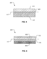
- Hybrid tape 501 is similar to hybrid tape 103, except hybrid tape 501 includes an adhesive layer 503 between inner member 113 and outer member 115.
- Adhesive layer 503 can be used to promote the bond between inner member 113 and outer member 115.
- Adhesive layer 503 is preferably applied in the form of an adhesive film between inner member 113 and outer member 115.
- Adhesive layer 503 is preferably cured during a curing cycle in which the adhesive film is subjected to pressure and/or heat. It should be appreciated that adhesives requiring only an ambient pressure/temperature cure may also be used.
- outer member 115 may be cured prior to assembly with adhesive layer 503 and inner member 113.
- outer member 115 may be cured along with adhesive layer 503 while being assembled with inner member 113.
- Hybrid tape 601 is similar to hybrid tape 103, except hybrid tape 601 includes a plurality of inner members and a plurality of outer members. As in the case of hybrid tape 103, inner members have desirable compressive characteristics while the outer members have desirable tensile characteristics.
- Hybrid tape 601 includes an additional outer member 605.
- Outer member 605 is preferably a composite material having a lower modulus of elasticity and higher strain capability, as compared to outer member 115. For example, if outer member 115 is carbon fiber/epoxy, then outer member 605 can be a fiberglass/epoxy.
- hybrid tape 601 includes an additional inner member 603.
- Inner member 603 is preferably a metallic member having a lower modulus of elasticity than that of inner member 113.
- inner member 113 is stainless steel, then inner member 603 can be titanium.
- An adhesive layer may be used between inner member 113 and inner member 603.
- Hybrid tape 601 is particularly well suited for the tailoring of the location of bend neutral axis 117. Further, having multiple inner members and/or outer members allows hybrid tape 601 to be configured with greater optimization of total tape thickness and neutral bend axis location. Further, it should be appreciated that hybrid tape 601 may only have a single outer member, such as outer member 115. Similarly, it should be appreciated that hybrid tape 601 may only have a single inner member, such as inner member 113. Furthermore, hybrid tape 601 may have any number of inner and outer members.
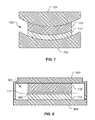
- hybrid tape 103 includes selectively applying a pre-curve during lay-up assembly and curing. Because the inner member 113 is preferably a metallic material, while outer member 115 is preferably a composite material, inner member 113 will typically have a higher thermal coefficient of expansion. As such, heating the assembly during the curing cycle may cause the inner member 113 to expand widthwise greater than the outer member 115. Subsequent cooling of the assembly may result in a greater contraction of inner member 113 as compared to outer member 115. In order to negate any warping that may otherwise occur, hybrid tape is assembled on a lower mold tool 703 having a concave mold surface, as shown in Figure 7 .
- an upper mold tool 701 may also be used to further shape the upper surface of outer member 115.
- Lower mold tool 703 forms a pre-curve in inner member 113 and outer member 115 so that the subsequent cooling of inner member 113 and outer member 115 acts to produce a hybrid tape 103 that is flat.
- the degree of pre-curve in the mold tools is dependent upon the geometry and materials of inner member 113 and outer member 115, as well as the cure temperature.
- hybrid tape 501 can be fabricated by applying inner member 113, adhesive layer 503, and outer member 115 into a closed cavity tool.
- Closed cavity tool preferably has a rigid first tool 801 and a rigid second tool 803.
- the closed cavity tool preferably has one or more stops that dictate the desired final thickness of hybrid tape 501.
- the assembly is heated until the adhesive layer 503 becomes viscous, then first tool 801 and second tool 803 are forced together, causing the adhesive layer to bleed out until the stops are encountered.
- rigid first tool 801 and rigid second tool 803 have curved surfaces configured to generate a pre-curve in hybrid tape 501, similar to the embodiment shown in Figure 7 .
- the hybrid tape system of the present application provides significant advantages, including: 1) providing a hybrid tape that has superior bending fatigue characteristics; 2) providing a hybrid tape that has a inner member particularly well suited for compression and an outer member that is particularly well suited for tension; 3) tailoring the modulus of elasticity of the composite outer member by selectively orienting the fibers; 4) applying a pre-curve to the hybrid tape assembly during processing; and 5) tailoring the location of the neutral bend axis by selecting the geometry and material of the inner member and outer member so that the outer member experiences only tension while the inner member experiences only compression.
Landscapes
- Engineering & Computer Science (AREA)
- General Engineering & Computer Science (AREA)
- Mechanical Engineering (AREA)
- Robotics (AREA)
- Moulding By Coating Moulds (AREA)
- Laminated Bodies (AREA)
- Manipulator (AREA)
Abstract
Description
- The present application relates to a hybrid drive tape for robotic transmission. The hybrid tape is configured to have an optimal bending fatigue life.
- Typically, certain robotic transmissions may use tension elements as an efficient method of transferring actuators forces and motion. Tension elements are appealing due to their relative simplicity while exhibiting low mass and high stiffness. Typically, tension elements may include synthetic ropes, metal cables, or even metal tapes.
- Ropes, cables, and tapes allow bending over small diameter pulleys in space constrained applications. One shortcoming of ropes and cables is that the fibers or wires flex and abraid each other when they are cyclically bent over a pulley. This abraiding action is worsened by the degree of tension in the rope or cable, as well as by the degree of curvature of the pulleys they wrap around. As the numbers of bending cycles accumulate, the strands eventually saw through themselves and the rope or cable either stretches too much or breaks.
- Metal tapes are solid elements that structurally deform when bent around a pulley. Metal tapes are often favorable over ropes and cables because the abrasion scenario is avoided. However, the cyclic bending causes fatigue in the metal and cracks that may lead to eventual breaking. For applications with very high frequency motions, bending cycles are accumulated rapidly and fatigue limits are a major constraint.
- Hence, there is a need for an improved robotic transmission element.
- The novel features believed characteristic of the system of the present application are set forth in the appended claims. However, the system itself, as well as a preferred mode of use, and further objectives and advantages thereof, will best be understood by reference to the following detailed description when read in conjunction with the accompanying drawings, wherein:
-
Figure 1 is a schematic perspective view of a transmission system having a drive tape according to an illustrative embodiment of the present application; -
Figure 2 is a cross-sectional view of a hybrid tape, taken at section lines II-II, according to the preferred embodiment of the present application; -
Figure 3 is a cross-sectional view of the hybrid tape, taken at section lines III-III, according to the preferred embodiment of the present application; -
Figure 4 is a cross-sectional view of the hybrid tape while in a deflected state, according to the preferred embodiment of the present application; -
Figure 5 is a cross-sectional view of a hybrid tape according to an alternative embodiment of the present application; -
Figure 6 is a cross-sectional view of a hybrid tape according to an alternative embodiment of the present application; -
Figure 7 is a cross-sectional view of a manufacturing embodiment of a hybrid tape according to the present application; -
Figure 8 is a cross-sectional view of a manufacturing embodiment of a hybrid tape according to the present application; -
Figure 9 is a detail view of a portion of the hybrid tape, taken fromFigure 1 , according to an embodiment of the present application; and -
Figure 10 is a detail view of a portion of the hybrid tape, taken fromFigure 1 , according to an embodiment of the present application. - The system of the present application includes a hybrid tape constructed of two or more separate materials. The two materials are combined so that each material is optimized in accordance with the type of loading each experiences during bending, thereby significantly extending the fatigue life of the hybrid tape. In one implementation, the hybrid tape is used in a transmission element within a rotor blade on a rotorcraft.
- Referring to
Figure 1 , anexemplary transmission system 101 is illustrated in conjunction with ahybrid tape 103. In the embodiment illustrated, linear motion ofhybrid tape 103 is transformed into rotary motion of arotary drive element 105.Hybrid tape 103 is wrapped aroundrotary drive element 105 such that a movement ofhybrid tape 103 in either adirection rotation 111 ofrotary drive element 105. Because a portion ofhybrid tape 103 is in bending around the radial contour ofrotary drive element 105, an inner part ofhybrid tape 103 is in compression while an outer part ofhybrid tape 103 is in tension. As further discussed herein,hybrid tape 103 is configured so the compressive bending forces act upon a first material having desirable compressive qualities, while the tensile bending forces act upon a second material having desirable tensile qualities. - It should be appreciated that
transmission system 101 is merely exemplary of a wide variety of systems for whichhybrid tape 103 may be implemented.Hybrid tape 103 may take on a wide variety of geometries. Further,hybrid tape 103 may be divided into multiple segments. In some embodiments,hybrid tape 103 may only interact along a segment ofrotary drive element 105. For example,hybrid tape 103 may only wrap around a partial circumference, or arc, ofrotary drive element 105. Further,hybrid tape 103 may even be coupled to other parts of a transmission system, such as a hammer mechanism configured to transform linear movement in one direction into rotational movement in a different direction.Hybrid tape 103 may also be implemented in a transmission system having multiple rotary drive elements in series. It should also be appreciated thatrotary drive element 105 need not be cylindrical, ratherrotary drive element 105 may be of a variety of shapes and geometries. For example,rotary drive element 105 may have a cam-shaped feature configured to produce an eccentric or irregular rotary movement. - It should also be appreciated that
hybrid tape 103 is particularly well suited for implementations dealing with high frequency cyclic movements that may otherwise result in premature failure of a conventional tape due to fatigue.Hybrid tape 103 is configured to tolerate high frequency bending cycles without prematurely succumbing to fatigue failure. - Referring to
Figures 2-4 ,hybrid tape 103 includes aninner member 113 and anouter member 115.Inner member 113 is formed with a material having desirable compressive qualities, such thatinner member 113 is tailored to exhibit superior fatigue performance in compression induced bending. For example,inner member 113 can be formed with a metallic material, such as steel, titanium, aluminum, to name a few. In the illustrated embodiment,inner member 113 is formed with 17-7 TH1050 stainless steel and has a thickness of approximately .002 inch. -
Outer member 115 is formed with a material having desirable tensile qualities, such thatouter member 115 is tailored to exhibit superior fatigue performance in tension induced bending. For example,outer member 115 can be formed with a composite material comprising of fibers in a matrix material, such as a weave of composite fibers disposed in a resin solution. It should be appreciated that the specific composite material is implementation specific and may be of a wide variety of composite systems known by one skilled in the art. In the illustrated embodiment,outer member 115 has a thickness of approximately .0037 inch and is formed with S2 fiberglass fibers disposed in an E773 epoxy resin matrix. Fibers in a composite material are particularly well suited for load scenarios in which the fibers are being stretched rather than being pushed. As such, composite materials are ideal as a material composition forouter member 115, which is subjected to tension whentape 103 is radially bent aroundrotary drive element 105. -
Hybrid tape 103 is configured such that a bendneutral axis 117 is located at or near the transition betweeninner member 113 andouter member 115. Bendneutral axis 117 is an axis in which there are no longitudinal stresses or strains. Further, the bendneutral axis 117 is a line of demarcation between compression/tension stresses and strains. The location of bendneutral axis 117 is dependent in part upon the modulus of elasticity and thickness ofinner member 113 andouter member 115. As such,inner member 113 andouter member 115 are each sized and formed of an appropriate material so that bendneutral axis 117 is located at or near the transition betweeninner member 113 andouter member 115. Such a configuration segregates the bending loads so thatinner member 113 is subjected to compressive bending loads whileouter member 115 is subjected to tensile bending loads. - Referring to
Figure 4 , a portion ofhybrid tape 103 is schematically illustrated wrapping around a portion of a rotary drive element, such asrotary drive element 105. As shown inFigure 4 ,hybrid tape 103 is in a deflected state such thatouter member 115 is in tension, whileinner member 113 is in compression. The bendneutral axis 117 is the line of demarcation between compressive and tensile loading due to bending. - One method of manufacturing
hybrid tape 103 includes laying up one or more plies of pre-impregnated composite material directly ontoinner member 113. The assembly is cured such that the pre-impregnated plies becomeouter member 115. In such an embodiment ofhybrid tape 103, the resin in the pre-impregnated composite plies is relied upon to create a bond betweeninner member 113 andouter member 115. In other embodiments, such as hybrid tape 501 (illustrated inFigure 5 ), anadhesive layer 503 is applied betweeninner member 113 andouter member 115 during assembly. It should be appreciated that conventional composite manufacturing techniques may be used to manufacturehybrid tape 103, such as vacuum bagging, molding, and autoclave curing, to name a few. - Referring briefly to
Figures 9 and 10 , whenouter member 115 is formed with a composite material, the fibers of the composite material can be oriented so as to tailor the modulus of elasticity in bending. Selectively orienting the fibers is a useful tool for tailoring of the modulus of elasticity so as to control the location of bendneutral axis 117 forhybrid tape 103.Figure 9 illustrates an embodiment ofhybrid tape 103 withouter member 115 havinglongitudinal fibers 901 oriented parallel with the length of the tape.Figure 10 illustrates another embodiment ofhybrid tape 103 withouter member 115 having a first set offibers 1001 being oriented 45 degrees from a longitudinal axis ofhybrid tape 103, as well as a second set offibers 1003 oriented 90 degrees from the first set upfibers 1001. The embodiment ofouter member 115 inFigure 9 will typically have a higher modulus of elasticity in bending as compared to the embodiment ofouter member 115 inFigure 10 , for a given thickness, due to the directions of the fibers.Figures 9 and 10 are illustrated to exemplify how the modulus of elasticity ofouter member 115 can be tailored by selectively orienting the fibers. - Referring now to
Figure 5 , an alternative embodimenthybrid tape 501 is illustrated.Hybrid tape 501 is similar tohybrid tape 103, excepthybrid tape 501 includes anadhesive layer 503 betweeninner member 113 andouter member 115.Adhesive layer 503 can be used to promote the bond betweeninner member 113 andouter member 115.Adhesive layer 503 is preferably applied in the form of an adhesive film betweeninner member 113 andouter member 115.Adhesive layer 503 is preferably cured during a curing cycle in which the adhesive film is subjected to pressure and/or heat. It should be appreciated that adhesives requiring only an ambient pressure/temperature cure may also be used. During the assembly ofhybrid tape 501,outer member 115 may be cured prior to assembly withadhesive layer 503 andinner member 113. Alternatively,outer member 115 may be cured along withadhesive layer 503 while being assembled withinner member 113. - Referring now to
Figure 6 , an alternative embodimenthybrid tape 601 is illustrated.Hybrid tape 601 is similar tohybrid tape 103, excepthybrid tape 601 includes a plurality of inner members and a plurality of outer members. As in the case ofhybrid tape 103, inner members have desirable compressive characteristics while the outer members have desirable tensile characteristics.Hybrid tape 601 includes an additionalouter member 605.Outer member 605 is preferably a composite material having a lower modulus of elasticity and higher strain capability, as compared toouter member 115. For example, ifouter member 115 is carbon fiber/epoxy, thenouter member 605 can be a fiberglass/epoxy. Similarly,hybrid tape 601 includes an additionalinner member 603.Inner member 603 is preferably a metallic member having a lower modulus of elasticity than that ofinner member 113. For example, ifinner member 113 is stainless steel, theninner member 603 can be titanium. An adhesive layer may be used betweeninner member 113 andinner member 603.Hybrid tape 601 is particularly well suited for the tailoring of the location of bendneutral axis 117. Further, having multiple inner members and/or outer members allowshybrid tape 601 to be configured with greater optimization of total tape thickness and neutral bend axis location. Further, it should be appreciated thathybrid tape 601 may only have a single outer member, such asouter member 115. Similarly, it should be appreciated thathybrid tape 601 may only have a single inner member, such asinner member 113. Furthermore,hybrid tape 601 may have any number of inner and outer members. - Referring to
Figure 7 , one embodiment ofhybrid tape 103 includes selectively applying a pre-curve during lay-up assembly and curing. Because theinner member 113 is preferably a metallic material, whileouter member 115 is preferably a composite material,inner member 113 will typically have a higher thermal coefficient of expansion. As such, heating the assembly during the curing cycle may cause theinner member 113 to expand widthwise greater than theouter member 115. Subsequent cooling of the assembly may result in a greater contraction ofinner member 113 as compared toouter member 115. In order to negate any warping that may otherwise occur, hybrid tape is assembled on alower mold tool 703 having a concave mold surface, as shown inFigure 7 . Additionally, anupper mold tool 701 may also be used to further shape the upper surface ofouter member 115.Lower mold tool 703 forms a pre-curve ininner member 113 andouter member 115 so that the subsequent cooling ofinner member 113 andouter member 115 acts to produce ahybrid tape 103 that is flat. The degree of pre-curve in the mold tools is dependent upon the geometry and materials ofinner member 113 andouter member 115, as well as the cure temperature. - Referring to
Figure 8 ,hybrid tape 501 can be fabricated by applyinginner member 113,adhesive layer 503, andouter member 115 into a closed cavity tool. Note that the illustrated geometric configuration of the closed cavity tool is merely exemplary of the widely diverse geometric configurations of closed cavity tools contemplated. Closed cavity tool preferably has a rigidfirst tool 801 and a rigidsecond tool 803. The closed cavity tool preferably has one or more stops that dictate the desired final thickness ofhybrid tape 501. During processing, the assembly is heated until theadhesive layer 503 becomes viscous, thenfirst tool 801 andsecond tool 803 are forced together, causing the adhesive layer to bleed out until the stops are encountered. In an alternative embodiment, rigidfirst tool 801 and rigidsecond tool 803 have curved surfaces configured to generate a pre-curve inhybrid tape 501, similar to the embodiment shown inFigure 7 . - The hybrid tape system of the present application provides significant advantages, including: 1) providing a hybrid tape that has superior bending fatigue characteristics; 2) providing a hybrid tape that has a inner member particularly well suited for compression and an outer member that is particularly well suited for tension; 3) tailoring the modulus of elasticity of the composite outer member by selectively orienting the fibers; 4) applying a pre-curve to the hybrid tape assembly during processing; and 5) tailoring the location of the neutral bend axis by selecting the geometry and material of the inner member and outer member so that the outer member experiences only tension while the inner member experiences only compression.
- It is apparent that an application with significant advantages has been described and illustrated. Although the present application is shown in a limited number of forms, it is not limited to just these forms, but is amenable to various changes and modifications without departing from the spirit thereof.
Claims (17)
- A hybrid tape for a transmission system, the hybrid tape comprising:an inner member having a first material suited to withstand compressive forces generated from a bending of the hybrid tape;an outer member having a second material suited to withstand tensile forces generated from a bending of the hybrid tape, the outer member being bonded to the inner member to form the hybrid tape; andwherein the outer member and inner member are each selectively tailored for a specified bending criteria so that the inner member is subjected to primarily compressive forces while the outer member is subjected to primarily tensile forces, when the hybrid tape endures bending associated with the specified bending criteria.
- The hybrid tape according to claim 1, wherein the first material is metallic material.
- The hybrid tape according to claim 1 or claim 2, wherein the second material is composite material.
- The hybrid tape according to claim 1, or of claim 2 or of claim 3, wherein the inner member and the outer member are bonded together with a resin from the second material.
- The hybrid tape according to claim 1 or of claim 2 or of claim 3, wherein the inner member and the outer member are bonded together with an adhesive layer.
- The hybrid tape according to claim 1 or of any of claims 2 to 5, wherein the second material is a composite material having a plurality of fibers, the plurality of fibers being oriented to tailor the modulus of elasticity of the outer member.
- The hybrid tape according to claim 1 or of any of claims 2 to 6, further comprising:a second inner member; anda second outer member.
- A robotic transmission system having a hybrid tape, the robotic transmission system comprising:a rotary drive element;a hybrid tape at least partially wrapped around the rotary drive element, the hybrid tape comprising:a first member being substantially formed of a first material;a second member being substantially formed of a second material, the second member being attached to the first member;wherein an exposed surface of the first member is in contact with the rotary drive element.
- The robotic transmission system according to claim 8, wherein the first material has desirable compressive qualities, while the second material has desirable tensile qualities.
- The robotic transmission system according to claim 8 or claim 9, wherein the first member and the second member are configured such that a bending of the hybrid tape about the rotary drive element results in the first member only experiencing compressive forces and the second member only experiencing tensile forces, the compressive forces and horizontal forces being along a horizontal length of the hybrid tape.
- The robotic transmission system according to claim 8 or claim 9 or claim 10, wherein a transition between the first member and the second member corresponds approximately with a bend neutral axis; or
the hybrid tape according to claim 1, or any of claims 2 to 7 wherein a transition between the inner member and the outer member corresponds approximately with a bend neutral axis. - The robotic transmission system according to claim 11, wherein the bend neutral axis is an axis of demarcation between horizontal compressive forces and horizontal tensile forces in the hybrid tape during bending, such that there are no horizontal stresses in the hybrid tape at the bend neutral axis; or
the hybrid tape of claim 11 wherein the bend neutral axis is an axis of demarcation between compressive forces and tensile forces in the hybrid tape during bending. - A method of manufacturing a hybrid tape, the method comprising:assembling an inner member on a tooled surface of a lower tool, the tooled surface having a concave contour, the inner member substantially conforming to the concave contour;assembling an outer member onto the inner member, the outer member having uncured composite material that substantially conforms to an upper surface of the inner member;curing the inner member and the outer member by applying heat, thereby creating a bond between the inner member and the outer member;cooling the inner member and the outer member, the thermal contraction of the inner member being greater than the outer member so as to cause the inner member and outer member to lay substantially flat.
- The method according to claim 13, further comprising:customizing a degree of the concave contour based upon a predicted cure temperature used in the step of curing the inner member and the outer member.
- The method according to claim 13, further comprising:customizing a degree of the concave contour based upon the contrast between the coefficient of thermal expansion of the inner member to the coefficient of thermal expansion of the outer member.
- The method according to claim 13 or claim 14 or claim 15, further comprising:applying pressure to the inner member and the outer member during the curing step, and optionally or preferablywherein the pressure is applied by translating an upper tool relative to the lower tool.
- The method according to claim 13 or any of claims 14 to 16, further comprising:applying an adhesive between the inner member and the outer member so as to create the bond between the inner member and the outer member.
Applications Claiming Priority (2)
| Application Number | Priority Date | Filing Date | Title |
|---|---|---|---|
| US201161484742P | 2011-05-11 | 2011-05-11 | |
| US13/460,420 US9457465B2 (en) | 2011-05-11 | 2012-04-30 | Hybrid tape for robotic transmission |
Publications (2)
| Publication Number | Publication Date |
|---|---|
| EP2527683A1 true EP2527683A1 (en) | 2012-11-28 |
| EP2527683B1 EP2527683B1 (en) | 2018-03-21 |
Family
ID=46146658
Family Applications (1)
| Application Number | Title | Priority Date | Filing Date |
|---|---|---|---|
| EP12167312.3A Not-in-force EP2527683B1 (en) | 2011-05-11 | 2012-05-09 | Hybrid tape for robotic transmission |
Country Status (5)
| Country | Link |
|---|---|
| US (1) | US9457465B2 (en) |
| EP (1) | EP2527683B1 (en) |
| CN (1) | CN102777540B (en) |
| BR (1) | BR102012011051A2 (en) |
| CA (1) | CA2775887C (en) |
Families Citing this family (2)
| Publication number | Priority date | Publication date | Assignee | Title |
|---|---|---|---|---|
| CN110878813B (en) * | 2019-11-29 | 2021-08-17 | 常州新区三捷电子器材有限公司 | A method of preloading a steel belt |
| DE102020004186A1 (en) * | 2020-03-27 | 2021-09-30 | GKD - Gebr. Kufferath AG. | Process belt with a planar structure, device with a revolving endless belt and use of a process belt |
Citations (4)
| Publication number | Priority date | Publication date | Assignee | Title |
|---|---|---|---|---|
| FR2218000A5 (en) * | 1973-02-09 | 1974-09-06 | Bertin & Cie | |
| JPS52149962U (en) * | 1976-05-11 | 1977-11-14 | ||
| US4342561A (en) * | 1980-06-02 | 1982-08-03 | Borg-Warner Corporation | Power transmission belt |
| EP0392850A2 (en) * | 1989-04-14 | 1990-10-17 | Sumitomo Metal Industries, Ltd. | Method of producing laminated metal belt |
Family Cites Families (23)
| Publication number | Priority date | Publication date | Assignee | Title |
|---|---|---|---|---|
| US2167384A (en) * | 1937-12-22 | 1939-07-25 | Dayton Rubber Mfg Co | Belt |
| US2511581A (en) * | 1946-06-24 | 1950-06-13 | Gail G Grigsby | Conveyer belt |
| US2793150A (en) * | 1951-12-06 | 1957-05-21 | British Tyre & Rubber Company | Conveyor belts |
| US3315704A (en) * | 1963-06-17 | 1967-04-25 | Gen Connector Corp | Flexible bellows |
| GB1386404A (en) * | 1971-03-11 | 1975-03-05 | Dunlop Ltd | Power transmission conveyor and vehicle track belts |
| DE2202041A1 (en) * | 1972-01-17 | 1973-07-26 | Baublys Mikas Dr Ing | STRAPS WITH MULTIPLE LAYERS OF METAL AND METHOD OF MANUFACTURING THE SAME |
| US4004467A (en) * | 1972-08-03 | 1977-01-25 | Dunlop Limited | Conveyor belting |
| US3830113A (en) * | 1972-12-29 | 1974-08-20 | Goodyear Tire & Rubber | Transmission belt structure |
| US3919892A (en) * | 1974-08-12 | 1975-11-18 | Dayco Corp | Endless power transmission belt structure |
| US4022071A (en) * | 1976-01-22 | 1977-05-10 | Abatemarco Michael R | Steel cord belt reinforced transmission belt |
| US4250223A (en) * | 1978-07-07 | 1981-02-10 | Dearborn Rubber Company | Belt type expansion joints |
| FR2452035A1 (en) * | 1979-03-23 | 1980-10-17 | David Bernard | REINFORCED TRAPEZOIDAL BELT WITH METAL CONTACTS |
| US4553951A (en) * | 1983-06-02 | 1985-11-19 | The Gerber Scientific Instrument Company | Non-slip pulley and belt drive |
| IT1186158B (en) * | 1985-12-20 | 1987-11-18 | Pirelli Transmissioni Ind Spa | TRAPEZOIDAL BELT, IN PARTICULAR FOR CONTINUOUS SPEED VARIATORS |
| FR2597182B1 (en) * | 1986-04-11 | 1988-08-05 | Hutchinson | IMPROVED TRAPEZOIDAL TRANSMISSION BELT AND MANUFACTURING METHOD THEREOF |
| US5316651A (en) * | 1991-12-03 | 1994-05-31 | Xerox Corporation | Process for preparing selectively stressed endless belts |
| JPH0740353A (en) * | 1993-07-27 | 1995-02-10 | Bando Chem Ind Ltd | Belt manufacturing method |
| US5682795A (en) * | 1995-07-10 | 1997-11-04 | Smart Machines | Robotic joint using metal bands |
| JP2005226754A (en) * | 2004-02-13 | 2005-08-25 | Bando Chem Ind Ltd | Transmission belt |
| CN101048276A (en) * | 2004-09-24 | 2007-10-03 | 伊藤忠商事株式会社 | thin layer laminate |
| DE102006003705A1 (en) * | 2006-01-26 | 2007-08-02 | Voith Patent Gmbh | conveyor belt |
| JP2009538250A (en) * | 2006-05-15 | 2009-11-05 | アルコア インク. | Structure of reinforced hybrid and manufacturing method thereof |
| JP5415956B2 (en) | 2007-11-09 | 2014-02-12 | バンドー化学株式会社 | Transmission belt |
-
2012
- 2012-04-30 US US13/460,420 patent/US9457465B2/en not_active Expired - Fee Related
- 2012-05-02 CA CA2775887A patent/CA2775887C/en active Active
- 2012-05-08 CN CN201210140593.2A patent/CN102777540B/en not_active Expired - Fee Related
- 2012-05-09 EP EP12167312.3A patent/EP2527683B1/en not_active Not-in-force
- 2012-05-10 BR BRBR102012011051-2A patent/BR102012011051A2/en not_active Application Discontinuation
Patent Citations (4)
| Publication number | Priority date | Publication date | Assignee | Title |
|---|---|---|---|---|
| FR2218000A5 (en) * | 1973-02-09 | 1974-09-06 | Bertin & Cie | |
| JPS52149962U (en) * | 1976-05-11 | 1977-11-14 | ||
| US4342561A (en) * | 1980-06-02 | 1982-08-03 | Borg-Warner Corporation | Power transmission belt |
| EP0392850A2 (en) * | 1989-04-14 | 1990-10-17 | Sumitomo Metal Industries, Ltd. | Method of producing laminated metal belt |
Also Published As
| Publication number | Publication date |
|---|---|
| CN102777540A (en) | 2012-11-14 |
| CA2775887A1 (en) | 2012-11-11 |
| BR102012011051A2 (en) | 2013-07-30 |
| US20120289371A1 (en) | 2012-11-15 |
| CN102777540B (en) | 2015-09-16 |
| EP2527683B1 (en) | 2018-03-21 |
| CA2775887C (en) | 2015-12-22 |
| US9457465B2 (en) | 2016-10-04 |
Similar Documents
| Publication | Publication Date | Title |
|---|---|---|
| US3968958A (en) | Composite material springs and manufacture | |
| EP0575428B1 (en) | Flexible tubular structure | |
| EP2365186B1 (en) | Improvements relating to layered composite components | |
| US3765267A (en) | Connecting element between two members enabling them to rotate in relation to one another in three axes | |
| EP1092529A1 (en) | Selectively flexible caul | |
| CN106985488B (en) | Method of making a formed composite laminate reinforcement | |
| JP6878682B2 (en) | Synchronous belt with hardened teeth | |
| EP3065940B1 (en) | A belt comprising an embedded two-component cord and method for molding power transmission belts | |
| JP2011033037A (en) | Thermoplastic final stage blade | |
| WO2011027380A1 (en) | Flat belt | |
| EP2527683B1 (en) | Hybrid tape for robotic transmission | |
| CN114030604B (en) | Composite material wound tension torsion bar assembly and forming method thereof | |
| CN109219712B (en) | Method for producing V-shaped belt or composite V-shaped belt and application | |
| JP5602056B2 (en) | Toothed belt | |
| US20140290784A1 (en) | Reinforcement laminate having an alignment feature | |
| US10906267B2 (en) | Composite structure | |
| EP4033114A1 (en) | Buckling-resistant thin-wall drive shafts | |
| CN118107202A (en) | Preparation method of pre-embedded metal joint dry pre-impregnated yarn unidirectional winding forming pipe fittings | |
| WO1995033109A1 (en) | Fibre reinforced resin composite reinforcing material and method for producing the same | |
| CN118401757A (en) | Lightweight composite actuator | |
| JP2010210088A (en) | Toothed belt | |
| JP2010133551A (en) | High load transmission belt | |
| CN110785297A (en) | Bead core | |
| US10399252B2 (en) | Self-heating tool and method of manufacturing a composite component using the same | |
| CN101166918B (en) | Power transmission belts for transferring high loads |
Legal Events
| Date | Code | Title | Description |
|---|---|---|---|
| PUAI | Public reference made under article 153(3) epc to a published international application that has entered the european phase |
Free format text: ORIGINAL CODE: 0009012 |
|
| 17P | Request for examination filed |
Effective date: 20120509 |
|
| AK | Designated contracting states |
Kind code of ref document: A1 Designated state(s): AL AT BE BG CH CY CZ DE DK EE ES FI FR GB GR HR HU IE IS IT LI LT LU LV MC MK MT NL NO PL PT RO RS SE SI SK SM TR |
|
| AX | Request for extension of the european patent |
Extension state: BA ME |
|
| 17Q | First examination report despatched |
Effective date: 20161013 |
|
| GRAP | Despatch of communication of intention to grant a patent |
Free format text: ORIGINAL CODE: EPIDOSNIGR1 |
|
| INTG | Intention to grant announced |
Effective date: 20170524 |
|
| GRAS | Grant fee paid |
Free format text: ORIGINAL CODE: EPIDOSNIGR3 |
|
| GRAJ | Information related to disapproval of communication of intention to grant by the applicant or resumption of examination proceedings by the epo deleted |
Free format text: ORIGINAL CODE: EPIDOSDIGR1 |
|
| GRAL | Information related to payment of fee for publishing/printing deleted |
Free format text: ORIGINAL CODE: EPIDOSDIGR3 |
|
| INTC | Intention to grant announced (deleted) | ||
| GRAP | Despatch of communication of intention to grant a patent |
Free format text: ORIGINAL CODE: EPIDOSNIGR1 |
|
| GRAA | (expected) grant |
Free format text: ORIGINAL CODE: 0009210 |
|
| INTG | Intention to grant announced |
Effective date: 20180206 |
|
| AK | Designated contracting states |
Kind code of ref document: B1 Designated state(s): AL AT BE BG CH CY CZ DE DK EE ES FI FR GB GR HR HU IE IS IT LI LT LU LV MC MK MT NL NO PL PT RO RS SE SI SK SM TR |
|
| REG | Reference to a national code |
Ref country code: GB Ref legal event code: FG4D |
|
| REG | Reference to a national code |
Ref country code: CH Ref legal event code: EP |
|
| REG | Reference to a national code |
Ref country code: AT Ref legal event code: REF Ref document number: 981450 Country of ref document: AT Kind code of ref document: T Effective date: 20180415 |
|
| REG | Reference to a national code |
Ref country code: IE Ref legal event code: FG4D |
|
| REG | Reference to a national code |
Ref country code: DE Ref legal event code: R096 Ref document number: 602012044112 Country of ref document: DE |
|
| REG | Reference to a national code |
Ref country code: FR Ref legal event code: PLFP Year of fee payment: 7 |
|
| REG | Reference to a national code |
Ref country code: NL Ref legal event code: MP Effective date: 20180321 |
|
| PG25 | Lapsed in a contracting state [announced via postgrant information from national office to epo] |
Ref country code: LT Free format text: LAPSE BECAUSE OF FAILURE TO SUBMIT A TRANSLATION OF THE DESCRIPTION OR TO PAY THE FEE WITHIN THE PRESCRIBED TIME-LIMIT Effective date: 20180321 Ref country code: CY Free format text: LAPSE BECAUSE OF FAILURE TO SUBMIT A TRANSLATION OF THE DESCRIPTION OR TO PAY THE FEE WITHIN THE PRESCRIBED TIME-LIMIT Effective date: 20180321 Ref country code: NO Free format text: LAPSE BECAUSE OF FAILURE TO SUBMIT A TRANSLATION OF THE DESCRIPTION OR TO PAY THE FEE WITHIN THE PRESCRIBED TIME-LIMIT Effective date: 20180621 Ref country code: FI Free format text: LAPSE BECAUSE OF FAILURE TO SUBMIT A TRANSLATION OF THE DESCRIPTION OR TO PAY THE FEE WITHIN THE PRESCRIBED TIME-LIMIT Effective date: 20180321 Ref country code: HR Free format text: LAPSE BECAUSE OF FAILURE TO SUBMIT A TRANSLATION OF THE DESCRIPTION OR TO PAY THE FEE WITHIN THE PRESCRIBED TIME-LIMIT Effective date: 20180321 |
|
| REG | Reference to a national code |
Ref country code: LT Ref legal event code: MG4D |
|
| REG | Reference to a national code |
Ref country code: AT Ref legal event code: MK05 Ref document number: 981450 Country of ref document: AT Kind code of ref document: T Effective date: 20180321 |
|
| PG25 | Lapsed in a contracting state [announced via postgrant information from national office to epo] |
Ref country code: RS Free format text: LAPSE BECAUSE OF FAILURE TO SUBMIT A TRANSLATION OF THE DESCRIPTION OR TO PAY THE FEE WITHIN THE PRESCRIBED TIME-LIMIT Effective date: 20180321 Ref country code: LV Free format text: LAPSE BECAUSE OF FAILURE TO SUBMIT A TRANSLATION OF THE DESCRIPTION OR TO PAY THE FEE WITHIN THE PRESCRIBED TIME-LIMIT Effective date: 20180321 Ref country code: SE Free format text: LAPSE BECAUSE OF FAILURE TO SUBMIT A TRANSLATION OF THE DESCRIPTION OR TO PAY THE FEE WITHIN THE PRESCRIBED TIME-LIMIT Effective date: 20180321 Ref country code: BG Free format text: LAPSE BECAUSE OF FAILURE TO SUBMIT A TRANSLATION OF THE DESCRIPTION OR TO PAY THE FEE WITHIN THE PRESCRIBED TIME-LIMIT Effective date: 20180621 Ref country code: GR Free format text: LAPSE BECAUSE OF FAILURE TO SUBMIT A TRANSLATION OF THE DESCRIPTION OR TO PAY THE FEE WITHIN THE PRESCRIBED TIME-LIMIT Effective date: 20180622 |
|
| PG25 | Lapsed in a contracting state [announced via postgrant information from national office to epo] |
Ref country code: ES Free format text: LAPSE BECAUSE OF FAILURE TO SUBMIT A TRANSLATION OF THE DESCRIPTION OR TO PAY THE FEE WITHIN THE PRESCRIBED TIME-LIMIT Effective date: 20180321 Ref country code: RO Free format text: LAPSE BECAUSE OF FAILURE TO SUBMIT A TRANSLATION OF THE DESCRIPTION OR TO PAY THE FEE WITHIN THE PRESCRIBED TIME-LIMIT Effective date: 20180321 Ref country code: NL Free format text: LAPSE BECAUSE OF FAILURE TO SUBMIT A TRANSLATION OF THE DESCRIPTION OR TO PAY THE FEE WITHIN THE PRESCRIBED TIME-LIMIT Effective date: 20180321 Ref country code: PL Free format text: LAPSE BECAUSE OF FAILURE TO SUBMIT A TRANSLATION OF THE DESCRIPTION OR TO PAY THE FEE WITHIN THE PRESCRIBED TIME-LIMIT Effective date: 20180321 Ref country code: EE Free format text: LAPSE BECAUSE OF FAILURE TO SUBMIT A TRANSLATION OF THE DESCRIPTION OR TO PAY THE FEE WITHIN THE PRESCRIBED TIME-LIMIT Effective date: 20180321 Ref country code: AL Free format text: LAPSE BECAUSE OF FAILURE TO SUBMIT A TRANSLATION OF THE DESCRIPTION OR TO PAY THE FEE WITHIN THE PRESCRIBED TIME-LIMIT Effective date: 20180321 |
|
| PG25 | Lapsed in a contracting state [announced via postgrant information from national office to epo] |
Ref country code: SK Free format text: LAPSE BECAUSE OF FAILURE TO SUBMIT A TRANSLATION OF THE DESCRIPTION OR TO PAY THE FEE WITHIN THE PRESCRIBED TIME-LIMIT Effective date: 20180321 Ref country code: SM Free format text: LAPSE BECAUSE OF FAILURE TO SUBMIT A TRANSLATION OF THE DESCRIPTION OR TO PAY THE FEE WITHIN THE PRESCRIBED TIME-LIMIT Effective date: 20180321 Ref country code: AT Free format text: LAPSE BECAUSE OF FAILURE TO SUBMIT A TRANSLATION OF THE DESCRIPTION OR TO PAY THE FEE WITHIN THE PRESCRIBED TIME-LIMIT Effective date: 20180321 Ref country code: CZ Free format text: LAPSE BECAUSE OF FAILURE TO SUBMIT A TRANSLATION OF THE DESCRIPTION OR TO PAY THE FEE WITHIN THE PRESCRIBED TIME-LIMIT Effective date: 20180321 |
|
| REG | Reference to a national code |
Ref country code: CH Ref legal event code: PL |
|
| PG25 | Lapsed in a contracting state [announced via postgrant information from national office to epo] |
Ref country code: PT Free format text: LAPSE BECAUSE OF FAILURE TO SUBMIT A TRANSLATION OF THE DESCRIPTION OR TO PAY THE FEE WITHIN THE PRESCRIBED TIME-LIMIT Effective date: 20180723 |
|
| REG | Reference to a national code |
Ref country code: DE Ref legal event code: R097 Ref document number: 602012044112 Country of ref document: DE |
|
| PLBE | No opposition filed within time limit |
Free format text: ORIGINAL CODE: 0009261 |
|
| STAA | Information on the status of an ep patent application or granted ep patent |
Free format text: STATUS: NO OPPOSITION FILED WITHIN TIME LIMIT |
|
| REG | Reference to a national code |
Ref country code: BE Ref legal event code: MM Effective date: 20180531 |
|
| PG25 | Lapsed in a contracting state [announced via postgrant information from national office to epo] |
Ref country code: MC Free format text: LAPSE BECAUSE OF FAILURE TO SUBMIT A TRANSLATION OF THE DESCRIPTION OR TO PAY THE FEE WITHIN THE PRESCRIBED TIME-LIMIT Effective date: 20180321 Ref country code: DK Free format text: LAPSE BECAUSE OF FAILURE TO SUBMIT A TRANSLATION OF THE DESCRIPTION OR TO PAY THE FEE WITHIN THE PRESCRIBED TIME-LIMIT Effective date: 20180321 |
|
| REG | Reference to a national code |
Ref country code: IE Ref legal event code: MM4A |
|
| 26N | No opposition filed |
Effective date: 20190102 |
|
| PG25 | Lapsed in a contracting state [announced via postgrant information from national office to epo] |
Ref country code: LI Free format text: LAPSE BECAUSE OF NON-PAYMENT OF DUE FEES Effective date: 20180531 Ref country code: CH Free format text: LAPSE BECAUSE OF NON-PAYMENT OF DUE FEES Effective date: 20180531 |
|
| PG25 | Lapsed in a contracting state [announced via postgrant information from national office to epo] |
Ref country code: LU Free format text: LAPSE BECAUSE OF NON-PAYMENT OF DUE FEES Effective date: 20180509 |
|
| PG25 | Lapsed in a contracting state [announced via postgrant information from national office to epo] |
Ref country code: IE Free format text: LAPSE BECAUSE OF NON-PAYMENT OF DUE FEES Effective date: 20180509 |
|
| PG25 | Lapsed in a contracting state [announced via postgrant information from national office to epo] |
Ref country code: BE Free format text: LAPSE BECAUSE OF NON-PAYMENT OF DUE FEES Effective date: 20180531 Ref country code: SI Free format text: LAPSE BECAUSE OF FAILURE TO SUBMIT A TRANSLATION OF THE DESCRIPTION OR TO PAY THE FEE WITHIN THE PRESCRIBED TIME-LIMIT Effective date: 20180321 |
|
| PG25 | Lapsed in a contracting state [announced via postgrant information from national office to epo] |
Ref country code: MT Free format text: LAPSE BECAUSE OF NON-PAYMENT OF DUE FEES Effective date: 20180509 |
|
| PG25 | Lapsed in a contracting state [announced via postgrant information from national office to epo] |
Ref country code: TR Free format text: LAPSE BECAUSE OF FAILURE TO SUBMIT A TRANSLATION OF THE DESCRIPTION OR TO PAY THE FEE WITHIN THE PRESCRIBED TIME-LIMIT Effective date: 20180321 |
|
| PG25 | Lapsed in a contracting state [announced via postgrant information from national office to epo] |
Ref country code: HU Free format text: LAPSE BECAUSE OF FAILURE TO SUBMIT A TRANSLATION OF THE DESCRIPTION OR TO PAY THE FEE WITHIN THE PRESCRIBED TIME-LIMIT; INVALID AB INITIO Effective date: 20120509 |
|
| PG25 | Lapsed in a contracting state [announced via postgrant information from national office to epo] |
Ref country code: MK Free format text: LAPSE BECAUSE OF NON-PAYMENT OF DUE FEES Effective date: 20180321 |
|
| PG25 | Lapsed in a contracting state [announced via postgrant information from national office to epo] |
Ref country code: IS Free format text: LAPSE BECAUSE OF FAILURE TO SUBMIT A TRANSLATION OF THE DESCRIPTION OR TO PAY THE FEE WITHIN THE PRESCRIBED TIME-LIMIT Effective date: 20180721 |
|
| P01 | Opt-out of the competence of the unified patent court (upc) registered |
Effective date: 20230602 |
|
| PGFP | Annual fee paid to national office [announced via postgrant information from national office to epo] |
Ref country code: IT Payment date: 20230519 Year of fee payment: 12 Ref country code: FR Payment date: 20230525 Year of fee payment: 12 Ref country code: DE Payment date: 20230530 Year of fee payment: 12 |
|
| PGFP | Annual fee paid to national office [announced via postgrant information from national office to epo] |
Ref country code: GB Payment date: 20230529 Year of fee payment: 12 |
|
| REG | Reference to a national code |
Ref country code: DE Ref legal event code: R119 Ref document number: 602012044112 Country of ref document: DE |
|
| GBPC | Gb: european patent ceased through non-payment of renewal fee |
Effective date: 20240509 |
|
| PG25 | Lapsed in a contracting state [announced via postgrant information from national office to epo] |
Ref country code: DE Free format text: LAPSE BECAUSE OF NON-PAYMENT OF DUE FEES Effective date: 20241203 |
|
| PG25 | Lapsed in a contracting state [announced via postgrant information from national office to epo] |
Ref country code: FR Free format text: LAPSE BECAUSE OF NON-PAYMENT OF DUE FEES Effective date: 20240531 |
|
| PG25 | Lapsed in a contracting state [announced via postgrant information from national office to epo] |
Ref country code: IT Free format text: LAPSE BECAUSE OF NON-PAYMENT OF DUE FEES Effective date: 20240509 Ref country code: GB Free format text: LAPSE BECAUSE OF NON-PAYMENT OF DUE FEES Effective date: 20240509 |