EP2527671A1 - Torque calculation method for four-pont contact ball bearing, calculation device, and calculation program - Google Patents
Torque calculation method for four-pont contact ball bearing, calculation device, and calculation program Download PDFInfo
- Publication number
- EP2527671A1 EP2527671A1 EP11734584A EP11734584A EP2527671A1 EP 2527671 A1 EP2527671 A1 EP 2527671A1 EP 11734584 A EP11734584 A EP 11734584A EP 11734584 A EP11734584 A EP 11734584A EP 2527671 A1 EP2527671 A1 EP 2527671A1
- Authority
- EP
- European Patent Office
- Prior art keywords
- point contact
- torque
- contact
- calculation
- ratio
- Prior art date
- Legal status (The legal status is an assumption and is not a legal conclusion. Google has not performed a legal analysis and makes no representation as to the accuracy of the status listed.)
- Withdrawn
Links
- 238000004364 calculation method Methods 0.000 title claims abstract description 288
- 238000000034 method Methods 0.000 claims abstract description 94
- 238000005096 rolling process Methods 0.000 claims abstract description 89
- 230000000712 assembly Effects 0.000 claims description 27
- 238000000429 assembly Methods 0.000 claims description 27
- 238000012887 quadratic function Methods 0.000 claims description 22
- 238000003860 storage Methods 0.000 claims description 20
- 238000012360 testing method Methods 0.000 description 13
- 239000013256 coordination polymer Substances 0.000 description 11
- 238000010586 diagram Methods 0.000 description 9
- 230000006870 function Effects 0.000 description 6
- 238000012545 processing Methods 0.000 description 5
- 230000007423 decrease Effects 0.000 description 4
- 238000009826 distribution Methods 0.000 description 4
- 238000005352 clarification Methods 0.000 description 2
- 238000010276 construction Methods 0.000 description 2
- 238000006073 displacement reaction Methods 0.000 description 2
- 239000000463 material Substances 0.000 description 2
- 238000005259 measurement Methods 0.000 description 2
- 238000012986 modification Methods 0.000 description 2
- 230000004048 modification Effects 0.000 description 2
- 238000007781 pre-processing Methods 0.000 description 2
- 230000003068 static effect Effects 0.000 description 2
- 230000009977 dual effect Effects 0.000 description 1
- 230000000694 effects Effects 0.000 description 1
- 230000005611 electricity Effects 0.000 description 1
- 239000004519 grease Substances 0.000 description 1
- 238000003384 imaging method Methods 0.000 description 1
- 239000004973 liquid crystal related substance Substances 0.000 description 1
- 238000005461 lubrication Methods 0.000 description 1
- 230000036316 preload Effects 0.000 description 1
Images





Classifications
-
- G—PHYSICS
- G01—MEASURING; TESTING
- G01M—TESTING STATIC OR DYNAMIC BALANCE OF MACHINES OR STRUCTURES; TESTING OF STRUCTURES OR APPARATUS, NOT OTHERWISE PROVIDED FOR
- G01M13/00—Testing of machine parts
- G01M13/04—Bearings
-
- F—MECHANICAL ENGINEERING; LIGHTING; HEATING; WEAPONS; BLASTING
- F16—ENGINEERING ELEMENTS AND UNITS; GENERAL MEASURES FOR PRODUCING AND MAINTAINING EFFECTIVE FUNCTIONING OF MACHINES OR INSTALLATIONS; THERMAL INSULATION IN GENERAL
- F16C—SHAFTS; FLEXIBLE SHAFTS; ELEMENTS OR CRANKSHAFT MECHANISMS; ROTARY BODIES OTHER THAN GEARING ELEMENTS; BEARINGS
- F16C19/00—Bearings with rolling contact, for exclusively rotary movement
- F16C19/02—Bearings with rolling contact, for exclusively rotary movement with bearing balls essentially of the same size in one or more circular rows
- F16C19/14—Bearings with rolling contact, for exclusively rotary movement with bearing balls essentially of the same size in one or more circular rows for both radial and axial load
- F16C19/16—Bearings with rolling contact, for exclusively rotary movement with bearing balls essentially of the same size in one or more circular rows for both radial and axial load with a single row of balls
- F16C19/163—Bearings with rolling contact, for exclusively rotary movement with bearing balls essentially of the same size in one or more circular rows for both radial and axial load with a single row of balls with angular contact
- F16C19/166—Four-point-contact ball bearings
-
- F—MECHANICAL ENGINEERING; LIGHTING; HEATING; WEAPONS; BLASTING
- F16—ENGINEERING ELEMENTS AND UNITS; GENERAL MEASURES FOR PRODUCING AND MAINTAINING EFFECTIVE FUNCTIONING OF MACHINES OR INSTALLATIONS; THERMAL INSULATION IN GENERAL
- F16C—SHAFTS; FLEXIBLE SHAFTS; ELEMENTS OR CRANKSHAFT MECHANISMS; ROTARY BODIES OTHER THAN GEARING ELEMENTS; BEARINGS
- F16C19/00—Bearings with rolling contact, for exclusively rotary movement
- F16C19/02—Bearings with rolling contact, for exclusively rotary movement with bearing balls essentially of the same size in one or more circular rows
- F16C19/14—Bearings with rolling contact, for exclusively rotary movement with bearing balls essentially of the same size in one or more circular rows for both radial and axial load
- F16C19/18—Bearings with rolling contact, for exclusively rotary movement with bearing balls essentially of the same size in one or more circular rows for both radial and axial load with two or more rows of balls
- F16C19/181—Bearings with rolling contact, for exclusively rotary movement with bearing balls essentially of the same size in one or more circular rows for both radial and axial load with two or more rows of balls with angular contact
-
- G—PHYSICS
- G01—MEASURING; TESTING
- G01L—MEASURING FORCE, STRESS, TORQUE, WORK, MECHANICAL POWER, MECHANICAL EFFICIENCY, OR FLUID PRESSURE
- G01L3/00—Measuring torque, work, mechanical power, or mechanical efficiency, in general
- G01L3/02—Rotary-transmission dynamometers
-
- F—MECHANICAL ENGINEERING; LIGHTING; HEATING; WEAPONS; BLASTING
- F16—ENGINEERING ELEMENTS AND UNITS; GENERAL MEASURES FOR PRODUCING AND MAINTAINING EFFECTIVE FUNCTIONING OF MACHINES OR INSTALLATIONS; THERMAL INSULATION IN GENERAL
- F16C—SHAFTS; FLEXIBLE SHAFTS; ELEMENTS OR CRANKSHAFT MECHANISMS; ROTARY BODIES OTHER THAN GEARING ELEMENTS; BEARINGS
- F16C2300/00—Application independent of particular apparatuses
- F16C2300/10—Application independent of particular apparatuses related to size
- F16C2300/14—Large applications, e.g. bearings having an inner diameter exceeding 500 mm
-
- F—MECHANICAL ENGINEERING; LIGHTING; HEATING; WEAPONS; BLASTING
- F16—ENGINEERING ELEMENTS AND UNITS; GENERAL MEASURES FOR PRODUCING AND MAINTAINING EFFECTIVE FUNCTIONING OF MACHINES OR INSTALLATIONS; THERMAL INSULATION IN GENERAL
- F16C—SHAFTS; FLEXIBLE SHAFTS; ELEMENTS OR CRANKSHAFT MECHANISMS; ROTARY BODIES OTHER THAN GEARING ELEMENTS; BEARINGS
- F16C2316/00—Apparatus in health or amusement
- F16C2316/10—Apparatus in health or amusement in medical appliances, e.g. in diagnosis, dentistry, instruments, prostheses, medical imaging appliances
-
- F—MECHANICAL ENGINEERING; LIGHTING; HEATING; WEAPONS; BLASTING
- F16—ENGINEERING ELEMENTS AND UNITS; GENERAL MEASURES FOR PRODUCING AND MAINTAINING EFFECTIVE FUNCTIONING OF MACHINES OR INSTALLATIONS; THERMAL INSULATION IN GENERAL
- F16C—SHAFTS; FLEXIBLE SHAFTS; ELEMENTS OR CRANKSHAFT MECHANISMS; ROTARY BODIES OTHER THAN GEARING ELEMENTS; BEARINGS
- F16C2360/00—Engines or pumps
- F16C2360/31—Wind motors
Definitions
- the present invention relates to a torque calculation method, a calculation device and a calculation program for calculating the rotational torque induced between inner and outer rings in a four point contact ball bearing, which are all applicable to the four point contact ball bearing assembly of a kind used in, for example, a slewing bearing assembly, used in a wind power generating equipment for yawing or a blade assembly, or a slewing bearing assembly used in medical equipments such as a CT scanner.
- the single or double row four point contact ball bearing assembly has hitherto been employed.
- the slewing bearing assembly having the four point contact ball bearing structure has long been employed in applications such as a slewing unit in hydraulic excavators and cranes. Although in those applications, for a given rotational torque necessary to slew the bearing assembly, a drive device having a sufficient (torque) capacity has been employed, demands have now been increasing in the market to downsize, and promote the efficiency of, the wind power generating equipment and, therefore, it is an important key issue to accurately comprehend the rotational torque.
- T ⁇ x dm / 2 x Poa
- T represents the rotational torque [kN ⁇ m]
- ⁇ represents the coefficient of friction
- dm represents the ball PCD [m]
- Poa represents the static equivalent axial load [kN].
- Non-patent Document 1 Brochure available from Rothe Erde GmbH, entitled “Slewing Bearings”, published in Germany in 2004 .
- the present invention has for its object to provide a torque calculation method, a calculation device and a calculation program for a four point contact ball bearing assembly, which are effective to determine the value of the rotational torque with high accuracy in consideration of the influences brought about by the difference in state of contact, which is a problem peculiar to the four point contact ball bearing assembly.
- the torque calculation method for a four point contact ball bearing assembly designed in accordance with the present invention is to calculate the rotational torque for each of the rolling elements with the contact condition taken into account and then to determine the sum thereof to render it to be the rotational torque.
- this torque calculation method for calculating a rotational torque acting between inner and outer rings of a four point contact ball bearing assembly comprises:
- the value of a highly accurate rotational torque can be determined in consideration of influences brought about by the difference in contact condition which has been a problem peculiar to the four point contact ball bearing assembly.
- the two partial raceways means raceway portions positioned on respective side of the bottom of the raceway, that is, the minimum diametric portion of the raceway in the inner ring or the maximum diametric portion of the raceway in the outer ring in a direction axially of the bearing assembly and, where either the inner ring or the outer ring is of a unitary element that is not split, those two partial raceways form a raceway comprised of a single continuous raceway.
- the use of the contact pressure sum P S referred to above is effective to allow the rotational torque to be calculated from each of the rolling elements through a simple mathematic calculation.
- the contact pressure sum P S is such that the tendency to change the torque divided by the contact pressure sum P S makes a sudden change.
- the four point contact ratio C f is greater than 0.5, the torque becomes substantially constant and, as compared with the case with the four point contact ratio C f being zero, such torque will become 8 to 12 times.
- the four point contact ratio C f is within the range of 0 to 0.5, it changes parabolically.
- the rotational torque which is applicable when the four point contact ratio C f is greater than 0.5 while the rotational torque when the four contact ratio C f is zero is T, may be of a value multiplied by a predetermined multiplication number that is within the range of 8 to 10.
- the rotational torque T applicable when the four point contact ratio C f may be within the range of 0 to 0.5 is of a value complemented by a quadratic function of the four point contact ratio C f .
- the torque will become substantially constant when the four point contact ratio Cf is greater than 0.5, and, as compared with the case in which the four point contact ratio Cf is zero, it will become 8 to 12 times because, when the four point contact ratio Cf is within the range of 0 to 0.5, it will change parabolically.
- the parameter C referred to above represents the coefficient that depends on some items of the specification of the bearing assembly (such as the number, dimensions and geometric shapes of the rolling elements) and, therefore, it is determined for each of the bearing assemblies. It is to be noted that the wording "determined for each of the bearing assemblies" referred to above does not necessarily means that it is determined for each of the bearing assemblies, but the same value and the same coefficient C may be employed for the same model number, that is, for the bearing assembly of the same shape, dimension and material.
- the torque calculation method may be a method executed by the use of a computer, which method includes:
- the torque calculation method is a method executed with the use of a computer, in which the individual torque calculation step includes an input step for inputting and storing in a storage region, respective maximum contact pressures P 1 and P 2 between two partial raceways, forming raceways in an inner ring or an outer ring, and rolling elements in the individual rolling elements, and a coefficient C determined for each of bearing assemblies;
- the calculation according to the method of the present invention is further effective.
- the torque calculation method of one embodiment of the present invention may be applied not only to a single row four point contact ball bearing assembly, but also to a double row four point contact ball bearing assembly.
- the torque calculation method of the present invention may be applied to not only to a bearing assembly for angularly adjustably supporting a blade assembly of a wind mill, but also to a bearing assembly in a wind mill for yawing and to a bearing assembly for medical equipment.
- the torque calculating device of the present invention is a device for executing the torque calculation method referred to hereinabove, which device includes:
- the torque calculating device of one embodiment of the present invention is a device for executing the torque calculation method referred to hereinabove, which device includes:
- the torque calculation program of the present invention is a program for causing the computer to execute the torque calculation method referred to hereinabove, which program includes:
- the torque calculation program of the present invention is a program for causing the computer to execute the torque calculation method referred to hereinabove, which program includes:
- FIG. 1 illustrates one example of a four point contact ball bearing assembly which will become an object to be calculated.
- This four point contact ball bearing assembly is an example of a single row bearing assembly of a structure in which groove shaped partial raceways 1a and 1a, 2a and 2a defined in an inner ring 1 and an outer ring 2, respectively, contact rolling elements 3 in the form of balls at four points and in which a radial load and an axial load acting in both directions opposite to each other can be loaded.
- the two partial raceways 1a and 1a defined in the inner ring 1 are adjoined with each other in a direction axially of the bearing assembly to thereby define a single raceway that forms a raceway for the rolling elements 3.
- Fig. 2 illustrates an example of a dual row four contact ball bearing assembly, in which each of the inner ring 1 and the outer ring 2 is comprised of an unitary ring. Even the example shown in Fig. 2 may become an object to be calculated in accordance with the present invention.
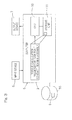
- a torque calculation method for the four point contact ball bearing assembly is performed by causing a computer 5, shown in Fig. 3 , to execute a torque calculation program 9 for the four point contact ball bearing assembly.
- the computer 5 is in the form of a personal computer and includes a central processing unit (CPU) 10 and a storage unit 11 such as, for example, a memory and is driven by a particular operation program.
- the computer 5 is electrically connected with an input device 6 such as, for example, a keyboard and/or a mouse and an output device 7 such as, for example, a display device such as, for example, a liquid crystal display device capable of displaying through a display screen, and/or a printer, or is provided with those devices as respective component parts of the computer 5.
- This computer 5 is also provided with a recording medium comprised of an external or built-in hard disc device 55 (the external device being shown in Fig. 3 ) and stores therein the torque calculation program 9 for the four point contact ball bearing assembly.
- the torque calculation program 9 may be stored in a recording medium such as, for example, CD-ROM and may be readable by the computer 5 through a CD-ROM interface of the computer 5.
- This torque calculation program 9 is deployed in a memory 11 at the time a torque calculating process is executed, and various program commands of the program 9 are executed by the central processing unit 10.
- a torque calculating device for the four point contact ball bearing assembly of which various function accomplishing sections are shown in Fig. 4 in the form of blocks, is constructed. The detail of the structure of such device will be described later.
- the torque calculation program 9 is a program executable by the computer 5, causes the computer to calculate the rotational torque that acts between the inner and outer rings of the four point contact ball bearing assembly and includes various procedures shown in Figs. 7A and 7B in the form of a flowchart.
- a calculation program 8 for calculating a contact pressure is also a program executable by the computer 5.
- the torque calculation method for the four point contact ball bearing assembly includes, as shown in the flowchart of Fig. 5A , a contact pressure calculation step V0 for calculating the contact pressure of each of the rolling elements, an individual torque calculation step V1, and a total sum calculation step V2.
- a contact pressure calculation step V0 for calculating the contact pressure of each of the rolling elements
- an individual torque calculation step V1 a rotational torque for each of the rolling elements in consideration of contact status.
- the total sum calculation step V2 the total sum of rotational torques T of the rolling elements calculated in the individual torque calculation step V1 is calculated and then determined as the rotational torque T0 that acts between the inner and outer rings.
- the step V0 referred to above is a sort of the preprocessing step.
- a coefficient C for each bearing that may be an object to be calculated is first determined (V0). Since the coefficient C is a value that varies depending on items of specification of the bearing assembly (such as the number and dimension of the rolling elements and geometric shape of each of the raceways), the coefficient C is determined for each of the bearing assemblies. It is to be noted that the wording "determined for each of the bearing assemblies" referred to above does not necessarily mean that it is determined for each of the bearing assemblies, but the same value of the coefficient C may be employed for the same model number, that is, for the bearing assembly of the same shape, dimension and material.
- the maximum contact pressures P 1 and P 2 of the partial raceways 1a and 1a in the inner ring 1, shown in Fig. 1 , and the rolling elements 3 are calculated.
- the calculation of the maximum contact pressures P 1 and P 2 will be explained later in connection with the establishment of the theory of a novel calculation equation that is used in the torque calculation in accordance with the present invention.
- contact pressures act on the two raceways 2a and 2a in the outer ring 2 in a manner similar to the contact pressures acting on the two partial raceways 1a and 1a in the inner ring 1, the maximum contract pressures P 1 and P 2 of the outer ring 2 may be calculated.
- the individual torque calculation step V1 includes the input step W1, a contact pressure sum calculation step W2, a four point contact ratio calculation step W3 and a contact ratio specific torque calculation step W4.
- the input step W1 is such as described above.
- a step U3 shown in Fig. 6 illustrates collectively the steps W1 to W3 in the flowchart of Fig. 5B .
- the "quadratic function of the four point contact ratio C f " referred to above may be chosen to be (1 + 36C f 2 ). Also, the constant I referred to above is generally considered preferably 10.
- the calculation is carried out in consideration of the contact condition representative of the extent of approximation to either one of the two point contact state and the four point contact state, and, therefore, the highly accurate value of the rotational torque, in which influences brought about by the difference in state of contact, that is a unique problem inherent in the four point contact ball bearing assembly, are taken into account, can be obtained.
- Figs. 7A and 7B illustrate the flowchart showing how the torque calculation program 9 for the four point contact ball bearing assembly is sequentially executed.
- This torque calculation program 9 is a program used to embody the torque calculation method shown in and described with particular reference to Figs. 5A and 5B , and steps R0 to R2 and steps S1 to S4 correspond respectively to the steps V0 to V2, shown in Fig. 5A , and the steps W1 to W4 shown in Fig. 5B , respectively, but will be explained for clarification purpose.
- the torque calculation program 9 is executable by a computer and is a program for calculating the rotational torque T0 acting between the inner and outer rings of the four point contact ball bearing assembly.
- This torque calculation program 9 includes;
- the individual torque calculation procedure R1 is made up of an input procedure S1, a contact pressure sum calculation procedure S2, a four point contact ratio calculation procedure S3 and a contact ratio specific torque calculation procedure S4.
- the input procedure S1 is a procedure to store in a storage region of the storage unit 11, shown in Figs. 3 and 4 , when the maximum contact pressures P 1 and P 2 between the two partial raceways in the inner ring and the rolling elements in each of the rolling elements and the coefficient C determined for each of the bearing assemblies are inputted.
- This inputting may be either done from the input device 3 or collectively done from a file.
- it may be a procedure to calculate by invoking the calculation procedure R0 and then to calculate, with a result of such calculation being inputted subsequently, in which case the calculation procedure R0 is executed subsequent to the input procedure S1.
- the "quadratic function of the four point contact ratio C f " referred to above may be chosen to be (1 + 36C f 2 ). Also, the constant I referred to above is generally considered preferably 10.
- This torque calculating device for the four point contact ball bearing assembly is a device for calculating the rotational torque T0 acting between the inner and outer rings of the four point contact ball bearing assembly and includes an individual torque calculation unit 13 for calculating the rotational torque T for each of the rolling elements, a total sum calculation unit 14 for determining the sum of the respective rotational torques T of all of the rolling elements, which sum is rendered to be the rotational torque T0 acting between the inner and outer rings, and a contact pressure calculation unit 12.
- the individual torque calculation unit 13 has a processing function that is performed in the individual torque calculation procedure R1 of the torque calculation program 9, shown in and described with particular reference to Figs.
- the contact pressure calculation unit 12 calculates the maximum contact pressures P 1 and P 2 between the two partial raceways in the inner ring and the rolling elements, respectively.
- the individual torque calculation unit 13 includes an input section 15, a contact pressure sum calculation section 16, a four point contact ratio calculation section 17 and a contact ratio specific torque calculation section 18.
- the input section 15, the contact pressure sum calculation section 16, the four point contact ratio calculation section 17 and the contact ratio specific torque calculation section 18 have respective processing functions performed in the input procedure S1, the contact pressure sum calculation procedure S2, the four point contact ratio calculation procedure S3 and the contact ratio specific torque calculation procedure S4 of the torque calculation program shown in and described with particular reference to Fig. 7B , but will now be explained for clarification purpose.
- the input section 15 stores in a storage region of the storage unit 11 when in each of the rolling elements the maximum contact pressures P 1 and P 2 between the two partial raceways in the inner ring and the rolling elements and the coefficient determined for each of the bearing assemblies are inputted. It is to be noted that this input section 15 may have a function of storing in a predetermined storage region when data, required to calculate the previously discussed maximum contact pressures P1 and P2 and the previously discussed coefficient C are inputted.
- the "quadratic function of the four point contact ratio C f " referred to above is preferably chosen to be (1 + 36C f 2 ). Also, the constant I referred to above is generally considered preferably 10.
- the total sum calculation unit 14 calculates the rotational torque ⁇ T of all of the tolling elements, using the equation (1) described in connection with the step U5 shown in Fig. 6 .
- the relation between the rotational torque and the conditions of contact of the rolling elements with the raceways has been examined.
- calculation of the rotational torque exhibited by one rolling element is performed. It is to be noted that the calculation of the rotational torque is to determine the rotational torque, which is induced in the raceway ring about a center axis, by constraining the respective positions of the inner and outer rings and then utilizing a center position, which has been determined from the balance between the force and the moment, and the velocities and directions of rotation and revolution of the rolling elements.
- the frictional force determined from a distribution of slides by determining a distribution of sliding velocities of the rolling elements and raceways within a contact ellipse in consideration of forces brought about from the four raceways as a result of elastic contact, and rotation and revolution of the balls. For the moment, the moment resulting from this frictional force is taken into account.
- a state (A) in which the outer ring is fixed as shown in Fig. 8 , the inner ring is applied a displacement in the radial direction as shown in state (B) of Fig. 8 and, at the same time, a displacement in the axial direction as shown in state (C) of Fig.
- the convergence calculation is carried out by changing the center position of the rolling elements and the velocities and directions of the rotation and the revolution so that all of the equations descriptive of the balance between the force and the moment of the rolling elements may be zero. As a result, the position of the rolling elements and others are outputted.
- a variable representative of the extent to which the four point contact state shifts to the two point contact state is defined here.
- the respective maximum contact pressures between the two partial raceways in the inner ring and the rolling elements are defined as P 1 and P 2 , and the ratio of the lower pressure relative to the higher pressure is defined as C f :
- C f min P 1 P 2 / max P 1 P 2 0 ⁇ C f ⁇ 1 wherein min(P 1 , P 2 ) represents one of P 1 and P 2 that is lower than the other of P 1 and P 2 and max(P 1 , P 2 ) represents one of P 1 and P 2 that is higher than the other of P 1 and P 2 .
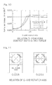
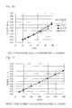
- the bearing torque relative to the four contact ratio C f is numerically calculated and the value of such torque divided by the contact pressure sum P S is then organized, such a relationship as shown in the chart in Fig. 10 is obtained.
- the torque which is divided by the contact pressure sum, has a tendency to change on the border of the four point contact ratio C f of 0.5.
- the four point contact ratio Cf is within the range of 0 to 0.5, the torque changes parabolically.
- the four point contact state is established, in which as shown in Fig. 11 , the axis of rotation of the rolling elements assumes a relation parallel to the bearing axis and a large distribution of slide velocity will occur within each of contact ellipses.
- the four point contact ratio C f assumes a value up to 0.5
- the axis of rotation of the rolling elements gradually changes from a condition similar to that in the angular contact ball bearing ( Fig. 11 ) to a position at which the axis of rotation assumes a relation parallel to the bearing axis. Since at this time, the distribution of slide velocity within the contact eclipse gradually increases and, therefore, it increases parabolically as shown in the chart of Fig. 10 .
- T Torque of one rolling element
- the parameter C represents the coefficient that depends on some items of the specification of the bearing assembly (such as geometric shapes of the rolling elements and the raceways), that is, for each of the bearing assemblies.
- a model bearing assembly of 500 mm in outer diameter was prepared and influences on by the rotational torque when each of the axial, radial and moment loads changes were endorsed.
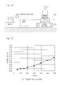
- the torque measuring method is verified with the use of the torque measuring device shown in Fig. 12 .
- Fig. 21 illustrates one example of a wind mill for electricity generation by wind power of a kind utilizing the four point contact ball bearing assembly which forms the object to be calculated.
- This wind mill 31 is of a structure, in which a nacelle 33 is mounted on a support structure 32 through a bearing assembly 42 for yawing for rotation in a horizontal plane and a main shaft 35 is rotatably supported within a casing 34 of the nacelle 33.
- One of opposite ends of the main shaft 35 which protrudes outwardly from the casing 34, has a blade assembly mounted thereon for rotation together therewith.
- the blade assembly is made up of a plurality of blades 36 each being a swirler and supported angularly adjustably by a respective bearing assembly 41.
- the opposite end of the main shaft 35 remote from the blade assembly is coupled with a speed increasing machine 37 having its output shaft 38 connected with a rotor shaft of a power generator 39.
- the above described bearing assembly 42 for yawing and the above described bearing assembly 41 for changing the angle of each of the blades 36 make use of a four point contact ball bearing assembly which will become a slewing bearing assembly (that is, a turntable bearing assembly).
- Those bearing assemblies 41 and 42 are subjected to the torque calculation according to the embodiment of the present invention.
- Fig. 22 illustrates on example of a CT scanner 50 which is a medical equipment and which makes use of a gantry as an inspecting unit and an X-ray tube for imaging and a detector and others are provided on a rotary unit 51.
- This rotary unit 51 is rotatably supported by a frame 53 through bearing assemblies 52.
- the bearing assemblies 52 for this CT scanner ⁇ gantry are subjected to the torque calculation according to the embodiment of the present invention.
- a recording medium, which is readable by a computer, according to the mode 1 is a computer readable recording medium, in which a program for causing the computer to execute a torque calculation method of any one embodiment of the present invention is recorded, which program includes:
- a recording medium which is readable by a computer, according to the mode 2 is a computer readable recording medium, in which a program for causing the computer to execute a torque calculation method of any one embodiment of the present invention is recorded, which program includes:
Landscapes
- Engineering & Computer Science (AREA)
- General Engineering & Computer Science (AREA)
- Mechanical Engineering (AREA)
- Physics & Mathematics (AREA)
- General Physics & Mathematics (AREA)
- Rolling Contact Bearings (AREA)
- Testing Of Devices, Machine Parts, Or Other Structures Thereof (AREA)
- Force Measurement Appropriate To Specific Purposes (AREA)
Abstract
Description
- This application is based on and claims Convention priority to Japanese patent application No.
2010-010259, filed January 20, 2010 - The present invention relates to a torque calculation method, a calculation device and a calculation program for calculating the rotational torque induced between inner and outer rings in a four point contact ball bearing, which are all applicable to the four point contact ball bearing assembly of a kind used in, for example, a slewing bearing assembly, used in a wind power generating equipment for yawing or a blade assembly, or a slewing bearing assembly used in medical equipments such as a CT scanner.
- In the bearing assembly for use in the wind power generating equipment or for medical equipment in, for example, the CT scanner, the single or double row four point contact ball bearing assembly has hitherto been employed. The slewing bearing assembly having the four point contact ball bearing structure has long been employed in applications such as a slewing unit in hydraulic excavators and cranes. Although in those applications, for a given rotational torque necessary to slew the bearing assembly, a drive device having a sufficient (torque) capacity has been employed, demands have now been increasing in the market to downsize, and promote the efficiency of, the wind power generating equipment and, therefore, it is an important key issue to accurately comprehend the rotational torque.
- In these days, the following equation for calculating the rotational torque in the slewing bearing assembly is currently employed:
-

wherein T represents the rotational torque [kN·m], µ represents the coefficient of friction, dm represents the ball PCD [m], and Poa represents the static equivalent axial load [kN]. - [Non-patent Document 1] Brochure available from Rothe Erde GmbH, entitled "Slewing Bearings", published in Germany in 2004.
- It has, however, been found that the conventional calculation equation referred to above has some problems. Specifically, according to the definition of the static equivalent axial load Poa, the foregoing equation applies where the maximum rolling element load equally acts on all of the rolling elements, but in practice, however, individual rolling element loads differ from each other because of influences brought about by, for example, a radial load and/or a moment load. Also, it is impossible to take into account influences brought about by the difference in state of contact (two point contact or four point contact), which is a unique problem inherent in the four point contact ball bearing assembly.
- In view of the foregoing, the present invention has for its object to provide a torque calculation method, a calculation device and a calculation program for a four point contact ball bearing assembly, which are effective to determine the value of the rotational torque with high accuracy in consideration of the influences brought about by the difference in state of contact, which is a problem peculiar to the four point contact ball bearing assembly.
- To summarize the present invention, the torque calculation method for a four point contact ball bearing assembly designed in accordance with the present invention is to calculate the rotational torque for each of the rolling elements with the contact condition taken into account and then to determine the sum thereof to render it to be the rotational torque.
- More specifically, this torque calculation method for calculating a rotational torque acting between inner and outer rings of a four point contact ball bearing assembly, which method comprises:
- an individual torque calculation step for calculating a rotational torque T for each of rolling elements; and
- a total sum calculation step for calculating the sum of respective rotational torques T of all of the rolling elements to determine the resultant sum to be the rotational torque T0 acting between the inner and outer rings;
- in which in the individual torque calculation step, calculation is made using data on a contact condition representative of an extent of approximation to either one of a two point contact state and a four point contact state.
- According to this torque calculation method, since the calculation is made with the contact condition, which is representative of the extent of approximation to either one of the two point contact state and the four point contact state, taken into consideration, the value of a highly accurate rotational torque can be determined in consideration of influences brought about by the difference in contact condition which has been a problem peculiar to the four point contact ball bearing assembly.
- In the practice of this torque calculation method of one embodiment of the present invention, as information containing the data on the contact condition, using the respective maximum contact pressures P1 and P2 between two raceways, which form respective raceways in an inner ring or an outer ring, and rolling elements, the maximum contact pressure sum PS defined for those two maximum contact pressures P1 and P2 to be represented by a single parameter us determined from the two maximum contact pressures P1 and P2 according to a predetermined equation, and using, with respect to the four contact ratio Cf, which is the ratio of the lower pressure relative to the higher pressure and which is determined by the following equation;

wherein min(P1, P2) represents one of P1 and P2 that is lower than the other of P1 and P2 and max(P1, P2) represents one of P1 and P2 that is higher than the other of P1 and P2, predetermined calculation equations that are divided into two on the boundary of Cf = 0.5, the rotational torque T for each of the rolling elements may be calculated from the contact pressure sum PS. In this case, the two partial raceways means raceway portions positioned on respective side of the bottom of the raceway, that is, the minimum diametric portion of the raceway in the inner ring or the maximum diametric portion of the raceway in the outer ring in a direction axially of the bearing assembly and, where either the inner ring or the outer ring is of a unitary element that is not split, those two partial raceways form a raceway comprised of a single continuous raceway. - As compared with the case in which the rotational torque is calculated directly from the two maximum contact pressures P1 and P2 the use of the contact pressure sum PS referred to above is effective to allow the rotational torque to be calculated from each of the rolling elements through a simple mathematic calculation. On the boarder of the four point contact ratio Cf being 0.5, the contact pressure sum PS is such that the tendency to change the torque divided by the contact pressure sum PS makes a sudden change. When the four point contact ratio Cf is greater than 0.5, the torque becomes substantially constant and, as compared with the case with the four point contact ratio Cf being zero, such torque will become 8 to 12 times. When the four point contact ratio Cf is within the range of 0 to 0.5, it changes parabolically. For this reason, with the boarder of the four point contact ratio Cf being 0.5, by calculating the rotational torque T for each of the rolling elements from the contact pressure sum PS with the use of the predetermined calculation equation that has been dived into two, the rotational torque T can be accurately and easily calculated.
- In the torque calculation method of one embodiment of the present invention, an equation necessary to determine the contact pressure sum PS may be as follows:

This is because the fourth power of the contact pressure is considered proportional to the rotational torque. - In the torque calculation method of one embodiment of the present invention, the rotational torque, which is applicable when the four point contact ratio Cf is greater than 0.5 while the rotational torque when the four contact ratio Cf is zero is T, may be of a value multiplied by a predetermined multiplication number that is within the range of 8 to 10. Also, the rotational torque T applicable when the four point contact ratio Cf may be within the range of 0 to 0.5 is of a value complemented by a quadratic function of the four point contact ratio Cf.
- As hereinabove described, the torque will become substantially constant when the four point contact ratio Cf is greater than 0.5, and, as compared with the case in which the four point contact ratio Cf is zero, it will become 8 to 12 times because, when the four point contact ratio Cf is within the range of 0 to 0.5, it will change parabolically.
- In the torque calculation method of one embodiment of the present invention, the rotational torque T may be calculated according to the following equations, using the four point contact ratio Cf, the contact pressure sum PS and the coefficient C determined for each bearing assembly;
when 0 ≤ Cf < 0.5,
and when 0.5≤Cf≤1.0,
- The parameter C referred to above represents the coefficient that depends on some items of the specification of the bearing assembly (such as the number, dimensions and geometric shapes of the rolling elements) and, therefore, it is determined for each of the bearing assemblies. It is to be noted that the wording "determined for each of the bearing assemblies" referred to above does not necessarily means that it is determined for each of the bearing assemblies, but the same value and the same coefficient C may be employed for the same model number, that is, for the bearing assembly of the same shape, dimension and material.
- In the torque calculation method of one embodiment of the present invention, the torque calculation method may be a method executed by the use of a computer, which method includes:
- in addition to the individual torque calculation step and the total sum calculation step;
- a step of calculating the contact pressure for each of the rolling elements;
- the individual torque calculation step including an input step for inputting and storing in a storage region, a load (Fr(Fx, Fy), Fa, M(Mx, My)), acting on a bearing assembly, and a coefficient C determined for each of bearing assemblies;
- a contact pressure sum calculation step for calculating the contact pressure sum PS, defined for the respective maximum contact pressures P1 and P2 between two raceways in an inner ring or an outer ring and rolling elements to be represented by a single parameter in the individual rolling elements, determined in the calculation step, is determined by the following equation:

- a four point contact ratio calculation step for calculating a four point contact ratio Cf, which is the ratio of the lower pressure relative to the higher pressure that is determined by the following equation:

wherein min(P1, P2) represents one of P1 and P2 that is lower than the other of P1 and P2 and max(P1, P2) represents one of P1 and P2 that is higher than the other of P1 and P2; and - a contact ratio specific torque calculation step for calculating the rotational torque T according to the following equations, using the contact pressure total sum PS, the four point contact ratio Cf and the coefficient C;

when 0 ≤ Cf < 0.5, and
when 0.5≤Cf≤1.0. - In the torque calculation method of one embodiment of the present invention, the torque calculation method is a method executed with the use of a computer, in which the individual torque calculation step includes an input step for inputting and storing in a storage region, respective maximum contact pressures P1 and P2 between two partial raceways, forming raceways in an inner ring or an outer ring, and rolling elements in the individual rolling elements, and a coefficient C determined for each of bearing assemblies;
- a contact pressure sum calculation step for calculating the contact pressure sum PS, defined for the respective maximum contact pressures P1 and P2 to be represented by a single parameter, is determined by the following equation:

- a four point contact ratio calculation step for calculating a four point contact ratio Cf, which is the ratio of the lower pressure relative to the higher pressure that is determined by the following equation:

wherein min(P1, P2) represents one of P1 and P2 that is lower than the other of P1 and P2 and max(P1, P2) represents one of P1 and P2 that is higher than the other of P1 and P2; and - a contact ratio specific torque calculation step for calculating the rotational torque T according to the following equations, using the contact pressure total sum PS, the four point contact ratio Cf and the coefficient C;

when 0 ≤ Cf < 0.5, and
when 0.5 ≤ Cf ≤ 1.0. - In the torque calculation method of one embodiment of the present invention, the method may be applied to a four point contact ball bearing assembly that is used at a low speed of dn value = not higher than 30,000. In the case of the bearing assembly having the low dn value, the calculation according to the method of the present invention is further effective.
- The torque calculation method of one embodiment of the present invention may be applied not only to a single row four point contact ball bearing assembly, but also to a double row four point contact ball bearing assembly.
- The torque calculation method of the present invention may be applied to not only to a bearing assembly for angularly adjustably supporting a blade assembly of a wind mill, but also to a bearing assembly in a wind mill for yawing and to a bearing assembly for medical equipment.
- The torque calculating device of the present invention is a device for executing the torque calculation method referred to hereinabove, which device includes:
- a contact pressure calculation unit for calculating the contact pressure for each of the rolling elements;
- an individual torque calculation unit for executing the individual torque calculation step, and
- a total sum calculation unit for executing the total sum calculation step; in which the individual torque calculation unit includes:
- an input section for inputting and storing in a storage region, a load (Fr(Fx, Fy), Fa, M(Mx, My)), acting on a bearing assembly, and a coefficient C determined for each of bearing assemblies;
- a contact pressure sum calculation section for calculating the contact pressure sum PS, defined for the respective maximum contact pressures P1 and P2 between two raceways in an inner ring or an outer ring and rolling elements to be represented by a single parameter in the individual rolling elements, determined in the calculation procedure, is determined by the following equation:

- a four point contact ratio calculation section for calculating a four point contact ratio Cf, which is the ratio of the lower pressure relative to the higher pressure that is determined by the following equation:

wherein min(P1, P2) represents one of P1 and P2 that is lower than the other of P1 and P2 and max(P1, P2) represents one of P1 and P2 that is higher than the other of P1 and P2; and - a contact ratio specific torque calculation section for calculating the rotational torque T according to the following equations, using the contact pressure total sum PS, the four point contact ratio Cf and the coefficient C;

when 0 ≤ Cf < 0.5, and
when 0.5 ≤ Cf ≤1.0. - The torque calculating device of one embodiment of the present invention is a device for executing the torque calculation method referred to hereinabove, which device includes:
- an individual torque calculation unit for executing the individual torque calculation step; and
- a total sum calculation unit for executing the total sum calculation step; in which the individual torque calculation unit for storing in a storage region, when the respective maximum contact pressures P1 and P2 between two partial raceways, forming raceways in an inner ring or an outer ring, and rolling elements in the individual rolling elements, and a coefficient C determined for each of bearing assemblies are inputted;
- a contact pressure sum calculation section for calculating the contact pressure sum PS, defined for the respective maximum contact pressures P1 and P2 to be represented by a single parameter is determined by the following equation:

- a four point contact ratio calculation procedure for calculating a four point contact ratio Cf, which is the ratio of the lower pressure relative to the higher pressure that is determined by the following equation:

wherein min(P1, P2) represents one of P1 and P2 that is lower than the other of P1 and P2 and max(P1, P2) represents one of P1 and P2 that is higher than the other of P1 and P2; and - a contact ratio specific torque calculation section for calculating the rotational torque T according to the following equations, using the contact pressure total sum PS, the four point contact ratio Cf and the coefficient C;

when 0 ≤ Cf < 0.5, and
when 0.5 ≤ Cf ≤ 1.0. - In the torque calculating device of one embodiment of the present invention, the calculation of the rotational torque in the contact ratio specific torque calculation section, when 0 ≤ Cf < 0.5, may be carried out according to the following equation:

- The torque calculation program of the present invention is a program for causing the computer to execute the torque calculation method referred to hereinabove, which program includes:
- a contact pressure calculation procedure for calculating the contact pressure for each of the rolling elements;
- an individual torque calculation procedure for executing the individual torque calculation step, and
- a total sum calculation procedure for executing the total sum calculation step;
- an input procedure for inputting and storing in a storage region, a load (Fr(Fx, Fy), Fa, M(Mx, My)), acting on a bearing assembly, and a coefficient C determined for each of bearing assemblies;
- a contact pressure sum calculation procedure for calculating the contact pressure sum PS, defined for the respective maximum contact pressures P1 and P2 between two raceways in an inner ring or an outer ring and rolling elements to be represented by a single parameter in the individual rolling elements, determined in the calculation procedure, is determined by the following equation:

- a four point contact ratio calculation procedure for calculating a four point contact ratio Cf, which is the ratio of the lower pressure relative to the higher pressure that is determined by the following equation:

wherein min(P1, P2) represents one of P1 and P2 that is lower than the other of P1 and P2 and max(P1, P2) represents one of P1 and P2 that is higher than the other of P1 and P2; and - a contact ratio specific torque calculation section for calculating the rotational torque T according to the following equations, using the contact pressure total sum PS, the four point contact ratio Cf and the coefficient C;

when 0 ≤ Cf < 0.5, and
when 0.5 ≤ Cf ≤ 1.0. - The torque calculation program of the present invention is a program for causing the computer to execute the torque calculation method referred to hereinabove, which program includes:
- an individual torque calculation procedure for executing the individual torque calculation step; and
- a total sum calculation procedure for executing the total sum calculation step; and
- an input procedure for inputting and storing in a storage region, a load (Fr(Fx, Fy), Fa, M(Mx, My)), acting on a bearing assembly, and a coefficient C determined for each of bearing assemblies;
- a four point contact ratio calculation procedure for calculating a four point contact ratio Cf, which is the ratio of the lower pressure relative to the higher pressure that is determined by the following equation:

wherein min(P1, P2) represents one of P1 and P2 that is lower than the other of P1 and P2 and max(P1, P2) represents one of P1 and P2 that is higher than the other of P1 and P2; and - a contact ratio specific torque calculation section for calculating the rotational torque T according to the following equations, using the contact pressure total sum PS, the four point contact ratio Cf and the coefficient C;

when 0 ≤ Cf < 0.5, and
when 0.5 ≤ Cf ≤ 1.0. - In each of the calculation programs referred to above, the calculation of the rotational torque in the contact ratio specific torque calculation section, when 0 ≤ Cf < 0.5, may be carried out according to the following equation:

- In any event, the present invention will become more clearly understood from the following description of embodiments thereof, when taken in conjunction with the accompanying drawings. However, the embodiments and the drawings are given only for the purpose of illustration and explanation, and are not to be taken as limiting the scope of the present invention in any way whatsoever, which scope is to be determined by the appended claims. In the accompanying drawings, like reference numerals are used to denote like parts throughout the several views, and:
-
Fig. 1 is a fragmentary longitudinal sectional view showing one example of a four point contact ball bearing assembly that is an object to be calculated by a torque calculation method, device and program of the present invention for the four point contact ball bearing assembly; -
Fig. 2 is a fragmentary longitudinal sectional view showing one example of a double row four point contact ball bearing assembly; -
Fig. 3 is a block diagram showing an example of relation between programs for the torque calculating device and a computer, both used in the practice of the torque calculation method of the present invention; -
Fig. 4 is a block diagram showing a conceptual construction of the torque calculating device for the four point contact ball bearing assembly according to a embodiment of the present invention; -
Fig. 5A is a flowchart showing the torque calculation method for the four point contact ball bearing assembly according to the embodiment of the present invention; -
Fig. 5B is a flowchart showing specific contents of an individual torque calculation step V1; -
Fig. 6 is a flowchart that contains the torque calculation method and a preprocessing step; -
Fig. 7A is a flowchart showing the torque calculation program for the four point contact ball bearing assembly according to the embodiment of the present invention; -
Fig. 7B is a flowchart showing a total sum calculating method; -
Fig. 8 is an explanatory diagram used to explain a study method that leads to the theory of the torque calculation method of the present invention, in which (A) illustrates a state in which an outer ring is fixed, (B) illustrates a state in which an inner ring is displaced in a radial direction, and (C) illustrates a state in which the inner ring is displaced in an axial direction; -
Fig. 9 is an explanatory diagram used to explain respective definitions of the maximum contact pressures P1 and P2; -
Fig. 10 is a chart showing the relation between a four point contact ratio Cf and a torque; -
Fig. 11 is an explanatory diagram showing the relation between the four point contact ratio Cf and a rotation shaft; -
Fig. 12 is an explanatory diagram showing a conceptual construction of a torque measuring device used during a series of tests conducted to study the torque calculation method of the present invention; -
Fig. 13 is a chart showing a result of the tests (at the time of Fa loading); -
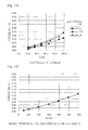
Fig. 14 is a chart showing a result of the tests (at the time of Fr loading); -
Fig. 15 is a chart showing a result of calculation (at the time of the Fa loading) according to the embodiment of the present invention; -
Fig. 16 is a chart showing a result of calculation (at the time of the Fr loading) according to the embodiment of the present invention; -
Fig. 17 is a chart showing a result of calculation (at the time of Fa loading) according to the conventional (currently employed) calculation equation; -
Fig. 18 is a chart showing a result of calculation (at the time of Fr loading) according to the conventional (currently employed) calculation equation; -
Fig. 19 is a chart showing a result of tests conducted to determine the relation between a load and a torque; -
Fig. 20 is a chart showing the relation between the load and the torque, which will become a result of calculation of the calculation equation according to the embodiment of the present invention; -
Fig. 21 is an explanatory diagram showing one example of a wind power generating equipment utilizing the four point contact ball bearing assembly which is the object to be calculated according to the embodiment of the present invention; -
Fig. 22 is an explanatory diagram showing one example of a medical equipment utilizing the four point contact ball bearing assembly which is the object to be calculated according to the embodiment of the present invention; and -
Fig. 23 is an explanatory diagram showing a two point contact state and a four point contact state in the four point contact ball bearing assembly. - One embodiment of the present invention will be described in detail with particular reference to the accompanying drawings. In particular,
Fig. 1 illustrates one example of a four point contact ball bearing assembly which will become an object to be calculated. This four point contact ball bearing assembly is an example of a single row bearing assembly of a structure in which groove shapedpartial raceways inner ring 1 and anouter ring 2, respectively,contact rolling elements 3 in the form of balls at four points and in which a radial load and an axial load acting in both directions opposite to each other can be loaded. The twopartial raceways inner ring 1 are adjoined with each other in a direction axially of the bearing assembly to thereby define a single raceway that forms a raceway for therolling elements 3. Theinner ring 1, although shown as comprised of two inner ring halves 1A and 1A in the instance as shown, may be an unitary ring that is not divided.Fig. 2 illustrates an example of a dual row four contact ball bearing assembly, in which each of theinner ring 1 and theouter ring 2 is comprised of an unitary ring. Even the example shown inFig. 2 may become an object to be calculated in accordance with the present invention. - A torque calculation method for the four point contact ball bearing assembly is performed by causing a computer 5, shown in
Fig. 3 , to execute atorque calculation program 9 for the four point contact ball bearing assembly. The computer 5 is in the form of a personal computer and includes a central processing unit (CPU) 10 and astorage unit 11 such as, for example, a memory and is driven by a particular operation program. The computer 5 is electrically connected with aninput device 6 such as, for example, a keyboard and/or a mouse and an output device 7 such as, for example, a display device such as, for example, a liquid crystal display device capable of displaying through a display screen, and/or a printer, or is provided with those devices as respective component parts of the computer 5. This computer 5 is also provided with a recording medium comprised of an external or built-in hard disc device 55 (the external device being shown inFig. 3 ) and stores therein thetorque calculation program 9 for the four point contact ball bearing assembly. Instead thereof, thetorque calculation program 9 may be stored in a recording medium such as, for example, CD-ROM and may be readable by the computer 5 through a CD-ROM interface of the computer 5. Thistorque calculation program 9 is deployed in amemory 11 at the time a torque calculating process is executed, and various program commands of theprogram 9 are executed by thecentral processing unit 10. When thetorque calculation program 9 for the four point contact ball bearing assembly is read in and executed by the computer 5 in the manner described above, a torque calculating device for the four point contact ball bearing assembly, of which various function accomplishing sections are shown inFig. 4 in the form of blocks, is constructed. The detail of the structure of such device will be described later. - The
torque calculation program 9 is a program executable by the computer 5, causes the computer to calculate the rotational torque that acts between the inner and outer rings of the four point contact ball bearing assembly and includes various procedures shown inFigs. 7A and 7B in the form of a flowchart. A calculation program 8 for calculating a contact pressure is also a program executable by the computer 5. - The torque calculation method for the four point contact ball bearing assembly includes, as shown in the flowchart of
Fig. 5A , a contact pressure calculation step V0 for calculating the contact pressure of each of the rolling elements, an individual torque calculation step V1, and a total sum calculation step V2. In the individual torque calculation step V1, a rotational torque for each of the rolling elements in consideration of contact status. In the total sum calculation step V2, the total sum of rotational torques T of the rolling elements calculated in the individual torque calculation step V1 is calculated and then determined as the rotational torque T0 that acts between the inner and outer rings. The step V0 referred to above is a sort of the preprocessing step. - Specific contents of the individual torque calculation step V1 are shown in the flowchart of
Fig. 5B and contents of the various steps are shown in the flowchart ofFig. 6 together with calculation equations. - As shown in the flowchart of
Fig. 6 , in the practice of this method, a coefficient C for each bearing that may be an object to be calculated is first determined (V0). Since the coefficient C is a value that varies depending on items of specification of the bearing assembly (such as the number and dimension of the rolling elements and geometric shape of each of the raceways), the coefficient C is determined for each of the bearing assemblies. It is to be noted that the wording "determined for each of the bearing assemblies" referred to above does not necessarily mean that it is determined for each of the bearing assemblies, but the same value of the coefficient C may be employed for the same model number, that is, for the bearing assembly of the same shape, dimension and material. Thereafter, under a load condition to be studied, the maximum contact pressures P1 and P2 of thepartial raceways inner ring 1, shown inFig. 1 , and the rollingelements 3 are calculated. The calculation of the maximum contact pressures P1 and P2 will be explained later in connection with the establishment of the theory of a novel calculation equation that is used in the torque calculation in accordance with the present invention. Also, Since contact pressures act on the tworaceways outer ring 2 in a manner similar to the contact pressures acting on the twopartial raceways inner ring 1, the maximum contract pressures P1 and P2 of theouter ring 2 may be calculated. - In the practice of the individual torque calculation step V1, the maximum contact pressures P1 and P2 between the two partial raceways in the inner ring and the rolling elements in the individual rolling elements so calculated, respectively, and the coefficient C determined for each of the bearing assemblies are inputted at an input step W1 shown in
Fig. 5B . - The individual torque calculation step V1 includes the input step W1, a contact pressure sum calculation step W2, a four point contact ratio calculation step W3 and a contact ratio specific torque calculation step W4. The input step W1 is such as described above.
- The contact pressure sum calculation step W2 is a step, in which the contact pressure sum PS defined for the above described two maximum contact pressures P1 and P2 to be represented by a single parameter is determined by the following equation:

- The four point contact ratio calculation step W3 is a step, in which the four point contact ratio Cf, which is the ratio of the lower pressure relative to the higher pressure that is determined by the following equation:

wherein min(P1, P2) represents one of P1 and P2 that is lower than the other of P1 and P2 and max(P1, P2) represents one of P1 and P2 that is higher than the other of P1 and P2. - A step U3 shown in
Fig. 6 illustrates collectively the steps W1 to W3 in the flowchart ofFig. 5B . - Referring to
Fig. 5B , the contact ratio specific torque calculation step W4 (a step U4 shown inFig. 6 ) is a step, in which the rotational torque T is calculated according to the following equations, using the contact pressure total sum PS, the four point contact ratio Cf and the coefficient C:
when 0 ≤ Cf < 0.5, and
when 0.5 ≤ Cf ≤ 1.0. - The "quadratic function of the four point contact ratio Cf" referred to above may be chosen to be (1 + 36Cf 2). Also, the constant I referred to above is generally considered preferably 10.
- Accordingly, it is preferred that when more specifically 0 ≤ Cf < 0.5,

and when 0.5 ≤ Cf ≤ 1,
- In the total sum calculation step V2 shown in
Fig. 5A (a step U5 shown inFig. 6 ), when expressed in terms of a mathematical expression, the rotational torque ΣT of all of the tolling elements, which is obtained from the following equation (1), is calculated. It is to be noted that the parameter Z in the equation (1) represents the number of the rolling elements.
- According to the torque calculation method for the four point contact ball bearing assembly according to this embodiment, the calculation is carried out in consideration of the contact condition representative of the extent of approximation to either one of the two point contact state and the four point contact state, and, therefore, the highly accurate value of the rotational torque, in which influences brought about by the difference in state of contact, that is a unique problem inherent in the four point contact ball bearing assembly, are taken into account, can be obtained.
- The theory, which leads to the above described torque calculation method, and the result of studies will be described later.
-
Figs. 7A and 7B illustrate the flowchart showing how thetorque calculation program 9 for the four point contact ball bearing assembly is sequentially executed. Thistorque calculation program 9 is a program used to embody the torque calculation method shown in and described with particular reference toFigs. 5A and 5B , and steps R0 to R2 and steps S1 to S4 correspond respectively to the steps V0 to V2, shown inFig. 5A , and the steps W1 to W4 shown inFig. 5B , respectively, but will be explained for clarification purpose. - The
torque calculation program 9 is executable by a computer and is a program for calculating the rotational torque T0 acting between the inner and outer rings of the four point contact ball bearing assembly. Thistorque calculation program 9 includes; - an individual torque calculation procedure R1 for calculating the rotational torque T for each of the rolling elements, and
- a total sum calculation procedure R2 for determining the sum of the respective rotational torques T of all of the rolling elements, which sum is rendered to be the rotational torque T0 acting between the inner and outer rings. It is, however, to be noted that a procedure R0 for calculating the contact pressure of each of the rolling elements may be provided either as a part of the torque calculation program or as a step separate from the
torque calculation program 9. - The individual torque calculation procedure R1 is made up of an input procedure S1, a contact pressure sum calculation procedure S2, a four point contact ratio calculation procedure S3 and a contact ratio specific torque calculation procedure S4.
- The input procedure S1 is a procedure to store in a storage region of the
storage unit 11, shown inFigs. 3 and4 , when the maximum contact pressures P1 and P2 between the two partial raceways in the inner ring and the rolling elements in each of the rolling elements and the coefficient C determined for each of the bearing assemblies are inputted. This inputting may be either done from theinput device 3 or collectively done from a file. Also, it may be a procedure to calculate by invoking the calculation procedure R0 and then to calculate, with a result of such calculation being inputted subsequently, in which case the calculation procedure R0 is executed subsequent to the input procedure S1. - The contact pressure sum calculation procedure S2 is a procedure to determine by the following equation the contact pressure sum PS defined for the two maximum contact pressures P1 and P2, so inputted as described above, to be represented by a single parameter:

- The four point contact ratio calculation procedure S3 is a procedure to calculate the four point contact ratio Cf, which is the ratio of the lower pressure relative to the higher pressure that is determined by the following equation:

wherein min(P1, P2) represents one of P1 and P2 that is lower than the other of P1 and P2 and max(P1, P2) represents one of P1 and P2 that is higher than the other of P1 and P2. - The contact ratio specific torque calculation procedure S4 is a procedure to calculate the rotational torque T according to the following equations, using the contact pressure total sum PS, the four point contact ratio Cf and the coefficient C;:

when 0 ≤ Cf < 0.5, and
when 0.5 ≤ Cf ≤ 1. - The "quadratic function of the four point contact ratio Cf" referred to above may be chosen to be (1 + 36Cf 2). Also, the constant I referred to above is generally considered preferably 10.
- Accordingly, it is preferred that when more specifically 0 ≤ Cf < 0.5,

and when 0.5 <Cf ≤ 1.0,
- In the total sum calculation procedure R2 shown in
Fig. 7A , using the equation (1) described in connection with the step U5 shown inFig. 6 , the rotational torque ΣT of all of the rolling elements is calculated. - With reference to
Fig. 4 , the torque calculating device for the four point contact ball bearing assembly will now be described. This torque calculating device for the four point contact ball bearing assembly is a device for calculating the rotational torque T0 acting between the inner and outer rings of the four point contact ball bearing assembly and includes an individualtorque calculation unit 13 for calculating the rotational torque T for each of the rolling elements, a totalsum calculation unit 14 for determining the sum of the respective rotational torques T of all of the rolling elements, which sum is rendered to be the rotational torque T0 acting between the inner and outer rings, and a contactpressure calculation unit 12. The individualtorque calculation unit 13 has a processing function that is performed in the individual torque calculation procedure R1 of thetorque calculation program 9, shown in and described with particular reference toFigs. 7A and 7B , and the totalsum calculation unit 14 has a processing function that is performed in the total sum calculation procedure R2 of thetorque calculation program 9. The contactpressure calculation unit 12 calculates the maximum contact pressures P1 and P2 between the two partial raceways in the inner ring and the rolling elements, respectively. - The individual
torque calculation unit 13 includes aninput section 15, a contact pressuresum calculation section 16, a four point contactratio calculation section 17 and a contact ratio specifictorque calculation section 18. Theinput section 15, the contact pressuresum calculation section 16, the four point contactratio calculation section 17 and the contact ratio specifictorque calculation section 18 have respective processing functions performed in the input procedure S1, the contact pressure sum calculation procedure S2, the four point contact ratio calculation procedure S3 and the contact ratio specific torque calculation procedure S4 of the torque calculation program shown in and described with particular reference toFig. 7B , but will now be explained for clarification purpose. - The
input section 15 stores in a storage region of thestorage unit 11 when in each of the rolling elements the maximum contact pressures P1 and P2 between the two partial raceways in the inner ring and the rolling elements and the coefficient determined for each of the bearing assemblies are inputted. It is to be noted that thisinput section 15 may have a function of storing in a predetermined storage region when data, required to calculate the previously discussed maximum contact pressures P1 and P2 and the previously discussed coefficient C are inputted. - The contact pressure
sum calculation section 12 determines the contact pressure sum PS defined for the two maximum contact pressures P1 and P2, so inputted as described above, to be represented by a single parameter is determined by the following equation:
- The four point contact
ratio calculation section 17 calculates the four point contact ratio Cf, which is the ratio of the lower pressure relative to the higher pressure that is determined by the following equation:
wherein min(P1, P2) represents one of P1 and P2 that is lower than the other of P1 and P2 and max(P1, P2) represents one of P1 and P2 that is higher than the other of P1 and P2. - The contact ratio specific
torque calculation section 18 calculates the rotational torque T according to the following equations, using the contact pressure total sum PS, the four point contact ratio Cf and the coefficient C;:
when 0 ≤ Cf < 0.5, and
when 0.5 ≤ Cf ≤ 1.0. - The "quadratic function of the four point contact ratio Cf" referred to above is preferably chosen to be (1 + 36Cf 2). Also, the constant I referred to above is generally considered preferably 10.
- Accordingly, it is preferred that when more specifically 0 ≤ Cf < 0.5,

and when 0.5 ≤ Cf ≤1.0,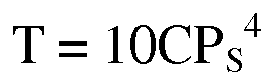
- The total
sum calculation unit 14 calculates the rotational torque ΣT of all of the tolling elements, using the equation (1) described in connection with the step U5 shown inFig. 6 . - The establishment of the theory of calculating the torque by means of the novel calculation equation that is employed in the practice of the foregoing embodiment of the present invention will now be explained.
- Using a numerical analysis tool developed by the applicant, the relation between the rotational torque and the conditions of contact of the rolling elements with the raceways has been examined. With the analysis tool referred to above, calculation of the rotational torque exhibited by one rolling element is performed. It is to be noted that the calculation of the rotational torque is to determine the rotational torque, which is induced in the raceway ring about a center axis, by constraining the respective positions of the inner and outer rings and then utilizing a center position, which has been determined from the balance between the force and the moment, and the velocities and directions of rotation and revolution of the rolling elements. For the force acting on the rolling elements, the frictional force determined from a distribution of slides by determining a distribution of sliding velocities of the rolling elements and raceways within a contact ellipse in consideration of forces brought about from the four raceways as a result of elastic contact, and rotation and revolution of the balls. For the moment, the moment resulting from this frictional force is taken into account. While in a state (A), in which the outer ring is fixed as shown in
Fig. 8 , the inner ring is applied a displacement in the radial direction as shown in state (B) ofFig. 8 and, at the same time, a displacement in the axial direction as shown in state (C) ofFig. 8 , the convergence calculation is carried out by changing the center position of the rolling elements and the velocities and directions of the rotation and the revolution so that all of the equations descriptive of the balance between the force and the moment of the rolling elements may be zero. As a result, the position of the rolling elements and others are outputted. - It is to be noted that a factor that is taken into account in connection with the bearing torque is limited to the friction occurring as a result of a slide within contact regions. Also, the coefficient of this friction is assumed based on the boundary lubrication and is employed in the form as associated with a function of only the sliding velocity. Although the torque calculation of the bearing assembly in its entirety is technically possible by applying the convergence calculation of the forces and moments of the rolling elements to all of the rolling elements, this involves a substantial amount of time required to finish the torque calculation or the condition tends to occur in which convergence is hard to accomplish, and, therefore, the calculating system of the present invention is effective to provide a stable result within a short length of time.
- A variable representative of the extent to which the four point contact state shifts to the two point contact state is defined here. The respective maximum contact pressures between the two partial raceways in the inner ring and the rolling elements are defined as P1 and P2, and the ratio of the lower pressure relative to the higher pressure is defined as Cf:

wherein min(P1, P2) represents one of P1 and P2 that is lower than the other of P1 and P2 and max(P1, P2) represents one of P1 and P2 that is higher than the other of P1 and P2. - Accordingly, when Cf = 0, the perfect two point contact state occurs, and when Cf = 1, the four point contact state of P1 = P2 occurs as is the case when the net radial load is loaded.
- Also, for simplification of the torque calculation equation in the description that follows, the contact pressure sum PS for representing the contact pressures of P1 and P2 by a single parameter is defined as follows:

- This is because in view of the relation discussed subsequently, the fourth power of the contact pressure is considered proportional to the rotational torque.


in which P represents the contact pressure, Q represents the rolling element load and T represents the rotational torque. - If in one rolling element, the bearing torque relative to the four contact ratio Cf is numerically calculated and the value of such torque divided by the contact pressure sum PS is then organized, such a relationship as shown in the chart in
Fig. 10 is obtained. It will readily be understood that the torque, which is divided by the contact pressure sum, has a tendency to change on the border of the four point contact ratio Cf of 0.5. The torque is substantially constant when the four point contact ratio Cf exceeds 0.5 and results in the value that is about ten times as compared when Cf = 0. In addition, when the four point contact ratio Cf is within the range of 0 to 0.5, the torque changes parabolically. - When the four point contact ratio Cf exceeds 0.5, the four point contact state is established, in which as shown in
Fig. 11 , the axis of rotation of the rolling elements assumes a relation parallel to the bearing axis and a large distribution of slide velocity will occur within each of contact ellipses. On the other hand, when the four point contact ratio Cf assumes a value up to 0.5, the axis of rotation of the rolling elements gradually changes from a condition similar to that in the angular contact ball bearing (Fig. 11 ) to a position at which the axis of rotation assumes a relation parallel to the bearing axis. Since at this time, the distribution of slide velocity within the contact eclipse gradually increases and, therefore, it increases parabolically as shown in the chart ofFig. 10 . - From these results, the new torque calculation equation [T: Torque of one rolling element] is fixed as follows.

and
- In those equations, the parameter C represents the coefficient that depends on some items of the specification of the bearing assembly (such as geometric shapes of the rolling elements and the raceways), that is, for each of the bearing assemblies.
- Hereinafter, the result of examination conducted to determine the validity of the foregoing equations will be discussed.
- In order to ascertain the validity of the novel calculation equation, a model bearing assembly of 500 mm in outer diameter was prepared and influences on by the rotational torque when each of the axial, radial and moment loads changes were endorsed. The torque measuring method is verified with the use of the torque measuring device shown in
Fig. 12 . In this testing machine, the axial load can be loaded in the form of the net axial load and the moment load is generated by loading the radial load at respective positions (shown by h inFig. 12 ) spaced h = 0.5, 0.75 and 1.0 meters in the axial direction from the bearing center. -
Bearing Assembly: Model bearing assembly (Double row four point contact ball bearing assembly) Dimensions: ϕ335 (inner diameter) x ϕ500 (outer diameter) x 121 (width) Mass: 70 kg Coa: 2090 kN Temperature Room temperature of about 25°C Rotational Speed: 1 min-1 Grease: To the extent of amount applied to the raceways - The results of examination are shown in
Fig. 13 (at the time of Fa loading) and inFig. 14 (at the time of Fr + M loading). A dummy bearing assembly of the test machine shown inFig. 12 was subjected to another torque test and the rotational torque of the model bearing assembly was determined by subtracting from the measured value. - Also, the result of the novel calculation equation is shown in
Figs. 15 and16 and the result of the currently employed calculation equation is shown inFigs. 17 and18 . It is to be noted that the currently employed calculation equation utilized µ = 0.0015. - As shown by respective charts in
Figs. 13 and14 , as a result of the examination, the rotational torque was in proportion to both of the axial load and the radial load, and did not change much even when the moment load was increased. Although this result coincides well with that of the novel calculation equation, it does not coincide with the currently employed calculation equation. - They appear to have resulted from the contact condition (the two point contact state or the four point contact state) of the rolling elements. In the case of h = 0.5 m, the moment load is low and the net radial load approximates and, therefore, the four point contact state of the rolling elements in a loaded region dominates. On the other hand, when h = 1.0 m, the four point contact state changes to the two point contact state under the influence of the moment load (Cf approximates to zero) and, therefore, the rotational torque does not increase even though the load on the rolling element increases.
- For further examination, an additional test was conducted using the same model bearing assembly.
- An actual measurement is conducted to find how the rotational torque changes when the initial clearance (negative clearance) is varied and the axial load is loaded from that condition, to thereby verify the consistency of the novel calculation equation.
-
Bearing Assembly: Model bearing assembly (Double row four point contact ball bearing assembly. The same as that above tested bearing assembly) Dimensions: ϕ335 x ϕ500 x 121 Load Fa = 0 to 588 kN Initial Clearance (Negative Clearance), Contact Stress (1) δa = -40 µm, Pmax = 1042 MPa, Cf = 1, PS = 1240 MPa (2) δa = -70 µm, Pmax = 1382 MPa, Cf = 1, PS = 1644 MPa Temperature Room temperature of about 25°C Rotational Speed: 1 min-1 - The results of examination are shown in
Fig. 19 and the results of calculation are shown inFig. 20 . - (1) The actually measured values at Fa = 0 (only a preload) coincided well with the calculated values. This appears to mean that that the torque proportion at Cf = 1 and Cf = 0 in the novel calculation equation is 10 times has been verified through the actual measurement.
- (2) The tendency that increase of Fa is once followed by an increase of the torque, then decrease and again increase was equally found well in the test and the calculation equation. This is because the bearing torque decreases since although under the condition with the four point contact ratio Cf being greater than 0.5, the torque increases as a result of an increase of the contact pressure, the bearing frictional coefficient decreases by the effect of a change of the axis of rotation when Cf decreases below 0.5. However, under the perfect two point contact state (Cf = 0) the bearing torque increases incident to the twice occurring increase. In the instance now under discussion, with respect to the characteristic of the change in the vicinity of the minimum value, it appears to be a factor that a transit period, in which the four point contact state changes to the perfect two point contact state differs between the calculated contact condition and the actual contact condition.
-
Fig. 21 illustrates one example of a wind mill for electricity generation by wind power of a kind utilizing the four point contact ball bearing assembly which forms the object to be calculated. Thiswind mill 31 is of a structure, in which anacelle 33 is mounted on asupport structure 32 through a bearingassembly 42 for yawing for rotation in a horizontal plane and amain shaft 35 is rotatably supported within acasing 34 of thenacelle 33. One of opposite ends of themain shaft 35, which protrudes outwardly from thecasing 34, has a blade assembly mounted thereon for rotation together therewith. The blade assembly is made up of a plurality ofblades 36 each being a swirler and supported angularly adjustably by arespective bearing assembly 41. The opposite end of themain shaft 35 remote from the blade assembly is coupled with aspeed increasing machine 37 having itsoutput shaft 38 connected with a rotor shaft of apower generator 39. The above described bearingassembly 42 for yawing and the above described bearingassembly 41 for changing the angle of each of theblades 36 make use of a four point contact ball bearing assembly which will become a slewing bearing assembly (that is, a turntable bearing assembly). Those bearingassemblies -
Fig. 22 illustrates on example of aCT scanner 50 which is a medical equipment and which makes use of a gantry as an inspecting unit and an X-ray tube for imaging and a detector and others are provided on arotary unit 51. Thisrotary unit 51 is rotatably supported by aframe 53 through bearingassemblies 52. The bearingassemblies 52 for this CT scanner · gantry are subjected to the torque calculation according to the embodiment of the present invention. - Each of the various embodiments hereinabove described may include the following modes.
- A recording medium, which is readable by a computer, according to the
mode 1 is a computer readable recording medium, in which a program for causing the computer to execute a torque calculation method of any one embodiment of the present invention is recorded, which program includes: - a procedure to calculate a contact pressure for each of rolling elements;
- an individual torque calculation procedure for executing the individual torque calculation step; and
- a total sum calculation procedure for executing the total sum calculation step;
- an input procedure for inputting and storing in a storage region, a load (Fr(Fx, Fy), Fa, M(Mx, My)), acting on a bearing assembly, and a coefficient C determined for each of bearing assemblies;
- a contact pressure sum calculation procedure for calculating the contact pressure sum PS, defined for the respective maximum contact pressures P1 and P2 between two raceways in an inner ring or an outer ring and rolling elements to be represented by a single parameter in the individual rolling elements, determined in the calculation procedure, is determined by the following equation:

- a four point contact ratio calculation procedure for calculating a four point contact ratio Cf, which is the ratio of the lower pressure relative to the higher pressure that is determined by the following equation:

wherein min(P1, P2) represents one of P1 and P2 that is lower than the other of P1 and P2 and max(P1, P2) represents one of P1 and P2 that is higher than the other of P1 and P2; and - a contact ratio specific torque calculation procedure for calculating the rotational torque T according to the following equations, using the contact pressure total sum PS, the four point contact ratio Cf and the coefficient C;

when 0 ≤ Cf < 0.5, and
when 0.5 ≤ Cf ≤ 1.0. - A recording medium, which is readable by a computer, according to the
mode 2 is a computer readable recording medium, in which a program for causing the computer to execute a torque calculation method of any one embodiment of the present invention is recorded, which program includes: - an individual torque calculation procedure for executing the individual torque calculation step; and
- a total sum calculation procedure for executing the total sum calculation step;
- an input procedure for inputting and storing in a storage region, a load (Fr(Fx, Fy), Fa, M(Mx, My)), acting on a bearing assembly, and a coefficient C determined for each of bearing assemblies;
- a contact pressure sum calculation procedure for calculating the contact pressure sum PS, defined for the respective maximum contact pressures P1 and P2 between two raceways in an inner ring or an outer ring and rolling elements to be represented by a single parameter in the individual rolling elements, determined in the calculation procedure, is determined by the following equation:

- a four point contact ratio calculation procedure for calculating a four point contact ratio Cf, which is the ratio of the lower pressure relative to the higher pressure that is determined by the following equation:

wherein min(P1, P2) represents one of P1 and P2 that is lower than the other of P1 and P2 and max(P1, P2) represents one of P1 and P2 that is higher than the other of P1 and P2; and - a contact ratio specific torque calculation procedure for calculating the rotational torque T according to the following equations, using the contact pressure total sum PS, the four point contact ratio Cf and the coefficient C;

when 0 ≤ Cf < 0.5, and
when 0.5 ≤ Cf ≤ 1.0. - The computer readable recording medium according to any one of the
modes 
- Although the present invention has been fully described in connection with the embodiments thereof with reference to the accompanying drawings which are used only for the purpose of illustration, those skilled in the art will readily conceive numerous changes and modifications within the framework of obviousness upon the reading of the specification herein presented of the present invention. Accordingly, such changes and modifications are, unless they depart from the scope of the present invention as delivered from the claims annexed hereto, to be construed as included therein.
-
- 1
- Inner ring
- 1a
- Partial raceway
- 2
- Outer ring
- 2a
- Partial raceway
- 3
- Rolling element
- 5
- Computer
- 8
- Contact pressure calculation program
- 9
- Torque calculation program for four point contact ball bearing assembly
- 13
- Individual torque calculation unit
- 14
- Total sum calculation unit
- 15
- Input section
- 16
- Contact pressure sum calculation section
- 17
- Four point contact ratio calculation section
- 18
- Contact ratio specific torque calculation section
- 31
- Wind mill
- 36
- Blade
- 41,42
- Bearing assembly
- 50
- CT scanner
- 52
- Bearing assembly
Claims (20)
- A torque calculation method for calculating a rotational torque T0 acting between inner and outer rings of a four point contact ball bearing assembly, which method comprises:an individual torque calculation step for calculating a rotational torque T for each of rolling elements; anda total sum calculation step for calculating the sum of respective rotational torques T of all of the rolling elements to determine the resultant sum to be the rotational torque T0 acting between the inner and outer rings;wherein in the individual torque calculation step, calculation is made using data on a contact condition representative of an extent of approximation to either one of a two point contact state and a four point contact state.
- The torque calculation method for the four point contact ball bearing assembly as claimed in claim 1, wherein as information containing the data on the contact condition, as information containing the data on the contact condition, using the respective maximum contact pressures P1 and P2 between two raceways, which form respective raceways in an inner ring or an outer ring, and rolling elements, the maximum contact pressure sum PS defined for those two maximum contact pressures P1 and P2 to be represented by a single parameter is determined from the two maximum contact pressures P1 and P2 according to a predetermined equation, the rotational torque T for each of the rolling elements is calculated from the contact pressure sum PS using predetermined calculation equations that are divided into two on the boundary of Cf = 0.5, where Cf represents a four contact ratio which is the ratio of the lower pressure relative to the higher pressure determined by the following equation;

where min(P1, P2) represents one of P1 and P2 that is lower than the other of P1 and P2 and max(P1, P2) represents one of P1 and P2 that is higher than the other of P1 and P2). - The torque calculation method for the four point contact ball bearing assembly as claimed in claim 2, wherein the predetermined equation to determine the contact pressure sum PS is as follows:

- The torque calculation method for the four point contact ball bearing assembly as claimed in claim 2, wherein the rotational torque applicable when the four point contact ratio Cf is greater than 0.5 is of a value multiplied by a predetermined multiplication number that is within the range of 8 to 10 relative to the rotational torque applicable when the four contact ratio Cf is zero.
- The torque calculation method for the four point contact ball bearing assembly as claimed in claim 2, wherein the rotational torque T applicable when the four point contact ratio Cf is within the range of 0 to 0.5 is of a value complemented by a quadratic function of the four point contact ratio Cf.
- The torque calculation method for the four point contact ball bearing assembly as claimed in claim 2, wherein the rotational torque T is calculated according to the following equations, using the four point contact ratio Cf, the contact pressure sum PS and a coefficient C determined for indivisual bearing assembly;

when 0 ≤ Cf ≤ 0.5, and
when 0.5 ≤ Cf ≤ 1. - A method of executing the torque calculation method as defined in claim 1 with the use of a computer, which method comprises:in addition to the individual torque calculation step and the total sum calculation step;a step of calculating the contact pressure for each of the rolling elements;the individual torque calculation step includingan input step for inputting and storing in a storage region, a load (Fr(Fx, Fy), Fa, M(Mx, My)), acting on a bearing assembly, and a coefficient C determined for each of bearing assemblies;a contact pressure sum calculation step for calculating the contact pressure sum PS, defined for the respective maximum contact pressures P1 and P2 between two partial raceways that form respective raceways in an inner ring or an outer ring and rolling elements to be represented by a single parameter in the individual rolling elements, determined in a calculation step, is determined by the following equation:
 a four point contact ratio calculation step for calculating a four point contact ratio Cf, which is the ratio of a lower pressure relative to a higher pressure that is determined by the following equation:
wherein min(P1, P2) represents one of P1 and P2 that is lower than the other of P1 and P2 and max(P1, P2) represents one of P1 and P2 that is higher than the other of P1 and P2; anda contact ratio specific torque calculation step for calculating the rotational torque T according to the following equations, using the contact pressure total sum PS, the four point contact ratio Cf and the coefficient C;
when 0 ≤ Cf < 0.5, and
when 0.5 ≤ Cf ≤ 1. - The method for executing the torque calculation method as defined in claim 1 with the use of a computer, wherein the individual torque calculation step includesan input step for inputting and storing in a storage region, respective maximum contact pressures P1 and P2 between two partial raceways that form raceways in an inner ring or an outer ring, and rolling elements in the individual rolling elements, and a coefficient C determined for each of bearing assemblies;a contact pressure sum calculation step for calculating the contact pressure sum PS, defined for the respective maximum contact pressures P1 and P2 to be represented by a single parameter, is determined by the following equation:
 a four point contact ratio calculation step for calculating a four point contact ratio Cf, which is the ratio of the lower pressure relative to the higher pressure that is determined by the following equation:
wherein min(P1, P2) represents one of P1 and P2 that is lower than the other of P1 and P2 and max(P1, P2) represents one of P1 and P2 that is higher than the other of P1 and P2; anda contact ratio specific torque calculation step for calculating the rotational torque T according to the following equations, using the contact pressure total sum PS, the four point contact ratio Cf and the coefficient C;
when 0 ≤ Cf < 0.5, and
when 0.5 ≤ Cf ≤1. - The torque calculation method for the four point contact ball bearing assembly as claimed in claim 1, wherein the method is applied to a four point contact ball bearing assembly that is used at a low speed of dn value of not higher than 30000.
- The torque calculation method for the four point contact ball bearing assembly as claimed in claim 1, wherein the method is applied to a double row four point contact ball bearing assembly.
- The torque calculation method for the four point contact ball bearing assembly as claimed in claim 1, wherein the method is applied to a bearing assembly for angularly adjustably supporting a blade assembly of a wind mill.
- The torque calculation method for the four point contact ball bearing assembly as claimed in claim 1, wherein the method is applied to a bearing assembly in a wind mill for yawing.
- The torque calculation method for the four point contact ball bearing assembly as claimed in claim 1, wherein the method is applied to a bearing assembly for medical equipment.
- A device for executing the torque calculation method as defined in claim 1, which comprises:a contact pressure calculation unit for calculating the contact pressure for each of the rolling elements;an individual torque calculation unit for executing the individual torque calculation step, anda total sum calculation unit for executing the total sum calculation step;in which the individual torque calculation unit includes:an input section for inputting and storing in a storage region, a load (Fr(Fx, Fy), Fa, M(Mx, My)), acting on a bearing assembly, and a coefficient C determined for each of bearing assemblies;a contact pressure sum calculation section for calculating the contact pressure sum PS, defined for the respective maximum contact pressures P1 and P2 between two partial raceways that form respective raceways in an inner ring or an outer ring and rolling elements to be represented by a single parameter in the individual rolling elements, determined in a calculation step, is determined by the following equation:
 a four point contact ratio calculation section for calculating a four point contact ratio Cf, which is the ratio of the lower pressure relative to the higher pressure that is determined by the following equation:
wherein min(P1, P2) represents one of P1 and P2 that is lower than the other of P1 and P2 and max(P1, P2) represents one of P1 and P2 that is higher than the other of P1 and P2; anda contact ratio specific torque calculation section for calculating the rotational torque T according to the following equations, using the contact pressure total sum PS, the four point contact ratio Cf and the coefficient C;
when 0 ≤ Cf < 0.5, and
when 0.5 ≤ Cf ≤ 1. - A device for executing the torque calculation method as defined in claim 1, which comprises:an individual torque calculation unit for executing the individual torque calculation step; anda total sum calculation unit for executing the total sum calculation step; in which the individual torque calculation unit for storing in a storage region, when the respective maximum contact pressures P1 and P2 between two partial raceways, forming raceways in an inner ring or an outer ring, and rolling elements in the individual rolling elements, and a coefficient C determined for each of bearing assemblies are inputted;a contact pressure sum calculation section for calculating the contact pressure sum PS, defined for the respective maximum contact pressures P1 and P2 to be represented by a single parameter is determined by the following equation:
 a four point contact ratio calculation procedure for calculating a four point contact ratio Cf, which is the ratio of the lower pressure relative to the higher pressure that is determined by the following equation:
wherein min(P1, P2) represents one of P1 and P2 that is lower than the other of P1 and P2 and max(P1, P2) represents one of P1 and P2 that is higher than the other of P1 and P2; anda contact ratio specific torque calculation section for calculating the rotational torque T according to the following equations, using the contact pressure total sum PS, the four point contact ratio Cf and the coefficient C;
when 0 ≤ Cf < 0.5, and
when 0.5 ≤ Cf ≤ 1. - A torque calculating device for a four point contact ball bearing assembly as claimed in claim 14, wherein the calculation of the rotational torque in the contact ratio specific torque calculation section, when 0 ≤ Cf < 0.5, is carried out according to the following equation:

- A program for causing a computer to execute the torque calculation method as defined in claim 1, which program comprises:a contact pressure calculation procedure for calculating the contact pressure for each of the rolling elements;an individual torque calculation procedure for executing the individual torque calculation step, anda total sum calculation procedure for executing the total sum calculation step;wherein the individual torque calculation procedure includes:an input procedure for inputting and storing in a storage region, a load (Fr(Fx, Fy), Fa, M(Mx, My)), acting on a bearing assembly, and a coefficient C determined for each of bearing assemblies;a contact pressure sum calculation procedure for calculating the contact pressure sum PS, defined for the respective maximum contact pressures P1 and P2 between two partial raceways that form respective raceways in an inner ring or an outer ring and rolling elements to be represented by a single parameter in the individual rolling elements, determined in a calculation step, is determined by the following equation:
 a four point contact ratio calculation procedure for calculating a four point contact ratio Cf, which is the ratio of the lower pressure relative to the higher pressure that is determined by the following equation:
wherein min(P1, P2) represents one of P1 and P2 that is lower than the other of P1 and P2 and max(P1, P2) represents one of P1 and P2 that is higher than the other of P1 and P2; anda contact ratio specific torque calculation section for calculating the rotational torque T according to the following equations, using the contact pressure total sum PS, the four point contact ratio Cf and the coefficient C;
when 0 ≤ Cf < 0.5, and
when 0.5 ≤ Cf ≤ 1. - A program for causing a computer to execute the torque calculation method as defined in claim 1, which program comprises:an individual torque calculation procedure for executing the individual torque calculation step; anda total sum calculation procedure for executing the total sum calculation step; andwherein the individual torque calculation procedure includes:an input procedure for inputting and storing in a storage region, a load (Fr(Fx, Fy), Fa, M(Mx, My)), acting on a bearing assembly, and a coefficient C determined for each of bearing assemblies;a four point contact ratio calculation procedure for calculating a four point contact ratio Cf, which is the ratio of the lower pressure relative to the higher pressure that is determined by the following equation:

wherein min(P1, P2) represents one of P1 and P2 that is lower than the other of P1 and P2 and max(P1, P2) represents one of P1 and P2 that is higher than the other of P1 and P2; anda contact ratio specific torque calculation section for calculating the rotational torque T according to the following equations, using the contact pressure total sum PS, the four point contact ratio Cf and the coefficient C;
when 0 ≤ Cf < 0.5, and
when 0.5 ≤ Cf ≤ 1. - The torque calculation program as claimed in claim 17, wherein the calculation of the rotational torque in the contact ratio specific torque calculation section, when 0 ≤ Cf < 0.5, is carried out according to the following equation:

- The torque calculation program as claimed in claim 18, wherein the calculation of the rotational torque in the contact ratio specific torque calculation section, when 0 ≤ Cf < 0.5, is carried out according to the following equation:

Applications Claiming Priority (2)
| Application Number | Priority Date | Filing Date | Title |
|---|---|---|---|
| JP2010010259A JP5506420B2 (en) | 2010-01-20 | 2010-01-20 | Torque calculation method, calculation device, and calculation program for 4-point contact ball bearings |
| PCT/JP2011/050525 WO2011089977A1 (en) | 2010-01-20 | 2011-01-14 | Torque calculation method for four-pont contact ball bearing, calculation device, and calculation program |
Publications (2)
| Publication Number | Publication Date |
|---|---|
| EP2527671A1 true EP2527671A1 (en) | 2012-11-28 |
| EP2527671A4 EP2527671A4 (en) | 2016-06-22 |
Family
ID=44306781
Family Applications (1)
| Application Number | Title | Priority Date | Filing Date |
|---|---|---|---|
| EP11734584.3A Withdrawn EP2527671A4 (en) | 2010-01-20 | 2011-01-14 | Torque calculation method for four-pont contact ball bearing, calculation device, and calculation program |
Country Status (7)
| Country | Link |
|---|---|
| US (1) | US9002662B2 (en) |
| EP (1) | EP2527671A4 (en) |
| JP (1) | JP5506420B2 (en) |
| KR (1) | KR101858037B1 (en) |
| CN (1) | CN102725545B (en) |
| IN (1) | IN2012DN06585A (en) |
| WO (1) | WO2011089977A1 (en) |
Families Citing this family (13)
| Publication number | Priority date | Publication date | Assignee | Title |
|---|---|---|---|---|
| CN103174741B (en) * | 2013-03-20 | 2015-06-03 | 天津职业技术师范大学 | Method for designing original contact angle of four-point contact ball bearing |
| JP6238796B2 (en) * | 2014-03-07 | 2017-11-29 | Ntn株式会社 | Calculation method, calculation apparatus, and calculation system |
| JP6297373B2 (en) * | 2014-03-22 | 2018-03-20 | Ntn株式会社 | Thin large bearing test equipment |
| JP6290342B1 (en) * | 2016-09-07 | 2018-03-07 | Ntn株式会社 | Control device for left and right wheel drive device |
| JP2018204681A (en) * | 2017-06-02 | 2018-12-27 | 株式会社不二越 | Double row four-point contact ball bearing |
| CN107590356B (en) * | 2017-10-31 | 2020-04-28 | 国电联合动力技术有限公司 | Automatic model selection method and storage device for main shaft bearing of wind generating set |
| JP6806827B2 (en) * | 2019-03-04 | 2021-01-06 | Ntn株式会社 | Preload inspection method and assembly method for wheel bearing equipment |
| DE102019115140A1 (en) * | 2019-06-05 | 2020-12-10 | Schaeffler Technologies AG & Co. KG | roller bearing |
| CN110823323B (en) * | 2019-09-17 | 2021-01-19 | 中国航发沈阳发动机研究所 | Correction method for turbine rotor blade water flow measurement value |
| CN111209686B (en) * | 2020-01-16 | 2024-04-19 | 重庆大学 | Rolling bearing multi-body lubricating performance solving method based on complex shape method |
| CN112283242A (en) * | 2020-09-30 | 2021-01-29 | 人本股份有限公司 | Hub unit bearing |
| JP7897482B2 (en) * | 2022-06-17 | 2026-07-30 | 株式会社不二越 | Radial bearing |
| JP7897481B2 (en) * | 2022-06-17 | 2026-07-30 | 株式会社不二越 | Radial bearing |
Family Cites Families (10)
| Publication number | Priority date | Publication date | Assignee | Title |
|---|---|---|---|---|
| DE3244258A1 (en) | 1982-11-30 | 1984-05-30 | Fa. Carl Zeiss, 7920 Heidenheim | ROLLER BEARING FOR RADIAL MOVEMENTS |
| JP3405235B2 (en) * | 1998-11-24 | 2003-05-12 | 日本精工株式会社 | Rotational accuracy and dynamic torque measuring device for radial rolling bearings |
| JP2000162092A (en) * | 1998-11-27 | 2000-06-16 | Nsk Ltd | Dynamic torque measuring device for rolling bearings |
| JP2003172341A (en) * | 2001-09-28 | 2003-06-20 | Nsk Ltd | Multipoint contact ball bearing for ball screw support |
| ES2315872T3 (en) * | 2004-05-07 | 2009-04-01 | The Timken Company | ASSEMBLY OF EMPLOYMENT BEARING FOR THE SHAFT OF A SPEED BOX OF A WIND TURBINE. |
| JP2006177774A (en) * | 2004-12-22 | 2006-07-06 | Nsk Ltd | ROLLING BEARING DYNAMIC TORQUE MEASUREMENT METHOD AND MEASURING DEVICE, AND ROLLING BEARING ABNORMALITY DETECTING METHOD AND ABNORMALITY DETECTING DEVICE |
| JP2006316915A (en) * | 2005-05-13 | 2006-11-24 | Nsk Ltd | Bearing device |
| CN101373495B (en) | 2007-08-24 | 2010-09-29 | 西门子公司 | Method and system for determining the end of useful life and estimating current historical useful life |
| JP4882023B2 (en) * | 2008-03-19 | 2012-02-22 | 平田機工株式会社 | Work inspection conveyor |
| JP5018667B2 (en) | 2008-06-20 | 2012-09-05 | 株式会社ジェイテクト | Rotation torque detector |
-
2010
- 2010-01-20 JP JP2010010259A patent/JP5506420B2/en not_active Expired - Fee Related
-
2011
- 2011-01-14 EP EP11734584.3A patent/EP2527671A4/en not_active Withdrawn
- 2011-01-14 CN CN201180006629.1A patent/CN102725545B/en not_active Expired - Fee Related
- 2011-01-14 IN IN6585DEN2012 patent/IN2012DN06585A/en unknown
- 2011-01-14 WO PCT/JP2011/050525 patent/WO2011089977A1/en not_active Ceased
- 2011-01-14 KR KR1020127018168A patent/KR101858037B1/en not_active Expired - Fee Related
-
2012
- 2012-07-19 US US13/552,822 patent/US9002662B2/en not_active Expired - Fee Related
Also Published As
| Publication number | Publication date |
|---|---|
| KR20120113227A (en) | 2012-10-12 |
| IN2012DN06585A (en) | 2015-10-23 |
| US9002662B2 (en) | 2015-04-07 |
| CN102725545A (en) | 2012-10-10 |
| WO2011089977A1 (en) | 2011-07-28 |
| KR101858037B1 (en) | 2018-05-15 |
| US20120283965A1 (en) | 2012-11-08 |
| CN102725545B (en) | 2015-03-25 |
| JP2011149471A (en) | 2011-08-04 |
| EP2527671A4 (en) | 2016-06-22 |
| JP5506420B2 (en) | 2014-05-28 |
Similar Documents
| Publication | Publication Date | Title |
|---|---|---|
| US9002662B2 (en) | Torque calculation method, calculation device, and calculation program for four-point contact ball bearing | |
| Nagatomo et al. | Effects of load distribution on life of radial roller bearings | |
| Holm-Hansen et al. | Vibration analysis of a sensor-integrated ball bearing | |
| Liu et al. | Load distribution calculation of a four-point-contact slewing bearing and its experimental verification | |
| Kang et al. | A modification of the Jones–Harris method for deep-groove ball bearings | |
| Medina et al. | Regimes of contact in spline couplings | |
| Kulhanek et al. | Measured static and rotordynamic coefficient results for a rocker-pivot, tilting-pad bearing with 50 and 60% offsets | |
| Chen et al. | Nonlinear dynamic analysis and experiment verification of rotor-ball bearings-support-stator coupling system for aeroengine with rubbing coupling faults | |
| Xu et al. | Contact characteristics analysis of deep groove ball bearings under combined angular misalignments and external loads | |
| Al-Ghasem et al. | Rotordynamic coefficients measurements versus predictions for a high-speed flexure-pivot tilting-pad bearing (load-between-pad configuration) | |
| Kang et al. | An experimental and theoretical study of quasi-static behavior of double-helical gear sets | |
| Halminen et al. | A touchdown bearing with surface waviness: Friction loss analysis | |
| Pai et al. | Performance characteristics of an innovative journal bearing with adjustable bearing elements | |
| Nässelqvist et al. | Bearing load measurement in a hydropower unit using strain gauges installed inside pivot pin | |
| Liu et al. | An analysis of the load distribution characteristics of a cylindrical roller bearing including the component deformation and waviness | |
| Wang et al. | Structural optimization of the main bearing in a tunnel boring machine considering clearance | |
| Zhao et al. | Measurement of the roller tilt angle in a double-row tapered roller bearing with strain gauges | |
| Conley et al. | Experimental and analytical investigation of turbocharger whirl and dynamics | |
| Zhao et al. | Measuring the roller skew angle in the loading zone of a cylindrical roller bearing with strain gauges for long-term monitoring | |
| Shi et al. | A numerical study of the contact and vibration characteristics of a roller bearing with a surface crack | |
| Salehi et al. | Advancements in the structural stiffness and damping of a large compliant foil journal bearing: An experimental study | |
| Yin et al. | Analysis of non-uniform abrasion evolution for cylindrical roller bearings | |
| Chen et al. | Experimental study on contact force in a slewing bearing | |
| Wilkes et al. | Improving tilting pad journal bearing predictions—Part I: model development and impact of rotor excited versus bearing excited impedance coefficients | |
| Kärkkäinen et al. | Dynamic analysis of rotor system with misaligned retainer bearings |
Legal Events
| Date | Code | Title | Description |
|---|---|---|---|
| PUAI | Public reference made under article 153(3) epc to a published international application that has entered the european phase |
Free format text: ORIGINAL CODE: 0009012 |
|
| 17P | Request for examination filed |
Effective date: 20120727 |
|
| AK | Designated contracting states |
Kind code of ref document: A1 Designated state(s): AL AT BE BG CH CY CZ DE DK EE ES FI FR GB GR HR HU IE IS IT LI LT LU LV MC MK MT NL NO PL PT RO RS SE SI SK SM TR |
|
| DAX | Request for extension of the european patent (deleted) | ||
| RA4 | Supplementary search report drawn up and despatched (corrected) |
Effective date: 20160524 |
|
| RIC1 | Information provided on ipc code assigned before grant |
Ipc: G01M 13/04 20060101ALI20160518BHEP Ipc: F16C 19/14 20060101AFI20160518BHEP |
|
| 17Q | First examination report despatched |
Effective date: 20180404 |
|
| GRAP | Despatch of communication of intention to grant a patent |
Free format text: ORIGINAL CODE: EPIDOSNIGR1 |
|
| INTG | Intention to grant announced |
Effective date: 20190828 |
|
| STAA | Information on the status of an ep patent application or granted ep patent |
Free format text: STATUS: THE APPLICATION IS DEEMED TO BE WITHDRAWN |
|
| 18D | Application deemed to be withdrawn |
Effective date: 20200108 |