EP2527639A1 - Four-stroke engine - Google Patents
Four-stroke engine Download PDFInfo
- Publication number
- EP2527639A1 EP2527639A1 EP20120168595 EP12168595A EP2527639A1 EP 2527639 A1 EP2527639 A1 EP 2527639A1 EP 20120168595 EP20120168595 EP 20120168595 EP 12168595 A EP12168595 A EP 12168595A EP 2527639 A1 EP2527639 A1 EP 2527639A1
- Authority
- EP
- European Patent Office
- Prior art keywords
- fuel injector
- intake port
- combustion chamber
- cylinder
- fuel
- Prior art date
- Legal status (The legal status is an assumption and is not a legal conclusion. Google has not performed a legal analysis and makes no representation as to the accuracy of the status listed.)
- Withdrawn
Links
- 239000000446 fuel Substances 0.000 claims abstract description 174
- 238000002485 combustion reaction Methods 0.000 claims abstract description 76
- 239000003595 mist Substances 0.000 claims abstract description 14
- 238000007789 sealing Methods 0.000 claims description 16
- 230000007423 decrease Effects 0.000 description 7
- 238000002347 injection Methods 0.000 description 6
- 239000007924 injection Substances 0.000 description 6
- 239000012530 fluid Substances 0.000 description 5
- 239000004071 soot Substances 0.000 description 5
- 239000000498 cooling water Substances 0.000 description 3
- 239000007788 liquid Substances 0.000 description 3
- 230000035515 penetration Effects 0.000 description 3
- XLYOFNOQVPJJNP-UHFFFAOYSA-N water Substances O XLYOFNOQVPJJNP-UHFFFAOYSA-N 0.000 description 3
- 239000000470 constituent Substances 0.000 description 2
- 230000003247 decreasing effect Effects 0.000 description 2
- 239000000463 material Substances 0.000 description 2
- 239000000203 mixture Substances 0.000 description 2
- OKTJSMMVPCPJKN-UHFFFAOYSA-N Carbon Chemical group [C] OKTJSMMVPCPJKN-UHFFFAOYSA-N 0.000 description 1
- YCKRFDGAMUMZLT-UHFFFAOYSA-N Fluorine atom Chemical compound [F] YCKRFDGAMUMZLT-UHFFFAOYSA-N 0.000 description 1
- 235000017276 Salvia Nutrition 0.000 description 1
- 241001072909 Salvia Species 0.000 description 1
- 229910052799 carbon Inorganic materials 0.000 description 1
- 230000006835 compression Effects 0.000 description 1
- 238000007906 compression Methods 0.000 description 1
- 230000000694 effects Effects 0.000 description 1
- 238000001704 evaporation Methods 0.000 description 1
- 229910052731 fluorine Inorganic materials 0.000 description 1
- 239000011737 fluorine Substances 0.000 description 1
- 238000012986 modification Methods 0.000 description 1
- 230000004048 modification Effects 0.000 description 1
- 230000000149 penetrating effect Effects 0.000 description 1
- -1 polytetrafluoroethylene Polymers 0.000 description 1
- 229920001343 polytetrafluoroethylene Polymers 0.000 description 1
- 239000004810 polytetrafluoroethylene Substances 0.000 description 1
- 239000011347 resin Substances 0.000 description 1
- 229920005989 resin Polymers 0.000 description 1
- 239000007921 spray Substances 0.000 description 1
Images




Classifications
-
- F—MECHANICAL ENGINEERING; LIGHTING; HEATING; WEAPONS; BLASTING
- F02—COMBUSTION ENGINES; HOT-GAS OR COMBUSTION-PRODUCT ENGINE PLANTS
- F02M—SUPPLYING COMBUSTION ENGINES IN GENERAL WITH COMBUSTIBLE MIXTURES OR CONSTITUENTS THEREOF
- F02M61/00—Fuel-injectors not provided for in groups F02M39/00 - F02M57/00 or F02M67/00
- F02M61/14—Arrangements of injectors with respect to engines; Mounting of injectors
-
- F—MECHANICAL ENGINEERING; LIGHTING; HEATING; WEAPONS; BLASTING
- F02—COMBUSTION ENGINES; HOT-GAS OR COMBUSTION-PRODUCT ENGINE PLANTS
- F02B—INTERNAL-COMBUSTION PISTON ENGINES; COMBUSTION ENGINES IN GENERAL
- F02B23/00—Other engines characterised by special shape or construction of combustion chambers to improve operation
- F02B23/08—Other engines characterised by special shape or construction of combustion chambers to improve operation with positive ignition
- F02B23/10—Other engines characterised by special shape or construction of combustion chambers to improve operation with positive ignition with separate admission of air and fuel into cylinder
- F02B23/104—Other engines characterised by special shape or construction of combustion chambers to improve operation with positive ignition with separate admission of air and fuel into cylinder the injector being placed on a side position of the cylinder
-
- Y—GENERAL TAGGING OF NEW TECHNOLOGICAL DEVELOPMENTS; GENERAL TAGGING OF CROSS-SECTIONAL TECHNOLOGIES SPANNING OVER SEVERAL SECTIONS OF THE IPC; TECHNICAL SUBJECTS COVERED BY FORMER USPC CROSS-REFERENCE ART COLLECTIONS [XRACs] AND DIGESTS
- Y02—TECHNOLOGIES OR APPLICATIONS FOR MITIGATION OR ADAPTATION AGAINST CLIMATE CHANGE
- Y02T—CLIMATE CHANGE MITIGATION TECHNOLOGIES RELATED TO TRANSPORTATION
- Y02T10/00—Road transport of goods or passengers
- Y02T10/10—Internal combustion engine [ICE] based vehicles
- Y02T10/12—Improving ICE efficiencies
Definitions
- the present invention relates to a four-stroke engine.
- a direct-injection engine in which liquid fuel is supplied directly to a combustion chamber so as to improve its output and fuel efficiency.
- United States Patent No. 6, 053, 145 discloses an engine in which liquid fuel is supplied directly to a combustion chamber.
- a fuel injector that jets fuel is disposed near intake ports. Two intake ports are provided for each cylinder. The fuel injector is disposed between the two intake ports or is disposed therebelow (i.e., is disposed on a cylinder-body side).
- the fuel injector is disposed between the two intake ports or is disposed therebelow.
- a space in which the fuel injector is disposed is ensured by greatly curving each intake port or by adjusting the distance between the two intake ports. Therefore, the shape or layout of the intake ports is restricted because of the fuel injector.
- the fuel injector is disposed below the intake ports, the shape or layout of the intake ports is restricted because of the fuel injector.
- the intake port is greatly curved, fluid resistance at the intake port will increase, and the flow of intake air toward the combustion chamber will be obstructed. Therefore, the flow rate of air filled from the intake port into the cylinder will decrease, and the effect brought about by direct injection will decrease.
- one preferred embodiment of the present invention provides a four-stroke engine that includes a cylinder head in which a combustion chamber, an intake port that communicates with the combustion chamber, and a housing hole that passes through the combustion chamber and through the intake port are defined; and a fuel injector at least a portion of which is disposed at the intake port and at the housing hole and that supplies a mist of fuel directly to the combustion chamber by jetting the mist of fuel toward the combustion chamber.
- the housing hole that passes through the combustion chamber and through the intake port is located in the cylinder head, and at least a portion of the fuel injector is disposed at the intake port and at the housing hole.
- the fuel injector jets a fuel mist toward the combustion chamber.
- the fuel mist i.e., liquid droplets of fuel
- the fuel mist i.e., liquid droplets of fuel
- the inside of the cylinder can be cooled by evaporating the fuel in the cylinder. Therefore, the output and the fuel efficiency of the four-stroke engine are significantly improved.
- at least a portion of the fuel injector is disposed at the intake port, and therefore the shape or layout of the intake port is not required to be changed in order to provide a space to dispose the fuel injector.
- an intake system has a high degree of freedom, and therefore the fluid resistance in the intake port can be decreased. Therefore, a decrease in the amount of air that flows from the intake port to the cylinder can be reduced.
- a front end of the fuel injector may reach the combustion chamber.
- the fuel injector may penetrate through an inner wall of the intake port.
- the intake port may include a plurality of branch passages that communicate with the combustion chamber and a combined passage in which the plurality of branch passages are combined together.
- the fuel injector may penetrate through an inner wall of the combined passage, or may enter at least one of the plurality of branch passages.
- the four-stroke engine may further include a first sealing member with which a gap between the fuel injector and the housing hole is sealed.
- the four-stroke engine may further include a cylinder body including a cylinder.
- the housing hole may communicate with the combustion chamber at a more distant position than the intake port with respect to a central axis of the cylinder.
- the cylinder head may include a connection hole by which the intake port and an outside of the cylinder head are connected together.
- the fuel injector may enter the connection hole.
- the four-stroke engine may further include a second sealing member with which a gap between the fuel injector and the connection hole is sealed.
- the fuel injector may include a body portion entering the intake port.
- the fuel injector may include a forward end portion entering the intake port.
- the four-stroke engine may further include a cylinder body including a cylinder.
- the fuel injector may be inclined with respect to the central axis of the cylinder.
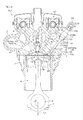
- FIG. 1 is a sectional view of an engine according to a first preferred embodiment of the present invention.
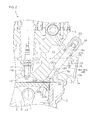
- FIG. 2 is an enlarged view of a portion of FIG. 1 .
- FIG. 3 is a view showing a positional relationship between an intake port and a fuel injector according to the first preferred embodiment of the present invention.
- FIG. 4 is a view showing a positional relationship between the intake port and the fuel injector according to the first preferred embodiment of the present invention.
- FIG. 5 is a view showing a positional relationship between the intake port and the fuel injector according to the first preferred embodiment of the present invention.
- FIG. 6 is a sectional view of an engine according to a second preferred embodiment of the present invention.
- FIG. 7 is a sectional view of an engine according to a third preferred embodiment of the present invention.
- FIG. 8 is a view showing a positional relationship between an intake port and a fuel injector according to a fourth preferred embodiment of the present invention.
- FIG. 9 is a view showing a positional relationship between the intake port and the fuel injector according to the fourth preferred embodiment of the present invention.
- FIG. 10 is a view showing a positional relationship between the intake port and the fuel injector according to the fourth preferred embodiment of the present invention.
- FIG. 11 is a view showing a positional relationship between an intake port and a fuel injector according to a fifth preferred embodiment of the present invention.
- FIG. 12 is a view showing a positional relationship between the intake port and the fuel injector according to the fifth preferred embodiment of the present invention.
- FIG. 13 is a view showing a positional relationship between the intake port and the fuel injector according to the fifth preferred embodiment of the present invention.
- FIG. 1 is a sectional view of an engine 1 according to a first preferred embodiment of the present invention.
- FIG. 2 is an enlarged view of a portion of FIG. 1 .
- a direction in which a rotational axis L1 of a crankshaft 6 extends i.e., a direction perpendicular to the plane of the sheet of paper of the drawing
- a direction in which a central axis L2 of a cylinder perpendicular to the rotational axis L1 extends i.e., an up-down direction in the plane of the sheet of paper of the drawing
- this direction definition is one example, and the direction in which the rotational axis L1 extends may be a direction other than the front-rear direction.
- the engine 1 is a four-stroke engine (internal combustion engine).
- the engine 1 may be mounted in a vehicle, such as an automobile or a motorcycle, or may be mounted in a vessel, or may be mounted in other devices.
- the engine 1 may be mounted in a vessel propulsion apparatus that propels a vessel.
- the engine 1 may be a single cylinder engine or a multi-cylinder engine. If the engine 1 is a multi-cylinder engine, the engine 1 may be a straight-type engine that includes a plurality of cylinders arranged linearly, or may be a V-type engine that includes a plurality of cylinders arranged along the line of the capital letter V, or may be another type of engine.
- the engine 1 includes a cylinder body 2 and a cylinder head 3.
- the cylinder head 3 is disposed above the cylinder body 2.
- the cylinder head 3 is connected to an upper end of the cylinder body 2.
- the cylinder body 2 and the cylinder head 3 define a cylinder 4.
- the engine 1 includes a piston 5 disposed in the cylinder 4, a crankshaft 6 rotatable around the rotational axis L1, and a connecting rod 7 by which the piston 5 and the crankshaft 6 are connected together.
- the engine 1 additionally includes an intake valve 8, an exhaust valve 9, and a valve driving mechanism 10 that drives the intake valve 8 and the exhaust valve 9.
- the cylinder head 3 defines a water jacket 11 through which cooling water flows.
- the cylinder head 3 further defines a combustion chamber 12 in which an air-fuel mixture consisting of air and fuel is burnt, an intake port 13 that communicates with the combustion chamber 12, and an exhaust port 14 that communicates with the combustion chamber 12.
- the intake port 13 and the exhaust port 14 are opened and closed by the intake valve 8 and the exhaust valve 9, respectively.
- Intake air supplied to the engine 1 is supplied from the intake port 13 to the combustion chamber 12 by opening the intake port 13.
- Exhaust gas generated in the combustion chamber 12 is discharged outwardly from the combustion chamber 12 through the exhaust port 14 by opening the exhaust port 14.
- the intake port 13 and the exhaust port 14 pass through the outside of the cylinder head 3 and the combustion chamber 12.
- the intake port 13 extends from the side of the cylinder head 3 to the combustion chamber 12.
- the intake port 13 is preferably shaped like, for example, the capital letter Y that branches off inside the cylinder head 3 (see FIG. 4 ).
- the intake port 13 includes a combined passage 15 that extends from the outside of the cylinder head 3 to the inside of the cylinder head 3 and two branch passages 16 each of which extends from an end of the combined passage 15 to the combustion chamber 12.
- the combined passage 15 is opened at an outer surface of the cylinder head 3, and each branch passage 16 is opened at the combustion chamber 12.
- FIG. 1 the intake port 13 includes a combined passage 15 that extends from the outside of the cylinder head 3 to the inside of the cylinder head 3 and two branch passages 16 each of which extends from an end of the combined passage 15 to the combustion chamber 12.
- the combined passage 15 is opened at an outer surface of the cylinder head 3, and each branch passage 16 is
- the intake port 13 includes an opening 13a located at the outer surface of the cylinder head 3 and an opening 13b located at the combustion chamber 12.
- the intake valve 8 is preferably provided for each branch passage 16, and the opening 13b (intake port) of the branch passage 16 located at the combustion chamber 12 is opened and closed by the corresponding intake valve 8.
- the exhaust port 14 also communicates with the combustion chamber 12 at two places (not shown), and two exhaust valves 9 are provided for two corresponding openings (exhaust ports), respectively, of the exhaust port 14. In other words, in the first preferred embodiment, two intake valves 8 and two exhaust valves 9 that correspond to the same cylinder 4 are provided.
- the engine 1 includes a spark plug 17 that provides sparks in the combustion chamber 12 and a fuel injector 18 that sprays fuel (e.g., gasoline) into the combustion chamber 12.
- the cylinder head 3 defines a plug housing hole 19 in which the spark plug 17 is inserted and a housing hole 20 and a connection hole 21 in both of which the fuel injector 18 is inserted.
- the plug housing hole 19 extends along the central axis L2 of the cylinder 4. Therefore, the spark plug 17 extends along the central axis L2 of the cylinder 4.
- the front end of the spark plug 17 that emits sparks protrudes from the plug housing hole 19, and reaches the combustion chamber 12.
- the housing hole 20 and the connection hole 21 extend in a direction that inclines with respect to the central axis L2 of the cylinder 4.
- the fuel injector 18 inclines with respect to the central axis L2 of the cylinder 4.
- the fuel injector 18 inclines with respect to the central axis L2 of the cylinder 4 at an angle greater than the intake valve 8.
- the fuel injector 18 is disposed outside the spark plug 17 (i.e., in a direction away from the central axis L2 of the cylinder 4).
- the housing hole 20 passes through the combustion chamber 12 and the intake port 13, whereas the connection hole 21 passes through the intake port 13 and the outside of the cylinder head 3. Therefore, the housing hole 20 is disposed between the intake port 13 and the combustion chamber 12, whereas the connection hole 21 is disposed on the side opposite to the housing hole 20 with respect to the intake port 13.
- the housing hole 20 includes an opening 20a located at an inner wall 13c of the intake port 13 and an opening 20b located at the combustion chamber 12.
- the connection hole 21 includes an opening 21a located at an outer surface of the cylinder head 3 and an opening 21b located at an inner wall 13c of the intake port 13.
- the housing hole 20 and the connection hole 21 face each other with the intake port 13 therebetween.
- the housing hole 20 and the connection hole 21 are disposed on the same axis that inclines with respect to the central axis L2 of the cylinder 4.
- the housing hole 20 and the connection hole 21 are opened at the inner wall 13c of the intake port 13.
- the fuel injector 18 is inserted in the opening 20a that faces the intake port 13 of the housing hole 20 and in the opening 21b that faces the intake port 13 of the connection hole 21. Therefore, the fuel injector 18 penetrates through the inner wall 13c of the intake port 13, and intersects the intake port 13.
- the fuel injector 18 intersects the intake port 13 outside an inner circumferential surface of the cylinder 4.
- the fuel injector 18 preferably is cylindrical, for example.
- the fuel injector 18 includes a cylindrical forward end portion 18a that extends in an axial direction (i.e., direction along the central axis of the fuel injector 18) and a body portion 18b.
- the outer diameter of the forward end portion 18a is smaller than that of the body portion 18b.
- the forward end portion 18a extends from the body portion 18b toward the combustion chamber 12.
- the forward end portion 18a is shorter than, for example, the body portion 18b.
- An injection opening through which a mist of fuel is injected is located at the tip of the forward end portion 18a, i.e., is located at the front end of the fuel injector 18.
- the fuel injector 18 is held by the cylinder head 3.
- the fuel injector 18 is inserted from the outside of the cylinder head 3 into the housing hole 20 and the connection hole 21.
- the forward end portion 18a of the fuel injector 18 enters the housing hole 20, whereas the body portion 18b of the fuel injector 18 enters the connection hole 21.
- the forward end portion 18a and the body portion 18b of the fuel injector 18 further enter the intake port 13.
- the forward end portion 18a and the body portion 18b are disposed in the intake port 13 in a posture of intersecting the flow of intake air in the intake port 13.
- the front end of the fuel injector 18 is disposed in the housing hole 20.
- the front end of the fuel injector 18 and the inner wall of the housing hole 20 define a concave portion 22 that communicates with the combustion chamber 12.
- the concave portion 22 is hollowed in a direction away from the combustion chamber 12. As shown in FIG. 2 , a portion of the concave portion 22 that is contiguous to the front end of the fuel injector 18 defines an inlet 22a of the concave portion 22, whereas a portion of the concave portion 22 that is contiguous to the combustion chamber 12 (which corresponds to the opening 20b that faces the combustion chamber 12 of the housing hole 20) defines an outlet 22b of the concave portion 22.
- the area of the outlet 22b of the concave portion 22 is greater than that of the inlet 22a of the concave portion 22.
- the flow passage area of the concave portion 22 may continuously become greater or may stepwise become greater in proportion to an approach to the outlet 22b of the concave portion 22.
- An outer end portion 18c of the fuel injector 18 protrudes from the outer surface of the cylinder head 3.
- the outer end portion 18c of the fuel injector 18 is disposed on the side opposite to the cylinder body 2 with respect to the intake port 13. Therefore, the intake port 13 is disposed between the cylinder body 2 and the outer end portion 18c of the fuel injector 18.
- An end of a fuel supply pipe 23 that supplies fuel to the fuel injector 18 is connected to the outer end portion 18c of the fuel injector 18.
- the fuel injector 18 conically jets fuel, which has been supplied from the fuel supply pipe 23, from its front end toward the combustion chamber 12. A fuel mist jetted from the fuel injector 18 passes through the inlet 22a and then through the outlet 22b of the concave portion 22, and is supplied directly to the combustion chamber 12.
- the area of the outlet 22b of the concave portion 22 is greater than that of the inlet 22a of the concave portion 22, and therefore the fuel mist that spreads from the front end of the fuel injector 18 toward the combustion chamber 12 can be prevented from colliding with the inner wall of the housing hole 20 inside the concave portion 22 so that the spread of the fuel is narrowed.
- the housing hole 20 communicates with the combustion chamber 12 at a more distant position than the intake port 13 with respect to the central axis L2 of the cylinder 4.
- the opening 20b of the housing hole 20 that faces the combustion chamber 12 is disposed outside the opening 13b of the intake port 13 (i.e., opening of the branch passage 16) that faces the combustion chamber 12, and is more distant from the central axis L2 of the cylinder 4 than the opening 13b of the intake port 13. Therefore, the opening 20b of the housing hole 20 that faces the combustion chamber 12 is closer to the inner circumferential surface of the cylinder 4 than the opening 13b of the intake port 13 that faces the combustion chamber 12.
- the opening 13b of the intake port 13 and the opening 20b of the housing hole 20 are disposed on the same side with respect to a plane that includes the central axis L2 of the cylinder 4 and the rotational axis L1 of the crankshaft 6. Therefore, the opening 13b of the intake port 13 and the front end of the fuel injector 18 are disposed on the same side with respect to the plane that includes the central axis L2 of the cylinder 4 and the rotational axis L1 of the crankshaft 6.
- the engine 1 includes a first sealing member 24 and a second sealing member 25.
- the first and second sealing members 24 and 25 preferably are 0 rings made of, for example, heat resisting material. Fluorine resin, such as polytetrafluoroethylene, can be mentioned as the heat resisting material.
- the first sealing member 24 is attached to an annular groove provided at the forward end portion 18a of the fuel injector 18, and concentrically surrounds the forward end portion 18a. A gap between the forward end portion 18a and the inner wall of the housing hole 20 is sealed with the first sealing member 24. As a result, a fluid can be prevented from leaking from the combustion chamber 12 to the intake port 13.
- the second sealing member 25 concentrically surrounds the body portion 18b of the fuel injector 18, and a gap between the body portion 18b and the inner wall of the connection hole 21 is sealed with the second sealing member 25.
- intake air can be prevented from leaking from the intake port 13 to the outside of the cylinder head 3, or air can be prevented from flowing from the outside of the cylinder head 3 into the intake port 13.
- the second sealing member 25 may be disposed at the outside of the cylinder head 3 as shown in FIG. 1 , or may be disposed in the connection hole 21 (see FIG. 6 ).
- FIG. 3 to FIG. 5 are views showing a positional relationship between the intake port 13 and the fuel injector 18 according to the first preferred embodiment of the present invention.
- the intake port 13 includes the two branch passages 16 that communicate with the combustion chamber 12 and the combined passage 15 in which the two branch passages 16 are combined together.
- the two branch pas sages 16 branch of f at an end of the combined passage 15.
- the two branch passages 16 are arranged in the shape of the capital letter V with a space therebetween in a width direction D1.
- the space between the two branch passages 16 is smaller than the width of the fuel injector 18 (i.e., length in the width direction D1).
- the opening 13a of the combined passage 15 located at the outer surface of the cylinder head 3 preferably is, for example, an elongated ellipse that is elongated in the width direction D1.
- the opening 13b of the branch passage 16 located at the combustion chamber 12 preferably is, for example, a circle.
- the opening 13a of the combined passage 15 is an inlet for intake air, whereas the opening 13b of each branch passage 16 is an outlet for intake air.
- the area of the opening 13a of the combined passage 15 is greater than that of the opening 13b of the branch passage 16.
- the flow passage area of the combined passage 15 is greater than that of the branch passage 16.
- the fuel injector 18 penetrates through the inner wall of the combined passage 15 at an intermediate portion of the combined passage 15 with respect to the width direction D1.
- the fuel injector 18 is disposed at a position at which the intake port 13 is halved in the width direction D1. Additionally, when the intake port 13 and the fuel injector 18 are viewed from the inlet side of intake air, the fuel injector 18 overlaps with the two branch passages 16. Intake air that has flowed into the intake port 13 from the opening 13a of the combined passage 15 is branched off into two intake air parts at the joint between the combined passage 15 and the two branch passages 16, and is supplied from the opening 13b of each branch passage 16 to the combustion chamber 12.
- the fuel injector 18 When the intake port 13 and the fuel injector 18 are viewed from the inlet side of intake air, the fuel injector 18 is not unevenly placed at one of the branch passages 16, and therefore the intake air that has flowed into the combined passage 15 is branched off into two intake air portions such that these two portions become substantially equal to each other in the amount of flow, and flows into each branch passage 16.
- the housing hole 20 passing through the combustion chamber 12 and through the intake port 13 is preferably located in the cylinder head 3.
- the connection hole 21 by which the intake port 13 and the outside of the cylinder head 3 are connected together is located in the cylinder head 3.
- a portion of the fuel injector 18 is disposed at the intake port 13, the housing hole 20, and the connection hole 21.
- the fuel injector 18 jets a fuel mist toward the combustion chamber 12.
- the fuel mist jetted from the fuel injector 18 is supplied directly to the combustion chamber 12. Therefore, it is possible to evaporate the fuel in the cylinder 4 and cool the inside of the cylinder 4. Therefore, the output and the fuel efficiency of the four-stroke engine 1 can be improved.
- an intake system has a high degree of freedom, and therefore the fluid resistance in the intake port 13 can be decreased. Therefore, a decrease in the amount of air that flows from the intake port 13 to the cylinder 4 can be reduced.
- the intake system has a high degree of freedom, and therefore, for example, the shape of the intake port 13 can be made the same as an arrangement configured to jet fuel to the intake port (so-called port injection).
- the intake port 13 preferably includes the two branch passages 16 and the combined passages 15, and the fuel injector 18 penetrates through the inner wall of the combined passage 15.
- the flow passage area of a portion (penetration portion) of the fuel injector 18 penetrating through the intake port 13 decreases. Therefore, the fluid resistance in the penetration portion increases.
- the decrease ratio of the flow passage area in the penetration portion is smaller than in a case in which the intake port 13 penetrates through the branch passage 16 because the flow passage area of the combined passage 15 is greater than that of the branch passage 16. Therefore, an influence exerted on intake air flowing toward the combustion chamber 12 canbe made smaller than in a case in which the intake port 13 penetrates through the branch passage 16.
- the front end of the fuel injector 18 is disposed at the housing hole 20.
- the front end of the fuel injector 18 is exposed to high-temperature exhaust gas. Therefore, in this case, the temperature of the front end of the fuel injector 18 rises. Therefore, a rise in temperature of the front end of the fuel injector 18 can be reduced by disposing the front end of the fuel injector 18 at the housing hole 20. As a result, the front end of the fuel injector 18 can be prevented frombeing blocked with soot that is a carbon deposit.
- soot is easily generated in a high-fuel-concentration and high-temperature atmosphere.
- An injection opening through which fuel is jetted is provided at the front end of the fuel injector 18, and therefore the fuel concentration is high near the front end of the fuel injector 18. Therefore, when the temperature is high near the front end of the fuel injector 18, soot is easily generated.
- the fuel injector 18 is prevented from becoming high in temperature, and therefore the temperature is low near the front end of the fuel injector 18. Therefore, soot can be prevented from being generated. As a result, the front end of the fuel injector 18 can be prevented from being blocked therewith.
- the front end of the fuel injector 18 is disposed at the housing hole 20, and the water jacket 11 to which cooling water is supplied is located at the cylinder head 3.
- the cylinder head 3 is cooled with cooling water supplied to the water jacket 11, and the fuel injector 18 is cooled with the cylinder head 3. Therefore, in a case in which the front end of the fuel injector 18 is disposed the combustion chamber 12, the front end of the fuel injector 18 is spaced away from the cylinder head 3, and therefore the temperature of the front end of the fuel injector 18 becomes higher than in a case in which the front end of the fuel injector 18 is disposed at the housing hole 20. Therefore, a rise in temperature of the front end of the fuel injector 18 can be reduced, and the front end of the fuel injector 18 can be prevented from being blocked with soot by disposing the front end of the fuel injector 18 at the housing hole 20.
- an engine 201 according to a second preferred embodiment shown in FIG. 6 may be arranged in which a fuel injector 218 includes a forward end portion 218a that is longer than a body portion 218b and in which only the forward end portion 218a enters the combined passage 15.
- the front end of the fuel injector 18 is preferably disposed at the housing hole 20.
- the fuel injector 18 may be disposed so that a forward end surface of the fuel injector 18 and an inner wall surface of the combustion chamber 12 are contiguous to each other. In other words, a portion around the housing hole 20 in the inner wall surface of the combustion chamber 12 and the forward end surface of the fuel injector 18 may be disposed on the same plane.
- a housing hole 320 is located so that the front end of the fuel injector 18 reaches the combustion chamber 12 and in which the fuel injector 18 protrudes from the housing hole 320. According to this arrangement, the front end of the fuel injector 18 protrudes from the housing hole 320, and therefore a fuel mist jetted from the fuel injector 18 can be prevented from colliding with the inner wall of the housing hole 320 so that the spread of the fuel is narrowed.
- a portion of the fuel injector 18 may enter intake ports 413 and 513.
- an arrangement may be provided in which the periphery of the fuel injector 18 is partially surrounded by the intake ports 413 and 513 and in which a portion that enters the intake ports 413 and 513 and a portion that is exposed from the intake ports 413 and 513 are included in the cross section of the fuel injector 18 perpendicular to the axial direction.
- an intake port 413 may be arranged so that a portion of the fuel injector 18 is disposed between two branch passages 416.
- the body portion 18b enters the combined passage 415, and enters each branch passage 416.
- the forward end portion 18a may enter the combined passage 415 and each branch passage 416 (not shown).
- an intake port 513 may be arranged such that the fuel injector 18 is disposed between two branch passages 516 and such that a portion of the body portion 18b enters each branch passage 516. Additionally, in the fifth preferred embodiment, the forward end portion 18a may enter each branch passage 516 (not shown) Additionally, in the fifth preferred embodiment, the two branch passages 516 may be joined to a combined passage shared by these passages 516, or may be independent of each other. In other words, two intake ports that are independent of each other may be provided, and the fuel injector 18 may be disposed between these intake ports.
- the intake port 13 includes the two branch passages 16.
- the intake port 13 may include three or more branch passages 16, for example. Additionally, the intake port 13 may not be branched off. In this case, the number of the intake ports 13 corresponding to the same cylinder 4 may be one, or may be two or more.
- Combustion chamber Combustion chamber 12
- Intake port Intake port 13, 413, 513 Housing hole: Housing hole 20,
- Cylinder head Cylinder head 3
- Fuel injector Fuel injector 18, 218 Four-stroke engine: Engine 1, 201, 301
- Inner wall of intake port Inner wall 13c of intake port
- Branch passage Branch passage 16, 416, 516
- Combined passage Combined passage 15, 415
- First sealing member First sealing member 24
- Cylinder Cylinder 4
- Cylinder body Cylinder body 2
- Second sealing member Second sealing member 25
- Body portion Body portion 18b Forward end portion: Forward end portion 18a, 218a
Landscapes
- Engineering & Computer Science (AREA)
- Chemical & Material Sciences (AREA)
- Combustion & Propulsion (AREA)
- Mechanical Engineering (AREA)
- General Engineering & Computer Science (AREA)
- Cylinder Crankcases Of Internal Combustion Engines (AREA)
- Fuel-Injection Apparatus (AREA)
Abstract
Description
- The present invention relates to a four-stroke engine.
- A direct-injection engine is known in which liquid fuel is supplied directly to a combustion chamber so as to improve its output and fuel efficiency.
- In the direct-injection engine, fuel is evaporated in a cylinder, and, as a result, the inside of the cylinder is cooled. Therefore, the output of the engine can be improved by increasing the amount of air with which the cylinder is filled. In addition, the temperature of the inside of the cylinder decreases, and therefore knocking can be prevented. Therefore, fuel efficiency can be improved by increasing the compression ratio of an air-fuel mixture.
- United States Patent No.
6, 053, 145 discloses an engine in which liquid fuel is supplied directly to a combustion chamber. In the engine of United States Patent No.6, 053, 145 , a fuel injector that jets fuel is disposed near intake ports. Two intake ports are provided for each cylinder. The fuel injector is disposed between the two intake ports or is disposed therebelow (i.e., is disposed on a cylinder-body side). - The inventors of preferred embodiments of the present invention described and claimed in the present application conducted an extensive study and research regarding a four-stroke engine, such as the one described above, and in doing so, discovered and first recognized new unique challenges and previously unrecognized possibilities for improvements as described in greater detail below.
- As described above, in the engine of United States Patent No.
6,053,145 , the fuel injector is disposed between the two intake ports or is disposed therebelow. However, in a case in which the fuel injector is disposed between the two intake ports, a space in which the fuel injector is disposed is ensured by greatly curving each intake port or by adjusting the distance between the two intake ports. Therefore, the shape or layout of the intake ports is restricted because of the fuel injector. Likewise, in a case in which the fuel injector is disposed below the intake ports, the shape or layout of the intake ports is restricted because of the fuel injector. However, if the intake port is greatly curved, fluid resistance at the intake port will increase, and the flow of intake air toward the combustion chamber will be obstructed. Therefore, the flow rate of air filled from the intake port into the cylinder will decrease, and the effect brought about by direct injection will decrease. - In order to over come the previously unrecognized and unsolved challenges described above, one preferred embodiment of the present invention provides a four-stroke engine that includes a cylinder head in which a combustion chamber, an intake port that communicates with the combustion chamber, and a housing hole that passes through the combustion chamber and through the intake port are defined; and a fuel injector at least a portion of which is disposed at the intake port and at the housing hole and that supplies a mist of fuel directly to the combustion chamber by jetting the mist of fuel toward the combustion chamber.
- According to this arrangement, the housing hole that passes through the combustion chamber and through the intake port is located in the cylinder head, and at least a portion of the fuel injector is disposed at the intake port and at the housing hole. The fuel injector jets a fuel mist toward the combustion chamber. The fuel mist (i.e., liquid droplets of fuel) jetted from the fuel injector is supplied directly to the combustion chamber. Therefore, the inside of the cylinder can be cooled by evaporating the fuel in the cylinder. Therefore, the output and the fuel efficiency of the four-stroke engine are significantly improved. Additionally, at least a portion of the fuel injector is disposed at the intake port, and therefore the shape or layout of the intake port is not required to be changed in order to provide a space to dispose the fuel injector. Thus, an intake system has a high degree of freedom, and therefore the fluid resistance in the intake port can be decreased. Therefore, a decrease in the amount of air that flows from the intake port to the cylinder can be reduced.
- A front end of the fuel injector may reach the combustion chamber.
- The fuel injector may penetrate through an inner wall of the intake port.
- The intake port may include a plurality of branch passages that communicate with the combustion chamber and a combined passage in which the plurality of branch passages are combined together. In this case, the fuel injector may penetrate through an inner wall of the combined passage, or may enter at least one of the plurality of branch passages.
- The four-stroke engine may further include a first sealing member with which a gap between the fuel injector and the housing hole is sealed.
- The four-stroke engine may further include a cylinder body including a cylinder. In this case, the housing hole may communicate with the combustion chamber at a more distant position than the intake port with respect to a central axis of the cylinder.
- The cylinder head may include a connection hole by which the intake port and an outside of the cylinder head are connected together. In this case, the fuel injector may enter the connection hole.
- The four-stroke engine may further include a second sealing member with which a gap between the fuel injector and the connection hole is sealed.
- The fuel injector may include a body portion entering the intake port.
- The fuel injector may include a forward end portion entering the intake port.
- The four-stroke engine may further include a cylinder body including a cylinder. In this case, the fuel injector may be inclined with respect to the central axis of the cylinder.
- The above and other elements, features, steps, characteristics and advantages of the present invention will become more apparent from the following detailed description of the preferred embodiments with reference to the attached drawings.
-
FIG. 1 is a sectional view of an engine according to a first preferred embodiment of the present invention. -
FIG. 2 is an enlarged view of a portion ofFIG. 1 . -
FIG. 3 is a view showing a positional relationship between an intake port and a fuel injector according to the first preferred embodiment of the present invention. -
FIG. 4 is a view showing a positional relationship between the intake port and the fuel injector according to the first preferred embodiment of the present invention. -
FIG. 5 is a view showing a positional relationship between the intake port and the fuel injector according to the first preferred embodiment of the present invention. -
FIG. 6 is a sectional view of an engine according to a second preferred embodiment of the present invention. -
FIG. 7 is a sectional view of an engine according to a third preferred embodiment of the present invention. -
FIG. 8 is a view showing a positional relationship between an intake port and a fuel injector according to a fourth preferred embodiment of the present invention. -
FIG. 9 is a view showing a positional relationship between the intake port and the fuel injector according to the fourth preferred embodiment of the present invention. -
FIG. 10 is a view showing a positional relationship between the intake port and the fuel injector according to the fourth preferred embodiment of the present invention. -
FIG. 11 is a view showing a positional relationship between an intake port and a fuel injector according to a fifth preferred embodiment of the present invention. -
FIG. 12 is a view showing a positional relationship between the intake port and the fuel injector according to the fifth preferred embodiment of the present invention. -
FIG. 13 is a view showing a positional relationship between the intake port and the fuel injector according to the fifth preferred embodiment of the present invention. -
FIG. 1 is a sectional view of an engine 1 according to a first preferred embodiment of the present invention.FIG. 2 is an enlarged view of a portion ofFIG. 1 . In the following description, a direction in which a rotational axis L1 of acrankshaft 6 extends (i.e., a direction perpendicular to the plane of the sheet of paper of the drawing) is defined as a front-rear direction, and a direction in which a central axis L2 of a cylinder perpendicular to the rotational axis L1 extends (i.e., an up-down direction in the plane of the sheet of paper of the drawing) is defined as an up-down direction. However, this direction definition is one example, and the direction in which the rotational axis L1 extends may be a direction other than the front-rear direction. - The engine 1 is a four-stroke engine (internal combustion engine). The engine 1 may be mounted in a vehicle, such as an automobile or a motorcycle, or may be mounted in a vessel, or may be mounted in other devices. For example, the engine 1 may be mounted in a vessel propulsion apparatus that propels a vessel. Additionally, the engine 1 may be a single cylinder engine or a multi-cylinder engine. If the engine 1 is a multi-cylinder engine, the engine 1 may be a straight-type engine that includes a plurality of cylinders arranged linearly, or may be a V-type engine that includes a plurality of cylinders arranged along the line of the capital letter V, or may be another type of engine.
- The engine 1 includes a
cylinder body 2 and acylinder head 3. Thecylinder head 3 is disposed above thecylinder body 2. Thecylinder head 3 is connected to an upper end of thecylinder body 2. Thecylinder body 2 and thecylinder head 3 define acylinder 4. The engine 1 includes apiston 5 disposed in thecylinder 4, acrankshaft 6 rotatable around the rotational axis L1, and a connectingrod 7 by which thepiston 5 and thecrankshaft 6 are connected together. The engine 1 additionally includes anintake valve 8, anexhaust valve 9, and avalve driving mechanism 10 that drives theintake valve 8 and theexhaust valve 9. - The
cylinder head 3 defines awater jacket 11 through which cooling water flows. Thecylinder head 3 further defines acombustion chamber 12 in which an air-fuel mixture consisting of air and fuel is burnt, anintake port 13 that communicates with thecombustion chamber 12, and anexhaust port 14 that communicates with thecombustion chamber 12. Theintake port 13 and theexhaust port 14 are opened and closed by theintake valve 8 and theexhaust valve 9, respectively. Intake air supplied to the engine 1 is supplied from theintake port 13 to thecombustion chamber 12 by opening theintake port 13. Exhaust gas generated in thecombustion chamber 12 is discharged outwardly from thecombustion chamber 12 through theexhaust port 14 by opening theexhaust port 14. - The
intake port 13 and theexhaust port 14 pass through the outside of thecylinder head 3 and thecombustion chamber 12. Theintake port 13 extends from the side of thecylinder head 3 to thecombustion chamber 12. Theintake port 13 is preferably shaped like, for example, the capital letter Y that branches off inside the cylinder head 3 (seeFIG. 4 ). As shown inFIG. 1 , theintake port 13 includes a combinedpassage 15 that extends from the outside of thecylinder head 3 to the inside of thecylinder head 3 and twobranch passages 16 each of which extends from an end of the combinedpassage 15 to thecombustion chamber 12. The combinedpassage 15 is opened at an outer surface of thecylinder head 3, and eachbranch passage 16 is opened at thecombustion chamber 12. As shown inFIG. 1 , theintake port 13 includes anopening 13a located at the outer surface of thecylinder head 3 and anopening 13b located at thecombustion chamber 12. Theintake valve 8 is preferably provided for eachbranch passage 16, and theopening 13b (intake port) of thebranch passage 16 located at thecombustion chamber 12 is opened and closed by the correspondingintake valve 8. Theexhaust port 14 also communicates with thecombustion chamber 12 at two places (not shown), and twoexhaust valves 9 are provided for two corresponding openings (exhaust ports), respectively, of theexhaust port 14. In other words, in the first preferred embodiment, twointake valves 8 and twoexhaust valves 9 that correspond to thesame cylinder 4 are provided. - The engine 1 includes a
spark plug 17 that provides sparks in thecombustion chamber 12 and afuel injector 18 that sprays fuel (e.g., gasoline) into thecombustion chamber 12. Thecylinder head 3 defines aplug housing hole 19 in which thespark plug 17 is inserted and ahousing hole 20 and aconnection hole 21 in both of which thefuel injector 18 is inserted. Theplug housing hole 19 extends along the central axis L2 of thecylinder 4. Therefore, thespark plug 17 extends along the central axis L2 of thecylinder 4. The front end of thespark plug 17 that emits sparks protrudes from theplug housing hole 19, and reaches thecombustion chamber 12. Thehousing hole 20 and theconnection hole 21 extend in a direction that inclines with respect to the central axis L2 of thecylinder 4. Therefore, thefuel injector 18 inclines with respect to the central axis L2 of thecylinder 4. Thefuel injector 18 inclines with respect to the central axis L2 of thecylinder 4 at an angle greater than theintake valve 8. Thefuel injector 18 is disposed outside the spark plug 17 (i.e., in a direction away from the central axis L2 of the cylinder 4). - The
housing hole 20 passes through thecombustion chamber 12 and theintake port 13, whereas theconnection hole 21 passes through theintake port 13 and the outside of thecylinder head 3. Therefore, thehousing hole 20 is disposed between theintake port 13 and thecombustion chamber 12, whereas theconnection hole 21 is disposed on the side opposite to thehousing hole 20 with respect to theintake port 13. As shown inFIG. 2 , thehousing hole 20 includes anopening 20a located at aninner wall 13c of theintake port 13 and anopening 20b located at thecombustion chamber 12. Theconnection hole 21 includes anopening 21a located at an outer surface of thecylinder head 3 and anopening 21b located at aninner wall 13c of theintake port 13. Thehousing hole 20 and theconnection hole 21 face each other with theintake port 13 therebetween. Thehousing hole 20 and theconnection hole 21 are disposed on the same axis that inclines with respect to the central axis L2 of thecylinder 4. Thehousing hole 20 and theconnection hole 21 are opened at theinner wall 13c of theintake port 13. Thefuel injector 18 is inserted in theopening 20a that faces theintake port 13 of thehousing hole 20 and in theopening 21b that faces theintake port 13 of theconnection hole 21. Therefore, thefuel injector 18 penetrates through theinner wall 13c of theintake port 13, and intersects theintake port 13. Thefuel injector 18 intersects theintake port 13 outside an inner circumferential surface of thecylinder 4. - The
fuel injector 18 preferably is cylindrical, for example. Thefuel injector 18 includes a cylindricalforward end portion 18a that extends in an axial direction (i.e., direction along the central axis of the fuel injector 18) and abody portion 18b. The outer diameter of theforward end portion 18a is smaller than that of thebody portion 18b. Theforward end portion 18a extends from thebody portion 18b toward thecombustion chamber 12. Theforward end portion 18a is shorter than, for example, thebody portion 18b. An injection opening through which a mist of fuel is injected is located at the tip of theforward end portion 18a, i.e., is located at the front end of thefuel injector 18. Thefuel injector 18 is held by thecylinder head 3. Thefuel injector 18 is inserted from the outside of thecylinder head 3 into thehousing hole 20 and theconnection hole 21. Theforward end portion 18a of thefuel injector 18 enters thehousing hole 20, whereas thebody portion 18b of thefuel injector 18 enters theconnection hole 21. Theforward end portion 18a and thebody portion 18b of thefuel injector 18 further enter theintake port 13. Theforward end portion 18a and thebody portion 18b are disposed in theintake port 13 in a posture of intersecting the flow of intake air in theintake port 13. - The front end of the
fuel injector 18 is disposed in thehousing hole 20. The front end of thefuel injector 18 and the inner wall of thehousing hole 20 define aconcave portion 22 that communicates with thecombustion chamber 12. Theconcave portion 22 is hollowed in a direction away from thecombustion chamber 12. As shown inFIG. 2 , a portion of theconcave portion 22 that is contiguous to the front end of thefuel injector 18 defines aninlet 22a of theconcave portion 22, whereas a portion of theconcave portion 22 that is contiguous to the combustion chamber 12 (which corresponds to theopening 20b that faces thecombustion chamber 12 of the housing hole 20) defines anoutlet 22b of theconcave portion 22. The area of theoutlet 22b of theconcave portion 22 is greater than that of theinlet 22a of theconcave portion 22. The flow passage area of theconcave portion 22 may continuously become greater or may stepwise become greater in proportion to an approach to theoutlet 22b of theconcave portion 22. - An
outer end portion 18c of thefuel injector 18 protrudes from the outer surface of thecylinder head 3. Theouter end portion 18c of thefuel injector 18 is disposed on the side opposite to thecylinder body 2 with respect to theintake port 13. Therefore, theintake port 13 is disposed between thecylinder body 2 and theouter end portion 18c of thefuel injector 18. An end of afuel supply pipe 23 that supplies fuel to thefuel injector 18 is connected to theouter end portion 18c of thefuel injector 18. Thefuel injector 18 conically jets fuel, which has been supplied from thefuel supply pipe 23, from its front end toward thecombustion chamber 12. A fuel mist jetted from thefuel injector 18 passes through theinlet 22a and then through theoutlet 22b of theconcave portion 22, and is supplied directly to thecombustion chamber 12. The area of theoutlet 22b of theconcave portion 22 is greater than that of theinlet 22a of theconcave portion 22, and therefore the fuel mist that spreads from the front end of thefuel injector 18 toward thecombustion chamber 12 can be prevented from colliding with the inner wall of thehousing hole 20 inside theconcave portion 22 so that the spread of the fuel is narrowed. - As shown in
FIG. 1 , thehousing hole 20 communicates with thecombustion chamber 12 at a more distant position than theintake port 13 with respect to the central axis L2 of thecylinder 4. Theopening 20b of thehousing hole 20 that faces thecombustion chamber 12 is disposed outside theopening 13b of the intake port 13 (i.e., opening of the branch passage 16) that faces thecombustion chamber 12, and is more distant from the central axis L2 of thecylinder 4 than theopening 13b of theintake port 13. Therefore, theopening 20b of thehousing hole 20 that faces thecombustion chamber 12 is closer to the inner circumferential surface of thecylinder 4 than theopening 13b of theintake port 13 that faces thecombustion chamber 12. Theopening 13b of theintake port 13 and theopening 20b of thehousing hole 20 are disposed on the same side with respect to a plane that includes the central axis L2 of thecylinder 4 and the rotational axis L1 of thecrankshaft 6. Therefore, theopening 13b of theintake port 13 and the front end of thefuel injector 18 are disposed on the same side with respect to the plane that includes the central axis L2 of thecylinder 4 and the rotational axis L1 of thecrankshaft 6. - The engine 1 includes a first sealing
member 24 and asecond sealing member 25. The first andsecond sealing members first sealing member 24 is attached to an annular groove provided at theforward end portion 18a of thefuel injector 18, and concentrically surrounds theforward end portion 18a. A gap between theforward end portion 18a and the inner wall of thehousing hole 20 is sealed with the first sealingmember 24. As a result, a fluid can be prevented from leaking from thecombustion chamber 12 to theintake port 13. Likewise, the second sealingmember 25 concentrically surrounds thebody portion 18b of thefuel injector 18, and a gap between thebody portion 18b and the inner wall of theconnection hole 21 is sealed with the second sealingmember 25. As a result, intake air can be prevented from leaking from theintake port 13 to the outside of thecylinder head 3, or air can be prevented from flowing from the outside of thecylinder head 3 into theintake port 13. Thesecond sealing member 25 may be disposed at the outside of thecylinder head 3 as shown inFIG. 1 , or may be disposed in the connection hole 21 (seeFIG. 6 ). -
FIG. 3 to FIG. 5 are views showing a positional relationship between theintake port 13 and thefuel injector 18 according to the first preferred embodiment of the present invention. - As described above, the
intake port 13 includes the twobranch passages 16 that communicate with thecombustion chamber 12 and the combinedpassage 15 in which the twobranch passages 16 are combined together. The twobranch pas sages 16 branch of f at an end of the combinedpassage 15. The twobranch passages 16 are arranged in the shape of the capital letter V with a space therebetween in a width direction D1. The space between the twobranch passages 16 is smaller than the width of the fuel injector 18 (i.e., length in the width direction D1). Theopening 13a of the combinedpassage 15 located at the outer surface of thecylinder head 3 preferably is, for example, an elongated ellipse that is elongated in the width direction D1. Theopening 13b of thebranch passage 16 located at thecombustion chamber 12 preferably is, for example, a circle. Theopening 13a of the combinedpassage 15 is an inlet for intake air, whereas theopening 13b of eachbranch passage 16 is an outlet for intake air. The area of theopening 13a of the combinedpassage 15 is greater than that of theopening 13b of thebranch passage 16. The flow passage area of the combinedpassage 15 is greater than that of thebranch passage 16. - The
fuel injector 18 penetrates through the inner wall of the combinedpassage 15 at an intermediate portion of the combinedpassage 15 with respect to the width direction D1. When theintake port 13 and thefuel injector 18 are viewed from the inlet side of intake air, thefuel injector 18 is disposed at a position at which theintake port 13 is halved in the width direction D1. Additionally, when theintake port 13 and thefuel injector 18 are viewed from the inlet side of intake air, thefuel injector 18 overlaps with the twobranch passages 16. Intake air that has flowed into theintake port 13 from theopening 13a of the combinedpassage 15 is branched off into two intake air parts at the joint between the combinedpassage 15 and the twobranch passages 16, and is supplied from theopening 13b of eachbranch passage 16 to thecombustion chamber 12. When theintake port 13 and thefuel injector 18 are viewed from the inlet side of intake air, thefuel injector 18 is not unevenly placed at one of thebranch passages 16, and therefore the intake air that has flowed into the combinedpassage 15 is branched off into two intake air portions such that these two portions become substantially equal to each other in the amount of flow, and flows into eachbranch passage 16. - As described above, in the first preferred embodiment, the
housing hole 20 passing through thecombustion chamber 12 and through theintake port 13 is preferably located in thecylinder head 3. Additionally, theconnection hole 21 by which theintake port 13 and the outside of thecylinder head 3 are connected together is located in thecylinder head 3. A portion of thefuel injector 18 is disposed at theintake port 13, thehousing hole 20, and theconnection hole 21. Thefuel injector 18 jets a fuel mist toward thecombustion chamber 12. The fuel mist jetted from thefuel injector 18 is supplied directly to thecombustion chamber 12. Therefore, it is possible to evaporate the fuel in thecylinder 4 and cool the inside of thecylinder 4. Therefore, the output and the fuel efficiency of the four-stroke engine 1 can be improved. Additionally, a portion of thefuel injector 18 is disposed at theintake port 13, and therefore the shape or layout of theintake port 13 is not required to be changed in order to provide a space for disposing thefuel injector 18. Thus, an intake system has a high degree of freedom, and therefore the fluid resistance in theintake port 13 can be decreased. Therefore, a decrease in the amount of air that flows from theintake port 13 to thecylinder 4 can be reduced. Additionally, the intake system has a high degree of freedom, and therefore, for example, the shape of theintake port 13 can be made the same as an arrangement configured to jet fuel to the intake port (so-called port injection). - Additionally, in the first preferred embodiment, the
intake port 13 preferably includes the twobranch passages 16 and the combinedpassages 15, and thefuel injector 18 penetrates through the inner wall of the combinedpassage 15. In a case in which thefuel injector 18 penetrates through theintake port 13, the flow passage area of a portion (penetration portion) of thefuel injector 18 penetrating through theintake port 13 decreases. Therefore, the fluid resistance in the penetration portion increases. However, in this case, the decrease ratio of the flow passage area in the penetration portion is smaller than in a case in which theintake port 13 penetrates through thebranch passage 16 because the flow passage area of the combinedpassage 15 is greater than that of thebranch passage 16. Therefore, an influence exerted on intake air flowing toward thecombustion chamber 12 canbe made smaller than in a case in which theintake port 13 penetrates through thebranch passage 16. - Additionally, in the first preferred embodiment, the front end of the
fuel injector 18 is disposed at thehousing hole 20. In a case in which the front end of thefuel injector 18 is disposed at thecombustion chamber 12, the front end of thefuel injector 18 is exposed to high-temperature exhaust gas. Therefore, in this case, the temperature of the front end of thefuel injector 18 rises. Therefore, a rise in temperature of the front end of thefuel injector 18 can be reduced by disposing the front end of thefuel injector 18 at thehousing hole 20. As a result, the front end of thefuel injector 18 can be prevented frombeing blocked with soot that is a carbon deposit. - In detail, soot is easily generated in a high-fuel-concentration and high-temperature atmosphere. An injection opening through which fuel is jetted is provided at the front end of the
fuel injector 18, and therefore the fuel concentration is high near the front end of thefuel injector 18. Therefore, when the temperature is high near the front end of thefuel injector 18, soot is easily generated. However, in the first preferred embodiment, thefuel injector 18 is prevented from becoming high in temperature, and therefore the temperature is low near the front end of thefuel injector 18. Therefore, soot can be prevented from being generated. As a result, the front end of thefuel injector 18 can be prevented from being blocked therewith. - Additionally, in the first preferred embodiment, the front end of the
fuel injector 18 is disposed at thehousing hole 20, and thewater jacket 11 to which cooling water is supplied is located at thecylinder head 3. Thecylinder head 3 is cooled with cooling water supplied to thewater jacket 11, and thefuel injector 18 is cooled with thecylinder head 3. Therefore, in a case in which the front end of thefuel injector 18 is disposed thecombustion chamber 12, the front end of thefuel injector 18 is spaced away from thecylinder head 3, and therefore the temperature of the front end of thefuel injector 18 becomes higher than in a case in which the front end of thefuel injector 18 is disposed at thehousing hole 20. Therefore, a rise in temperature of the front end of thefuel injector 18 can be reduced, and the front end of thefuel injector 18 can be prevented from being blocked with soot by disposing the front end of thefuel injector 18 at thehousing hole 20. - Next, other preferred embodiments of the present invention will be described.
- In the first preferred embodiment mentioned above, a description has been given of a case in which the
forward end portion 18a and thebody portion 18b of thefuel injector 18 preferably enter the combinedpassage 15. However, only thebody portion 18b may enter the combinedpassage 15. Additionally, an engine 201 according to a second preferred embodiment shown inFIG. 6 may be arranged in which afuel injector 218 includes aforward end portion 218a that is longer than abody portion 218b and in which only theforward end portion 218a enters the combinedpassage 15. - Additionally, in the first preferred embodiment mentioned above, a description has been given of a case in which the front end of the
fuel injector 18 is preferably disposed at thehousing hole 20. However, thefuel injector 18 may be disposed so that a forward end surface of thefuel injector 18 and an inner wall surface of thecombustion chamber 12 are contiguous to each other. In other words, a portion around thehousing hole 20 in the inner wall surface of thecombustion chamber 12 and the forward end surface of thefuel injector 18 may be disposed on the same plane. Additionally, anengine 301 according to a third preferred embodiment shown inFIG. 7 may be arranged in which ahousing hole 320 is located so that the front end of thefuel injector 18 reaches thecombustion chamber 12 and in which thefuel injector 18 protrudes from thehousing hole 320. According to this arrangement, the front end of thefuel injector 18 protrudes from thehousing hole 320, and therefore a fuel mist jetted from thefuel injector 18 can be prevented from colliding with the inner wall of thehousing hole 320 so that the spread of the fuel is narrowed. - Additionally, in the first preferred embodiment mentioned above, a description has been given of a case in which the
fuel injector 18 preferably penetrates through theintake port 13. In other words, in the first preferred embodiment, a description has been given of a case in which the whole circumference of thefuel injector 18 is preferably surrounded by theintake port 13. However, as shown inFIG. 8 to FIG. 13 , a portion of thefuel injector 18 may enterintake ports fuel injector 18 is partially surrounded by theintake ports intake ports intake ports fuel injector 18 perpendicular to the axial direction. - In detail, as shown in
FIG. 8 to FIG. 10 , anintake port 413 according to a fourth preferred embodiment may be arranged so that a portion of thefuel injector 18 is disposed between twobranch passages 416. In the fourth preferred embodiment, thebody portion 18b enters the combinedpassage 415, and enters eachbranch passage 416. Additionally, in the fourth preferred embodiment, theforward end portion 18a may enter the combinedpassage 415 and each branch passage 416 (not shown). - Additionally, as shown in
FIG. 11 to FIG. 13 , anintake port 513 according to a fifth preferred embodiment may be arranged such that thefuel injector 18 is disposed between twobranch passages 516 and such that a portion of thebody portion 18b enters eachbranch passage 516. Additionally, in the fifth preferred embodiment, theforward end portion 18a may enter each branch passage 516 (not shown) Additionally, in the fifth preferred embodiment, the twobranch passages 516 may be joined to a combined passage shared by thesepassages 516, or may be independent of each other. In other words, two intake ports that are independent of each other may be provided, and thefuel injector 18 may be disposed between these intake ports. - Additionally, in the first preferred embodiment mentioned above, a description has been given of a case in which the
intake port 13 includes the twobranch passages 16. However, theintake port 13 may include three ormore branch passages 16, for example. Additionally, theintake port 13 may not be branched off. In this case, the number of theintake ports 13 corresponding to thesame cylinder 4 may be one, or may be two or more. - In addition, the present invention can be variously modified within the scope of the appended claims.
- Non-limiting examples of correspondence relationships between the constituent elements recited in the appended claims and the constituent elements described in the above preferred embodiments are shown below.
Combustion chamber:Combustion chamber 12
Intake port:Intake port
Housing hole:Housing hole
Cylinder head:Cylinder head 3
Fuel injector:Fuel injector
Four-stroke engine:Engine 1, 201, 301
Inner wall of intake port:Inner wall 13c of intake port
Branch passage:Branch passage
Combined passage:Combined passage
First sealing member:First sealing member 24
Cylinder:Cylinder 4
Cylinder body:Cylinder body 2
Central axis of cylinder: Central axis L2 of cylinder
Connection hole:Connection hole 21
Second sealing member:Second sealing member 25
Body portion:Body portion 18b
Forward end portion:Forward end portion - The present application corresponds to Japanese Patent Application No.
2011-116254 - While preferred embodiments of the present invention have been described above, it is to be understood that variations and modifications will be apparent to those skilled in the art without departing from the scope and spirit of the present invention. The scope of the present invention, therefore, is to be determined solely by the following claims.
Claims (12)
- A four-stroke engine (1, 201, 301) comprising:a cylinder head (3) including a combustion chamber (12), an intake port (13, 413, 513) that communicates with the combustion chamber (12), and a housing hole (20, 320) that passes through the combustion chamber (12) and through the intake port (13, 413, 513); anda fuel injector (18, 218) that supplies a mist of fuel directly to the combustion chamber (12) by jetting the mist of fuel toward the combustion chamber (12), at least a portion of the fuel injector (18, 218) being disposed at the intake port (13, 413, 513) and at the housing hole (20, 320).
- The four-stroke engine (1, 201, 301) according to claim 1, wherein a front end of the fuel injector (18, 218) extends to the combustion chamber (12).
- The four-stroke engine (1, 201, 301) according to claim 1 or claim 2, wherein the fuel injector (18, 218) penetrates through an inner wall (13c) of the intake port (13, 413, 513).
- The four-stroke engine (1, 201, 301) according to claim 3, wherein the intake port (13, 413, 513) includes a plurality of branch passages (16, 416, 516) that communicate with the combustion chamber (12) and a combined passage (15, 415) in which the plurality of branch passages (16, 416, 516) are combined together, and the fuel injector (18, 218) penetrates through an inner wall of the combined passage (15, 415).
- The four-stroke engine (1, 201, 301) according to claim 1 or claim 2, wherein the intake port (13, 413, 513) includes a plurality of branch passages (16, 416, 516) that communicate with the combustion chamber (12) and a combined passage (15, 415) in which the plurality of branch passages (16, 416, 516) are combined together, and the fuel injector (18, 218) is located in a portion of at least one of the plurality of branch passages (16, 416, 516).
- The four-stroke engine (1, 201, 301) according to any one of claims 1 to 5, further comprising a first sealing member (24) that seals a gap between the fuel injector (18, 218) and the housing hole (20).
- The four-stroke engine (1, 201, 301) according to any one of claims 1 to 6, further comprising a cylinder body (2) including a cylinder (4),
wherein the housing hole (20) communicates with the combustion chamber (12) at a more distant position than a position of the intake port (13, 413, 513) with respect to a central axis (L2) of the cylinder (4). - The four-stroke engine (1, 201, 301) according to any one of claims 1 to 7, wherein the cylinder head (3) includes a connection hole (21) arranged to connect the intake port (13, 413, 513) and an outside of the cylinder head (3), and the fuel injector (18, 218) is located in a portion of the connection hole (21).
- The four-stroke engine (1, 201, 301) according to claim 8, further comprising a second sealing member (25) that seals a gap between the fuel injector (18, 218) and the connection hole (21).
- The four-stroke engine (1, 301) according to any one of claims 1 to 9, wherein the fuel injector (18) includes a body portion (18b) located in a portion of the intake port (13, 413, 513).
- The four-stroke engine (1, 201, 301) according to any one of claims 1 to 10, wherein the fuel injector (18, 218) includes a forward end portion (18a, 218a) located in a portion of the intake port (13, 413, 513).
- The four-stroke engine (1, 201, 301) according to any one of claims 1 to 11, further comprising a cylinder body (2) including a cylinder (4),
wherein the fuel injector (18, 218) is inclined with respect to a central axis (L2) of the cylinder (4).
Applications Claiming Priority (1)
| Application Number | Priority Date | Filing Date | Title |
|---|---|---|---|
| JP2011116254A JP5308477B2 (en) | 2011-05-24 | 2011-05-24 | 4-cycle engine |
Publications (1)
| Publication Number | Publication Date |
|---|---|
| EP2527639A1 true EP2527639A1 (en) | 2012-11-28 |
Family
ID=46146724
Family Applications (1)
| Application Number | Title | Priority Date | Filing Date |
|---|---|---|---|
| EP20120168595 Withdrawn EP2527639A1 (en) | 2011-05-24 | 2012-05-21 | Four-stroke engine |
Country Status (3)
| Country | Link |
|---|---|
| US (1) | US9458807B2 (en) |
| EP (1) | EP2527639A1 (en) |
| JP (1) | JP5308477B2 (en) |
Families Citing this family (4)
| Publication number | Priority date | Publication date | Assignee | Title |
|---|---|---|---|---|
| CN104838123B (en) * | 2012-12-06 | 2017-08-25 | 丰田自动车株式会社 | The manufacture method of the preformed articles of cylinder cap, cylinder cap and cylinder cap |
| CN106457365B (en) * | 2014-05-26 | 2019-03-26 | 爱知机械工业株式会社 | Cylinder head, internal combustion engine having the same, and core for forming intake port |
| US9926830B2 (en) * | 2015-01-22 | 2018-03-27 | GM Global Technology Operations LLC | High efficiency two-stroke engine |
| JP2018105279A (en) | 2016-12-28 | 2018-07-05 | ヤマハ発動機株式会社 | Outboard motor |
Citations (5)
| Publication number | Priority date | Publication date | Assignee | Title |
|---|---|---|---|---|
| FR2050287A1 (en) * | 1969-07-18 | 1971-04-02 | Planche Camille | |
| US5150691A (en) * | 1991-01-25 | 1992-09-29 | Nissan Motor Co., Ltd. | Engine fuel injector |
| EP0921286A2 (en) * | 1997-12-05 | 1999-06-09 | Audi Ag | Direct injection type internal combustion engine |
| US6053145A (en) | 1996-10-07 | 2000-04-25 | Yamaha Hatsudoki Kabushiki Kaisha | Direct injected engine |
| EP1160429A2 (en) * | 2000-05-27 | 2001-12-05 | Volkswagen Aktiengesellschaft | Direct injection internal combustion engine |
Family Cites Families (23)
| Publication number | Priority date | Publication date | Assignee | Title |
|---|---|---|---|---|
| JPH07117016B2 (en) * | 1987-07-06 | 1995-12-18 | ヤンマーディーゼル株式会社 | Fuel supply structure for diesel engine with unit injector |
| JP2871220B2 (en) * | 1991-09-20 | 1999-03-17 | トヨタ自動車株式会社 | In-cylinder internal combustion engine |
| JPH0988612A (en) * | 1995-09-28 | 1997-03-31 | Nissan Motor Co Ltd | Cylinder head structure of direct injection spark ignition type internal combustion engine |
| JP3033499B2 (en) * | 1996-08-22 | 2000-04-17 | 三菱自動車工業株式会社 | Cylinder head sealing device |
| JPH10317975A (en) * | 1997-05-21 | 1998-12-02 | Nissan Motor Co Ltd | In-cylinder direct injection spark ignition engine |
| JP2000257533A (en) * | 1998-05-14 | 2000-09-19 | Yamaha Motor Co Ltd | Internal combustion engine |
| DE19844891A1 (en) * | 1998-09-30 | 2000-04-06 | Bosch Gmbh Robert | Fuel injection valve for internal combustion engines |
| JP4067237B2 (en) * | 1999-05-27 | 2008-03-26 | ヤマハマリン株式会社 | In-cylinder injection engine |
| JP4391003B2 (en) * | 2000-11-07 | 2009-12-24 | ヤマハ発動機株式会社 | Outboard motor |
| JP2003113716A (en) * | 2001-10-03 | 2003-04-18 | Nissan Motor Co Ltd | In-cylinder direct fuel injection spark ignition engine |
| JP4089577B2 (en) * | 2003-09-25 | 2008-05-28 | トヨタ自動車株式会社 | In-cylinder injector |
| JP2005351235A (en) * | 2004-06-14 | 2005-12-22 | Yamaha Motor Co Ltd | Engine intake system |
| DE112005001955B4 (en) * | 2004-08-19 | 2020-03-05 | Avl List Gmbh | Internal combustion engine |
| US7434564B2 (en) * | 2004-08-19 | 2008-10-14 | Avl List Gmbh | Internal combustion engine |
| BRPI0609521A2 (en) * | 2005-03-18 | 2010-04-13 | Yamaha Motor Co Ltd | dual system fuel injection engine |
| US7581528B2 (en) * | 2006-03-17 | 2009-09-01 | Ford Global Technologies, Llc | Control strategy for engine employng multiple injection types |
| US7373928B2 (en) * | 2006-05-31 | 2008-05-20 | Joseph Thomas | Method for starting a direct injection engine |
| JP2008157197A (en) * | 2006-12-26 | 2008-07-10 | Toyota Motor Corp | In-cylinder injection spark ignition internal combustion engine |
| EP1942264B1 (en) * | 2007-01-02 | 2010-10-20 | Ford Global Technologies, LLC | Cylinder head for internal combustion engine and method to manufacture such cylinder head |
| US7484499B2 (en) * | 2007-04-03 | 2009-02-03 | Gm Global Technology Operations, Inc. | Combustion seal |
| US8069842B2 (en) * | 2009-07-02 | 2011-12-06 | Robert Bosch Gmbh | Injector mounting assembly |
| US8430074B2 (en) * | 2010-12-13 | 2013-04-30 | Ford Global Technologies, Llc | Rotatable valve in a cylinder intake duct |
| JP5928934B2 (en) * | 2011-05-24 | 2016-06-01 | ヤマハ発動機株式会社 | 4-cycle engine and outboard motor |
-
2011
- 2011-05-24 JP JP2011116254A patent/JP5308477B2/en not_active Expired - Fee Related
-
2012
- 2012-05-08 US US13/466,175 patent/US9458807B2/en active Active
- 2012-05-21 EP EP20120168595 patent/EP2527639A1/en not_active Withdrawn
Patent Citations (5)
| Publication number | Priority date | Publication date | Assignee | Title |
|---|---|---|---|---|
| FR2050287A1 (en) * | 1969-07-18 | 1971-04-02 | Planche Camille | |
| US5150691A (en) * | 1991-01-25 | 1992-09-29 | Nissan Motor Co., Ltd. | Engine fuel injector |
| US6053145A (en) | 1996-10-07 | 2000-04-25 | Yamaha Hatsudoki Kabushiki Kaisha | Direct injected engine |
| EP0921286A2 (en) * | 1997-12-05 | 1999-06-09 | Audi Ag | Direct injection type internal combustion engine |
| EP1160429A2 (en) * | 2000-05-27 | 2001-12-05 | Volkswagen Aktiengesellschaft | Direct injection internal combustion engine |
Also Published As
| Publication number | Publication date |
|---|---|
| US9458807B2 (en) | 2016-10-04 |
| US20120298074A1 (en) | 2012-11-29 |
| JP5308477B2 (en) | 2013-10-09 |
| JP2012241698A (en) | 2012-12-10 |
Similar Documents
| Publication | Publication Date | Title |
|---|---|---|
| EP2927458A1 (en) | Pre-chamber with flow transfer passages | |
| US20130130577A1 (en) | Engine, outboard motor, and watercraft | |
| EP3051092B1 (en) | Cooling of pre-chamber in internal combustion engine | |
| EP3182534B1 (en) | Pre-chamber spark plug | |
| US9458807B2 (en) | Four-stroke engine | |
| US20170248103A1 (en) | Engine | |
| US9404460B2 (en) | Injection nozzle | |
| US6655337B2 (en) | V-type 2-cylinder engine | |
| KR102078882B1 (en) | Injector configuration of a cylinder head of a dual fuel internal combustion engine | |
| JP2009264255A (en) | Cooling device of fuel injection valve | |
| US20250052213A1 (en) | A nozzle cap, a fuel gas injection and a hydrogen internal combustion engine | |
| CN206256969U (en) | Cylinder cap cooling structure | |
| EP3073099B1 (en) | Adapting flow dynamics for internal combustion engines | |
| JP2019163739A (en) | Cylinder head cooling structure and cylinder head having cooling structure | |
| EP3073090A1 (en) | Adapting intake flow for internal combustion engines | |
| EP3051110A1 (en) | Cooling assembly for a cylinder of an internal combustion engine | |
| EP2527638B1 (en) | Four-stroke engine and outboard motor | |
| US7571708B2 (en) | Spark ignited direct injection targeting for improved combustion | |
| JP6560317B2 (en) | Mounting structure of water injection device for internal combustion engine | |
| JP6176279B2 (en) | Exhaust system for multi-cylinder engine | |
| CN118582309B (en) | Cylinder head compatible with multiple fuels | |
| US10012128B2 (en) | Engine and outboard motor | |
| JP2019210893A (en) | engine | |
| US7565893B2 (en) | Spark ignited direct injection flow geometry for improved combustion | |
| TWI741300B (en) | Engine unit |
Legal Events
| Date | Code | Title | Description |
|---|---|---|---|
| PUAI | Public reference made under article 153(3) epc to a published international application that has entered the european phase |
Free format text: ORIGINAL CODE: 0009012 |
|
| AK | Designated contracting states |
Kind code of ref document: A1 Designated state(s): AL AT BE BG CH CY CZ DE DK EE ES FI FR GB GR HR HU IE IS IT LI LT LU LV MC MK MT NL NO PL PT RO RS SE SI SK SM TR |
|
| AX | Request for extension of the european patent |
Extension state: BA ME |
|
| 17P | Request for examination filed |
Effective date: 20130304 |
|
| 17Q | First examination report despatched |
Effective date: 20140820 |
|
| GRAP | Despatch of communication of intention to grant a patent |
Free format text: ORIGINAL CODE: EPIDOSNIGR1 |
|
| INTG | Intention to grant announced |
Effective date: 20151016 |
|
| STAA | Information on the status of an ep patent application or granted ep patent |
Free format text: STATUS: THE APPLICATION IS DEEMED TO BE WITHDRAWN |
|
| 18D | Application deemed to be withdrawn |
Effective date: 20160227 |