EP2527619A1 - Insert removal device for gas turbine stationary blade and insert removal method for gas turbine stationary blade - Google Patents
Insert removal device for gas turbine stationary blade and insert removal method for gas turbine stationary blade Download PDFInfo
- Publication number
- EP2527619A1 EP2527619A1 EP11732832A EP11732832A EP2527619A1 EP 2527619 A1 EP2527619 A1 EP 2527619A1 EP 11732832 A EP11732832 A EP 11732832A EP 11732832 A EP11732832 A EP 11732832A EP 2527619 A1 EP2527619 A1 EP 2527619A1
- Authority
- EP
- European Patent Office
- Prior art keywords
- insert
- stator
- vane
- gas
- electrode
- Prior art date
- Legal status (The legal status is an assumption and is not a legal conclusion. Google has not performed a legal analysis and makes no representation as to the accuracy of the status listed.)
- Granted
Links
Images



Classifications
-
- F—MECHANICAL ENGINEERING; LIGHTING; HEATING; WEAPONS; BLASTING
- F02—COMBUSTION ENGINES; HOT-GAS OR COMBUSTION-PRODUCT ENGINE PLANTS
- F02C—GAS-TURBINE PLANTS; AIR INTAKES FOR JET-PROPULSION PLANTS; CONTROLLING FUEL SUPPLY IN AIR-BREATHING JET-PROPULSION PLANTS
- F02C7/00—Features, components parts, details or accessories, not provided for in, or of interest apart form groups F02C1/00 - F02C6/00; Air intakes for jet-propulsion plants
-
- F—MECHANICAL ENGINEERING; LIGHTING; HEATING; WEAPONS; BLASTING
- F01—MACHINES OR ENGINES IN GENERAL; ENGINE PLANTS IN GENERAL; STEAM ENGINES
- F01D—NON-POSITIVE DISPLACEMENT MACHINES OR ENGINES, e.g. STEAM TURBINES
- F01D5/00—Blades; Blade-carrying members; Heating, heat-insulating, cooling or antivibration means on the blades or the members
- F01D5/12—Blades
- F01D5/14—Form or construction
- F01D5/18—Hollow blades, i.e. blades with cooling or heating channels or cavities; Heating, heat-insulating or cooling means on blades
- F01D5/187—Convection cooling
- F01D5/188—Convection cooling with an insert in the blade cavity to guide the cooling fluid, e.g. forming a separation wall
- F01D5/189—Convection cooling with an insert in the blade cavity to guide the cooling fluid, e.g. forming a separation wall the insert having a tubular cross-section, e.g. airfoil shape
-
- F—MECHANICAL ENGINEERING; LIGHTING; HEATING; WEAPONS; BLASTING
- F01—MACHINES OR ENGINES IN GENERAL; ENGINE PLANTS IN GENERAL; STEAM ENGINES
- F01D—NON-POSITIVE DISPLACEMENT MACHINES OR ENGINES, e.g. STEAM TURBINES
- F01D25/00—Component parts, details, or accessories, not provided for in, or of interest apart from, other groups
-
- F—MECHANICAL ENGINEERING; LIGHTING; HEATING; WEAPONS; BLASTING
- F01—MACHINES OR ENGINES IN GENERAL; ENGINE PLANTS IN GENERAL; STEAM ENGINES
- F01D—NON-POSITIVE DISPLACEMENT MACHINES OR ENGINES, e.g. STEAM TURBINES
- F01D9/00—Stators
- F01D9/02—Nozzles; Nozzle boxes; Stator blades; Guide conduits, e.g. individual nozzles
-
- F—MECHANICAL ENGINEERING; LIGHTING; HEATING; WEAPONS; BLASTING
- F02—COMBUSTION ENGINES; HOT-GAS OR COMBUSTION-PRODUCT ENGINE PLANTS
- F02C—GAS-TURBINE PLANTS; AIR INTAKES FOR JET-PROPULSION PLANTS; CONTROLLING FUEL SUPPLY IN AIR-BREATHING JET-PROPULSION PLANTS
- F02C7/00—Features, components parts, details or accessories, not provided for in, or of interest apart form groups F02C1/00 - F02C6/00; Air intakes for jet-propulsion plants
- F02C7/12—Cooling of plants
- F02C7/16—Cooling of plants characterised by cooling medium
- F02C7/18—Cooling of plants characterised by cooling medium the medium being gaseous, e.g. air
-
- F—MECHANICAL ENGINEERING; LIGHTING; HEATING; WEAPONS; BLASTING
- F05—INDEXING SCHEMES RELATING TO ENGINES OR PUMPS IN VARIOUS SUBCLASSES OF CLASSES F01-F04
- F05D—INDEXING SCHEME FOR ASPECTS RELATING TO NON-POSITIVE-DISPLACEMENT MACHINES OR ENGINES, GAS-TURBINES OR JET-PROPULSION PLANTS
- F05D2230/00—Manufacture
- F05D2230/20—Manufacture essentially without removing material
- F05D2230/23—Manufacture essentially without removing material by permanently joining parts together
- F05D2230/232—Manufacture essentially without removing material by permanently joining parts together by welding
- F05D2230/233—Electron beam welding
-
- F—MECHANICAL ENGINEERING; LIGHTING; HEATING; WEAPONS; BLASTING
- F05—INDEXING SCHEMES RELATING TO ENGINES OR PUMPS IN VARIOUS SUBCLASSES OF CLASSES F01-F04
- F05D—INDEXING SCHEME FOR ASPECTS RELATING TO NON-POSITIVE-DISPLACEMENT MACHINES OR ENGINES, GAS-TURBINES OR JET-PROPULSION PLANTS
- F05D2230/00—Manufacture
- F05D2230/70—Disassembly methods
-
- F—MECHANICAL ENGINEERING; LIGHTING; HEATING; WEAPONS; BLASTING
- F05—INDEXING SCHEMES RELATING TO ENGINES OR PUMPS IN VARIOUS SUBCLASSES OF CLASSES F01-F04
- F05D—INDEXING SCHEME FOR ASPECTS RELATING TO NON-POSITIVE-DISPLACEMENT MACHINES OR ENGINES, GAS-TURBINES OR JET-PROPULSION PLANTS
- F05D2240/00—Components
- F05D2240/10—Stators
- F05D2240/12—Fluid guiding means, e.g. vanes
-
- Y—GENERAL TAGGING OF NEW TECHNOLOGICAL DEVELOPMENTS; GENERAL TAGGING OF CROSS-SECTIONAL TECHNOLOGIES SPANNING OVER SEVERAL SECTIONS OF THE IPC; TECHNICAL SUBJECTS COVERED BY FORMER USPC CROSS-REFERENCE ART COLLECTIONS [XRACs] AND DIGESTS
- Y10—TECHNICAL SUBJECTS COVERED BY FORMER USPC
- Y10T—TECHNICAL SUBJECTS COVERED BY FORMER US CLASSIFICATION
- Y10T29/00—Metal working
- Y10T29/49—Method of mechanical manufacture
- Y10T29/49316—Impeller making
- Y10T29/49318—Repairing or disassembling
Definitions
- the present invention relates to a gas-turbine-stator-vane insert removing device employed when detaching an insert from a gas-turbine stator vane and a method of removing a gas-turbine-stator-vane insert.
- the blade surface from which the insert is detached and the insert detached from the blade surface are subjected to appropriate refurbishing, etc., as needed, and reassembled to be subsequently reused as a gas-turbine stator vane.
- the welding metal in which the welding metal is worn off by using a grinding machine, such as a grinder, etc., the welding metal must be carefully worn off so as not to damage the outer circumferential surfaces of inserts; in addition, even for a person with well-developed skill, it is extremely difficult to wear off welding metal at narrow portions between adjacent inserts; and thus, there is a problem in that the work of detaching (removing) the inserts requires a large amount of time and effort, thus resulting in poor work efficiency.
- a grinding machine such as a grinder, etc.
- the present invention has been conceived in light of the above-described circumstances, and an object thereof is to provide a gas-turbine-stator-vane insert removing device and a method of removing a gas-turbine-stator-vane insert with which it is possible even for a person without well-developed skill to easily and quickly detach an insert from a blade surface of a gas-turbine stator vane.
- a gas-turbine-stator-vane insert removing device is a gas-turbine-stator-vane insert removing device with which welding metal that connects an insert collar, which protrudes outward from an outer circumferential surface of an insert, and a stator-vane-outer-shroud non-gas path surface, which surrounds the periphery of the insert collar, is removed by means of an arc discharge repeated at a short cycle between an electrode and a blade surface of a gas-turbine stator vane, wherein a bottom surface of the electrode has the same plan-view shape as a plan-view shape of the welding metal.
- the gas-turbine stator vane, from which the insert is to be detached is set at the predetermined position in the gas-turbine-stator-vane insert removing device; the electrode and the welding metal are aligned so that the bottom surface of the electrode faces the welding metal, and, in addition, so that a predetermined gap is formed between the bottom surface of the electrode and the welding metal; and the welding metal is removed by means of an electrical discharge by activating the gas-turbine-stator-vane insert removing device and by generating an arc discharge between the bottom surface of the electrode and the stator-vane-outer-shroud non-gas path surface. Accordingly, it is possible even for a person without well-developed skill to easily and quickly detach the insert from the gas-turbine stator vane.
- the bottom surface be shaped so as to match a curved-shape surface of the stator-vane-outer-shroud non-gas path surface of the blade surface which faces the bottom surface during electrical discharging.
- an inner circumferential edge of the bottom surface be formed so as to be positioned 1 mm to 2 mm inside an inner circumferential edge of the welding metal.
- a method of removing a gas-turbine-stator-vane insert according a second aspect of the present invention is a method of removing a gas-turbine-stator-vane insert performed by employing the gas-turbine-stator-vane insert removing device according to any one of Claims 1 to 3, including a step of setting a gas-turbine stator vane, from which an insert is to be detached, at a predetermined position in the gas-turbine-stator-vane insert removing device; a step of aligning the electrode and the welding metal so that the bottom surface of the electrode faces the welding metal, and, in addition, so that a predetermined gap is formed between the bottom surface of the electrode and the welding metal; a step of removing the welding metal by means of electrical discharge by activating the gas-turbine-stator-vane insert removing device and by generating an arc discharge between the bottom surface of the electrode and the stator-vane-outer-shroud non-gas path surface; and a step of
- the gas-turbine stator vane, from which the insert is to be detached is set at the predetermined position in the gas-turbine-stator-vane insert removing device; the electrode and the welding metal are aligned so that the bottom surface of the electrode faces the welding metal, and, in addition, so that a predetermined gap is formed between the bottom surface of the electrode and the welding metal; and the welding metal is removed by means of electrical discharge by activating the gas-turbine-stator-vane insert removing device and by generating the arc discharge between the bottom surface of the electrode and the stator-vane-outer-shroud non-gas path surface. Accordingly, it is possible even for a person without well-developed skill to easily and quickly detach the insert from the gas-turbine stator vane.
- the gas-turbine-stator-vane insert removing device and the method of removing a gas-turbine-stator-vane insert according to the present invention afford an advantage in that it is possible even for a person without well-developed skill to easily and quickly detach an insert from a blade surface of a gas-turbine stator vane.
- FIG. 1 is an external view of a gas-turbine stator vane according to the present invention, where (a) is an overall view and (b) is a perspective view showing a state in which an insert is taken out from a hollow hole;
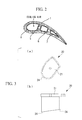
- Fig. 2 is a plan view showing relevant portions in Fig. 1 ;
- FIG. 3 is a diagram showing a front-insert electrode that forms a gas-turbine-stator-vane insert removing device according to an embodiment of the present invention, where (a) is a plan view thereof and (b) is a side view thereof;
- Fig. 4 is a diagram showing a middle-insert electrode that forms the gas-turbine-stator-vane insert removing device according to the embodiment of the present invention, where (a) is a plan view thereof and (b) is a side view thereof;
- Fig. 4 is a diagram showing a middle-insert electrode that forms the gas-turbine-stator-vane insert removing device according to the embodiment of the present invention, where (a) is a plan view thereof and (b) is a side view thereof;
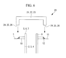
- FIG. 5 is a diagram showing a rear-insert electrode that forms the gas-turbine-stator-vane insert removing device according to the embodiment of the present invention, where (a) is a plan view thereof and (b) is a side view thereof; and Fig. 6 is a diagram showing relative relationships between welding metal and the front-insert electrode, the middle-insert electrode, and the rear-insert electrode.
- a gas-turbine stator vane 15 which is a gas-turbine stator vane to be applied to, for example, a 1500 °C-class gas turbine, is equipped with a blade surface (blade main unit) 1 provided with a front hollow hole 2, a middle hollow hole 3, and a rear hollow hole 4, and is configured so that, individually, a hollow front insert 5 is inserted into the front hollow hole 2, a middle insert 6 is inserted into the middle hollow hole 3, and a rear insert 7 is inserted into the rear hollow hole 4.
- numerous cooling-air jetting holes 8 having diameters of 0.1 mm to 0.5 mm are provided in each of the front insert 5, the middle insert 6, and the rear insert 7.
- one end of the front insert 5, the middle insert 6, and the rear insert 7 is provided with insert collars (flange portions) 10 along circumferential directions thereof, which protrude outward from insert outer circumferential surfaces 9, and the insert collars 10 and a stator-vane-outer-shroud non-gas path surface 11 of the blade surface 1 are connected by means of welding.
- the reference sign 12 in Fig. 6 indicates welding metal.
- the gas-turbine-stator-vane insert removing device (hereinafter, referred to as "insert removing device") 20 is an "electrical discharging machine" provided with a front-insert electrode 21, a middle-insert electrode 22, and a rear-insert electrode 23, wherein the welding metal 12 is removed by generating an arc discharge, which is repeated at a short cycle, between the blade surface 1 and the front-insert electrode 21, the middle-insert electrode 22, and the rear-insert electrode 23.
- the front-insert electrode 21 shown in Fig. 3 has the same plan-view shape as the plan-view shape of the welding metal 12 (see Fig.
- stator-vane-outer-shroud non-gas path surface 11 that surrounds the periphery of the front hollow hole 2, and also has a bottom surface 24 that matches a curved-surface shape of the stator-vane-outer-shroud non-gas path surface 11 which faces it during the electrical discharging (during removal work of the front insert).
- the middle-insert electrode 22 shown in Fig. 4 has the same plan-view shape as the plan-view shape of the welding metal 12 (see Fig. 6 ) that connects the insert collar 10 of the middle insert 6 and the stator-vane-outer-shroud non-gas path surface 11 that surrounds the periphery of the middle hollow hole 3 (has the same inner circumferential edge and outer circumferential edge as an inner circumferential edge and an outer circumferential edge of the welding metal 12), and also has a bottom surface 25 that matches the curved-surface shape of the stator-vane-outer-shroud non-gas path surface 11 which faces it during the electrical discharging (during removal work of the middle insert).
- the rear-insert electrode 23 shown in Fig. 5 has the same plan-view shape as the plan-view shape of the welding metal 12 (see Fig. 6 ) that connects the insert collar 10 of the rear insert 7 and the stator-vane-outer-shroud non-gas path surface 11 that surrounds the periphery of the rear hollow hole 4, and also has a bottom surface 26 that matches the curved-surface shape of the stator-vane-outer-shroud non-gas path surface 11 which faces it during the electrical discharging (during removal work of the front insert).
- the gas-turbine stator vane 15 from which the front insert 5, the middle insert 6, and the rear insert 7 are to be detached, is set at a predetermined position in the insert removing device 20.
- the front-insert electrode 21 and the welding metal 12 are aligned so that the bottom surface 24 of the front-insert electrode 21 faces the welding metal 12, which connects the insert collar 10 of the front insert 5 and the stator-vane-outer-shroud non-gas path surface 11 that surrounds the periphery of the front hollow hole 2, and, in addition, so that a predetermined gap (about 3 ⁇ m to 200 ⁇ m), which is also kept constant, is formed between the bottom surface 24 and the welding metal 12.
- the insert removing device 20 is activated to generate an arc discharge between the bottom surface 24 of the front-insert electrode 21 and the stator-vane-outer-shroud non-gas path surface 11 of the blade surface 1, thus removing the welding metal 12 by means of electrical discharge.
- the middle-insert electrode 22 and the welding metal 12 are aligned so that the bottom surface 25 of the middle-insert electrode 22 faces the welding metal 12, which connects the insert collar 10 of the middle insert 6 and the stator-vane-outer-shroud non-gas path surface 11 that surrounds the periphery of the middle hollow hole 3, and, in addition, so that the predetermined gap (about 3 ⁇ m to 200 ⁇ m), which is also kept constant, is formed between the bottom surface 25 and the welding metal 12.
- the insert removing device 20 is activated to generate the arc discharge between the bottom surface 25 of the middle-insert electrode 22 and the stator-vane-outer-shroud non-gas path surface 11 of the blade surface 1, thus removing the welding metal 12 by means of electrical discharge.
- the rear-insert electrode 23 and the welding metal 12 are aligned so that the bottom surface 26 of the rear-insert electrode 23 faces the welding metal 12, which connects the insert collar 10 of the rear insert 7 and the stator-vane-outer-shroud non-gas path surface 11 that surrounds the periphery of the rear hollow hole 4, and, in addition, so that the predetermined gap (about 3 ⁇ m to 200 ⁇ m), which is also kept constant, is formed between the bottom surface 26 and the welding metal 12.
- the insert removing device 20 is activated to generate the arc discharge between the bottom surface 26 of the rear-insert electrode 23 and the stator-vane-outer-shroud non-gas path surface 11 of the blade surface 1, thus removing the welding metal 12 by means of electrical discharge.
- the welding metal 12 is eliminated by using a grinding machine, such as a grinder, etc., such that the front insert 5 is taken out from the front hollow hole 2, the middle insert 6 is taken out from the middle hollow hole 3, and the rear insert 7 is taken out from the rear hollow hole 4.
- the gas-turbine stator vane 15, from which the front insert 5, the middle insert 6, and the rear insert 7 are to be detached, is set at the predetermined position in the insert removing device 20; the front-insert electrode 21, the middle-insert electrode 22, and the rear-insert electrode 23 are aligned with the welding metal 12 so that the bottom surface 24 of the front-insert electrode 21, the bottom surface 25 of the middle-insert electrode 22, and the bottom surface 26 of the rear-insert electrode 23 face the welding metal 12, and, in addition, so that the predetermined gaps (about 3 ⁇ m to 200 ⁇ m) are formed between the welding metal 12 and the bottom surface 24 of the front-insert electrode 21, the bottom surface 25 of the middle-insert electrode 22, and the bottom surface 26 of the rear-insert electrode 23; the insert removing device 20 is activated to generate the arc discharges between the stator-vane-outer-shroud
- the bottom surface 24 of the front-insert electrode 21, the bottom surface 25 of the middle-insert electrode 22, and the bottom surface 26 of the rear-insert electrode 23 have the shapes that match the curved-surface shape of the stator-vane-outer-shroud non-gas path surface 11, which faces them during the electrical discharging, and thus, the gaps between the welding metal 12 and the bottom surface 24 of the front-insert electrode 21, the bottom surface 25 of the middle-insert electrode 22, and the bottom surface 26 of the rear-insert electrode 23 are kept (substantially) constant in the circumferential direction; therefore, the intensity of the arc discharges generated between the stator-vane-outer-shroud non-gas path surface 11 and the bottom surface 24 of the front-insert electrode 21, the bottom surface 25 of the middle-insert electrode 22, and the bottom surface 26 of the rear-insert electrode 23
- the present invention is not limited to the above-described embodiment, and appropriate alterations and modifications are also possible as needed.
- the detachment in the above-described embodiment is performed in the order from the front insert 5, the middle insert 6, and the rear insert 7, the detachment may be performed in order starting from the rear insert 7, the middle insert 6, and the front insert 5, and the detachment order can be appropriately changed in consideration of work efficiency, etc.
- the inner circumferential edges of the bottom surface 24 of the front-insert electrode 21, the bottom surface 25 of the middle-insert electrode 22, and the bottom surface 26 of the rear-insert electrode 23 are set to be the same as (to match) the inner circumferential edge of the welding metal 12; however, it is more preferable if the inner circumferential edges of the bottom surface 24 of the front-insert electrode 21, the bottom surface 25 of the middle-insert electrode 22, and the bottom surface 26 of the rear-insert electrode 23 are set so as to be positioned 1 mm to 2 mm inside the inner circumferential edge of the welding metal 12.
Landscapes
- Engineering & Computer Science (AREA)
- Mechanical Engineering (AREA)
- General Engineering & Computer Science (AREA)
- Chemical & Material Sciences (AREA)
- Combustion & Propulsion (AREA)
- Electrical Discharge Machining, Electrochemical Machining, And Combined Machining (AREA)
- Arc Welding In General (AREA)
- Manufacture Of Motors, Generators (AREA)
- Turbine Rotor Nozzle Sealing (AREA)
Abstract
Description
- The present invention relates to a gas-turbine-stator-vane insert removing device employed when detaching an insert from a gas-turbine stator vane and a method of removing a gas-turbine-stator-vane insert.
- In the related art, for example, when detaching an insert from a blade surface (blade main unit) of a gas-turbine stator vane disclosed in
Patent Literature 1, welding metal that connects an insert collar that protrudes outward from an outer circumferential surface of the insert and a stator-vane-outer-shroud non-gas path surface that surrounds the periphery of the insert collar is worn off with a grinding machine, such as a grinder, etc., and the insert is taken out from a corresponding hollow hole, thus separating the insert from the blade surface.
Note that, from the view points of environment and cost, the blade surface from which the insert is detached and the insert detached from the blade surface are subjected to appropriate refurbishing, etc., as needed, and reassembled to be subsequently reused as a gas-turbine stator vane. - {PTL 1} Japanese Unexamined Patent Application, Publication No.
Hei 11-2103 - However, with the method in the related art, in which the welding metal is worn off by using a grinding machine, such as a grinder, etc., the welding metal must be carefully worn off so as not to damage the outer circumferential surfaces of inserts; in addition, even for a person with well-developed skill, it is extremely difficult to wear off welding metal at narrow portions between adjacent inserts; and thus, there is a problem in that the work of detaching (removing) the inserts requires a large amount of time and effort, thus resulting in poor work efficiency.
- The present invention has been conceived in light of the above-described circumstances, and an object thereof is to provide a gas-turbine-stator-vane insert removing device and a method of removing a gas-turbine-stator-vane insert with which it is possible even for a person without well-developed skill to easily and quickly detach an insert from a blade surface of a gas-turbine stator vane.
- In order to solve the above-described problems, the present invention employs the following solutions.
A gas-turbine-stator-vane insert removing device according to a first aspect of the present invention is a gas-turbine-stator-vane insert removing device with which welding metal that connects an insert collar, which protrudes outward from an outer circumferential surface of an insert, and a stator-vane-outer-shroud non-gas path surface, which surrounds the periphery of the insert collar, is removed by means of an arc discharge repeated at a short cycle between an electrode and a blade surface of a gas-turbine stator vane, wherein a bottom surface of the electrode has the same plan-view shape as a plan-view shape of the welding metal. - With the gas-turbine-stator-vane insert removing device according to the first aspect of the present invention, the gas-turbine stator vane, from which the insert is to be detached, is set at the predetermined position in the gas-turbine-stator-vane insert removing device; the electrode and the welding metal are aligned so that the bottom surface of the electrode faces the welding metal, and, in addition, so that a predetermined gap is formed between the bottom surface of the electrode and the welding metal; and the welding metal is removed by means of an electrical discharge by activating the gas-turbine-stator-vane insert removing device and by generating an arc discharge between the bottom surface of the electrode and the stator-vane-outer-shroud non-gas path surface.
Accordingly, it is possible even for a person without well-developed skill to easily and quickly detach the insert from the gas-turbine stator vane. - In the above-described gas-turbine-stator-vane insert removing device, it is more preferable that the bottom surface be shaped so as to match a curved-shape surface of the stator-vane-outer-shroud non-gas path surface of the blade surface which faces the bottom surface during electrical discharging.
- With such a gas-turbine-stator-vane insert removing device, because the gap between the bottom surface of the electrode and the welding metal is kept (substantially) constant in the circumferential direction, the intensity of the arc discharge generated between the bottom surface of the electrode and the stator-vane-outer-shroud non-gas path surface can be kept (substantially) constant in the circumferential direction, and the welding metal can be (substantially) evenly removed in the circumferential direction.
- In the above-described gas-turbine-stator-vane insert removing device, it is more preferable that an inner circumferential edge of the bottom surface be formed so as to be positioned 1 mm to 2 mm inside an inner circumferential edge of the welding metal.
- With such a gas-turbine-stator-vane insert removing device, because a circumferential edge of the insert collar melted into the welding metal is exposed, thus disengaging the connection between the insert collar and the stator-vane-outer-shroud non-gas path surface, it is possible to eliminate work such as eliminating (removing) the connecting portion between the insert collar and the stator-vane-outer-shroud non-gas path surface by using a grinding machine, such as a grinder, etc.; the work time can be shortened; and the work efficiency can be further improved.
- A method of removing a gas-turbine-stator-vane insert according a second aspect of the present invention is a method of removing a gas-turbine-stator-vane insert performed by employing the gas-turbine-stator-vane insert removing device according to any one of
Claims 1 to 3, including a step of setting a gas-turbine stator vane, from which an insert is to be detached, at a predetermined position in the gas-turbine-stator-vane insert removing device; a step of aligning the electrode and the welding metal so that the bottom surface of the electrode faces the welding metal, and, in addition, so that a predetermined gap is formed between the bottom surface of the electrode and the welding metal; a step of removing the welding metal by means of electrical discharge by activating the gas-turbine-stator-vane insert removing device and by generating an arc discharge between the bottom surface of the electrode and the stator-vane-outer-shroud non-gas path surface; and a step of separating the insert from the blade surface. - With the method of removing a gas-turbine-stator-vane insert according to the second aspect of the present invention, the gas-turbine stator vane, from which the insert is to be detached, is set at the predetermined position in the gas-turbine-stator-vane insert removing device; the electrode and the welding metal are aligned so that the bottom surface of the electrode faces the welding metal, and, in addition, so that a predetermined gap is formed between the bottom surface of the electrode and the welding metal; and the welding metal is removed by means of electrical discharge by activating the gas-turbine-stator-vane insert removing device and by generating the arc discharge between the bottom surface of the electrode and the stator-vane-outer-shroud non-gas path surface.
Accordingly, it is possible even for a person without well-developed skill to easily and quickly detach the insert from the gas-turbine stator vane. - The gas-turbine-stator-vane insert removing device and the method of removing a gas-turbine-stator-vane insert according to the present invention afford an advantage in that it is possible even for a person without well-developed skill to easily and quickly detach an insert from a blade surface of a gas-turbine stator vane.
-
-
Fig. 1 is an external view of a gas-turbine stator vane according to the present invention, where (a) is an overall view and (b) is a perspective view showing a state in which an insert is taken out from a hollow hole. -
Fig. 2 is a plan view showing relevant portions inFig. 1 . -
Fig. 3 is a diagram showing a front-insert electrode that forms a gas-turbine-stator-vane insert removing device according to an embodiment of the present invention, where (a) is a plan view thereof and (b) is a side view thereof. -
Fig. 4 is a diagram showing a middle-insert electrode that forms the gas-turbine-stator-vane insert removing device according to the embodiment of the present invention, where (a) is a plan view thereof and (b) is a side view thereof. -
Fig. 5 is a diagram showing a rear-insert electrode that forms the gas-turbine-stator-vane insert removing device according to the embodiment of the present invention, where (a) is a plan view thereof and (b) is a side view thereof. -
Fig. 6 is a diagram showing relative relationships between welding metal and the front-insert electrode, the middle-insert electrode, and the rear-insert electrode. - A gas-turbine-stator-vane insert removing device and a method of removing a gas-turbine-stator-vane insert according to an embodiment of the present invention will be described below with reference to
Figs. 1 to 6 .
Fig. 1 is an external view of a gas-turbine stator vane according to the present invention, where (a) is an overall view and (b) is a perspective view showing a state in which an insert is taken out from a hollow hole;Fig. 2 is a plan view showing relevant portions inFig. 1 ;Fig. 3 is a diagram showing a front-insert electrode that forms a gas-turbine-stator-vane insert removing device according to an embodiment of the present invention, where (a) is a plan view thereof and (b) is a side view thereof;Fig. 4 is a diagram showing a middle-insert electrode that forms the gas-turbine-stator-vane insert removing device according to the embodiment of the present invention, where (a) is a plan view thereof and (b) is a side view thereof;Fig. 5 is a diagram showing a rear-insert electrode that forms the gas-turbine-stator-vane insert removing device according to the embodiment of the present invention, where (a) is a plan view thereof and (b) is a side view thereof; andFig. 6 is a diagram showing relative relationships between welding metal and the front-insert electrode, the middle-insert electrode, and the rear-insert electrode. - As shown in
Figs. 1 and2 , a gas-turbine stator vane 15 according to the present invention, which is a gas-turbine stator vane to be applied to, for example, a 1500 °C-class gas turbine, is equipped with a blade surface (blade main unit) 1 provided with a fronthollow hole 2, a middlehollow hole 3, and a rearhollow hole 4, and is configured so that, individually, ahollow front insert 5 is inserted into the fronthollow hole 2, amiddle insert 6 is inserted into the middlehollow hole 3, and arear insert 7 is inserted into the rearhollow hole 4. In addition, numerous cooling-air jetting holes 8 having diameters of 0.1 mm to 0.5 mm are provided in each of thefront insert 5, themiddle insert 6, and therear insert 7. In addition, as shown inFig. 6 , one end of thefront insert 5, themiddle insert 6, and therear insert 7 is provided with insert collars (flange portions) 10 along circumferential directions thereof, which protrude outward from insert outercircumferential surfaces 9, and theinsert collars 10 and a stator-vane-outer-shroudnon-gas path surface 11 of theblade surface 1 are connected by means of welding. Note that thereference sign 12 inFig. 6 indicates welding metal. - The gas-turbine-stator-vane insert removing device (hereinafter, referred to as "insert removing device") 20 according to this embodiment is an "electrical discharging machine" provided with a front-
insert electrode 21, a middle-insert electrode 22, and a rear-insert electrode 23, wherein thewelding metal 12 is removed by generating an arc discharge, which is repeated at a short cycle, between theblade surface 1 and the front-insert electrode 21, the middle-insert electrode 22, and the rear-insert electrode 23.
The front-insert electrode 21 shown inFig. 3 has the same plan-view shape as the plan-view shape of the welding metal 12 (seeFig. 6 ) that connects theinsert collar 10 of thefront insert 5 and the stator-vane-outer-shroudnon-gas path surface 11 that surrounds the periphery of the fronthollow hole 2, and also has abottom surface 24 that matches a curved-surface shape of the stator-vane-outer-shroudnon-gas path surface 11 which faces it during the electrical discharging (during removal work of the front insert). - The middle-
insert electrode 22 shown inFig. 4 has the same plan-view shape as the plan-view shape of the welding metal 12 (seeFig. 6 ) that connects theinsert collar 10 of themiddle insert 6 and the stator-vane-outer-shroudnon-gas path surface 11 that surrounds the periphery of the middle hollow hole 3 (has the same inner circumferential edge and outer circumferential edge as an inner circumferential edge and an outer circumferential edge of the welding metal 12), and also has abottom surface 25 that matches the curved-surface shape of the stator-vane-outer-shroudnon-gas path surface 11 which faces it during the electrical discharging (during removal work of the middle insert).
The rear-insert electrode 23 shown inFig. 5 has the same plan-view shape as the plan-view shape of the welding metal 12 (seeFig. 6 ) that connects theinsert collar 10 of therear insert 7 and the stator-vane-outer-shroudnon-gas path surface 11 that surrounds the periphery of the rearhollow hole 4, and also has abottom surface 26 that matches the curved-surface shape of the stator-vane-outer-shroudnon-gas path surface 11 which faces it during the electrical discharging (during removal work of the front insert). - Next, the method of removing a gas-turbine-stator-vane insert (hereinafter, referred to as "insert removal method") according to this embodiment will be described.
First of all, the gas-turbine stator vane 15, from which the front insert 5, themiddle insert 6, and therear insert 7 are to be detached, is set at a predetermined position in theinsert removing device 20. - Next, the front-
insert electrode 21 and thewelding metal 12 are aligned so that thebottom surface 24 of the front-insert electrode 21 faces thewelding metal 12, which connects theinsert collar 10 of thefront insert 5 and the stator-vane-outer-shroudnon-gas path surface 11 that surrounds the periphery of the fronthollow hole 2, and, in addition, so that a predetermined gap (about 3 µm to 200 µm), which is also kept constant, is formed between thebottom surface 24 and thewelding metal 12.
Subsequently, theinsert removing device 20 is activated to generate an arc discharge between thebottom surface 24 of the front-insert electrode 21 and the stator-vane-outer-shroudnon-gas path surface 11 of theblade surface 1, thus removing thewelding metal 12 by means of electrical discharge. - Next, the middle-
insert electrode 22 and thewelding metal 12 are aligned so that thebottom surface 25 of the middle-insert electrode 22 faces thewelding metal 12, which connects theinsert collar 10 of themiddle insert 6 and the stator-vane-outer-shroudnon-gas path surface 11 that surrounds the periphery of the middlehollow hole 3, and, in addition, so that the predetermined gap (about 3 µm to 200 µm), which is also kept constant, is formed between thebottom surface 25 and thewelding metal 12.
Subsequently, theinsert removing device 20 is activated to generate the arc discharge between thebottom surface 25 of the middle-insert electrode 22 and the stator-vane-outer-shroudnon-gas path surface 11 of theblade surface 1, thus removing thewelding metal 12 by means of electrical discharge. - Next, the rear-
insert electrode 23 and thewelding metal 12 are aligned so that thebottom surface 26 of the rear-insert electrode 23 faces thewelding metal 12, which connects theinsert collar 10 of therear insert 7 and the stator-vane-outer-shroudnon-gas path surface 11 that surrounds the periphery of the rearhollow hole 4, and, in addition, so that the predetermined gap (about 3 µm to 200 µm), which is also kept constant, is formed between thebottom surface 26 and thewelding metal 12.
Subsequently, theinsert removing device 20 is activated to generate the arc discharge between thebottom surface 26 of the rear-insert electrode 23 and the stator-vane-outer-shroudnon-gas path surface 11 of theblade surface 1, thus removing thewelding metal 12 by means of electrical discharge. - Then, the gas-
turbine stator vane 15, in which thewelding metal 12 that connects theinsert collar 10 of thefront insert 5 and the stator-vane-outer-shroudnon-gas path surface 11, which surrounds the periphery of the fronthollow hole 2, thewelding metal 12 that connects theinsert collar 10 of themiddle insert 6 and the stator-vane-outer-shroudnon-gas path surface 11, which surrounds the periphery of the middlehollow hole 3, and thewelding metal 12 that connects theinsert collar 10 of therear insert 7 and the stator-vane-outer-shroudnon-gas path surface 11, which surrounds the periphery of the rearhollow hole 4, have been removed, is taken out from theinsert removing device 20, and thefront insert 5 is taken out from the fronthollow hole 2, themiddle insert 6 is taken out from the middlehollow hole 3, and therear insert 7 is taken out from the rearhollow hole 4, thus separating thefront insert 5, themiddle insert 6, and therear insert 7 from theblade surface 1.
Note that, in the case in where it is difficult to take out thefront insert 5 from the fronthollow hole 2, to take out the middle insert from the middlehollow hole 3, and to take out therear insert 7 from the rearhollow hole 4 due to thewelding metal 12 remaining after the electrical discharge, thewelding metal 12 is eliminated by using a grinding machine, such as a grinder, etc., such that thefront insert 5 is taken out from the fronthollow hole 2, themiddle insert 6 is taken out from the middlehollow hole 3, and therear insert 7 is taken out from the rearhollow hole 4. - In the insert removing device and the insert removing method according to this embodiment, the gas-
turbine stator vane 15, from which the front insert 5, themiddle insert 6, and therear insert 7 are to be detached, is set at the predetermined position in theinsert removing device 20; the front-insert electrode 21, the middle-insert electrode 22, and the rear-insert electrode 23 are aligned with thewelding metal 12 so that thebottom surface 24 of the front-insert electrode 21, thebottom surface 25 of the middle-insert electrode 22, and thebottom surface 26 of the rear-insert electrode 23 face thewelding metal 12, and, in addition, so that the predetermined gaps (about 3 µm to 200 µm) are formed between thewelding metal 12 and thebottom surface 24 of the front-insert electrode 21, thebottom surface 25 of the middle-insert electrode 22, and thebottom surface 26 of the rear-insert electrode 23; theinsert removing device 20 is activated to generate the arc discharges between the stator-vane-outer-shroudnon-gas path surface 11 and thebottom surface 24 of the front-insert electrode 21, thebottom surface 25 of the middle-insert electrode 22, and thebottom surface 26 of the rear-insert electrode 23; and thereby, thewelding metal 12 is removed by means of electrical discharge.
Accordingly, it is possible even for a person without well-developed skill to easily and quickly detach thefront insert 5, themiddle insert 6, and therear insert 7 from theblade surface 1 of the gas-turbine stator vane 15. - In addition, with the gas-turbine-stator-vane insert removing device according to this embodiment, the
bottom surface 24 of the front-insert electrode 21, thebottom surface 25 of the middle-insert electrode 22, and thebottom surface 26 of the rear-insert electrode 23 have the shapes that match the curved-surface shape of the stator-vane-outer-shroudnon-gas path surface 11, which faces them during the electrical discharging, and thus, the gaps between thewelding metal 12 and thebottom surface 24 of the front-insert electrode 21, thebottom surface 25 of the middle-insert electrode 22, and thebottom surface 26 of the rear-insert electrode 23 are kept (substantially) constant in the circumferential direction; therefore, the intensity of the arc discharges generated between the stator-vane-outer-shroudnon-gas path surface 11 and thebottom surface 24 of the front-insert electrode 21, thebottom surface 25 of the middle-insert electrode 22, and thebottom surface 26 of the rear-insert electrode 23 can be kept (substantially) constant in the circumferential direction, and thewelding metal 12 can be (substantially) evenly removed in the circumferential direction. - Note that the present invention is not limited to the above-described embodiment, and appropriate alterations and modifications are also possible as needed.
For example, although the detachment in the above-described embodiment is performed in the order from thefront insert 5, themiddle insert 6, and therear insert 7, the detachment may be performed in order starting from therear insert 7, themiddle insert 6, and thefront insert 5, and the detachment order can be appropriately changed in consideration of work efficiency, etc. - In addition, in the above-described embodiment, the inner circumferential edges of the
bottom surface 24 of the front-insert electrode 21, thebottom surface 25 of the middle-insert electrode 22, and thebottom surface 26 of the rear-insert electrode 23 are set to be the same as (to match) the inner circumferential edge of thewelding metal 12; however, it is more preferable if the inner circumferential edges of thebottom surface 24 of the front-insert electrode 21, thebottom surface 25 of the middle-insert electrode 22, and thebottom surface 26 of the rear-insert electrode 23 are set so as to be positioned 1 mm to 2 mm inside the inner circumferential edge of thewelding metal 12.
Accordingly, because the circumferential edges of theinsert collars 10 melted into thewelding metal 12 are exposed, thus disengaging the connections between theinsert collars 10 and the stator-vane-outer-shroudnon-gas path surface 11, it is possible to eliminate work such as eliminating (removing) the connecting portions between theinsert collars 10 and the stator-vane-outer-shroudnon-gas path surface 11 by using a grinding machine, such as a grinder, etc.; work time can be shortened; and the work efficiency can be further improved. - Furthermore, when applying, as needed, appropriate refurbishing, etc., to the
blade surface 1, from which the front insert 5, themiddle insert 6, and therear insert 7 have been detached, and to thefront insert 5, themiddle insert 6, and therear insert 7, which have been detached from theblade surface 1, and when reassembling them to be reused as a gas-turbine stator vane, it is desirable that the front insert 5, the middle insert 6, and therear insert 7 be attached to the original blade surface 1 (into which they had been inserted).
By doing so, even in the case in which deformation has occurred in thefront insert 5, themiddle insert 6, and therear insert 7 themselves, reuse is made possible by attaching them to theoriginal blade surface 1, thus making it possible to prevent thefront insert 5, themiddle insert 6, therear insert 7, and the gas-turbine stator vane 15 from being discarded, and the running cost can be reduced. -
- 1 blade surface
- 2 front hollow hole
- 3 middle hollow hole
- 4 rear hollow hole
- 5 front insert
- 6 middle insert
- 7 rear insert
- 8 cooling-air jetting hole
- 9 insert outer circumferential surface
- 10 insert collar
- 11 stator-vane-outer-shroud non-gas path surface
- 12 welding metal
- 15 gas-turbine stator vane
- 20 insert removing device (gas-turbine-stator-vane insert removing device)
- 21 front-insert electrode
- 22 middle-insert electrode
- 23 rear-insert electrode
- 24 front-insert-electrode bottom surface
- 25 middle-insert-electrode bottom surface
- 26 rear-insert-electrode bottom surface
Claims (4)
- A gas-turbine-stator-vane insert removing device with which welding metal that connects an insert collar, which protrudes outward from an outer circumferential surface of an insert, and a stator-vane-outer-shroud non-gas path surface, which surrounds the periphery of the insert collar, is removed by means of an arc discharge repeated at a short cycle between an electrode and a blade surface of a gas-turbine stator vane, wherein
a bottom surface of the electrode has the same plan-view shape as a plan-view shape of the welding metal. - A gas-turbine-stator-vane insert removing device according to Claim 1, wherein the bottom surface has a shape that matches a curved-shape surface of the stator-vane-outer-shroud non-gas path surface of the blade surface which faces the bottom surface during electrical discharging.
- A gas-turbine-stator-vane insert removing device according to Claim 1 or 2, wherein an inner circumferential edge of the bottom surface is formed so as to be positioned 1 mm to 2 mm inside an inner circumferential edge of the welding metal.
- A method of removing a gas-turbine-stator-vane insert performed by employing the gas-turbine-stator-vane insert removing device according to any one of Claims 1 to 3, comprising:a step of setting a gas-turbine stator vane, from which an insert is to be detached, at a predetermined position in the gas-turbine-stator-vane insert removing device;a step of aligning the electrode and the welding metal so that the bottom surface of the electrode faces the welding metal, and, in addition, so that a predetermined gap is formed between the bottom surface of the electrode and the welding metal;a step of removing the welding metal by means of electrical discharge by activating the gas-turbine-stator-vane insert removing device and by generating an arc discharge between the bottom surface of the electrode and the stator-vane-outer-shroud non-gas path surface; anda step of separating the insert from the blade surface.
Applications Claiming Priority (2)
| Application Number | Priority Date | Filing Date | Title |
|---|---|---|---|
| JP2010008175A JP5422407B2 (en) | 2010-01-18 | 2010-01-18 | Gas turbine stationary blade insert removal apparatus and gas turbine stationary blade insert removal method |
| PCT/JP2011/050092 WO2011086962A1 (en) | 2010-01-18 | 2011-01-06 | Insert removal device for gas turbine stationary blade and insert removal method for gas turbine stationary blade |
Publications (3)
| Publication Number | Publication Date |
|---|---|
| EP2527619A1 true EP2527619A1 (en) | 2012-11-28 |
| EP2527619A4 EP2527619A4 (en) | 2014-08-20 |
| EP2527619B1 EP2527619B1 (en) | 2016-03-30 |
Family
ID=44304235
Family Applications (1)
| Application Number | Title | Priority Date | Filing Date |
|---|---|---|---|
| EP11732832.8A Active EP2527619B1 (en) | 2010-01-18 | 2011-01-06 | Insert removal device for gas turbine stationary blade and insert removal method for gas turbine stationary blade |
Country Status (6)
| Country | Link |
|---|---|
| US (1) | US8806745B2 (en) |
| EP (1) | EP2527619B1 (en) |
| JP (1) | JP5422407B2 (en) |
| KR (1) | KR101280724B1 (en) |
| CN (1) | CN102575581B (en) |
| WO (1) | WO2011086962A1 (en) |
Families Citing this family (6)
| Publication number | Priority date | Publication date | Assignee | Title |
|---|---|---|---|---|
| CN104384640B (en) * | 2014-10-27 | 2016-08-17 | 沈阳黎明航空发动机(集团)有限责任公司 | A kind of method removing aero-engine stator assembly damaged blade |
| CN105328396B (en) * | 2015-11-26 | 2017-09-12 | 沈阳黎明航空发动机(集团)有限责任公司 | A kind of compressor stator blade unit replacement blade restorative procedure |
| FR3062327B1 (en) * | 2017-01-30 | 2019-04-19 | Safran Aircraft Engines | PROCESS FOR REMOVING A METALLIC ELEMENT ADHESIVE TO A COMPOUND MATERIAL ELEMENT |
| JP7232035B2 (en) * | 2018-12-18 | 2023-03-02 | 三菱重工業株式会社 | Gas turbine stator blades and gas turbines |
| CN112548485A (en) * | 2020-10-27 | 2021-03-26 | 中国船舶重工集团公司第七0三研究所 | Non-impact press-fitting method for stationary blade ring of gas turbine |
| CN120002310B (en) * | 2025-03-03 | 2026-05-29 | 中国华电科工集团有限公司 | Blade root metal part separation equipment and method |
Family Cites Families (14)
| Publication number | Priority date | Publication date | Assignee | Title |
|---|---|---|---|---|
| US4141124A (en) * | 1977-08-29 | 1979-02-27 | United Technologies Corporation | Method and apparatus for removing one or more vanes from a gas turbine compressor stator |
| JPS5976671A (en) * | 1982-10-26 | 1984-05-01 | Matsushita Electric Ind Co Ltd | Working method of metal |
| JPS62246424A (en) | 1986-04-16 | 1987-10-27 | Mitsubishi Heavy Ind Ltd | Wire cut electric discharge machining method |
| DE3720266A1 (en) | 1987-06-19 | 1988-12-29 | Bw Hydraulik Gmbh | ELECTROHYDRAULIC CONTROL SYSTEM |
| US4819313A (en) | 1988-06-03 | 1989-04-11 | Westinghouse Electric Corp. | Method of salvaging stationary blades of a steam turbine |
| US5560841A (en) * | 1994-10-11 | 1996-10-01 | United Technologies Corporation | Stator vane extraction |
| GB9700819D0 (en) * | 1997-01-16 | 1997-03-05 | Gkn Westland Helicopters Ltd | Method of and apparatus for removing a metallic component from attachmet to a helicopter blade |
| US5797725A (en) * | 1997-05-23 | 1998-08-25 | Allison Advanced Development Company | Gas turbine engine vane and method of manufacture |
| JP3897402B2 (en) | 1997-06-13 | 2007-03-22 | 三菱重工業株式会社 | Gas turbine stationary blade insert insertion structure and method |
| EP1057565B1 (en) | 1999-06-02 | 2006-03-29 | General Electric Company | Post-cast EDM method for reducing the thickness of a turbine nozzle wall |
| DE60321971D1 (en) | 2003-05-07 | 2008-08-14 | Snecma | MACHINE STATION AND ASSEMBLY AND DISASSEMBLY METHOD |
| CN1826431B (en) * | 2003-06-11 | 2011-12-28 | 石川岛播磨重工业株式会社 | Repair and manufacturing method of mechanical parts and manufacturing method of repaired mechanical parts |
| US7798773B2 (en) * | 2007-08-06 | 2010-09-21 | United Technologies Corporation | Airfoil replacement repair |
| US20130206737A1 (en) * | 2012-02-09 | 2013-08-15 | General Electric Company | System and method for removing a stator vane |
-
2010
- 2010-01-18 JP JP2010008175A patent/JP5422407B2/en not_active Expired - Fee Related
-
2011
- 2011-01-06 US US13/390,205 patent/US8806745B2/en active Active
- 2011-01-06 WO PCT/JP2011/050092 patent/WO2011086962A1/en not_active Ceased
- 2011-01-06 KR KR1020127004343A patent/KR101280724B1/en not_active Expired - Fee Related
- 2011-01-06 CN CN201180003511.3A patent/CN102575581B/en active Active
- 2011-01-06 EP EP11732832.8A patent/EP2527619B1/en active Active
Also Published As
| Publication number | Publication date |
|---|---|
| KR101280724B1 (en) | 2013-07-01 |
| JP2011144781A (en) | 2011-07-28 |
| US8806745B2 (en) | 2014-08-19 |
| CN102575581A (en) | 2012-07-11 |
| US20120138581A1 (en) | 2012-06-07 |
| EP2527619A4 (en) | 2014-08-20 |
| CN102575581B (en) | 2014-05-14 |
| KR20120069666A (en) | 2012-06-28 |
| JP5422407B2 (en) | 2014-02-19 |
| WO2011086962A1 (en) | 2011-07-21 |
| EP2527619B1 (en) | 2016-03-30 |
Similar Documents
| Publication | Publication Date | Title |
|---|---|---|
| EP2527619B1 (en) | Insert removal device for gas turbine stationary blade and insert removal method for gas turbine stationary blade | |
| US8544173B2 (en) | Turbine nozzle biform repair | |
| US10633977B2 (en) | Blade, gas turbine equipped with same, and blade manufacturing method | |
| EP2025864A2 (en) | Airfoil replacement repair | |
| US9962797B2 (en) | Repair method for cast steel member | |
| US8191898B2 (en) | Brush seal assembly | |
| US20140068939A1 (en) | Method for manufacturing an airfoil | |
| TW201427795A (en) | Method and device for setting a predetermined radial gap width for rotor blades of a turbomachine | |
| JP2015527529A (en) | Template for forming cooling passages in turbine engine components | |
| CA2674569C (en) | Method and device for pin removal in a confined space | |
| CN111094721B (en) | Method for manufacturing turbine blade and turbine blade | |
| US20230347457A1 (en) | Method for repairing a damaged leading or trailing edge region of a metallic turbine blade | |
| CN101224510A (en) | Milling cutter recovery method | |
| CN117120691B (en) | Half arrowhead for the corner of the bucket | |
| CN101514640A (en) | Rotor of turbomachine and method for replacing rotor blades of the rotor | |
| EP3170617B1 (en) | Method for resistance welding of a pad to a surface | |
| US10612419B2 (en) | Steam turbine | |
| US20240017362A1 (en) | Method for manufacturing a turbomachine compressor blade by compacting | |
| KR20110034483A (en) | Bite holder | |
| IT202100010535A1 (en) | A SHREDDER HEAD | |
| EP2944793A1 (en) | Method for repairing plate-shaped member, plate-shaped member, combustor, split ring, and gas turbine | |
| JP2010141013A (en) | Composite substrate | |
| WO2017110465A1 (en) | Blade removal method, device and jig for executing said method, and blade set comprising said device |
Legal Events
| Date | Code | Title | Description |
|---|---|---|---|
| PUAI | Public reference made under article 153(3) epc to a published international application that has entered the european phase |
Free format text: ORIGINAL CODE: 0009012 |
|
| 17P | Request for examination filed |
Effective date: 20120215 |
|
| AK | Designated contracting states |
Kind code of ref document: A1 Designated state(s): AL AT BE BG CH CY CZ DE DK EE ES FI FR GB GR HR HU IE IS IT LI LT LU LV MC MK MT NL NO PL PT RO RS SE SI SK SM TR |
|
| DAX | Request for extension of the european patent (deleted) | ||
| A4 | Supplementary search report drawn up and despatched |
Effective date: 20140717 |
|
| RIC1 | Information provided on ipc code assigned before grant |
Ipc: F02C 7/00 20060101AFI20140711BHEP Ipc: F01D 9/02 20060101ALI20140711BHEP Ipc: F02C 7/18 20060101ALI20140711BHEP Ipc: F01D 25/00 20060101ALI20140711BHEP |
|
| GRAP | Despatch of communication of intention to grant a patent |
Free format text: ORIGINAL CODE: EPIDOSNIGR1 |
|
| RAP1 | Party data changed (applicant data changed or rights of an application transferred) |
Owner name: MITSUBISHI HITACHI POWER SYSTEMS, LTD. |
|
| INTG | Intention to grant announced |
Effective date: 20150311 |
|
| RAP1 | Party data changed (applicant data changed or rights of an application transferred) |
Owner name: MITSUBISHI HITACHI POWER SYSTEMS, LTD. |
|
| GRAS | Grant fee paid |
Free format text: ORIGINAL CODE: EPIDOSNIGR3 |
|
| GRAP | Despatch of communication of intention to grant a patent |
Free format text: ORIGINAL CODE: EPIDOSNIGR1 |
|
| GRAJ | Information related to disapproval of communication of intention to grant by the applicant or resumption of examination proceedings by the epo deleted |
Free format text: ORIGINAL CODE: EPIDOSDIGR1 |
|
| GRAP | Despatch of communication of intention to grant a patent |
Free format text: ORIGINAL CODE: EPIDOSNIGR1 |
|
| INTG | Intention to grant announced |
Effective date: 20150715 |
|
| INTG | Intention to grant announced |
Effective date: 20150728 |
|
| GRAA | (expected) grant |
Free format text: ORIGINAL CODE: 0009210 |
|
| AK | Designated contracting states |
Kind code of ref document: B1 Designated state(s): AL AT BE BG CH CY CZ DE DK EE ES FI FR GB GR HR HU IE IS IT LI LT LU LV MC MK MT NL NO PL PT RO RS SE SI SK SM TR |
|
| REG | Reference to a national code |
Ref country code: GB Ref legal event code: FG4D |
|
| REG | Reference to a national code |
Ref country code: CH Ref legal event code: EP |
|
| REG | Reference to a national code |
Ref country code: AT Ref legal event code: REF Ref document number: 785668 Country of ref document: AT Kind code of ref document: T Effective date: 20160415 |
|
| REG | Reference to a national code |
Ref country code: IE Ref legal event code: FG4D |
|
| REG | Reference to a national code |
Ref country code: DE Ref legal event code: R096 Ref document number: 602011024646 Country of ref document: DE |
|
| REG | Reference to a national code |
Ref country code: LT Ref legal event code: MG4D |
|
| PG25 | Lapsed in a contracting state [announced via postgrant information from national office to epo] |
Ref country code: FI Free format text: LAPSE BECAUSE OF FAILURE TO SUBMIT A TRANSLATION OF THE DESCRIPTION OR TO PAY THE FEE WITHIN THE PRESCRIBED TIME-LIMIT Effective date: 20160330 Ref country code: NO Free format text: LAPSE BECAUSE OF FAILURE TO SUBMIT A TRANSLATION OF THE DESCRIPTION OR TO PAY THE FEE WITHIN THE PRESCRIBED TIME-LIMIT Effective date: 20160630 Ref country code: HR Free format text: LAPSE BECAUSE OF FAILURE TO SUBMIT A TRANSLATION OF THE DESCRIPTION OR TO PAY THE FEE WITHIN THE PRESCRIBED TIME-LIMIT Effective date: 20160330 Ref country code: GR Free format text: LAPSE BECAUSE OF FAILURE TO SUBMIT A TRANSLATION OF THE DESCRIPTION OR TO PAY THE FEE WITHIN THE PRESCRIBED TIME-LIMIT Effective date: 20160701 |
|
| REG | Reference to a national code |
Ref country code: NL Ref legal event code: MP Effective date: 20160330 |
|
| REG | Reference to a national code |
Ref country code: AT Ref legal event code: MK05 Ref document number: 785668 Country of ref document: AT Kind code of ref document: T Effective date: 20160330 |
|
| PG25 | Lapsed in a contracting state [announced via postgrant information from national office to epo] |
Ref country code: LT Free format text: LAPSE BECAUSE OF FAILURE TO SUBMIT A TRANSLATION OF THE DESCRIPTION OR TO PAY THE FEE WITHIN THE PRESCRIBED TIME-LIMIT Effective date: 20160330 Ref country code: RS Free format text: LAPSE BECAUSE OF FAILURE TO SUBMIT A TRANSLATION OF THE DESCRIPTION OR TO PAY THE FEE WITHIN THE PRESCRIBED TIME-LIMIT Effective date: 20160330 Ref country code: LV Free format text: LAPSE BECAUSE OF FAILURE TO SUBMIT A TRANSLATION OF THE DESCRIPTION OR TO PAY THE FEE WITHIN THE PRESCRIBED TIME-LIMIT Effective date: 20160330 Ref country code: SE Free format text: LAPSE BECAUSE OF FAILURE TO SUBMIT A TRANSLATION OF THE DESCRIPTION OR TO PAY THE FEE WITHIN THE PRESCRIBED TIME-LIMIT Effective date: 20160330 |
|
| PG25 | Lapsed in a contracting state [announced via postgrant information from national office to epo] |
Ref country code: NL Free format text: LAPSE BECAUSE OF FAILURE TO SUBMIT A TRANSLATION OF THE DESCRIPTION OR TO PAY THE FEE WITHIN THE PRESCRIBED TIME-LIMIT Effective date: 20160330 |
|
| PG25 | Lapsed in a contracting state [announced via postgrant information from national office to epo] |
Ref country code: EE Free format text: LAPSE BECAUSE OF FAILURE TO SUBMIT A TRANSLATION OF THE DESCRIPTION OR TO PAY THE FEE WITHIN THE PRESCRIBED TIME-LIMIT Effective date: 20160330 Ref country code: IS Free format text: LAPSE BECAUSE OF FAILURE TO SUBMIT A TRANSLATION OF THE DESCRIPTION OR TO PAY THE FEE WITHIN THE PRESCRIBED TIME-LIMIT Effective date: 20160730 Ref country code: PL Free format text: LAPSE BECAUSE OF FAILURE TO SUBMIT A TRANSLATION OF THE DESCRIPTION OR TO PAY THE FEE WITHIN THE PRESCRIBED TIME-LIMIT Effective date: 20160330 |
|
| PG25 | Lapsed in a contracting state [announced via postgrant information from national office to epo] |
Ref country code: PT Free format text: LAPSE BECAUSE OF FAILURE TO SUBMIT A TRANSLATION OF THE DESCRIPTION OR TO PAY THE FEE WITHIN THE PRESCRIBED TIME-LIMIT Effective date: 20160801 Ref country code: RO Free format text: LAPSE BECAUSE OF FAILURE TO SUBMIT A TRANSLATION OF THE DESCRIPTION OR TO PAY THE FEE WITHIN THE PRESCRIBED TIME-LIMIT Effective date: 20160330 Ref country code: AT Free format text: LAPSE BECAUSE OF FAILURE TO SUBMIT A TRANSLATION OF THE DESCRIPTION OR TO PAY THE FEE WITHIN THE PRESCRIBED TIME-LIMIT Effective date: 20160330 Ref country code: SM Free format text: LAPSE BECAUSE OF FAILURE TO SUBMIT A TRANSLATION OF THE DESCRIPTION OR TO PAY THE FEE WITHIN THE PRESCRIBED TIME-LIMIT Effective date: 20160330 Ref country code: ES Free format text: LAPSE BECAUSE OF FAILURE TO SUBMIT A TRANSLATION OF THE DESCRIPTION OR TO PAY THE FEE WITHIN THE PRESCRIBED TIME-LIMIT Effective date: 20160330 Ref country code: SK Free format text: LAPSE BECAUSE OF FAILURE TO SUBMIT A TRANSLATION OF THE DESCRIPTION OR TO PAY THE FEE WITHIN THE PRESCRIBED TIME-LIMIT Effective date: 20160330 Ref country code: CZ Free format text: LAPSE BECAUSE OF FAILURE TO SUBMIT A TRANSLATION OF THE DESCRIPTION OR TO PAY THE FEE WITHIN THE PRESCRIBED TIME-LIMIT Effective date: 20160330 |
|
| PG25 | Lapsed in a contracting state [announced via postgrant information from national office to epo] |
Ref country code: BE Free format text: LAPSE BECAUSE OF FAILURE TO SUBMIT A TRANSLATION OF THE DESCRIPTION OR TO PAY THE FEE WITHIN THE PRESCRIBED TIME-LIMIT Effective date: 20160330 Ref country code: IT Free format text: LAPSE BECAUSE OF FAILURE TO SUBMIT A TRANSLATION OF THE DESCRIPTION OR TO PAY THE FEE WITHIN THE PRESCRIBED TIME-LIMIT Effective date: 20160330 |
|
| REG | Reference to a national code |
Ref country code: DE Ref legal event code: R097 Ref document number: 602011024646 Country of ref document: DE |
|
| PG25 | Lapsed in a contracting state [announced via postgrant information from national office to epo] |
Ref country code: DK Free format text: LAPSE BECAUSE OF FAILURE TO SUBMIT A TRANSLATION OF THE DESCRIPTION OR TO PAY THE FEE WITHIN THE PRESCRIBED TIME-LIMIT Effective date: 20160330 |
|
| PLBE | No opposition filed within time limit |
Free format text: ORIGINAL CODE: 0009261 |
|
| STAA | Information on the status of an ep patent application or granted ep patent |
Free format text: STATUS: NO OPPOSITION FILED WITHIN TIME LIMIT |
|
| 26N | No opposition filed |
Effective date: 20170103 |
|
| PG25 | Lapsed in a contracting state [announced via postgrant information from national office to epo] |
Ref country code: SI Free format text: LAPSE BECAUSE OF FAILURE TO SUBMIT A TRANSLATION OF THE DESCRIPTION OR TO PAY THE FEE WITHIN THE PRESCRIBED TIME-LIMIT Effective date: 20160330 |
|
| REG | Reference to a national code |
Ref country code: CH Ref legal event code: PL |
|
| GBPC | Gb: european patent ceased through non-payment of renewal fee |
Effective date: 20170106 |
|
| PG25 | Lapsed in a contracting state [announced via postgrant information from national office to epo] |
Ref country code: MC Free format text: LAPSE BECAUSE OF FAILURE TO SUBMIT A TRANSLATION OF THE DESCRIPTION OR TO PAY THE FEE WITHIN THE PRESCRIBED TIME-LIMIT Effective date: 20160330 |
|
| REG | Reference to a national code |
Ref country code: FR Ref legal event code: ST Effective date: 20170929 |
|
| PG25 | Lapsed in a contracting state [announced via postgrant information from national office to epo] |
Ref country code: LI Free format text: LAPSE BECAUSE OF NON-PAYMENT OF DUE FEES Effective date: 20170131 Ref country code: FR Free format text: LAPSE BECAUSE OF NON-PAYMENT OF DUE FEES Effective date: 20170131 Ref country code: CH Free format text: LAPSE BECAUSE OF NON-PAYMENT OF DUE FEES Effective date: 20170131 |
|
| REG | Reference to a national code |
Ref country code: IE Ref legal event code: MM4A |
|
| PG25 | Lapsed in a contracting state [announced via postgrant information from national office to epo] |
Ref country code: GB Free format text: LAPSE BECAUSE OF NON-PAYMENT OF DUE FEES Effective date: 20170106 Ref country code: LU Free format text: LAPSE BECAUSE OF NON-PAYMENT OF DUE FEES Effective date: 20170106 |
|
| PG25 | Lapsed in a contracting state [announced via postgrant information from national office to epo] |
Ref country code: IE Free format text: LAPSE BECAUSE OF NON-PAYMENT OF DUE FEES Effective date: 20170106 |
|
| PG25 | Lapsed in a contracting state [announced via postgrant information from national office to epo] |
Ref country code: MT Free format text: LAPSE BECAUSE OF NON-PAYMENT OF DUE FEES Effective date: 20170106 |
|
| PG25 | Lapsed in a contracting state [announced via postgrant information from national office to epo] |
Ref country code: AL Free format text: LAPSE BECAUSE OF FAILURE TO SUBMIT A TRANSLATION OF THE DESCRIPTION OR TO PAY THE FEE WITHIN THE PRESCRIBED TIME-LIMIT Effective date: 20160330 |
|
| PG25 | Lapsed in a contracting state [announced via postgrant information from national office to epo] |
Ref country code: HU Free format text: LAPSE BECAUSE OF FAILURE TO SUBMIT A TRANSLATION OF THE DESCRIPTION OR TO PAY THE FEE WITHIN THE PRESCRIBED TIME-LIMIT; INVALID AB INITIO Effective date: 20110106 |
|
| PG25 | Lapsed in a contracting state [announced via postgrant information from national office to epo] |
Ref country code: BG Free format text: LAPSE BECAUSE OF FAILURE TO SUBMIT A TRANSLATION OF THE DESCRIPTION OR TO PAY THE FEE WITHIN THE PRESCRIBED TIME-LIMIT Effective date: 20160330 |
|
| PG25 | Lapsed in a contracting state [announced via postgrant information from national office to epo] |
Ref country code: CY Free format text: LAPSE BECAUSE OF NON-PAYMENT OF DUE FEES Effective date: 20160330 |
|
| PG25 | Lapsed in a contracting state [announced via postgrant information from national office to epo] |
Ref country code: MK Free format text: LAPSE BECAUSE OF FAILURE TO SUBMIT A TRANSLATION OF THE DESCRIPTION OR TO PAY THE FEE WITHIN THE PRESCRIBED TIME-LIMIT Effective date: 20160330 |
|
| PG25 | Lapsed in a contracting state [announced via postgrant information from national office to epo] |
Ref country code: TR Free format text: LAPSE BECAUSE OF FAILURE TO SUBMIT A TRANSLATION OF THE DESCRIPTION OR TO PAY THE FEE WITHIN THE PRESCRIBED TIME-LIMIT Effective date: 20160330 |
|
| REG | Reference to a national code |
Ref country code: DE Ref legal event code: R082 Ref document number: 602011024646 Country of ref document: DE Representative=s name: HENKEL & PARTNER MBB PATENTANWALTSKANZLEI, REC, DE Ref country code: DE Ref legal event code: R081 Ref document number: 602011024646 Country of ref document: DE Owner name: MITSUBISHI POWER, LTD., JP Free format text: FORMER OWNER: MITSUBISHI HITACHI POWER SYSTEMS, LTD., YOKOHAMA-SHI, KANAGAWA, JP |
|
| PGFP | Annual fee paid to national office [announced via postgrant information from national office to epo] |
Ref country code: DE Payment date: 20241203 Year of fee payment: 15 |