EP2527229A2 - Electric power steering system - Google Patents
Electric power steering system Download PDFInfo
- Publication number
- EP2527229A2 EP2527229A2 EP12169085A EP12169085A EP2527229A2 EP 2527229 A2 EP2527229 A2 EP 2527229A2 EP 12169085 A EP12169085 A EP 12169085A EP 12169085 A EP12169085 A EP 12169085A EP 2527229 A2 EP2527229 A2 EP 2527229A2
- Authority
- EP
- European Patent Office
- Prior art keywords
- angular velocity
- motor
- induced voltage
- rotation angular
- electromotive force
- Prior art date
- Legal status (The legal status is an assumption and is not a legal conclusion. Google has not performed a legal analysis and makes no representation as to the accuracy of the status listed.)
- Granted
Links
Images


Classifications
-
- B—PERFORMING OPERATIONS; TRANSPORTING
- B62—LAND VEHICLES FOR TRAVELLING OTHERWISE THAN ON RAILS
- B62D—MOTOR VEHICLES; TRAILERS
- B62D5/00—Power-assisted or power-driven steering
- B62D5/04—Power-assisted or power-driven steering electrical, e.g. using an electric servo-motor connected to, or forming part of, the steering gear
- B62D5/0457—Power-assisted or power-driven steering electrical, e.g. using an electric servo-motor connected to, or forming part of, the steering gear characterised by control features of the drive means as such
- B62D5/046—Controlling the motor
- B62D5/0463—Controlling the motor calculating assisting torque from the motor based on driver input
-
- B—PERFORMING OPERATIONS; TRANSPORTING
- B62—LAND VEHICLES FOR TRAVELLING OTHERWISE THAN ON RAILS
- B62D—MOTOR VEHICLES; TRAILERS
- B62D5/00—Power-assisted or power-driven steering
- B62D5/04—Power-assisted or power-driven steering electrical, e.g. using an electric servo-motor connected to, or forming part of, the steering gear
- B62D5/0457—Power-assisted or power-driven steering electrical, e.g. using an electric servo-motor connected to, or forming part of, the steering gear characterised by control features of the drive means as such
- B62D5/0481—Power-assisted or power-driven steering electrical, e.g. using an electric servo-motor connected to, or forming part of, the steering gear characterised by control features of the drive means as such monitoring the steering system, e.g. failures
Definitions
- the invention relates to an electric power steering system that includes a motor that applies assist force to a steering system.
- JP 2004-66999 A describes a technique relating to an electric power steering system of the above-mentioned type.
- a rotation angular velocity ⁇ of a motor is calculated according to Equation A indicated below.
- various motor controls are executed on the basis of the magnitude of the rotation angular velocity ⁇ .
- Vm denotes a voltage between terminals of the motor
- R denotes a resistance of the motor
- Im denotes a motor current
- the back electromotive force constant Ke is actually not a fixed value, and varies depending on, for example, a temperature of the motor. Therefore, there may arise a difference between the actual back electromotive force constant Ke and the back electromotive force constant Ke used to obtain the rotation angular velocity ⁇ of the motor. If the difference is large, the rotation angular velocity ⁇ calculated according to Equation A indicated above significantly deviates from the actual rotation angular velocity ⁇ . As a result, the accuracy of various controls executed on the basis of the calculated rotation angular velocity ⁇ decreases.
- An aspect of the invention relates to an electric power steering system that includes a motor that applies assist force to a steering system.
- the electric power steering system includes: a rotation angular velocity acquisition unit that acquires a corresponding rotation angular velocity that corresponds to a rotation angular velocity of the motor; an induced voltage calculation unit that calculates an induced voltage of the motor as an estimated induced voltage at the same time that the corresponding rotation angular velocity is acquired; a back electromotive force constant calculation unit that calculates a back electromotive force constant based on the corresponding rotation angular velocity and the estimated induced voltage; and a rotation angular velocity calculation unit that calculates a rotation angular velocity of the motor as an estimated rotation angular velocity based on a current of the motor, a voltage of the motor, the back electromotive force constant and a resistance of the motor.
- An electric power steering system 1 includes a steering angle transmission mechanism (steering system) 10, an EPS actuator 20, and an electronic control unit 30.
- the steering angle transmission mechanism (steering system) 10 transmits rotation of a steering wheel 2 to steered wheels 3.
- the EPS actuator 20 applies force for assisting an operation of the steering wheel 2 (hereinafter, referred to as "assist force") to the steering angle transmission mechanism 10.
- the electronic control unit 30 controls the EPS actuator 20.
- the electric power steering system 1 is provided with a plurality of sensors that detect the operating states of these devices.
- the steering angle transmission mechanism 10 includes a steering shaft 11, a rack and pinion mechanism 12, a rack shaft 13, and tie rods 14.
- the steering shaft 11 rotates in response to an operation of the steering wheel 2.
- the rack and pinion mechanism 12 transmits rotation of the steering shaft 11 to the rack shaft 13.
- the rack shaft 13 operates the tie rods 14.
- the tie rods 14 respectively operate knuckles.
- the EPS actuator 20 includes a motor 21 and a reduction mechanism 22.
- the motor 21 applies torque to the steering shaft 11.
- the reduction mechanism 22 reduces the speed of rotation of the motor 21.
- a brushed motor is employed as the motor 21.
- the rotation of the motor 21 is reduced in speed by the reduction mechanism 22 and is then transmitted to the steering shaft 11. At this time, torque applied from the motor 21 to the steering shaft 11 acts as assist force.
- the steering angle transmission mechanism 10 operates as follows. That is, when the steering wheel 2 is operated, assist force is applied to the steering shaft 11, and the steering shaft 11 rotates. The rotation of the steering shaft 11 is converted to a linear motion of the rack shaft 13 by the rack and pinion mechanism 12. The linear motion of the rack shaft 13 is transmitted to the knuckles via the tie rods 14 that are coupled to respective ends of the rack shaft 13. Then, the steered angle of the steered wheels 3 is changed with the movement of the knuckles.
- a steering angle ⁇ s of the steering wheel 2 is determined using the neutral position of the steering wheel 2 as a reference position. That is, where the steering angle ⁇ s of the steering wheel 2 that is placed at the neutral position is "0", when the steering wheel 2 is rotated clockwise or counterclockwise from the neutral position, the steering angle ⁇ s increases with an increase in a rotation angle with respect to the neutral position.
- the steering state of the steering wheel 2 is classified into “rotating state”, “neutral state” and “retained state”.
- the “rotating state” indicates the state where the steering wheel 2 is rotating.
- the “neutral state” indicates the state where the steering wheel 2 is placed at the neutral position.
- the “retained state” indicates the state where the steering wheel 2 is kept at a position that the steering wheel has reached after being rotated clockwise or counterclockwise from the neutral position.
- the "rotating state” is further classified into “turning state” and “returning state”.
- the “turning state” indicates the state where the steering angle ⁇ s is being increased.
- the “returning state” indicates the state where the steering angle ⁇ s is being reduced.
- the electric power steering system 1 includes a torque sensor 31, a vehicle speed sensor 32, and a steering sensor 33 (rotation angular velocity acquisition unit).
- the torque sensor 31 detects torque of the steering wheel 2.
- the vehicle speed sensor 32 detects a value corresponding to a vehicle speed.
- the steering sensor 33 detects the steering angle ⁇ s of the steering wheel 2.
- the torque sensor 31 outputs a signal (hereinafter, referred to as "output signal SA”), corresponding to a magnitude of torque applied to the steering shaft 11 through an operation of the steering wheel 2, to the electronic control unit 30.
- the vehicle speed sensor 32 outputs a signal (hereinafter, referred to as “output signal SB”), corresponding to a rotation speed of the steered wheels 3, to the electronic control unit 30.
- the steering sensor 33 outputs a signal (hereinafter, referred to as "output signal SC”), corresponding to a rotation amount of the steering wheel 2, to the electronic control unit 30.
- the electronic control unit 30 executes the following calculations on the basis of the signals output from the sensors.
- the electronic control unit 30 calculates a value corresponding to the magnitude of torque input into the steering shaft 11 (hereinafter, referred to as "steering torque ⁇ ") through the operation of the steering wheel 2, on the basis of the output signal SA from the torque sensor 31.
- the electronic control unit 30 calculates a value corresponding to a traveling speed of the vehicle (hereinafter, referred to as "vehicle speed V”) on the basis of the output signal SB from the vehicle speed sensor 32.
- vehicle speed V traveling speed of the vehicle
- the electronic control unit 30 calculates the steering angle ⁇ s of the steering wheel 2 on the basis of the output signal SC from the steering sensor 33.
- the electronic control unit 30 executes the following motor control.
- the electronic control unit 30 executes power assist control and steering torque shift control.
- a motor output for applying assist force to the steering system is adjusted.
- the motor output is corrected to adjust a steering feel felt by a driver who operates the steering wheel 2.
- the steering torque shift control the steering torque ⁇ is corrected on the basis of the steering state of the steering wheel 2 to improve steering feel. Then, the corrected value is output as a corrected torque ⁇ a.
- a current command value Ia for driving the motor 21 is calculated on the basis of the vehicle speed V and the corrected torque ⁇ a.
- the configuration of the electronic control unit 30 will be described with reference to FIG. 2 .
- the electronic control unit 30 includes a motor control unit 40 and a driving circuit 50.
- the motor control unit 40 generates a signal corresponding to driving electric power that is supplied to the motor 21 (hereinafter, referred to as "motor control signal Sm").
- the driving circuit 50 supplies the motor 21 with driving electric power corresponding to the motor control signal Sm.
- the driving circuit 50 is provided with a voltage sensor 51 and a current sensor 52.
- the voltage sensor 51 detects a voltage between terminals of the motor 21 (hereinafter, referred to as “motor voltage Vm”).
- the current sensor 52 detects a current supplied to the motor 21 (hereinafter, referred to as "motor current Im").
- the motor control unit 40 includes a current command value calculation unit 60, a feedback correction unit 70, a motor control signal output unit 80, and a rotation angular velocity calculation unit 90.
- the current command value calculation unit 60 calculates a value of current that is supplied to the motor 21 (hereinafter, referred to as "current command value Ia").
- the motor control signal output unit 80 generates the motor control signal Sm.
- the rotation angular velocity calculation unit 90 calculates the rotation angular velocity ⁇ m of the motor 21 as an estimated rotation angular velocity ⁇ ma.
- the feedback correction unit 70 corrects the current command value Ia on the basis of the difference between the motor current Im of the motor 21 and the current command value Ia for the motor 21, and executes feedback control such that the motor current Im converges to the current command value Ia.
- the motor control signal output unit 80 generates the motor control signal Sm on the basis of a corrected current command value Ib output from the feedback correction unit 70.
- the current command value calculation unit 60 includes a basic assist calculation unit 61 and a torque shift calculation unit 62.
- the basic assist calculation unit 61 calculates a basic component of the current command value Ia (hereinafter, referred to as "basic control amount Ias").
- the torque shift calculation unit 62 corrects the steering torque ⁇ on the basis of the vehicle speed V and the estimated rotation angular velocity ⁇ ma.
- the torque shift calculation unit 62 corrects the steering torque ⁇ (steering torque shift control). Specifically, when the steering wheel 2 is in the retained state or the returning state, the torque shift calculation unit 62 corrects the steering torque ⁇ to increase the steering torque ⁇ . In addition, when the steering wheel 2 is in the retained state or the returning state, the torque shift calculation unit 62 increases an amount of increase in the steering torque ⁇ as the vehicle speed V decreases, and increases an amount of increase in the steering torque ⁇ as the absolute value of the estimated rotation angular velocity ⁇ ma increases.
- the torque shift calculation unit 62 sets the correction amount of the steering torque ⁇ at "0". That is, the torque shift calculation unit 62 makes an assist amount larger when the steering wheel 2 is in the retained state or in the returning state than when the steering wheel 2 is in the turning state. Thus, the steering feel improves.
- the steering wheel 2 is determined by the following method. That is, when the sign of the steering torque ⁇ coincides with the sign of the estimated rotation angular velocity ⁇ ma, it is determined that the steering wheel 2 is in the turning state. When the sign of the steering torque ⁇ does not coincide with the sign of the estimated rotation angular velocity ⁇ ma, it is determined that the steering wheel 2 is in the returning state. When the absolute value of the estimated rotation angular velocity ⁇ ma is smaller than a predetermined value ⁇ 0, it is determined that the steering wheel 2 is in the retained state.
- the basic assist calculation unit 61 calculates a basic control amount Ias on the basis of the corrected torque ⁇ a and the vehicle speed V. Specifically, the basic assist calculation unit 61 increases the basic control amount Ias as the vehicle speed V decreases. In addition, the basic assist calculation unit 61 increases the basic control amount Ias as the corrected torque ⁇ a increases.
- the rotation angular velocity calculation unit 90 calculates the estimated rotation angular velocity ⁇ ma according to Equation 1 indicated below, which serves as a motor equation.
- the estimated rotation angular velocity ⁇ ma is used in the torque shift calculation unit 62.
- the brushed motor 21 is not provided with a sensor that detects the rotation angular velocity ⁇ m of the motor 21, so the rotation angular velocity ⁇ m of the motor 21 is calculated as the estimated rotation angular velocity ⁇ ma according to Equation 1 indicated below.
- ⁇ ma Vm - Im ⁇ Rm / Ke
- Vm denotes a motor voltage Vm (voltage between the terminals) received from the voltage sensor 51.
- Im denotes a motor current Im received from the current sensor 52.
- Rm denotes a motor resistance Rm prestored in a storage unit. A preset fixed value is used as the motor resistance Rm.
- Ke denotes a back electromotive force constant.
- the motor control unit 40 operates as follows. That is, the motor control unit 40 calculates the estimated rotation angular velocity ⁇ ma using the rotation angular velocity calculation unit 90. Then, the motor control unit 40 corrects the steering torque ⁇ on the basis of the estimated rotation angular velocity ⁇ ma and the vehicle speed V, and calculates the corrected torque ⁇ a. Furthermore, the motor control unit 40 generates the basic control amount Ias on the basis of the corrected torque ⁇ a and the vehicle speed V. The basic control amount Ias is corrected on the basis of the motor current Im through feedback control to generate the corrected current command value Ib. Then, the motor control signal Sm is generated on the basis of the corrected current command value Ib obtained by correcting the basic control amount Ias.
- the motor control unit 40 includes a back electromotive force constant updating unit 100 that updates the back electromotive force constant Ke, in addition to the above-described calculation elements.
- the back electromotive force constant updating unit 100 includes a steering angular velocity calculation unit 110, an induced voltage calculation unit 120, and a back electromotive force constant calculation unit 130.
- the steering angular velocity calculation unit 110 calculates a steering angular velocity ⁇ s on the basis of the steering angle ⁇ s.
- the induced voltage calculation unit 120 estimates the induced voltage E of the motor 21.
- the back electromotive force constant calculation unit 130 calculates the back electromotive force constant Ke of the motor 21.
- the induced voltage calculation unit 120 calculates an estimated induced voltage EX of the motor 21 according to Equation 2 and Equation 3, using a disturbance observer.
- the disturbance observer calculates the estimated induced voltage EX according to the following equations, for example.
- G denotes an observer gain (fixed value).
- EX” denotes an estimated induced voltage.
- L denotes an inductance.
- /dt denotes temporal differentiation.
- the induced voltage calculation unit 120 calculates the estimated induced voltage EX when the following first to third conditions are satisfied. Then, the calculated steering angular velocity ⁇ s and estimated induced voltage EX are stored as a set of data.
- the conditions (the first to third conditions) for calculating the estimated induced voltage EX will be described with reference to FIG. 3A to FIG. 3C .
- the steering angular velocity ⁇ s is periodically detected.
- the steering angular velocity ⁇ s changes depending on the operating state of the steering wheel 2.
- the steering angular velocity ⁇ s increases in the positive direction.
- the steering angular velocity ⁇ s takes a value close to 0.
- the steering angular velocity ⁇ s increases in the negative direction.
- the magnitude of the steering angular velocity ⁇ s changes with a change in a driver's steering operation.
- the graph shows a state where the steering wheel 2 is rotated while the steering angular velocity ⁇ s is changed in the same direction as a driver's steering operation direction.
- the amount of change (rate of change) in the steering angular velocity ⁇ s increases in the positive direction when the steering angular velocity ⁇ s increases, becomes a value substantially equal to 0 when the steering angular velocity ⁇ s is constant, and increases in the negative direction when the steering angular velocity ⁇ s decreases.
- the estimated induced voltage EX is calculated when the above-described first to third conditions are satisfied. That is, as shown in FIG. 3A to FIG. 3C , the estimated induced voltage EX is calculated, when the absolute value of the steering angular velocity ⁇ s is large, the amount of change in the steering angular velocity ⁇ s is small, and the absolute value D ⁇ s of the difference between the steering angular velocity ⁇ s in the present routine and the steering angular velocity ⁇ s when the estimated induced voltage EX is calculated in the immediately preceding routine is smaller than the set value DS. That is, when the steering angular velocity ⁇ s is stable and the estimated induced voltage EX takes a relatively large value, the estimated induced voltage EX is calculated.
- step S110 it is determined whether the absolute value of the steering angular velocity ⁇ s is larger than the threshold HA. When the absolute value of the steering angular velocity ⁇ s is smaller than or equal to the threshold HA, the present calculation routine ends. On the other hand, when the absolute value of the steering angular velocity ⁇ s is larger than the threshold HA, the next step is executed.
- step S120 it is determined whether the absolute value of the amount of change (rate of change) in the steering angular velocity ⁇ s is smaller than the reference change amount HB.
- the present calculation routine ends.
- the amount of change (rate of change) in the steering angular velocity ⁇ s is smaller than the reference change amount HB, the next step is executed
- step S 130 it is determined whether the absolute value D ⁇ s of the difference between a steering angular velocity ⁇ s1 (a first steering angular velocity ⁇ s1 that may be used as a first corresponding rotation angular velocity in the invention) when the estimated induced voltage EX is calculated in the immediately preceding calculation routine and a steering angular velocity ⁇ s2 (a second steering angular velocity ⁇ s2 that may be used as a second corresponding rotation angular velocity in the invention) in the present calculation routine is smaller than the set value DS.
- a steering angular velocity ⁇ s1 a first steering angular velocity ⁇ s1 that may be used as a first corresponding rotation angular velocity in the invention
- a steering angular velocity ⁇ s2 a second steering angular velocity ⁇ s2 that may be used as a second corresponding rotation angular velocity in the invention
- the back electromotive force constant calculation unit 130 calculates a new back electromotive force constant Ke according to Equation 4.
- Ke ⁇ 2 Ex ⁇ 2 / EX ⁇ 1 ⁇ Ke ⁇ 1
- EX1 denotes the first estimated induced voltage at the steering angular velocity ⁇ s1.
- EX2 denotes the second estimated induced voltage at the steering angular velocity ⁇ s2.
- Ke1 denotes a first back electromotive force constant at the steering angular velocity ⁇ s1.
- Ke2 denotes a second back electromotive force constant at the steering angular velocity ⁇ s2.
- Ke2 denotes a back electromotive force constant that is calculated in the present calculation routine.
- the absolute value of the difference between the steering angular velocity ⁇ s1 and the steering angular velocity ⁇ s2 is smaller than the set value DS.
- Equation 4 The manner of deriving Equation 4 will be described below.
- ⁇ Induced voltage E ⁇ ⁇ Back electromotive force constant Ke ⁇ ⁇ ⁇ Rotation angular velocity ⁇ m of the motor ⁇
- the induced voltage E1, the first back electromotive force constant Ke1 and the rotation angular velocity ⁇ m1 of the motor 21 respectively indicate the induced voltage E, the back electromotive force constant Ke and the rotation angular velocity ⁇ m1 of the motor 21 respectively indicate the induced voltage E, the back electromotive force constant Ke and the rotation angular velocity ⁇
- the induced voltage E2, the second back electromotive force constant Ke2 and the rotation angular velocity ⁇ m2 of the motor 21 respectively indicate the induced voltage E, the back electromotive force constant Ke and the rotation angular velocity ⁇ m of the motor 21 at time t2.
- the induced voltage E1 will be denoted by “E1”
- the induced voltage E2 will be denoted by “E2”
- the first back electromotive force constant Ke1 will be denoted by “Ke1”
- the second back electromotive force constant Ke2 will be denoted by “Ke2”
- the rotation angular velocity ⁇ m1 of the motor 21 will be denoted by “ ⁇ m1”
- the rotation angular velocity ⁇ m2 of the motor 21 will be denoted by " ⁇ m2”.
- Ke ⁇ 2 E ⁇ 2 / E ⁇ 1 ⁇ Ke ⁇ 1 That is, when the rotation angular velocity ⁇ m1 of the motor 21, acquired at time t1, and the rotation angular velocity ⁇ m2 of the motor 21, acquired at time t2, coincide with each other, the second back electromotive force constant Ke2 at time t2 is calculated on the basis of the first back electromotive force constant Ke1 at time t1 and the ratio of the induced voltage E2 at time t2 to the induced voltage E1 at time t1.
- the steering angular velocity ⁇ s is used instead of the rotation angular velocity ⁇ m of the motor 21.
- the estimated induced voltage EX calculated by the disturbance observer is used. It is possible to accurately calculate the estimated induced voltage EX with the use of the disturbance observer, so an error due to this replacement is small.
- Equation 4 described above is derived in the above manner.
- the back electromotive force constant Ke that is newly calculated according to Equation 4 is stored as the newest back electromotive force constant Ke. Then, the newest back electromotive force constant Ke is used to calculate the estimated rotation angular velocity ⁇ ma of the motor 21.
- the steering angular velocity ⁇ s satisfies the first to third conditions.
- the second estimated induced voltage EX2 is calculated.
- the first estimated induced voltage EX1 when the steering angular velocity ⁇ s satisfies the first to third conditions last time is used, and a new second back electromotive force constant Ke2 is calculated according to Equation 4.
- the second back electromotive force constant Ke2 is stored as a new back electromotive force constant Ke.
- Equation 4 the motor equation indicated in Equation 1 has been used to calculate the rotation angular velocity ⁇ m of the motor 21, that is, the motor 21 that is not provided with a rotation angular velocity detecting device (resolver). Then, a fixed value has been used as the back electromotive force constant Ke.
- the back electromotive force constant Ke is calculated on the basis of an actual physical quantity of the motor 21.
- the back electromotive force constant Ke is calculated according to Equation 4.
- this value is used to calculate the estimated rotation angular velocity ⁇ ma of the motor 21. Therefore, the estimated rotation angular velocity ⁇ ma is calculated on the basis of the back electromotive force constant Ke corresponding to the state of the motor 21.
- the accuracy increases. That is, the absolute value of the difference between the estimated rotation angular velocity ⁇ ma and the actual rotation angular velocity ⁇ m reduces.
- the control accuracy of steering torque shift control based on the estimated rotation angular velocity ⁇ ma increases. As a result, the steering feel improves.
- the estimated induced voltage EX used to calculate the back electromotive force constant Ke is calculated when the first to third conditions are satisfied, as described above. That is, according to the first condition, when the absolute value of the steering angular velocity ⁇ s is larger than the threshold HA, that is, when an error included in the estimated induced voltage EX is small, the back electromotive force constant Ke is calculated. Therefore, the accuracy of the back electromotive force constant Ke increases.
- the estimated induced voltage EX is calculated. Therefore, variations of the estimated induced voltage EX against the steering angular velocity ⁇ s are reduced. Because the back electromotive force constant Ke is calculated on the basis of the estimated induced voltage EX, the accuracy of the back electromotive force constant Ke increases.
- the accuracy of the estimated induced voltage EX improves. Therefore, the back electromotive force constant Ke is calculated further accurately.
- the estimated induced voltage EX is calculated when the motor 21 is in substantially the same motion condition, that is, when the steering angular velocity ⁇ s1 at the time when the estimated induced voltage EX is calculated in the immediately preceding routine is close to the steering angular velocity ⁇ s2 at the time when the estimated induced voltage EX is calculated in the present routine (the absolute value of the difference between ⁇ s1 and ⁇ s2 is smaller than the set value DS).
- the back electromotive force constant Ke is calculated on the basis of the ratio between the two estimated induced voltages EX when the motor 21 is in substantially the same motion condition.
- Equation 4 when the absolute value of the difference between the steering angular velocity ⁇ s1 and the steering angular velocity ⁇ s2 is smaller than the set value DS, the back electromotive force constant Ke is calculated using the first estimated induced voltage EX1 and the second estimated induced voltage EX2 that correspond to the steering angular velocity ⁇ s1 and the steering angular velocity ⁇ s2, respectively. That is, when the absolute value of the difference between the steering angular velocity ⁇ s1 and the steering angular velocity ⁇ s2 is smaller than the set value DS, the back electromotive force constant Ke is updated.
- the back electromotive force constant Ke is calculated without requiring satisfaction of the condition that the absolute value of the difference between the steering angular velocity ⁇ s1 and the steering angular velocity ⁇ s2 is smaller than the set value DS.
- Equation 5 that is, Equation 51 and Equation 52, are satisfied.
- the left-hand side of Equation 52 is divided by the left-hand side of Equation 51
- the right-hand side of Equation 51 is divided by the right-hand side of Equation 2.
- Equation 7 is established.
- Ke ⁇ 2 E ⁇ 2 / E ⁇ 1 ⁇ ⁇ m ⁇ 1 / ⁇ m ⁇ 2 ⁇ Ke ⁇ 1
- the “estimated induced voltage EX” is used instead of the "induced voltage E”
- the rotation angular velocity ⁇ m of the motor 21 is correlated with the steering angular velocity ⁇ s. Therefore, " ⁇ s1/ ⁇ s2" is used instead of " ⁇ m1/ ⁇ m2".
- Ke ⁇ 2 EX ⁇ 2 / EX ⁇ 1 ⁇ ⁇ s ⁇ 1 / ⁇ s ⁇ 2 ⁇ Ke ⁇ 1 That is, a new second back electromotive force constant Ke2 is calculated on the basis of the steering angular velocity ⁇ s1, the steering angular velocity ⁇ s2, the first estimated induced voltage EX1 at the steering angular velocity ⁇ s1, the second estimated induced voltage EX2 at the steering angular velocity ⁇ s2, and the first back electromotive force constant Ke 1 calculated last time.
- the absolute value of the difference between the steering angular velocity ⁇ s1 and the steering angular velocity ⁇ s2 is desirably smaller than a predetermined set value DSa. This is because, when the absolute value of the difference between the steering angular velocity ⁇ s1 and the steering angular velocity ⁇ s2 is large, the motor 21 is in the different motion conditions and, therefore, it is considered that contribution of parameters, other than the estimated induced voltage EX and the steering angular velocity ⁇ s, to the back electromotive force constant Ke exerts an influence.
- the back electromotive force constant Ke is calculated on the basis of the steering angular velocity ⁇ s and the estimated induced voltage EX.
- the back electromotive force constant Ke is a value based on the induced voltage EX and the rotation angular velocity ⁇ m of the motor 21. Therefore, the back electromotive force constant Ke is calculated on the basis of the steering angular velocity ⁇ s, corresponding to the rotation angular velocity ⁇ m of the motor 21, and the estimated induced voltage EX.
- the back electromotive force constant Ke is not set at a fixed value, and the back electromotive force constant Ke is calculated using the parameters based on the actual motor 21. Therefore, it is possible to reduce the absolute value of the difference between the actual back electromotive force constant Ke and the back electromotive force constant Ke used to calculate the estimated rotation angular velocity ⁇ ma.
- the estimated rotation angular velocity ⁇ ma is calculated on the basis of the thus obtained back electromotive force constant Ke, it is possible to reduce the frequency at which the absolute value of the difference between the estimated rotation angular velocity ⁇ ma and the actual rotation angular velocity ⁇ m is large. As a result, it is possible to improve the control accuracy of various controls that are executed on the basis of the estimated rotation angular velocity ⁇ ma.
- the second back electromotive force constant Ke2 is calculated on the basis of the first back electromotive force constant Ke1 and the ratio of the second estimated induced voltage EX2 to the first estimated induced voltage EX1.
- a new back electromotive force constant Ke is calculated in association with the degree of change in the estimated induced voltage EX. That is, the degree of change in the estimated induced voltage EX under a predetermined condition is reflected in the back electromotive force constant Ke. Therefore, it is possible to suppress an increase in the absolute value of the difference between the actual back electromotive force constant Ke and the back electromotive force constant Ke used to calculate the estimated rotation angular velocity ⁇ ma.
- the estimated induced voltage EX is calculated when the absolute value of the steering angular velocity ⁇ s is larger than the threshold HA.
- the induced voltage estimate is also reduced. Note that, there is a deviation between the estimated induced voltage EX and the actual induced voltage E of the motor 21.
- the back electromotive force constant Ke is calculated on the basis of the estimated induced voltage EX when the absolute value of the steering angular velocity ⁇ s is larger than the threshold HA, that is, when the induced voltage (estimated induced voltage EX) is high.
- the induced voltage estimated induced voltage EX
- the estimated induced voltage EX is calculated when the condition that the absolute value of the amount of change in the steering angular velocity ⁇ s is smaller than the reference change amount HB is satisfied in addition to the requirement in the above description (3). The reason of this is as follows.
- the estimated induced voltage EX calculated when the amount of change in the steering angular velocity ⁇ s is large may be different from the estimated induced voltage EX calculated when the absolute value of the amount of change in the steering angular velocity ⁇ s is small.
- the condition that the absolute value of the amount of change in the steering angular velocity ⁇ s is smaller than the reference change amount HB is used as the condition for calculating the estimated induced voltage EX. Therefore, it is possible to suppress variations in estimated induced voltage EX at the time of calculating the estimated induced voltage EX. Thus, it is possible to improve the accuracy of the back electromotive force constant Ke.
- the estimated induced voltage EX is calculated when the condition that the absolute value of the difference between the previous steering angular velocity ⁇ s1 (first steering angular velocity) and the current steering angular velocity ⁇ s2 (second steering angular velocity) is smaller than the set value DS is satisfied in addition to the requirement in the above description (4).
- a new back electromotive force constant Ke is calculated on the basis of the ratio of the steering angular velocity ⁇ s1 in the immediately preceding routine to the steering angular velocity ⁇ s2 in the present routine and the ratio of the second estimated induced voltage EX2 to the first estimated induced voltage EX1.
- the condition that the absolute value of the difference between the steering angular velocity ⁇ s1 in the immediately preceding routine and the steering angular velocity ⁇ s2 in the present routine is smaller than the set value DS is set as the condition for calculating the estimated induced voltage EX. Therefore, it is possible to easily calculate the back electromotive force constant Ke.
- the actual rotation angular velocity ⁇ m of the motor 21 is required as a parameter.
- the steering angular velocity ⁇ s is used as a corresponding rotation angular velocity in place of the rotation angular velocity ⁇ m of the motor 21.
- the steering angular velocity ⁇ s is correlated with the rotation angular velocity ⁇ m of the motor 21. It is considered that, instead of the steering angular velocity ⁇ s, for example, the steered velocity of the steered wheels 3 may be used. However, when the number of mechanical elements interposed between the motor 21 and the steered wheels 3 is larger than the number of mechanical elements interposed between the motor 21 and the steering wheel 2, the correlation between the steered velocity of the steered wheels 3 and the rotation angular velocity ⁇ m of the motor 21 is low.
- the correlation between the steering angular velocity ⁇ s and the rotation angular velocity ⁇ m of the motor 21 is higher than the correlation between the steered velocity of a steering system component, which is located further away from the motor 21 than the mechanical elements between the motor 21 and the steered wheels 3, and the rotation angular velocity ⁇ m of the motor 21.
- the motor resistance Rm is a fixed value.
- the motor resistance Rm may be corrected on the basis of the motor current Im.
- a map that indicates the correlation between the motor resistance Rm and the motor current Im is set in advance, and the motor resistance Rm is corrected on the basis of the map.
- the above-described disturbance observer is used to calculate the estimated induced voltage EX.
- the disturbance observer is not limited to the configuration based on Equation 2 and Equation 3. That is, as long as a disturbance observer is derived by modeling a motor equation with the estimated induced voltage EX regarded as a turbulence element, the disturbance observer may be employed as a method of calculating the estimated induced voltage EX.
- the first to third conditions for calculating the estimated induced voltage EX are provided. Then, it is determined whether the first to third conditions are satisfied using the steering angular velocity ⁇ s as a parameter.
- the parameter used to determine whether the first to third conditions are satisfied may be a physical quantity other than the steering angular velocity ⁇ s. That is, a parameter in the condition for calculating the estimated induced voltage EX may be the a parameter that is correlated with the rotation angular velocity ⁇ m of the motor 21.
- the displacement (the amount of motion) of the rack shaft 13 may be used instead of the steering angular velocity ⁇ s.
- the displacement of the rack shaft 13 is correlated with the rotation angular velocity ⁇ m of the motor 21. Therefore, even when the displacement of the rack shaft 13 is used as a parameter, it is possible to obtain the estimated induced voltage EX required to accurately calculate the back electromotive force constant Ke.
- a gear rotation speed of the reduction mechanism 22 or the estimated rotation angular velocity ⁇ ma may be used.
- Equation 4 and Equation 8 are described as the equations for calculating the back electromotive force constant Ke. However, these equations may be corrected with a predetermined coefficient so that the calculated back electromotive force constant Ke is approximated to the actual back electromotive force constant Ke.
- the invention is applied to the electric power steering system 1 that includes the brushed motor as the motor 21 of the EPS actuator 20.
- the invention may be applied to the electric power steering system 1 that includes a brushless motor as the motor 21 of the EPS actuator 20.
- the invention is applied to the column-type electric power steering system 1.
- the invention may be applied to a pinion-type electric power steering system or a rack assist-type electric power steering system.
- configurations similar to the above embodiments are employed.
- advantageous effects similar to the advantageous effects of the above embodiments may be obtained.
- the electric power steering system that is able to accurately control the motor on the basis of the rotation angular velocity of the motor.
Abstract
Description
- The invention relates to an electric power steering system that includes a motor that applies assist force to a steering system.
- Japanese Patent Application Publication No.
2004-66999 JP 2004-66999 A - In Equation A, Vm denotes a voltage between terminals of the motor, R denotes a resistance of the motor, Im denotes a motor current, and Ke denotes a back electromotive force constant (V•s/rad). Measured values are used as the motor current Im and the motor voltage Vm. A value obtained on the basis of a map that indicates the correlation between the motor current Im and the motor resistance Rm is used as R. A preset fixed value is used as Ke.

- The back electromotive force constant Ke is actually not a fixed value, and varies depending on, for example, a temperature of the motor. Therefore, there may arise a difference between the actual back electromotive force constant Ke and the back electromotive force constant Ke used to obtain the rotation angular velocity ω of the motor. If the difference is large, the rotation angular velocity ω calculated according to Equation A indicated above significantly deviates from the actual rotation angular velocity ω. As a result, the accuracy of various controls executed on the basis of the calculated rotation angular velocity ω decreases.
- It is an object of the invention to provide an electric power steering system that is able to accurately control a motor on the basis of a rotation angular velocity of the motor.
- An aspect of the invention relates to an electric power steering system that includes a motor that applies assist force to a steering system. The electric power steering system includes: a rotation angular velocity acquisition unit that acquires a corresponding rotation angular velocity that corresponds to a rotation angular velocity of the motor; an induced voltage calculation unit that calculates an induced voltage of the motor as an estimated induced voltage at the same time that the corresponding rotation angular velocity is acquired; a back electromotive force constant calculation unit that calculates a back electromotive force constant based on the corresponding rotation angular velocity and the estimated induced voltage; and a rotation angular velocity calculation unit that calculates a rotation angular velocity of the motor as an estimated rotation angular velocity based on a current of the motor, a voltage of the motor, the back electromotive force constant and a resistance of the motor.
- Features, advantages, and technical and industrial significance of exemplary embodiments of the invention will be described below with reference to the accompanying drawings, in which like numerals denote like elements, and wherein:
-
FIG. 1 is a view that schematically shows the overall structure of an electric power steering system according to an embodiment of the invention; -
FIG. 2 is a block diagram that shows the configuration of a control system of the electric power steering system according to the embodiment; -
FIG. 3A to FIG. 3C are graphs that show the correlation among a steering angular velocity, an amount of change in the steering angular velocity and timing at which an estimated induced voltage and a back electromotive force constant are calculated in the electric power steering system according to the embodiment; and -
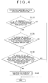
FIG. 4 is a flowchart that shows the procedure of "estimated induced voltage calculation routine" that is executed by an electronic control unit according to the embodiment. - An embodiment of the invention will be described with reference to
FIG. 1 to FIG. 4 . An electricpower steering system 1 includes a steering angle transmission mechanism (steering system) 10, anEPS actuator 20, and anelectronic control unit 30. The steering angle transmission mechanism (steering system) 10 transmits rotation of asteering wheel 2 to steeredwheels 3. TheEPS actuator 20 applies force for assisting an operation of the steering wheel 2 (hereinafter, referred to as "assist force") to the steeringangle transmission mechanism 10. Theelectronic control unit 30 controls theEPS actuator 20. Further, the electricpower steering system 1 is provided with a plurality of sensors that detect the operating states of these devices. - The steering
angle transmission mechanism 10 includes a steering shaft 11, a rack andpinion mechanism 12, arack shaft 13, andtie rods 14. The steering shaft 11 rotates in response to an operation of thesteering wheel 2. The rack andpinion mechanism 12 transmits rotation of the steering shaft 11 to therack shaft 13. Therack shaft 13 operates thetie rods 14. Thetie rods 14 respectively operate knuckles. - The
EPS actuator 20 includes amotor 21 and areduction mechanism 22. Themotor 21 applies torque to the steering shaft 11. Thereduction mechanism 22 reduces the speed of rotation of themotor 21. A brushed motor is employed as themotor 21. The rotation of themotor 21 is reduced in speed by thereduction mechanism 22 and is then transmitted to the steering shaft 11. At this time, torque applied from themotor 21 to the steering shaft 11 acts as assist force. - The steering
angle transmission mechanism 10 operates as follows. That is, when thesteering wheel 2 is operated, assist force is applied to the steering shaft 11, and the steering shaft 11 rotates. The rotation of the steering shaft 11 is converted to a linear motion of therack shaft 13 by the rack andpinion mechanism 12. The linear motion of therack shaft 13 is transmitted to the knuckles via thetie rods 14 that are coupled to respective ends of therack shaft 13. Then, the steered angle of the steeredwheels 3 is changed with the movement of the knuckles. - A steering angle θs of the
steering wheel 2 is determined using the neutral position of thesteering wheel 2 as a reference position. That is, where the steering angle θs of thesteering wheel 2 that is placed at the neutral position is "0", when thesteering wheel 2 is rotated clockwise or counterclockwise from the neutral position, the steering angle θs increases with an increase in a rotation angle with respect to the neutral position. - The steering state of the
steering wheel 2 is classified into "rotating state", "neutral state" and "retained state". The "rotating state" indicates the state where thesteering wheel 2 is rotating. The "neutral state" indicates the state where thesteering wheel 2 is placed at the neutral position. The "retained state" indicates the state where thesteering wheel 2 is kept at a position that the steering wheel has reached after being rotated clockwise or counterclockwise from the neutral position. In addition, the "rotating state" is further classified into "turning state" and "returning state". The "turning state" indicates the state where the steering angle θs is being increased. The "returning state" indicates the state where the steering angle θs is being reduced. - The electric
power steering system 1 includes atorque sensor 31, avehicle speed sensor 32, and a steering sensor 33 (rotation angular velocity acquisition unit). Thetorque sensor 31 detects torque of thesteering wheel 2. Thevehicle speed sensor 32 detects a value corresponding to a vehicle speed. Thesteering sensor 33 detects the steering angle θs of thesteering wheel 2. These sensors output signals corresponding to changes in the states of the respective detection targets as follows. - The
torque sensor 31 outputs a signal (hereinafter, referred to as "output signal SA"), corresponding to a magnitude of torque applied to the steering shaft 11 through an operation of thesteering wheel 2, to theelectronic control unit 30. Thevehicle speed sensor 32 outputs a signal (hereinafter, referred to as "output signal SB"), corresponding to a rotation speed of the steeredwheels 3, to theelectronic control unit 30. Thesteering sensor 33 outputs a signal (hereinafter, referred to as "output signal SC"), corresponding to a rotation amount of thesteering wheel 2, to theelectronic control unit 30. - The
electronic control unit 30 executes the following calculations on the basis of the signals output from the sensors. Theelectronic control unit 30 calculates a value corresponding to the magnitude of torque input into the steering shaft 11 (hereinafter, referred to as "steering torque τ") through the operation of thesteering wheel 2, on the basis of the output signal SA from thetorque sensor 31. In addition, theelectronic control unit 30 calculates a value corresponding to a traveling speed of the vehicle (hereinafter, referred to as "vehicle speed V") on the basis of the output signal SB from thevehicle speed sensor 32. In addition, theelectronic control unit 30 calculates the steering angle θs of thesteering wheel 2 on the basis of the output signal SC from thesteering sensor 33. - In addition, the
electronic control unit 30 executes the following motor control. Theelectronic control unit 30 executes power assist control and steering torque shift control. In the power assist control, a motor output for applying assist force to the steering system is adjusted. In the steering torque shift control, the motor output is corrected to adjust a steering feel felt by a driver who operates thesteering wheel 2. - In the steering torque shift control, the steering torque τ is corrected on the basis of the steering state of the
steering wheel 2 to improve steering feel. Then, the corrected value is output as a corrected torque τa. In the power assist control, a current command value Ia for driving themotor 21 is calculated on the basis of the vehicle speed V and the corrected torque τa. - The configuration of the
electronic control unit 30 will be described with reference toFIG. 2 . Theelectronic control unit 30 includes amotor control unit 40 and a drivingcircuit 50. Themotor control unit 40 generates a signal corresponding to driving electric power that is supplied to the motor 21 (hereinafter, referred to as "motor control signal Sm"). The drivingcircuit 50 supplies themotor 21 with driving electric power corresponding to the motor control signal Sm. - The driving
circuit 50 is provided with a voltage sensor 51 and acurrent sensor 52. The voltage sensor 51 detects a voltage between terminals of the motor 21 (hereinafter, referred to as "motor voltage Vm"). Thecurrent sensor 52 detects a current supplied to the motor 21 (hereinafter, referred to as "motor current Im"). - The
motor control unit 40 includes a current commandvalue calculation unit 60, afeedback correction unit 70, a motor controlsignal output unit 80, and a rotation angularvelocity calculation unit 90. The current commandvalue calculation unit 60 calculates a value of current that is supplied to the motor 21 (hereinafter, referred to as "current command value Ia"). The motor controlsignal output unit 80 generates the motor control signal Sm. The rotation angularvelocity calculation unit 90 calculates the rotation angular velocity ωm of themotor 21 as an estimated rotation angular velocity ωma. - The
feedback correction unit 70 corrects the current command value Ia on the basis of the difference between the motor current Im of themotor 21 and the current command value Ia for themotor 21, and executes feedback control such that the motor current Im converges to the current command value Ia. The motor controlsignal output unit 80 generates the motor control signal Sm on the basis of a corrected current command value Ib output from thefeedback correction unit 70. - The current command
value calculation unit 60 includes a basicassist calculation unit 61 and a torqueshift calculation unit 62. The basicassist calculation unit 61 calculates a basic component of the current command value Ia (hereinafter, referred to as "basic control amount Ias"). The torqueshift calculation unit 62 corrects the steering torque τ on the basis of the vehicle speed V and the estimated rotation angular velocity ωma. - The torque
shift calculation unit 62 corrects the steering torque τ (steering torque shift control). Specifically, when thesteering wheel 2 is in the retained state or the returning state, the torqueshift calculation unit 62 corrects the steering torque τ to increase the steering torque τ. In addition, when thesteering wheel 2 is in the retained state or the returning state, the torqueshift calculation unit 62 increases an amount of increase in the steering torque τ as the vehicle speed V decreases, and increases an amount of increase in the steering torque τ as the absolute value of the estimated rotation angular velocity ωma increases. - On the other hand, when the
steering wheel 2 is in the turning state, the torqueshift calculation unit 62 sets the correction amount of the steering torque τ at "0". That is, the torqueshift calculation unit 62 makes an assist amount larger when thesteering wheel 2 is in the retained state or in the returning state than when thesteering wheel 2 is in the turning state. Thus, the steering feel improves. - In which of the turning state, the retained state and the returning state the
steering wheel 2 is determined by the following method. That is, when the sign of the steering torque τ coincides with the sign of the estimated rotation angular velocity ωma, it is determined that thesteering wheel 2 is in the turning state. When the sign of the steering torque τ does not coincide with the sign of the estimated rotation angular velocity ωma, it is determined that thesteering wheel 2 is in the returning state. When the absolute value of the estimated rotation angular velocity ωma is smaller than a predetermined value ω0, it is determined that thesteering wheel 2 is in the retained state. - The basic
assist calculation unit 61 calculates a basic control amount Ias on the basis of the corrected torque τa and the vehicle speed V. Specifically, the basicassist calculation unit 61 increases the basic control amount Ias as the vehicle speed V decreases. In addition, the basicassist calculation unit 61 increases the basic control amount Ias as the corrected torque τa increases. - The rotation angular
velocity calculation unit 90 calculates the estimated rotation angular velocity ωma according toEquation 1 indicated below, which serves as a motor equation. The estimated rotation angular velocity ωma is used in the torqueshift calculation unit 62. Note that the brushedmotor 21 is not provided with a sensor that detects the rotation angular velocity ωm of themotor 21, so the rotation angular velocity ωm of themotor 21 is calculated as the estimated rotation angular velocity ωma according toEquation 1 indicated below.
"Vm" denotes a motor voltage Vm (voltage between the terminals) received from the voltage sensor 51.
"Im" denotes a motor current Im received from thecurrent sensor 52.
"Rm" denotes a motor resistance Rm prestored in a storage unit. A preset fixed value is used as the motor resistance Rm.
"Ke" denotes a back electromotive force constant. - With the above-described configuration, the
motor control unit 40 operates as follows. That is, themotor control unit 40 calculates the estimated rotation angular velocity ωma using the rotation angularvelocity calculation unit 90. Then, themotor control unit 40 corrects the steering torque τ on the basis of the estimated rotation angular velocity ωma and the vehicle speed V, and calculates the corrected torque τa. Furthermore, themotor control unit 40 generates the basic control amount Ias on the basis of the corrected torque τa and the vehicle speed V. The basic control amount Ias is corrected on the basis of the motor current Im through feedback control to generate the corrected current command value Ib. Then, the motor control signal Sm is generated on the basis of the corrected current command value Ib obtained by correcting the basic control amount Ias. - As shown in
FIG. 2 , themotor control unit 40 includes a back electromotive forceconstant updating unit 100 that updates the back electromotive force constant Ke, in addition to the above-described calculation elements. The back electromotive forceconstant updating unit 100 includes a steering angularvelocity calculation unit 110, an inducedvoltage calculation unit 120, and a back electromotive forceconstant calculation unit 130. The steering angularvelocity calculation unit 110 calculates a steering angular velocity ωs on the basis of the steering angle θs. The inducedvoltage calculation unit 120 estimates the induced voltage E of themotor 21. The back electromotive forceconstant calculation unit 130 calculates the back electromotive force constant Ke of themotor 21. - The induced
voltage calculation unit 120 calculates an estimated induced voltage EX of themotor 21 according toEquation 2 andEquation 3, using a disturbance observer. The disturbance observer calculates the estimated induced voltage EX according to the following equations, for example.

"ξ" denotes an intermediate variable.
"G" denotes an observer gain (fixed value).
"EX" denotes an estimated induced voltage.
"L" denotes an inductance.
"/dt" denotes temporal differentiation. - The induced
voltage calculation unit 120 calculates the estimated induced voltage EX when the following first to third conditions are satisfied. Then, the calculated steering angular velocity ωs and estimated induced voltage EX are stored as a set of data. - First Condition: The absolute value of the steering angular velocity ωs is larger than a threshold HA.
- Second Condition: The absolute value of an amount of change (a rate of change) in the steering angular velocity ωs is smaller than a reference change amount HB.
- Third Condition: The absolute value of a difference between the steering angular velocity ωs when the estimated induced voltage EX is calculated in the present routine and the steering angular velocity ωs when the estimated induced voltage EX is calculated in the immediately preceding routine is smaller than a set value DS.
- The conditions (the first to third conditions) for calculating the estimated induced voltage EX will be described with reference to
FIG. 3A to FIG. 3C . The steering angular velocity ωs is periodically detected. The steering angular velocity ωs changes depending on the operating state of thesteering wheel 2. When thesteering wheel 2 is in the turning state, the steering angular velocity ωs increases in the positive direction. When thesteering wheel 2 is in the retained state, the steering angular velocity ωs takes a value close to 0. When thesteering wheel 2 is in the returning state, the steering angular velocity ωs increases in the negative direction. - For example, as shown in the graph of the steering angular velocity ωs in
FIG. 3A , when thesteering wheel 2 is turned, the magnitude of the steering angular velocity ωs changes with a change in a driver's steering operation. The graph shows a state where thesteering wheel 2 is rotated while the steering angular velocity ωs is changed in the same direction as a driver's steering operation direction. - At this time, as shown in the graph of the amount of change in the steering angular velocity ωs in
FIG. 3B , the amount of change (rate of change) in the steering angular velocity ωs increases in the positive direction when the steering angular velocity ωs increases, becomes a value substantially equal to 0 when the steering angular velocity ωs is constant, and increases in the negative direction when the steering angular velocity ωs decreases. - In such a change in the steering angular velocity ωs, the estimated induced voltage EX is calculated when the above-described first to third conditions are satisfied. That is, as shown in
FIG. 3A to FIG. 3C , the estimated induced voltage EX is calculated, when the absolute value of the steering angular velocity ωs is large, the amount of change in the steering angular velocity ωs is small, and the absolute value Dωs of the difference between the steering angular velocity ωs in the present routine and the steering angular velocity ωs when the estimated induced voltage EX is calculated in the immediately preceding routine is smaller than the set value DS. That is, when the steering angular velocity ωs is stable and the estimated induced voltage EX takes a relatively large value, the estimated induced voltage EX is calculated. - The procedure of a routine of calculating the estimated induced voltage EX will be described with reference to
FIG. 4 . Note that the routine is repeatedly executed by theelectronic control unit 30 at predetermined calculation intervals. In step S110, it is determined whether the absolute value of the steering angular velocity ωs is larger than the threshold HA. When the absolute value of the steering angular velocity ωs is smaller than or equal to the threshold HA, the present calculation routine ends. On the other hand, when the absolute value of the steering angular velocity ωs is larger than the threshold HA, the next step is executed. - In step S120, it is determined whether the absolute value of the amount of change (rate of change) in the steering angular velocity ωs is smaller than the reference change amount HB. When the amount of change (rate of change) in the steering angular velocity ωs is larger than or equal to the reference change amount HB, the present calculation routine ends. On the other hand, when the amount of change (rate of change) in the steering angular velocity ωs is smaller than the reference change amount HB, the next step is executed
- In
step S 130, it is determined whether the absolute value Dωs of the difference between a steering angular velocity ωs1 (a first steering angular velocity ωs1 that may be used as a first corresponding rotation angular velocity in the invention) when the estimated induced voltage EX is calculated in the immediately preceding calculation routine and a steering angular velocity ωs2 (a second steering angular velocity ωs2 that may be used as a second corresponding rotation angular velocity in the invention) in the present calculation routine is smaller than the set value DS. When a negative determination is made, the present calculation routine ends. On the other hand, when an affirmative determination is made, the estimated induced voltage EX is calculated in step S140. - Next, the back electromotive force
constant calculation unit 130 will be described. The back electromotive forceconstant calculation unit 130 calculates a new back electromotive force constant Ke according to Equation 4.
"EX1" denotes the first estimated induced voltage at the steering angular velocity ωs1. "EX2" denotes the second estimated induced voltage at the steering angular velocity ωs2. "Ke1" denotes a first back electromotive force constant at the steering angular velocity ωs1.
"Ke2" denotes a second back electromotive force constant at the steering angular velocity ωs2. That is, "Ke2" denotes a back electromotive force constant that is calculated in the present calculation routine.
The absolute value of the difference between the steering angular velocity ωs1 and the steering angular velocity ωs2 is smaller than the set value DS. - The manner of deriving Equation 4 will be described below. Generally, the relation among the induced voltage E of the
motor 21, the back electromotive force constant Ke and the rotation angular velocity ωm of themotor 21 is as follows.


The induced voltage E1, the first back electromotive force constant Ke1 and the rotation angular velocity ωm1 of themotor 21 respectively indicate the induced voltage E, the back electromotive force constant Ke and the rotation angular velocity ωm of themotor 21 at time t1. The induced voltage E2, the second back electromotive force constant Ke2 and the rotation angular velocity ωm2 of themotor 21 respectively indicate the induced voltage E, the back electromotive force constant Ke and the rotation angular velocity ωm of themotor 21 at time t2. - Note that, in the following description, the induced voltage E1 will be denoted by "E1", the induced voltage E2 will be denoted by "E2", the first back electromotive force constant Ke1 will be denoted by "Ke1", the second back electromotive force constant Ke2 will be denoted by "Ke2", the rotation angular velocity ωm1 of the
motor 21 will be denoted by "ωm1" and the rotation angular velocity ωm2 of themotor 21 will be denoted by "ωm2". - When ωm1 is equal to ωm2, Equation 6 is established.

That is, when the rotation angular velocity ωm1 of themotor 21, acquired at time t1, and the rotation angular velocity ωm2 of themotor 21, acquired at time t2, coincide with each other, the second back electromotive force constant Ke2 at time t2 is calculated on the basis of the first back electromotive force constant Ke1 at time t1 and the ratio of the induced voltage E2 at time t2 to the induced voltage E1 at time t1. - In the case of the brushed
motor 21, it is not possible to acquire an actual value of the rotation angular velocity ωm of themotor 21. In addition, generally, it is also not possible to acquire an actual value of the induced voltage E of themotor 21. Then, the parameters in Equation 6, that is, the rotation angular velocity ωm and induced voltage E of themotor 21 are replaced as follows. - Because the rotation angular velocity ωm of the
motor 21 is correlated with the steering angular velocity ωs, the steering angular velocity ωs is used instead of the rotation angular velocity ωm of themotor 21. In addition, instead of the induced voltage E, the estimated induced voltage EX calculated by the disturbance observer is used. It is possible to accurately calculate the estimated induced voltage EX with the use of the disturbance observer, so an error due to this replacement is small. - Equation 4 described above is derived in the above manner. The back electromotive force constant Ke that is newly calculated according to Equation 4 is stored as the newest back electromotive force constant Ke. Then, the newest back electromotive force constant Ke is used to calculate the estimated rotation angular velocity ωma of the
motor 21. - Update of the back electromotive force constant Ke will be described with reference to the graph of the back electromotive force constant Ke shown in
FIG. 3C . At time t1, the steering angular velocity ωs satisfies the first to third conditions. At this time, the first back electromotive force constant Ke1 is calculated. Then, the first back electromotive force constant Ke1 is stored as a new back electromotive force constant Ke. - At time t2, the steering angular velocity ωs satisfies the first to third conditions. At this time, the second estimated induced voltage EX2 is calculated. Then, the first estimated induced voltage EX1 when the steering angular velocity ωs satisfies the first to third conditions last time is used, and a new second back electromotive force constant Ke2 is calculated according to Equation 4. Then, the second back electromotive force constant Ke2 is stored as a new back electromotive force constant Ke.
- Next, the operation and advantageous effects of calculating a new back electromotive force constant Ke according to Equation 4 will be described. Conventionally, the motor equation indicated in
Equation 1 has been used to calculate the rotation angular velocity ωm of themotor 21, that is, themotor 21 that is not provided with a rotation angular velocity detecting device (resolver). Then, a fixed value has been used as the back electromotive force constant Ke. - However, it is found that it is necessary to correct the back electromotive force constant Ke to accurately obtain the rotation angular velocity ωm of the
motor 21. That is, it becomes apparent that the back electromotive force constant Ke changes depending on a temperature of themotor 21 and abrasion, or the like, of components of themotor 21. Further, it is found that a change in the back electromotive force constant Ke is non-negligible in accurately calculating the rotation angular velocity ωm. - Then, the back electromotive force constant Ke is calculated on the basis of an actual physical quantity of the
motor 21. Specifically, the back electromotive force constant Ke is calculated according to Equation 4. Then, this value is used to calculate the estimated rotation angular velocity ωma of themotor 21. Therefore, the estimated rotation angular velocity ωma is calculated on the basis of the back electromotive force constant Ke corresponding to the state of themotor 21. As a result, the accuracy increases. That is, the absolute value of the difference between the estimated rotation angular velocity ωma and the actual rotation angular velocity ωm reduces. Thus, the control accuracy of steering torque shift control based on the estimated rotation angular velocity ωma increases. As a result, the steering feel improves. - Furthermore, the estimated induced voltage EX used to calculate the back electromotive force constant Ke is calculated when the first to third conditions are satisfied, as described above. That is, according to the first condition, when the absolute value of the steering angular velocity ωs is larger than the threshold HA, that is, when an error included in the estimated induced voltage EX is small, the back electromotive force constant Ke is calculated. Therefore, the accuracy of the back electromotive force constant Ke increases.
- In addition, according to the second condition, when the absolute value of the amount of change (the rate of change) in the steering angular velocity ωs is smaller than the reference change amount HB, the estimated induced voltage EX is calculated. Therefore, variations of the estimated induced voltage EX against the steering angular velocity ωs are reduced. Because the back electromotive force constant Ke is calculated on the basis of the estimated induced voltage EX, the accuracy of the back electromotive force constant Ke increases.
- That is, in comparison with the case where the estimated induced voltage EX is calculated without requiring satisfaction of the first and second conditions, the accuracy of the estimated induced voltage EX improves. Therefore, the back electromotive force constant Ke is calculated further accurately.
- According to the third condition, the following advantageous effects are obtained. According to the third condition, the estimated induced voltage EX is calculated when the
motor 21 is in substantially the same motion condition, that is, when the steering angular velocity ωs1 at the time when the estimated induced voltage EX is calculated in the immediately preceding routine is close to the steering angular velocity ωs2 at the time when the estimated induced voltage EX is calculated in the present routine (the absolute value of the difference between ωs1 and ωs2 is smaller than the set value DS). Then, as shown in Equation 4, the back electromotive force constant Ke is calculated on the basis of the ratio between the two estimated induced voltages EX when themotor 21 is in substantially the same motion condition. - When the back electromotive force constant Ke is calculated on the basis of the ratio between the two estimated induced voltages EX calculated when the
motor 21 is in different motion conditions, it is necessary to take into account contribution of parameters, other than the estimated induced voltage EX, to the back electromotive force constant Ke. However, according to the third condition, it is almost unnecessary to take into account contribution of such parameters, other than the estimated induced voltage EX. Therefore, it is possible to further accurately calculate the back electromotive force constant Ke. - An alternative embodiment of a method of calculating the back electromotive force constant Ke will be described. In the above-described embodiment, a new back electromotive force constant Ke is calculated according to Equation 4.
- In the case where Equation 4 is used, when the absolute value of the difference between the steering angular velocity ωs1 and the steering angular velocity ωs2 is smaller than the set value DS, the back electromotive force constant Ke is calculated using the first estimated induced voltage EX1 and the second estimated induced voltage EX2 that correspond to the steering angular velocity ωs1 and the steering angular velocity ωs2, respectively. That is, when the absolute value of the difference between the steering angular velocity ωs1 and the steering angular velocity ωs2 is smaller than the set value DS, the back electromotive force constant Ke is updated.
- In contrast to this, in the alternative embodiment, the back electromotive force constant Ke is calculated without requiring satisfaction of the condition that the absolute value of the difference between the steering angular velocity ωs1 and the steering angular velocity ωs2 is smaller than the set value DS. Generally, Equation 5, that is, Equation 51 and
Equation 52, are satisfied. Here, the left-hand side ofEquation 52 is divided by the left-hand side of Equation 51, and the right-hand side of Equation 51 is divided by the right-hand side ofEquation 2. Thus, Equation 7 is established.
Then, as in the case described above, instead of the "induced voltage E", the "estimated induced voltage EX" is used. In addition, the rotation angular velocity ωm of themotor 21 is correlated with the steering angular velocity ωs. Therefore, "ωs1/ωs2" is used instead of "ωm1/ωm2". - In this way, Equation 8 is established.

That is, a new second back electromotive force constant Ke2 is calculated on the basis of the steering angular velocity ωs1, the steering angular velocity ωs2, the first estimated induced voltage EX1 at the steering angular velocity ωs1, the second estimated induced voltage EX2 at the steering angular velocity ωs2, and the first back electromotive forceconstant Ke 1 calculated last time. - Note that, even when the back electromotive force constant Ke is calculated according to Equation 8, it is considered that the absolute value of the difference between the steering angular velocity ωs1 and the steering angular velocity ωs2 is desirably smaller than a predetermined set value DSa. This is because, when the absolute value of the difference between the steering angular velocity ωs1 and the steering angular velocity ωs2 is large, the
motor 21 is in the different motion conditions and, therefore, it is considered that contribution of parameters, other than the estimated induced voltage EX and the steering angular velocity ωs, to the back electromotive force constant Ke exerts an influence. - According to the present embodiment, the following operation and advantageous effects are obtained. (1) In the present embodiment, the back electromotive force constant Ke is calculated on the basis of the steering angular velocity ωs and the estimated induced voltage EX.
- The back electromotive force constant Ke is a value based on the induced voltage EX and the rotation angular velocity ωm of the
motor 21. Therefore, the back electromotive force constant Ke is calculated on the basis of the steering angular velocity ωs, corresponding to the rotation angular velocity ωm of themotor 21, and the estimated induced voltage EX. - That is, the back electromotive force constant Ke is not set at a fixed value, and the back electromotive force constant Ke is calculated using the parameters based on the
actual motor 21. Therefore, it is possible to reduce the absolute value of the difference between the actual back electromotive force constant Ke and the back electromotive force constant Ke used to calculate the estimated rotation angular velocity ωma. - Because the estimated rotation angular velocity ωma is calculated on the basis of the thus obtained back electromotive force constant Ke, it is possible to reduce the frequency at which the absolute value of the difference between the estimated rotation angular velocity ωma and the actual rotation angular velocity ωm is large. As a result, it is possible to improve the control accuracy of various controls that are executed on the basis of the estimated rotation angular velocity ωma.
- (2) In the present embodiment, the second back electromotive force constant Ke2 is calculated on the basis of the first back electromotive force constant Ke1 and the ratio of the second estimated induced voltage EX2 to the first estimated induced voltage EX1. With this configuration, a new back electromotive force constant Ke is calculated in association with the degree of change in the estimated induced voltage EX. That is, the degree of change in the estimated induced voltage EX under a predetermined condition is reflected in the back electromotive force constant Ke. Therefore, it is possible to suppress an increase in the absolute value of the difference between the actual back electromotive force constant Ke and the back electromotive force constant Ke used to calculate the estimated rotation angular velocity ωma.
- (3) In the present embodiment, as shown in
FIG. 3A to FIG. 4 , the estimated induced voltage EX is calculated when the absolute value of the steering angular velocity ωs is larger than the threshold HA. When the rotation angular velocity ωm of themotor 21 is reduced, the induced voltage (estimated induced voltage EX) is also reduced. Note that, there is a deviation between the estimated induced voltage EX and the actual induced voltage E of themotor 21. - When the estimated induced voltage EX is low, an error included in the absolute value of the estimated induced voltage EX is large. Therefore, when the back electromotive force constant Ke is calculated on the basis of the estimated induced voltage EX, the accuracy of the back electromotive force constant Ke is low as compared with the case where the back electromotive force constant Ke is calculated when the absolute value of the estimated induced voltage EX is large.
- However, with the above-described configuration, the back electromotive force constant Ke is calculated on the basis of the estimated induced voltage EX when the absolute value of the steering angular velocity ωs is larger than the threshold HA, that is, when the induced voltage (estimated induced voltage EX) is high. Thus, it is possible to further improve the accuracy of the back electromotive force constant Ke.
- (4) In the present embodiment, the estimated induced voltage EX is calculated when the condition that the absolute value of the amount of change in the steering angular velocity ωs is smaller than the reference change amount HB is satisfied in addition to the requirement in the above description (3). The reason of this is as follows.
- Even when the estimated induced voltage EX is calculated at a predetermined steering angular velocity ωs, the estimated induced voltage EX calculated when the amount of change in the steering angular velocity ωs is large may be different from the estimated induced voltage EX calculated when the absolute value of the amount of change in the steering angular velocity ωs is small.
- This is because there is a time lag between the time at which the estimated induced voltage EX is calculated and the time at which it is determined that the steering angular velocity ωs is the predetermined value. That is, if the absolute value of the amount of change in the steering angular velocity ωs is not limited as the condition for calculating the estimated induced voltage EX, the estimated induced voltage EX may vary.
- However, with the above configuration, the condition that the absolute value of the amount of change in the steering angular velocity ωs is smaller than the reference change amount HB is used as the condition for calculating the estimated induced voltage EX. Therefore, it is possible to suppress variations in estimated induced voltage EX at the time of calculating the estimated induced voltage EX. Thus, it is possible to improve the accuracy of the back electromotive force constant Ke.
- (5) In the present embodiment, the estimated induced voltage EX is calculated when the condition that the absolute value of the difference between the previous steering angular velocity ωs1 (first steering angular velocity) and the current steering angular velocity ωs2 (second steering angular velocity) is smaller than the set value DS is satisfied in addition to the requirement in the above description (4).
- When there is a difference between the steering angular velocity ωs1 in the immediately preceding routine and the steering angular velocity ωs2 in the present routine, as described in the alternative embodiment, a new back electromotive force constant Ke is calculated on the basis of the ratio of the steering angular velocity ωs1 in the immediately preceding routine to the steering angular velocity ωs2 in the present routine and the ratio of the second estimated induced voltage EX2 to the first estimated induced voltage EX1.
- On the other hand, in the above configuration, the condition that the absolute value of the difference between the steering angular velocity ωs1 in the immediately preceding routine and the steering angular velocity ωs2 in the present routine is smaller than the set value DS is set as the condition for calculating the estimated induced voltage EX. Therefore, it is possible to easily calculate the back electromotive force constant Ke.
- (6) In the present embodiment, in order to calculate the back electromotive force constant Ke according to Equation 5, the actual rotation angular velocity ωm of the
motor 21 is required as a parameter. However, in the above configuration, the steering angular velocity ωs is used as a corresponding rotation angular velocity in place of the rotation angular velocity ωm of themotor 21. - The steering angular velocity ωs is correlated with the rotation angular velocity ωm of the
motor 21. It is considered that, instead of the steering angular velocity ωs, for example, the steered velocity of the steeredwheels 3 may be used. However, when the number of mechanical elements interposed between themotor 21 and the steeredwheels 3 is larger than the number of mechanical elements interposed between themotor 21 and thesteering wheel 2, the correlation between the steered velocity of the steeredwheels 3 and the rotation angular velocity ωm of themotor 21 is low. That is, the correlation between the steering angular velocity ωs and the rotation angular velocity ωm of themotor 21 is higher than the correlation between the steered velocity of a steering system component, which is located further away from themotor 21 than the mechanical elements between themotor 21 and the steeredwheels 3, and the rotation angular velocity ωm of themotor 21. - Therefore, with the above configuration, it is possible to accurately calculate the back electromotive force constant Ke in comparison with the case where the steered velocity of the steering system component located further away from the
motor 21 is used as the corresponding rotation angular velocity. - Note that the invention is not limited to the above-described embodiments, and may be implemented, for example, in the following alternative embodiments. In addition, the following alternative embodiments are not only applied to the above-described embodiments, and may be implemented in combination.
- In the above-described embodiments, the motor resistance Rm is a fixed value. However, because there is a correlation between the motor resistance Rm and the motor current Im, the motor resistance Rm may be corrected on the basis of the motor current Im. Specifically, a map that indicates the correlation between the motor resistance Rm and the motor current Im is set in advance, and the motor resistance Rm is corrected on the basis of the map. With this configuration, it is possible to further accurately calculate the rotation angular velocity ωm of the
motor 21. - In the above-described embodiments, the above-described disturbance observer is used to calculate the estimated induced voltage EX. However, the disturbance observer is not limited to the configuration based on
Equation 2 andEquation 3. That is, as long as a disturbance observer is derived by modeling a motor equation with the estimated induced voltage EX regarded as a turbulence element, the disturbance observer may be employed as a method of calculating the estimated induced voltage EX. - In the above-described embodiment, the first to third conditions for calculating the estimated induced voltage EX are provided. Then, it is determined whether the first to third conditions are satisfied using the steering angular velocity ωs as a parameter.
- The parameter used to determine whether the first to third conditions are satisfied may be a physical quantity other than the steering angular velocity ωs. That is, a parameter in the condition for calculating the estimated induced voltage EX may be the a parameter that is correlated with the rotation angular velocity ωm of the
motor 21. - For example, instead of the steering angular velocity ωs, the displacement (the amount of motion) of the
rack shaft 13 may be used. The displacement of therack shaft 13 is correlated with the rotation angular velocity ωm of themotor 21. Therefore, even when the displacement of therack shaft 13 is used as a parameter, it is possible to obtain the estimated induced voltage EX required to accurately calculate the back electromotive force constant Ke. In addition, other than the displacement of therack shaft 13, for example, a gear rotation speed of thereduction mechanism 22 or the estimated rotation angular velocity ωma may be used. - In the above-described embodiments, Equation 4 and Equation 8 are described as the equations for calculating the back electromotive force constant Ke. However, these equations may be corrected with a predetermined coefficient so that the calculated back electromotive force constant Ke is approximated to the actual back electromotive force constant Ke.
- In the above-described embodiments, the invention is applied to the electric
power steering system 1 that includes the brushed motor as themotor 21 of theEPS actuator 20. Alternatively, the invention may be applied to the electricpower steering system 1 that includes a brushless motor as themotor 21 of theEPS actuator 20. - In the above-described embodiment, the invention is applied to the column-type electric
power steering system 1. Alternatively, the invention may be applied to a pinion-type electric power steering system or a rack assist-type electric power steering system. In this case as well, configurations similar to the above embodiments are employed. Thus, advantageous effects similar to the advantageous effects of the above embodiments may be obtained. - According to the invention, it is possible to provide the electric power steering system that is able to accurately control the motor on the basis of the rotation angular velocity of the motor.
Claims (6)
- An electric power steering system that includes a motor that applies assist force to a steering system, comprising:a rotation angular velocity acquisition unit (33) that acquires a corresponding rotation angular velocity that corresponds to a rotation angular velocity of the motor (21);an induced voltage calculation unit (120) that calculates an induced voltage of the motor (21) as an estimated induced voltage at the same time that the corresponding rotation angular velocity is acquired;a back electromotive force constant calculation unit (130) that calculates a back electromotive force constant based on the corresponding rotation angular velocity and the estimated induced voltage; anda rotation angular velocity calculation unit (90) that calculates a rotation angular velocity of the motor (21) as an estimated rotation angular velocity based on a current of the motor (21), a voltage of the motor (21), the back electromotive force constant and a resistance of the motor (21).
- The electric power steering system according to claim 1, wherein
the corresponding rotation angular velocity acquired by the rotation angular velocity acquisition unit (33) is set as a first corresponding rotation angular velocity,
the corresponding rotation angular velocity acquired after acquisition of the first corresponding rotation angular velocity is set as a second corresponding rotation angular velocity,
the estimated induced voltage that corresponds to the first corresponding rotation angular velocity is set as a first estimated induced voltage,
the estimated induced voltage that corresponds to the second corresponding rotation angular velocity is set as a second estimated induced voltage,
the back electromotive force constant that corresponds to the first estimated induced voltage is set as a first back electromotive force constant,
the back electromotive force constant that corresponds to the second estimated induced voltage is set as a second back electromotive force constant, and
the back electromotive force constant calculation unit (130) calculates the second back electromotive force constant based on the first back electromotive force constant and a ratio of the second estimated induced voltage to the first estimated induced voltage. - The electric power steering system according to claim 1 or 2, wherein
when a magnitude of the corresponding rotation angular velocity is higher than a threshold, the estimated induced voltage is calculated. - The electric power steering system according to claim 1 or 2, wherein
when a magnitude of the corresponding rotation angular velocity is higher than a threshold and an amount of change in the corresponding rotation angular velocity is smaller than a reference change amount, the estimated induced voltage is calculated. - The electric power steering system according to claim 2, wherein
when a magnitude of the corresponding rotation angular velocity is higher than a threshold, an amount of change in the corresponding rotation angular velocity is smaller than a reference change amount and an absolute value of a difference between the first corresponding rotation angular velocity and the second corresponding rotation angular velocity is smaller than a set value, the estimated induced voltage is calculated. - The electric power steering system according to any one of claims 1 to 5,
wherein
the corresponding rotation angular velocity is a steering angular velocity of a steering wheel (2) or a displacement of a rack shaft (13).
Applications Claiming Priority (1)
| Application Number | Priority Date | Filing Date | Title |
|---|---|---|---|
| JP2011116949A JP5703963B2 (en) | 2011-05-25 | 2011-05-25 | Electric power steering device |
Publications (3)
| Publication Number | Publication Date |
|---|---|
| EP2527229A2 true EP2527229A2 (en) | 2012-11-28 |
| EP2527229A3 EP2527229A3 (en) | 2013-04-03 |
| EP2527229B1 EP2527229B1 (en) | 2014-09-10 |
Family
ID=46229197
Family Applications (1)
| Application Number | Title | Priority Date | Filing Date |
|---|---|---|---|
| EP12169085.3A Not-in-force EP2527229B1 (en) | 2011-05-25 | 2012-05-23 | Electric power steering system |
Country Status (4)
| Country | Link |
|---|---|
| US (1) | US8823305B2 (en) |
| EP (1) | EP2527229B1 (en) |
| JP (1) | JP5703963B2 (en) |
| CN (1) | CN102795261B (en) |
Cited By (1)
| Publication number | Priority date | Publication date | Assignee | Title |
|---|---|---|---|---|
| CN114039513A (en) * | 2021-11-11 | 2022-02-11 | 江苏科技大学 | Method and system for judging forward wind and backward wind of fan |
Families Citing this family (10)
| Publication number | Priority date | Publication date | Assignee | Title |
|---|---|---|---|---|
| JP5941871B2 (en) * | 2013-05-28 | 2016-06-29 | 本田技研工業株式会社 | Electric power steering device |
| JP6380014B2 (en) * | 2014-11-04 | 2018-08-29 | 株式会社ジェイテクト | Electric power steering device |
| KR101664039B1 (en) * | 2014-11-17 | 2016-10-10 | 현대자동차 주식회사 | System for estimating temperature of motor and method thereof |
| JP6355167B2 (en) * | 2015-09-28 | 2018-07-11 | トヨタ自動車株式会社 | Vehicle driving support control device |
| CN105450105B (en) * | 2015-12-16 | 2018-09-04 | 四川长虹电器股份有限公司 | A kind of back electromotive force constant detection method and air-conditioning equipment |
| CN106990356B (en) * | 2016-01-21 | 2023-04-28 | 珠海格力节能环保制冷技术研究中心有限公司 | Measuring device and measuring method for counter potential coefficient of linear motor |
| JP6714775B2 (en) * | 2017-05-08 | 2020-06-24 | アルプスアルパイン株式会社 | Motor with rotation angle detector, rotation angle detector for motor, and method for detecting rotation angle of motor with commutator |
| WO2019087454A1 (en) * | 2017-10-31 | 2019-05-09 | 株式会社アルバック | Vacuum pump and control method for same |
| JP6922669B2 (en) * | 2017-11-07 | 2021-08-18 | 株式会社ジェイテクト | Steering control device |
| JP6911714B2 (en) * | 2017-11-07 | 2021-07-28 | 株式会社ジェイテクト | Steering control device |
Citations (1)
| Publication number | Priority date | Publication date | Assignee | Title |
|---|---|---|---|---|
| JP2004066999A (en) | 2002-08-07 | 2004-03-04 | Honda Motor Co Ltd | Electric power steering device |
Family Cites Families (12)
| Publication number | Priority date | Publication date | Assignee | Title |
|---|---|---|---|---|
| JP4273775B2 (en) * | 2003-01-28 | 2009-06-03 | 株式会社安川電機 | Magnetic pole position estimation method and control device for permanent magnet type synchronous motor |
| JP2005083316A (en) * | 2003-09-10 | 2005-03-31 | Boc Edwards Kk | Motor control system and vacuum pump mounting the same |
| JP4613513B2 (en) * | 2004-04-28 | 2011-01-19 | 日本精工株式会社 | Electric power steering device |
| US8091679B2 (en) * | 2004-04-28 | 2012-01-10 | Nsk Ltd. | Electric power steering device |
| US7288911B2 (en) * | 2005-09-29 | 2007-10-30 | Agile Systems Inc. | System and method for commutating a motor |
| US8080957B2 (en) * | 2006-04-11 | 2011-12-20 | Nsk, Ltd. | Motor control device and motor-driven power steering system using the same |
| EP2026458A1 (en) * | 2006-05-31 | 2009-02-18 | NSK Ltd. | Electric power steering device |
| CN101911467B (en) * | 2008-01-16 | 2014-07-02 | 株式会社捷太格特 | Motor control device and electric power steering device |
| JP5172418B2 (en) * | 2008-03-28 | 2013-03-27 | 本田技研工業株式会社 | Control device for electric motor system |
| JP4609515B2 (en) * | 2008-04-02 | 2011-01-12 | トヨタ自動車株式会社 | Vehicle steering control device |
| JP5509677B2 (en) * | 2008-09-24 | 2014-06-04 | セイコーエプソン株式会社 | Device, method, motor, motor-mounted device, and computer program for calculating characteristics of motor |
| JP2011087402A (en) * | 2009-10-15 | 2011-04-28 | Jtekt Corp | Motor controller and electric power steering device |
-
2011
- 2011-05-25 JP JP2011116949A patent/JP5703963B2/en not_active Expired - Fee Related
-
2012
- 2012-05-21 US US13/476,398 patent/US8823305B2/en not_active Expired - Fee Related
- 2012-05-23 EP EP12169085.3A patent/EP2527229B1/en not_active Not-in-force
- 2012-05-25 CN CN201210168041.2A patent/CN102795261B/en not_active Expired - Fee Related
Patent Citations (1)
| Publication number | Priority date | Publication date | Assignee | Title |
|---|---|---|---|---|
| JP2004066999A (en) | 2002-08-07 | 2004-03-04 | Honda Motor Co Ltd | Electric power steering device |
Cited By (2)
| Publication number | Priority date | Publication date | Assignee | Title |
|---|---|---|---|---|
| CN114039513A (en) * | 2021-11-11 | 2022-02-11 | 江苏科技大学 | Method and system for judging forward wind and backward wind of fan |
| CN114039513B (en) * | 2021-11-11 | 2023-12-19 | 江苏科技大学 | Judgment method and judgment system for forward and reverse wind of fan |
Also Published As
| Publication number | Publication date |
|---|---|
| CN102795261A (en) | 2012-11-28 |
| CN102795261B (en) | 2016-07-06 |
| EP2527229A3 (en) | 2013-04-03 |
| JP2012245822A (en) | 2012-12-13 |
| JP5703963B2 (en) | 2015-04-22 |
| US20120299517A1 (en) | 2012-11-29 |
| EP2527229B1 (en) | 2014-09-10 |
| US8823305B2 (en) | 2014-09-02 |
Similar Documents
| Publication | Publication Date | Title |
|---|---|---|
| EP2527229B1 (en) | Electric power steering system | |
| CN111278715B (en) | Steering control device | |
| EP2900542B1 (en) | Steering control system for vehicle and steering control method for vehicle | |
| JP6769047B2 (en) | Steering control device | |
| EP2272735B1 (en) | Electric power steering system | |
| US9610973B2 (en) | Motor-driven power steering apparatus | |
| EP2915722A1 (en) | Electric power steering device | |
| CN110182253B (en) | Quadrant-type friction compensation for tire load estimation for steering systems | |
| JP5708572B2 (en) | Electric power steering device for vehicle | |
| JP2007261548A (en) | Electric power steering device | |
| JP2017077830A (en) | Electric power steering device | |
| JP2016107711A (en) | Control device | |
| US8838340B2 (en) | Electric power steering system | |
| EP3216675B1 (en) | Steering control system | |
| JP5817418B2 (en) | Electric power steering device | |
| JP6387657B2 (en) | Electric power steering control device | |
| JP2009029285A (en) | Vehicular steering device | |
| JP4487988B2 (en) | Electric power steering device | |
| CN110001764B (en) | High bandwidth universal electric power steering system controller | |
| US8560177B2 (en) | Electric power steering system | |
| EP2639137B1 (en) | Vehicle steering control system | |
| JP2017043114A (en) | Electric power steering device | |
| JP2012236531A (en) | Electric power steering device | |
| JP2013001241A (en) | Electric power steering device | |
| JP2006282173A (en) | Electric power steering device |
Legal Events
| Date | Code | Title | Description |
|---|---|---|---|
| PUAI | Public reference made under article 153(3) epc to a published international application that has entered the european phase |
Free format text: ORIGINAL CODE: 0009012 |
|
| AK | Designated contracting states |
Kind code of ref document: A2 Designated state(s): AL AT BE BG CH CY CZ DE DK EE ES FI FR GB GR HR HU IE IS IT LI LT LU LV MC MK MT NL NO PL PT RO RS SE SI SK SM TR |
|
| AX | Request for extension of the european patent |
Extension state: BA ME |
|
| RIN1 | Information on inventor provided before grant (corrected) |
Inventor name: KARIATSUMARI, YUJI Inventor name: NIIMI, KOZO |
|
| PUAL | Search report despatched |
Free format text: ORIGINAL CODE: 0009013 |
|
| AK | Designated contracting states |
Kind code of ref document: A3 Designated state(s): AL AT BE BG CH CY CZ DE DK EE ES FI FR GB GR HR HU IE IS IT LI LT LU LV MC MK MT NL NO PL PT RO RS SE SI SK SM TR |
|
| AX | Request for extension of the european patent |
Extension state: BA ME |
|
| RIC1 | Information provided on ipc code assigned before grant |
Ipc: B62D 5/04 20060101AFI20130227BHEP |
|
| 17P | Request for examination filed |
Effective date: 20131002 |
|
| RBV | Designated contracting states (corrected) |
Designated state(s): AL AT BE BG CH CY CZ DE DK EE ES FI FR GB GR HR HU IE IS IT LI LT LU LV MC MK MT NL NO PL PT RO RS SE SI SK SM TR |
|
| GRAP | Despatch of communication of intention to grant a patent |
Free format text: ORIGINAL CODE: EPIDOSNIGR1 |
|
| INTG | Intention to grant announced |
Effective date: 20140611 |
|
| GRAS | Grant fee paid |
Free format text: ORIGINAL CODE: EPIDOSNIGR3 |
|
| GRAA | (expected) grant |
Free format text: ORIGINAL CODE: 0009210 |
|
| AK | Designated contracting states |
Kind code of ref document: B1 Designated state(s): AL AT BE BG CH CY CZ DE DK EE ES FI FR GB GR HR HU IE IS IT LI LT LU LV MC MK MT NL NO PL PT RO RS SE SI SK SM TR |
|
| REG | Reference to a national code |
Ref country code: GB Ref legal event code: FG4D |
|
| REG | Reference to a national code |
Ref country code: CH Ref legal event code: EP |
|
| REG | Reference to a national code |
Ref country code: IE Ref legal event code: FG4D |
|
| REG | Reference to a national code |
Ref country code: AT Ref legal event code: REF Ref document number: 686532 Country of ref document: AT Kind code of ref document: T Effective date: 20141015 |
|
| REG | Reference to a national code |
Ref country code: DE Ref legal event code: R096 Ref document number: 602012003021 Country of ref document: DE Effective date: 20141023 |
|
| PG25 | Lapsed in a contracting state [announced via postgrant information from national office to epo] |
Ref country code: GR Free format text: LAPSE BECAUSE OF FAILURE TO SUBMIT A TRANSLATION OF THE DESCRIPTION OR TO PAY THE FEE WITHIN THE PRESCRIBED TIME-LIMIT Effective date: 20141211 Ref country code: ES Free format text: LAPSE BECAUSE OF FAILURE TO SUBMIT A TRANSLATION OF THE DESCRIPTION OR TO PAY THE FEE WITHIN THE PRESCRIBED TIME-LIMIT Effective date: 20140910 Ref country code: NO Free format text: LAPSE BECAUSE OF FAILURE TO SUBMIT A TRANSLATION OF THE DESCRIPTION OR TO PAY THE FEE WITHIN THE PRESCRIBED TIME-LIMIT Effective date: 20141210 Ref country code: FI Free format text: LAPSE BECAUSE OF FAILURE TO SUBMIT A TRANSLATION OF THE DESCRIPTION OR TO PAY THE FEE WITHIN THE PRESCRIBED TIME-LIMIT Effective date: 20140910 Ref country code: SE Free format text: LAPSE BECAUSE OF FAILURE TO SUBMIT A TRANSLATION OF THE DESCRIPTION OR TO PAY THE FEE WITHIN THE PRESCRIBED TIME-LIMIT Effective date: 20140910 Ref country code: LT Free format text: LAPSE BECAUSE OF FAILURE TO SUBMIT A TRANSLATION OF THE DESCRIPTION OR TO PAY THE FEE WITHIN THE PRESCRIBED TIME-LIMIT Effective date: 20140910 |
|
| REG | Reference to a national code |
Ref country code: NL Ref legal event code: VDEP Effective date: 20140910 |
|
| REG | Reference to a national code |
Ref country code: LT Ref legal event code: MG4D |
|
| PG25 | Lapsed in a contracting state [announced via postgrant information from national office to epo] |
Ref country code: HR Free format text: LAPSE BECAUSE OF FAILURE TO SUBMIT A TRANSLATION OF THE DESCRIPTION OR TO PAY THE FEE WITHIN THE PRESCRIBED TIME-LIMIT Effective date: 20140910 Ref country code: CY Free format text: LAPSE BECAUSE OF FAILURE TO SUBMIT A TRANSLATION OF THE DESCRIPTION OR TO PAY THE FEE WITHIN THE PRESCRIBED TIME-LIMIT Effective date: 20140910 Ref country code: RS Free format text: LAPSE BECAUSE OF FAILURE TO SUBMIT A TRANSLATION OF THE DESCRIPTION OR TO PAY THE FEE WITHIN THE PRESCRIBED TIME-LIMIT Effective date: 20140910 Ref country code: LV Free format text: LAPSE BECAUSE OF FAILURE TO SUBMIT A TRANSLATION OF THE DESCRIPTION OR TO PAY THE FEE WITHIN THE PRESCRIBED TIME-LIMIT Effective date: 20140910 |
|
| REG | Reference to a national code |
Ref country code: AT Ref legal event code: MK05 Ref document number: 686532 Country of ref document: AT Kind code of ref document: T Effective date: 20140910 |
|
| PG25 | Lapsed in a contracting state [announced via postgrant information from national office to epo] |
Ref country code: NL Free format text: LAPSE BECAUSE OF FAILURE TO SUBMIT A TRANSLATION OF THE DESCRIPTION OR TO PAY THE FEE WITHIN THE PRESCRIBED TIME-LIMIT Effective date: 20140910 |
|
| PG25 | Lapsed in a contracting state [announced via postgrant information from national office to epo] |
Ref country code: EE Free format text: LAPSE BECAUSE OF FAILURE TO SUBMIT A TRANSLATION OF THE DESCRIPTION OR TO PAY THE FEE WITHIN THE PRESCRIBED TIME-LIMIT Effective date: 20140910 Ref country code: CZ Free format text: LAPSE BECAUSE OF FAILURE TO SUBMIT A TRANSLATION OF THE DESCRIPTION OR TO PAY THE FEE WITHIN THE PRESCRIBED TIME-LIMIT Effective date: 20140910 Ref country code: SK Free format text: LAPSE BECAUSE OF FAILURE TO SUBMIT A TRANSLATION OF THE DESCRIPTION OR TO PAY THE FEE WITHIN THE PRESCRIBED TIME-LIMIT Effective date: 20140910 Ref country code: IS Free format text: LAPSE BECAUSE OF FAILURE TO SUBMIT A TRANSLATION OF THE DESCRIPTION OR TO PAY THE FEE WITHIN THE PRESCRIBED TIME-LIMIT Effective date: 20150110 Ref country code: RO Free format text: LAPSE BECAUSE OF FAILURE TO SUBMIT A TRANSLATION OF THE DESCRIPTION OR TO PAY THE FEE WITHIN THE PRESCRIBED TIME-LIMIT Effective date: 20140910 Ref country code: PT Free format text: LAPSE BECAUSE OF FAILURE TO SUBMIT A TRANSLATION OF THE DESCRIPTION OR TO PAY THE FEE WITHIN THE PRESCRIBED TIME-LIMIT Effective date: 20150112 |
|
| PG25 | Lapsed in a contracting state [announced via postgrant information from national office to epo] |
Ref country code: PL Free format text: LAPSE BECAUSE OF FAILURE TO SUBMIT A TRANSLATION OF THE DESCRIPTION OR TO PAY THE FEE WITHIN THE PRESCRIBED TIME-LIMIT Effective date: 20140910 Ref country code: AT Free format text: LAPSE BECAUSE OF FAILURE TO SUBMIT A TRANSLATION OF THE DESCRIPTION OR TO PAY THE FEE WITHIN THE PRESCRIBED TIME-LIMIT Effective date: 20140910 |
|
| REG | Reference to a national code |
Ref country code: DE Ref legal event code: R097 Ref document number: 602012003021 Country of ref document: DE |
|
| PLBE | No opposition filed within time limit |
Free format text: ORIGINAL CODE: 0009261 |
|
| STAA | Information on the status of an ep patent application or granted ep patent |
Free format text: STATUS: NO OPPOSITION FILED WITHIN TIME LIMIT |
|
| PG25 | Lapsed in a contracting state [announced via postgrant information from national office to epo] |
Ref country code: DK Free format text: LAPSE BECAUSE OF FAILURE TO SUBMIT A TRANSLATION OF THE DESCRIPTION OR TO PAY THE FEE WITHIN THE PRESCRIBED TIME-LIMIT Effective date: 20140910 |
|
| 26N | No opposition filed |
Effective date: 20150611 |
|
| PG25 | Lapsed in a contracting state [announced via postgrant information from national office to epo] |
Ref country code: IT Free format text: LAPSE BECAUSE OF FAILURE TO SUBMIT A TRANSLATION OF THE DESCRIPTION OR TO PAY THE FEE WITHIN THE PRESCRIBED TIME-LIMIT Effective date: 20140910 |
|
| PG25 | Lapsed in a contracting state [announced via postgrant information from national office to epo] |
Ref country code: SI Free format text: LAPSE BECAUSE OF FAILURE TO SUBMIT A TRANSLATION OF THE DESCRIPTION OR TO PAY THE FEE WITHIN THE PRESCRIBED TIME-LIMIT Effective date: 20140910 |
|
| REG | Reference to a national code |
Ref country code: CH Ref legal event code: PL |
|
| PG25 | Lapsed in a contracting state [announced via postgrant information from national office to epo] |
Ref country code: LU Free format text: LAPSE BECAUSE OF FAILURE TO SUBMIT A TRANSLATION OF THE DESCRIPTION OR TO PAY THE FEE WITHIN THE PRESCRIBED TIME-LIMIT Effective date: 20150523 Ref country code: LI Free format text: LAPSE BECAUSE OF NON-PAYMENT OF DUE FEES Effective date: 20150531 Ref country code: CH Free format text: LAPSE BECAUSE OF NON-PAYMENT OF DUE FEES Effective date: 20150531 Ref country code: MC Free format text: LAPSE BECAUSE OF FAILURE TO SUBMIT A TRANSLATION OF THE DESCRIPTION OR TO PAY THE FEE WITHIN THE PRESCRIBED TIME-LIMIT Effective date: 20140910 |
|
| REG | Reference to a national code |
Ref country code: IE Ref legal event code: MM4A |
|
| REG | Reference to a national code |
Ref country code: FR Ref legal event code: PLFP Year of fee payment: 5 |
|
| PG25 | Lapsed in a contracting state [announced via postgrant information from national office to epo] |
Ref country code: IE Free format text: LAPSE BECAUSE OF NON-PAYMENT OF DUE FEES Effective date: 20150523 |
|
| PG25 | Lapsed in a contracting state [announced via postgrant information from national office to epo] |
Ref country code: BE Free format text: LAPSE BECAUSE OF FAILURE TO SUBMIT A TRANSLATION OF THE DESCRIPTION OR TO PAY THE FEE WITHIN THE PRESCRIBED TIME-LIMIT Effective date: 20140910 |
|
| PG25 | Lapsed in a contracting state [announced via postgrant information from national office to epo] |
Ref country code: MT Free format text: LAPSE BECAUSE OF FAILURE TO SUBMIT A TRANSLATION OF THE DESCRIPTION OR TO PAY THE FEE WITHIN THE PRESCRIBED TIME-LIMIT Effective date: 20140910 |
|
| GBPC | Gb: european patent ceased through non-payment of renewal fee |
Effective date: 20160523 |
|
| REG | Reference to a national code |
Ref country code: FR Ref legal event code: PLFP Year of fee payment: 6 |
|
| PG25 | Lapsed in a contracting state [announced via postgrant information from national office to epo] |
Ref country code: BG Free format text: LAPSE BECAUSE OF FAILURE TO SUBMIT A TRANSLATION OF THE DESCRIPTION OR TO PAY THE FEE WITHIN THE PRESCRIBED TIME-LIMIT Effective date: 20140910 Ref country code: HU Free format text: LAPSE BECAUSE OF FAILURE TO SUBMIT A TRANSLATION OF THE DESCRIPTION OR TO PAY THE FEE WITHIN THE PRESCRIBED TIME-LIMIT; INVALID AB INITIO Effective date: 20120523 Ref country code: SM Free format text: LAPSE BECAUSE OF FAILURE TO SUBMIT A TRANSLATION OF THE DESCRIPTION OR TO PAY THE FEE WITHIN THE PRESCRIBED TIME-LIMIT Effective date: 20140910 Ref country code: GB Free format text: LAPSE BECAUSE OF NON-PAYMENT OF DUE FEES Effective date: 20160523 |
|
| PG25 | Lapsed in a contracting state [announced via postgrant information from national office to epo] |
Ref country code: TR Free format text: LAPSE BECAUSE OF FAILURE TO SUBMIT A TRANSLATION OF THE DESCRIPTION OR TO PAY THE FEE WITHIN THE PRESCRIBED TIME-LIMIT Effective date: 20140910 |
|
| REG | Reference to a national code |
Ref country code: FR Ref legal event code: PLFP Year of fee payment: 7 |
|
| PG25 | Lapsed in a contracting state [announced via postgrant information from national office to epo] |
Ref country code: MK Free format text: LAPSE BECAUSE OF FAILURE TO SUBMIT A TRANSLATION OF THE DESCRIPTION OR TO PAY THE FEE WITHIN THE PRESCRIBED TIME-LIMIT Effective date: 20140910 |
|
| PG25 | Lapsed in a contracting state [announced via postgrant information from national office to epo] |
Ref country code: AL Free format text: LAPSE BECAUSE OF FAILURE TO SUBMIT A TRANSLATION OF THE DESCRIPTION OR TO PAY THE FEE WITHIN THE PRESCRIBED TIME-LIMIT Effective date: 20140910 |
|
| PGFP | Annual fee paid to national office [announced via postgrant information from national office to epo] |
Ref country code: DE Payment date: 20200512 Year of fee payment: 9 Ref country code: FR Payment date: 20200414 Year of fee payment: 9 |
|
| REG | Reference to a national code |
Ref country code: DE Ref legal event code: R119 Ref document number: 602012003021 Country of ref document: DE |
|
| PG25 | Lapsed in a contracting state [announced via postgrant information from national office to epo] |
Ref country code: DE Free format text: LAPSE BECAUSE OF NON-PAYMENT OF DUE FEES Effective date: 20211201 |
|
| PG25 | Lapsed in a contracting state [announced via postgrant information from national office to epo] |
Ref country code: FR Free format text: LAPSE BECAUSE OF NON-PAYMENT OF DUE FEES Effective date: 20210531 |