EP2527211A1 - Piston mechanism for a vehicle safety system - Google Patents
Piston mechanism for a vehicle safety system Download PDFInfo
- Publication number
- EP2527211A1 EP2527211A1 EP11167431A EP11167431A EP2527211A1 EP 2527211 A1 EP2527211 A1 EP 2527211A1 EP 11167431 A EP11167431 A EP 11167431A EP 11167431 A EP11167431 A EP 11167431A EP 2527211 A1 EP2527211 A1 EP 2527211A1
- Authority
- EP
- European Patent Office
- Prior art keywords
- piston
- locking element
- locking
- mechanism according
- aperture
- Prior art date
- Legal status (The legal status is an assumption and is not a legal conclusion. Google has not performed a legal analysis and makes no representation as to the accuracy of the status listed.)
- Granted
Links
- 230000001419 dependent effect Effects 0.000 claims 1
- 208000027418 Wounds and injury Diseases 0.000 description 3
- 230000006378 damage Effects 0.000 description 3
- 230000000694 effects Effects 0.000 description 3
- 208000014674 injury Diseases 0.000 description 3
- 238000000034 method Methods 0.000 description 3
- 230000006835 compression Effects 0.000 description 2
- 238000007906 compression Methods 0.000 description 2
- 230000003993 interaction Effects 0.000 description 1
- 230000008439 repair process Effects 0.000 description 1
- 230000000630 rising effect Effects 0.000 description 1
Images


Classifications
-
- B—PERFORMING OPERATIONS; TRANSPORTING
- B60—VEHICLES IN GENERAL
- B60R—VEHICLES, VEHICLE FITTINGS, OR VEHICLE PARTS, NOT OTHERWISE PROVIDED FOR
- B60R21/00—Arrangements or fittings on vehicles for protecting or preventing injuries to occupants or pedestrians in case of accidents or other traffic risks
- B60R21/34—Protecting non-occupants of a vehicle, e.g. pedestrians
- B60R21/38—Protecting non-occupants of a vehicle, e.g. pedestrians using means for lifting bonnets
Definitions
- This invention relates to a piston system, and in particular concerns a piston system for use with a vehicle safety system such as a bonnet or hood lifter.
- bonnet lifter It is known to provide a bonnet lifter to reduce the likelihood of injury to a pedestrian who is struck substantially head-on by a motor vehicle.
- the rear edge of the bonnet is lifted up, to increase the distance between the underside of the bonnet and the vehicle's engine block. This means that, if a pedestrian strikes the upper surface of the bonnet, the bonnet may crumple and deform to a significant degree, thus reducing the downward momentum of the pedestrian, before the underside of the bonnet comes into contact with the engine block.
- bonnet lifter If a bonnet lifter is not provided, the bonnet of a typical motor vehicle can only deform by a very small amount before the underside of the bonnet comes into contact with the engine block, which will not deform to any appreciable degree and will decelerate the pedestrian's downward movement very suddenly, potentially resulting in serious or fatal injuries.
- bonnet lifter once a bonnet lifter has been activated the bonnet will typically obscure a significant portion of the driver's view of the road ahead, making it difficult or impossible for the vehicle to be driven to a garage or workshop safely or legally.
- one aspect of the present invention provides a piston mechanism for a vehicle safety system comprising: a piston and associated drive mechanism for driving the piston in a driving direction; and a locking arrangement positioned around or adjacent the piston, the locking mechanism being substantially fixed in place with respect to the drive mechanism and including a locking element, the locking element being moveable from a first position or orientation, in which the piston may move in the driving direction with respect to the locking arrangement in a substantially unimpeded manner, and a second position or configuration, in which movement of the piston in the driving direction with respect to the locking arrangement is impeded.
- the piston mechanism comprises a housing located entirely or substantially around the piston.
- the locking element is located within the housing.
- the locking element has an aperture formed therethrough, with the piston passing through the aperture.
- a longitudinal axis of the aperture is substantially aligned with the longitudinal axis of the piston, and in the second position, the longitudinal axis of the aperture is at an angle to the longitudinal axis of the piston, so that one or more inner edges of the aperture press against an external surface of the piston.
- a first biasing element is provided to bias the locking element into the second position.
- the locking element is initially in the second position, and driving of the piston in the driving direction by the drive mechanism moves the locking element into the first position.
- the drive mechanism is adapted to drive the piston with a driving force which is at least greater than the threshold force.
- the biasing element is operable to return the locking element to the second position if the motion of the piston with respect to the drive mechanism is halted by an external force.
- the locking mechanism after the piston has been driven in the drive direction by a distance with respect to the drive mechanism and the locking mechanism is in the second position, applying a return force to the piston, in a direction substantially opposite to the driving direction, will force the locking element against a release guide, thus forcing the locking element into the first position.
- the locking element rotates to move between the first and second positions, and wherein the release guide is shaped so that, when the locking element is forced against the release guide, the locking element must rotate into the first position.
- the piston mechanism further comprises a retaining element which initially prevents the locking element from being forced against the release guide, but which may be removed or altered to allow the locking element to be forced against the release guide.
- the retaining element initially holds at least a part of the locking mechanism in place.
- the piston mechanism further comprises a second biasing element, which is operable to separate the locking element from the release guide.
- FIG 1 the components of a locking arrangement embodying the present invention are shown in an exploded view.
- Figure 2 shows the components when they are put together to form the assembled locking arrangement 1.
- a housing 2 comprises an upper portion 3, which is generally hollow and cylindrical, having an inwardly-protruding lip 4 formed at its upper edge and surrounding an upper aperture 5, which is generally circular in shape.
- the lip 4 forms a generally planar upper surface 42 of the housing 2.
- a lower portion 6 of the housing 2 is also generally cylindrical in shape and hollow, being of wider external and internal diameter than the upper portion 3.
- the lower surface 7 of the lower portion 6 is generally parallel with the upper surface 42.
- the lower portion 6 meets the upper portion 3 there is an internal downwardly-facing shoulder, which separates the relatively narrow upper chamber formed within the upper portion 3 from the wider lower chamber which is formed within the lower portion 6.
- the interface between the upper and lower portions 3, 6 is formed to be at an angle with respect to the end surfaces 42, 7 of the housing 2, so that the shoulder is closer to the upper surface 42 of the housing 2 at a first side 8 of the housing 2, and is further from the upper surface 42 of the housing 2 on a second side 9 of the housing 2, which is generally opposite to the first side 8.
- this angle is around 10 degrees, although this is not critical and the invention will function with a range of suitable angles.
- a projection 10 protrudes outwardly from the lower portion 6.
- the projection 10 extends substantially over the entire length of the lower portion 6 and is generally hollow, being in communication with the lower chamber. It will therefore be understood that the internal cross-sectional shape of the lower chamber will be generally round, with an extended portion on one side.
- a first slot 11 is formed through the lower portion 6 of the housing 2 between the main, cylindrical part of the lower portion 6 and the projection 10.
- the first slot 11 passes all the way through the lower portion 6, and extends along most of the length of the projection 10, but does not reach the lower surface 7 of the lower portion 6, or the shoulder between the upper and lower portions 3,6.
- a second slot 12 is formed between the lower end 13 of the first slot 11 and the outer surface of the projection 10.
- the first and second slots 11, 12 therefore together generally form an "L"-shape.
- a further aperture 14 is also formed through the lower portion 6, through the line joining the main, cylindrical part of the lower portion 6 and the projection 10, just above the upper end 15 of the first slot 11.
- a first spring 16 is provided.
- the first spring 16 is, in the embodiment shown, a coil-type spring.
- the first spring 16 may be inserted through the open lower surface 7 of the housing 2 and into the upper portion 3 of the housing 2, where it rests against the underside of the lip 4 formed at the top end 5 of the housing 2.
- a locking element 17 is generally annular in shape, and has a protrusion 18 projecting from one side thereof.
- the locking element 17 is sized so that it may slide into the lower portion 6 of the housing 2 and be received therein in a relatively close fit, with the protrusion 18 being received in the internal space defined by the projection 10 of the lower portion 6 of the housing.
- the locking element 17 is too wide to pass the shoulder that separates the lower portion 6 from the upper portion 3 of the housing 2.
- chamfered edges 22, 23 are preferably provided.
- a retaining aperture 24 is formed through the protrusion 18 of the locking element 17, in a direction that is substantially parallel with the plane of the annular shape of the locking element 17.
- the main aperture 25 that is formed through the centre of the locking element 17 is generally circular in cross-section, but is formed to be at an angle to the side walls 19. As the main aperture 25 passes from the lower surface 21 to the upper surface 20, the main aperture 25 slants away from the protrusion 18.
- the angle of slant between the axis of the main aperture 25 and an axis that is perpendicular to the upper and lower surfaces 20, 21 of the locking element 17 is preferably substantially equal to the angle between the interface between the upper and lower portions 3, 6 of the housing and the upper and lower surfaces 42, 7 of the housing 2.
- a release pin 26 is also provided, and generally takes the form of a hairpin.
- the release pin 26 is preferably formed from a single length of wire (preferably heavy-gauge wire) which is bent to form a loop 27 with two generally parallel legs 28, 29 extending from the loop 27.
- the lower leg 28 is preferably substantially straight, and is of a suitable size to fit through the further aperture 14 formed through the lower portion 6 of the housing 2, and also through the retaining aperture 24 formed through the protrusion 18 of the locking element 17.
- the first spring 16 is firstly inserted into the upper portion of the housing 2, as described above.
- the locking element 17 is then inserted into the open lower surface 7 of the housing 2, until the retaining aperture 24 is aligned with the further aperture 14 formed through the housing 2.
- the lower leg 28 of the release pin 26 is then inserted through the further aperture 14, and retaining aperture 24, thus securing the locking element 17 in place with respect to the housing 2.
- a second spring 30 preferably comprises a single loop of wire, terminating at its ends in generally parallel upper and lower retaining bars 31, 32.
- the upper and lower retaining bars 31, 32 are spaced apart from one another, and the second spring 30 may be compressed to allow the bars 31, 32 to move towards, and touch, one another.
- the second spring 30 is arranged so that the upper retaining bar 31 rests at the upper end 15 of the first slot 11, and the lower retaining bar 32 rests at the lower end 13 of the first slot 11, with the loop of the second spring 30 passing around the outer surface of the lower portion 6 of the housing 2.
- the final component of the locking arrangement 1 is a release guide 33.
- the release guide has a generally cylindrical outer profile, with a plurality of outwardly-projecting ridges which co-operate with corresponding keyways (not shown) formed on the internal surface of the housing 2, to prevent rotation of the release guide 33 within the housing.
- a central aperture 35 is formed through the release guide 33, the axis of the central aperture 35 being generally parallel with the axis of the release guide 33.
- the lower surface 36 of the release guide 33 is generally perpendicular with the longitudinal axis of the release guide 33.
- the top surface 37 is inclined with respect to the lower surface 36, preferably by the same angle as the interface between the upper and lower portions 3, 6 of the housing 2.
- the release guide 33 therefore generally takes the form of a wedge with a bore formed therethrough.
- the release guide 33 also has a projection 38 which protrudes from one side thereof, and forms a generally upward-facing trough 39.
- the release guide 33 is inserted into the lower surface 7 of the housing 2, and the trough 39 formed by its projection 38 generally aligns with the lower end 13 of the first slot 11 formed through the housing 2.
- FIG. 3 shows a cylinder 40 which has a piston 41 protruding from the top end thereof.
- the locking arrangement 1 is arranged around the piston 41, so that the piston 41 passes all the way through the housing, passing through the open lower surface 7 of the housing, the central aperture 35 of the release guide 33, the main aperture 25 of the locking element 17, through the middle of the first spring 16 and out of the upper aperture 5 formed through the upper surface 42 of the housing 2.
- the piston 41 may, for example, be the piston of a bonnet lifter.
- Figure 4 is a schematic cut-away view of the piston 41, locking element 17, release guide 33, first and second springs 16, 30 and the lower leg 28 of the release pin 26.
- the first spring 16 extends all the way around the piston 41, the force exerted by the first spring 16 is primarily on the left-hand side of the locking element (in the orientation shown in figure 4 ), and the first spring 16 is therefore schematically shown as a compression spring located on the left-hand side of the piston 41 (i.e. the side opposite to the side on which the projection 10 protrudes from the housing 2).
- the second spring 30 may include only a single coil, this spring 30 is schematically represented by a further compression spring located on the right-hand side of the piston 41 (i.e. the side on which the projection 10 protrudes from the housing 2).
- the external diameter of the piston 41 is preferably only slightly smaller than the internal diameter of the main aperture 25 passing through the locking element 17.
- the region where the piston 41 passes through the main aperture 25 of the locking element 17 is enlarged in figure 4 . It can be seen that, because the main aperture 25 is formed to be at an angle with the longitudinal axis of the locking element 17, the internal edges of the main aperture 25 are pressed firmly against the outer surface of the piston 41, thus holding the piston 41 in place with respect to the locking element 17.
- the protrusion 18 of the locking element 17 is held in place with respect to the housing by the lower leg 28 of the release pin 26.
- the locking element 17 is therefore restrained only to pivoting around the axis defined by the lower leg 28 of the release pin 26.
- the first spring 16 presses down on the free end of the locking element 17 (i.e. the end of the left, in the orientation shown in figure 4 ) with sufficient force to prevent the locking element 17 from pivoting clockwise around this axis.
- the locking element 17 is therefore held in its initial position.
- Figure 4 shows the initial configuration of the locking arrangement. It will be understood that, because the locking element 17 grips the piston 41 firmly, the piston is locked in place with respect to the locking arrangement 1.
- the strength of the first spring 16 is chosen so that, as the piston 41 is driven upwardly by the pressure of gas in the cylinder 40, the locking element 17 remains in the "unlocked" position shown in figure 5 , thus allowing the piston 41 to be driven upwardly with little or no resistance from the locking arrangement 1.
- the piston 41 must be driven with at least a threshold force in order for the locking element 17 to be moved from the locked position to the unlocked position, as the biasing force of the first spring 16 must be overcome for this movement to take place.
- the cylinder/piston arrangement 40, 41 is chosen so that, when the bonnet lifter is activated, the piston 41 is driven with a force equal to or exceeding the threshold force.
- the bonnet lifter Once the bonnet lifter has been activated, it may be desired to return the bonnet to its original position, so that the view out of the vehicle's windscreen is not obscured, for instance to allow the vehicle to be driven to a workshop/garage for repairs to be carried out and/or for the bonnet lifter to be re-set.
- the release pin 26 is firstly removed from the locking arrangement 1.
- the locking element 17 will, however, initially remain in its locked position due to the interaction of the first spring 16, which presses down on the left-hand side of the locking element 17 (in the orientation shown in the figures), and the second spring 30, which presses upwardly on the underside of the right-hand side of the locking element 17.
- the locking element 17 is therefore held in a position in which it is rotated counter-clockwise as far as possible, so the internal edges of the main aperture 25 of the locking element grip firmly against the outer surface of the piston 41.
- the piston 41 is then driven downwardly (for instance, by manually pressing on the upper end of the piston 41, or directly on the top surface of the bonnet), the effect will be to push the locking element 17 downwardly within the housing 2. As this occurs, the locking element 17 will be pushed down onto the upper surface of the release guide 33. Because of the inclined top surface 37 of the release guide 33, the locking element 17 will be forced into the "unlocked" orientation with respect to the piston 41, and the piston 41 may therefore be pushed downwardly by a sufficient amount that the bonnet does not obscure the view out of the vehicle's windscreen. When the piston 41 has been pushed down far enough, the piston may be released, and the first and second springs 16, 30 will then once again push the locking element 17 into the locked position, as shown in figure 8 . Once the piston 41 has been pressed down, therefore, the locking arrangement 1 will lock the piston 41 in place once again and prevent the piston 41 from rising upwardly.
- the present invention provides a robust and adaptable locking arrangement which will find utility in many situations, in particular in vehicle safety systems.
Landscapes
- Engineering & Computer Science (AREA)
- Mechanical Engineering (AREA)
- Lock And Its Accessories (AREA)
- Superstructure Of Vehicle (AREA)
Abstract
Description
- This invention relates to a piston system, and in particular concerns a piston system for use with a vehicle safety system such as a bonnet or hood lifter.
- It is known to provide a bonnet lifter to reduce the likelihood of injury to a pedestrian who is struck substantially head-on by a motor vehicle. Typically, when an impact is determined to be imminent, or occurring, by one or more of the vehicle sensors, the rear edge of the bonnet is lifted up, to increase the distance between the underside of the bonnet and the vehicle's engine block. This means that, if a pedestrian strikes the upper surface of the bonnet, the bonnet may crumple and deform to a significant degree, thus reducing the downward momentum of the pedestrian, before the underside of the bonnet comes into contact with the engine block.
- If a bonnet lifter is not provided, the bonnet of a typical motor vehicle can only deform by a very small amount before the underside of the bonnet comes into contact with the engine block, which will not deform to any appreciable degree and will decelerate the pedestrian's downward movement very suddenly, potentially resulting in serious or fatal injuries.
- Current bonnet lifters generally cause a pre-determined movement of the bonnet, from a starting position to a fixed finishing position, regardless of when or if a pedestrian or another object strikes the bonnet. However, once a pedestrian has struck a bonnet it is generally desirable for the upward motion of the bonnet to cease.
- In addition, once a bonnet lifter has been activated the bonnet will typically obscure a significant portion of the driver's view of the road ahead, making it difficult or impossible for the vehicle to be driven to a garage or workshop safely or legally.
- It is an object of the present invention to seek to address some or all of the above problems.
- Accordingly, one aspect of the present invention provides a piston mechanism for a vehicle safety system comprising: a piston and associated drive mechanism for driving the piston in a driving direction; and a locking arrangement positioned around or adjacent the piston, the locking mechanism being substantially fixed in place with respect to the drive mechanism and including a locking element, the locking element being moveable from a first position or orientation, in which the piston may move in the driving direction with respect to the locking arrangement in a substantially unimpeded manner, and a second position or configuration, in which movement of the piston in the driving direction with respect to the locking arrangement is impeded.
- Advantageously, the piston mechanism comprises a housing located entirely or substantially around the piston.
- Preferably, the locking element is located within the housing.
- Conveniently, in the second position, a part of the locking element presses against the external surface of the piston.
- Advantageously, the locking element has an aperture formed therethrough, with the piston passing through the aperture.
- Preferably, in the first position, a longitudinal axis of the aperture is substantially aligned with the longitudinal axis of the piston, and in the second position, the longitudinal axis of the aperture is at an angle to the longitudinal axis of the piston, so that one or more inner edges of the aperture press against an external surface of the piston.
- Conveniently, a first biasing element is provided to bias the locking element into the second position.
- Advantageously, the locking element is initially in the second position, and driving of the piston in the driving direction by the drive mechanism moves the locking element into the first position.
- Preferably, movement of the piston in the driving direction, driven by a driving force below a threshold force, will not move the locking element into the first position, and the drive mechanism is adapted to drive the piston with a driving force which is at least greater than the threshold force.
- Conveniently, after driving of the piston by the drive mechanism has commenced, the biasing element is operable to return the locking element to the second position if the motion of the piston with respect to the drive mechanism is halted by an external force.
- Advantageously, after the piston has been driven in the drive direction by a distance with respect to the drive mechanism and the locking mechanism is in the second position, applying a return force to the piston, in a direction substantially opposite to the driving direction, will force the locking element against a release guide, thus forcing the locking element into the first position. Preferably, the locking element rotates to move between the first and second positions, and wherein the release guide is shaped so that, when the locking element is forced against the release guide, the locking element must rotate into the first position.
- Conveniently, the piston mechanism further comprises a retaining element which initially prevents the locking element from being forced against the release guide, but which may be removed or altered to allow the locking element to be forced against the release guide.
- Advantageously, the retaining element initially holds at least a part of the locking mechanism in place.
- Preferably, the piston mechanism further comprises a second biasing element, which is operable to separate the locking element from the release guide.
- In order that the present invention may be more readily understood, embodiments thereof will now be described, by way of example, with reference to the accompanying drawings, in which:
-
Figure 1 shows an exploded view of a locking arrangement embodying the present invention; -
Figure 2 shows the assembled locking arrangement; -
Figure 3 shows the assembled locking arrangement mounted with respect to a cylinder and piston; and -
Figures 4 to 8 show stages of the locking arrangement in operation. - Referring firstly to
figure 1 , the components of a locking arrangement embodying the present invention are shown in an exploded view.Figure 2 shows the components when they are put together to form the assembledlocking arrangement 1. - A
housing 2 comprises anupper portion 3, which is generally hollow and cylindrical, having an inwardly-protruding lip 4 formed at its upper edge and surrounding anupper aperture 5, which is generally circular in shape. The lip 4 forms a generally planarupper surface 42 of thehousing 2. - A
lower portion 6 of thehousing 2 is also generally cylindrical in shape and hollow, being of wider external and internal diameter than theupper portion 3. Thelower surface 7 of thelower portion 6 is generally parallel with theupper surface 42. - Where the
lower portion 6 meets theupper portion 3 there is an internal downwardly-facing shoulder, which separates the relatively narrow upper chamber formed within theupper portion 3 from the wider lower chamber which is formed within thelower portion 6. The interface between the upper andlower portions end surfaces housing 2, so that the shoulder is closer to theupper surface 42 of thehousing 2 at afirst side 8 of thehousing 2, and is further from theupper surface 42 of thehousing 2 on asecond side 9 of thehousing 2, which is generally opposite to thefirst side 8. - Preferably, this angle is around 10 degrees, although this is not critical and the invention will function with a range of suitable angles.
- On the
second side 9 of the housing 2 aprojection 10 protrudes outwardly from thelower portion 6. Theprojection 10 extends substantially over the entire length of thelower portion 6 and is generally hollow, being in communication with the lower chamber. It will therefore be understood that the internal cross-sectional shape of the lower chamber will be generally round, with an extended portion on one side. - A
first slot 11 is formed through thelower portion 6 of thehousing 2 between the main, cylindrical part of thelower portion 6 and theprojection 10. Thefirst slot 11 passes all the way through thelower portion 6, and extends along most of the length of theprojection 10, but does not reach thelower surface 7 of thelower portion 6, or the shoulder between the upper andlower portions - A
second slot 12 is formed between thelower end 13 of thefirst slot 11 and the outer surface of theprojection 10. The first andsecond slots - A
further aperture 14 is also formed through thelower portion 6, through the line joining the main, cylindrical part of thelower portion 6 and theprojection 10, just above theupper end 15 of thefirst slot 11. - A
first spring 16 is provided. Thefirst spring 16 is, in the embodiment shown, a coil-type spring. Thefirst spring 16 may be inserted through the openlower surface 7 of thehousing 2 and into theupper portion 3 of thehousing 2, where it rests against the underside of the lip 4 formed at thetop end 5 of thehousing 2. - A
locking element 17 is generally annular in shape, and has aprotrusion 18 projecting from one side thereof. Thelocking element 17 is sized so that it may slide into thelower portion 6 of thehousing 2 and be received therein in a relatively close fit, with theprotrusion 18 being received in the internal space defined by theprojection 10 of thelower portion 6 of the housing. Thelocking element 17 is too wide to pass the shoulder that separates thelower portion 6 from theupper portion 3 of thehousing 2. - Where the
side walls 19 of thelocking element 17 meet the upper andlower surfaces edges - A
retaining aperture 24 is formed through theprotrusion 18 of thelocking element 17, in a direction that is substantially parallel with the plane of the annular shape of thelocking element 17. - The
main aperture 25 that is formed through the centre of thelocking element 17 is generally circular in cross-section, but is formed to be at an angle to theside walls 19. As themain aperture 25 passes from thelower surface 21 to theupper surface 20, themain aperture 25 slants away from theprotrusion 18. The angle of slant between the axis of themain aperture 25 and an axis that is perpendicular to the upper andlower surfaces locking element 17 is preferably substantially equal to the angle between the interface between the upper andlower portions lower surfaces housing 2. - A
release pin 26 is also provided, and generally takes the form of a hairpin. Therelease pin 26 is preferably formed from a single length of wire (preferably heavy-gauge wire) which is bent to form aloop 27 with two generallyparallel legs loop 27. Thelower leg 28 is preferably substantially straight, and is of a suitable size to fit through thefurther aperture 14 formed through thelower portion 6 of thehousing 2, and also through theretaining aperture 24 formed through theprotrusion 18 of thelocking element 17. - During assembly of the
locking arrangement 1, thefirst spring 16 is firstly inserted into the upper portion of thehousing 2, as described above. Thelocking element 17 is then inserted into the openlower surface 7 of thehousing 2, until theretaining aperture 24 is aligned with thefurther aperture 14 formed through thehousing 2. Thelower leg 28 of therelease pin 26 is then inserted through thefurther aperture 14, and retainingaperture 24, thus securing thelocking element 17 in place with respect to thehousing 2. - A
second spring 30 preferably comprises a single loop of wire, terminating at its ends in generally parallel upper andlower retaining bars lower retaining bars second spring 30 may be compressed to allow thebars - The
second spring 30 is arranged so that the upper retainingbar 31 rests at theupper end 15 of thefirst slot 11, and thelower retaining bar 32 rests at thelower end 13 of thefirst slot 11, with the loop of thesecond spring 30 passing around the outer surface of thelower portion 6 of thehousing 2. - The final component of the
locking arrangement 1 is arelease guide 33. The release guide has a generally cylindrical outer profile, with a plurality of outwardly-projecting ridges which co-operate with corresponding keyways (not shown) formed on the internal surface of thehousing 2, to prevent rotation of therelease guide 33 within the housing. - A
central aperture 35 is formed through therelease guide 33, the axis of thecentral aperture 35 being generally parallel with the axis of therelease guide 33. - The
lower surface 36 of therelease guide 33 is generally perpendicular with the longitudinal axis of therelease guide 33. Thetop surface 37 is inclined with respect to thelower surface 36, preferably by the same angle as the interface between the upper andlower portions housing 2. Therelease guide 33 therefore generally takes the form of a wedge with a bore formed therethrough. - The
release guide 33 also has aprojection 38 which protrudes from one side thereof, and forms a generally upward-facingtrough 39. - In use, the
release guide 33 is inserted into thelower surface 7 of thehousing 2, and thetrough 39 formed by itsprojection 38 generally aligns with thelower end 13 of thefirst slot 11 formed through thehousing 2. - The assembled
locking arrangement 1 is shown infigure 2. Figure 3 shows acylinder 40 which has apiston 41 protruding from the top end thereof. The lockingarrangement 1 is arranged around thepiston 41, so that thepiston 41 passes all the way through the housing, passing through the openlower surface 7 of the housing, thecentral aperture 35 of therelease guide 33, themain aperture 25 of the lockingelement 17, through the middle of thefirst spring 16 and out of theupper aperture 5 formed through theupper surface 42 of thehousing 2. Thepiston 41 may, for example, be the piston of a bonnet lifter. -
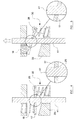
Figure 4 is a schematic cut-away view of thepiston 41, lockingelement 17,release guide 33, first andsecond springs lower leg 28 of therelease pin 26. - Although the
first spring 16 extends all the way around thepiston 41, the force exerted by thefirst spring 16 is primarily on the left-hand side of the locking element (in the orientation shown infigure 4 ), and thefirst spring 16 is therefore schematically shown as a compression spring located on the left-hand side of the piston 41 (i.e. the side opposite to the side on which theprojection 10 protrudes from the housing 2). - Similarly, although the
second spring 30 may include only a single coil, thisspring 30 is schematically represented by a further compression spring located on the right-hand side of the piston 41 (i.e. the side on which theprojection 10 protrudes from the housing 2). - The external diameter of the
piston 41 is preferably only slightly smaller than the internal diameter of themain aperture 25 passing through the lockingelement 17. The region where thepiston 41 passes through themain aperture 25 of the lockingelement 17 is enlarged infigure 4 . It can be seen that, because themain aperture 25 is formed to be at an angle with the longitudinal axis of the lockingelement 17, the internal edges of themain aperture 25 are pressed firmly against the outer surface of thepiston 41, thus holding thepiston 41 in place with respect to the lockingelement 17. - As discussed above, the
protrusion 18 of the lockingelement 17 is held in place with respect to the housing by thelower leg 28 of therelease pin 26. The lockingelement 17 is therefore restrained only to pivoting around the axis defined by thelower leg 28 of therelease pin 26. Thefirst spring 16 presses down on the free end of the locking element 17 (i.e. the end of the left, in the orientation shown infigure 4 ) with sufficient force to prevent thelocking element 17 from pivoting clockwise around this axis. The lockingelement 17 is therefore held in its initial position. -
Figure 4 shows the initial configuration of the locking arrangement. It will be understood that, because the lockingelement 17 grips thepiston 41 firmly, the piston is locked in place with respect to thelocking arrangement 1. - When the bonnet lifter is activated, the
piston 41 is driven upwardly by the pressure of gas in thecylinder 40. As the cylinder is driver upwardly, this will have the effect of lifting the lockingelement 17 in an upward direction. The lockingelement 17 will therefore pivot upwardly around thelower leg 28 of therelease pin 26, compressing thefirst spring 16 in the process. As the lockingelement 17 is tilted, the axis of itsmain aperture 25 will completely or substantially align with that of thepiston 41, so thepiston 41 may slide easily through themain aperture 25. Once again, a close-up view of the region where thepiston 41 passes through the central aperture of the lockingelement 17 is shown infigure 5 . - The strength of the
first spring 16 is chosen so that, as thepiston 41 is driven upwardly by the pressure of gas in thecylinder 40, the lockingelement 17 remains in the "unlocked" position shown infigure 5 , thus allowing thepiston 41 to be driven upwardly with little or no resistance from the lockingarrangement 1. - It will be understood that the
piston 41 must be driven with at least a threshold force in order for the lockingelement 17 to be moved from the locked position to the unlocked position, as the biasing force of thefirst spring 16 must be overcome for this movement to take place. The cylinder/piston arrangement piston 41 is driven with a force equal to or exceeding the threshold force. - If the upward motion of the
piston 41 is halted, for instance by the impact of a pedestrian on the bonnet that is being lifted by thepiston 41, the lifting effect of thepiston 41 on the lockingelement 17 will cease. Thefirst spring 16 will then return the lockingelement 17 to its original "locked position", as shown infigure 6 , and thepiston 41 will once again be locked in position with respect to thehousing 2. - It will therefore be understood that, when the upward motion of the
piston 41 cease, thepiston 41 will automatically lock in place, and will not continue to rise in an upward direction. Therefore, when a pedestrian strikes the bonnet of a vehicle, if the bonnet lifter has not fully completed its lifting operation, the bonnet will in any event stop at that point, and will not rise any further. This will help to avoid any injuries to a pedestrian that might arise from the bonnet continuing to move upwardly after the pedestrian has struck the bonnet. The piston will, however, be firmly locked against downward movement, and will therefore the rear end of the bonnet will be held in place as the bonnet deforms to absorb the momentum of the pedestrian. - Once the bonnet lifter has been activated, it may be desired to return the bonnet to its original position, so that the view out of the vehicle's windscreen is not obscured, for instance to allow the vehicle to be driven to a workshop/garage for repairs to be carried out and/or for the bonnet lifter to be re-set.
- In order to do this, the
release pin 26 is firstly removed from the lockingarrangement 1. This means that the lockingelement 17 is therefore free to "float" within thehousing 2 and is not constrained to pivot around the retainingaperture 24 formed through itsprotrusion 18. The lockingelement 17 will, however, initially remain in its locked position due to the interaction of thefirst spring 16, which presses down on the left-hand side of the locking element 17 (in the orientation shown in the figures), and thesecond spring 30, which presses upwardly on the underside of the right-hand side of the lockingelement 17. The lockingelement 17 is therefore held in a position in which it is rotated counter-clockwise as far as possible, so the internal edges of themain aperture 25 of the locking element grip firmly against the outer surface of thepiston 41. - If the
piston 41 is then driven downwardly (for instance, by manually pressing on the upper end of thepiston 41, or directly on the top surface of the bonnet), the effect will be to push thelocking element 17 downwardly within thehousing 2. As this occurs, the lockingelement 17 will be pushed down onto the upper surface of therelease guide 33. Because of the inclinedtop surface 37 of therelease guide 33, the lockingelement 17 will be forced into the "unlocked" orientation with respect to thepiston 41, and thepiston 41 may therefore be pushed downwardly by a sufficient amount that the bonnet does not obscure the view out of the vehicle's windscreen. When thepiston 41 has been pushed down far enough, the piston may be released, and the first andsecond springs locking element 17 into the locked position, as shown infigure 8 . Once thepiston 41 has been pressed down, therefore, the lockingarrangement 1 will lock thepiston 41 in place once again and prevent thepiston 41 from rising upwardly. - Whilst the above example has been explained in relation to a bonnet lifter, it will be understood that locking arrangements of this type may be used in other situations, and particularly in other vehicle safety systems, for instance in a rollover bar or a seat belt system. A skilled person will appreciate how the locking arrangement may be incorporated into systems such as this, to ensure that the piston is placed into a locked state when movement of the piston is halted at any point along its travel path, even if the normal motion of the piston has not been completed.
- It will be appreciated that the present invention provides a robust and adaptable locking arrangement which will find utility in many situations, in particular in vehicle safety systems.
- In the present specification "comprise" means "includes or consists of" and "comprising" means "including or consisting of".
- The features disclosed in the foregoing description, or the following claims, or the accompanying drawings, expressed in their specific forms or in terms of a means for performing the disclosed function, or a method or process for attaining the disclosed result, as appropriate, may, separately, or in any combination of such features, be utilised for realising the invention in diverse forms thereof.
Claims (15)
- A piston mechanism for a vehicle safety system comprising:a piston and associated drive mechanism for driving the piston in a driving direction; anda locking arrangement positioned around or adjacent the piston, the locking mechanism being substantially fixed in place with respect to the drive mechanism and including a locking element, the locking element being moveable from a first position or orientation, in which the piston may move in the driving direction with respect to the locking arrangement in a substantially unimpeded manner, and a second position or configuration, in which movement of the piston in the driving direction with respect to the locking arrangement is impeded.
- A piston mechanism according to claim 1, comprising a housing located entirely or substantially around the piston.
- A piston mechanism according to claim 2, wherein the locking element is located within the housing.
- A piston mechanism according to any preceding claim wherein, in the second position, a part of the locking element presses against the external surface of the piston.
- A piston mechanism according to any preceding claim wherein the locking element has an aperture formed therethrough, with the piston passing through the aperture.
- A piston mechanism according to claim 5 wherein, in the first position, a longitudinal axis of the aperture is substantially aligned with the longitudinal axis of the piston, and in the second position, the longitudinal axis of the aperture is at an angle to the longitudinal axis of the piston, so that one or more inner edges of the aperture press against an external surface of the piston.
- A piston mechanism according to any preceding claim, wherein a first biasing element is provided to bias the locking element into the second position.
- A piston mechanism according to any preceding claim, wherein the locking element is initially in the second position, and driving of the piston in the driving direction by the drive mechanism moves the locking element into the first position.
- A piston according to claim 8, wherein movement of the piston in the driving direction, driven by a driving force below a threshold force, will not move the locking element into the first position, and the drive mechanism is adapted to drive the piston with a driving force which is at least greater than the threshold force.
- A piston mechanism according to claim 8 or 9, when dependent upon claim 7 wherein, after driving of the piston by the drive mechanism has commenced, the biasing element is operable to return the locking element to the second position if the motion of the piston with respect to the drive mechanism is halted by an external force.
- A piston mechanism according to any preceding claim wherein, after the piston has been driven in the drive direction by a distance with respect to the drive mechanism and the locking mechanism is in the second position, applying a return force to the piston, in a direction substantially opposite to the driving direction, will force the locking element against a release guide, thus forcing the locking element into the first position.
- A piston mechanism according to claim 11, wherein the locking element rotates to move between the first and second positions, and wherein the release guide is shaped so that, when the locking element is forced against the release guide, the locking element must rotate into the first position.
- A piston mechanism according to claim 11 or 12, further comprising a retaining element which initially prevents the locking element from being forced against the release guide, but which may be removed or altered to allow the locking element to be forced against the release guide.
- A piston mechanism according to claim 13, wherein the retaining element initially holds at least a part of the locking mechanism in place.
- A piston mechanism according to one of claims 11 to 14 further comprising a second biasing element, which is operable to separate the locking element from the release guide.
Priority Applications (1)
| Application Number | Priority Date | Filing Date | Title |
|---|---|---|---|
| EP20110167431 EP2527211B1 (en) | 2011-05-25 | 2011-05-25 | Piston mechanism for a vehicle safety system |
Applications Claiming Priority (1)
| Application Number | Priority Date | Filing Date | Title |
|---|---|---|---|
| EP20110167431 EP2527211B1 (en) | 2011-05-25 | 2011-05-25 | Piston mechanism for a vehicle safety system |
Publications (2)
| Publication Number | Publication Date |
|---|---|
| EP2527211A1 true EP2527211A1 (en) | 2012-11-28 |
| EP2527211B1 EP2527211B1 (en) | 2014-01-22 |
Family
ID=44816971
Family Applications (1)
| Application Number | Title | Priority Date | Filing Date |
|---|---|---|---|
| EP20110167431 Not-in-force EP2527211B1 (en) | 2011-05-25 | 2011-05-25 | Piston mechanism for a vehicle safety system |
Country Status (1)
| Country | Link |
|---|---|
| EP (1) | EP2527211B1 (en) |
Citations (3)
| Publication number | Priority date | Publication date | Assignee | Title |
|---|---|---|---|---|
| US20050264036A1 (en) * | 2004-05-25 | 2005-12-01 | Kramarczyk Mark A | Hood elevation system |
| FR2920840A1 (en) * | 2007-09-07 | 2009-03-13 | Snpe Sa | CURRENT CYLINDER, IN PARTICULAR FOR A MOTOR VEHICLE SAFETY SYSTEM FOR PEDESTRIAN PROTECTION. |
| US20090152899A1 (en) * | 2005-09-15 | 2009-06-18 | Gm Global Technology Operations, Inc. | Body for a motor vehicle |
-
2011
- 2011-05-25 EP EP20110167431 patent/EP2527211B1/en not_active Not-in-force
Patent Citations (3)
| Publication number | Priority date | Publication date | Assignee | Title |
|---|---|---|---|---|
| US20050264036A1 (en) * | 2004-05-25 | 2005-12-01 | Kramarczyk Mark A | Hood elevation system |
| US20090152899A1 (en) * | 2005-09-15 | 2009-06-18 | Gm Global Technology Operations, Inc. | Body for a motor vehicle |
| FR2920840A1 (en) * | 2007-09-07 | 2009-03-13 | Snpe Sa | CURRENT CYLINDER, IN PARTICULAR FOR A MOTOR VEHICLE SAFETY SYSTEM FOR PEDESTRIAN PROTECTION. |
Also Published As
| Publication number | Publication date |
|---|---|
| EP2527211B1 (en) | 2014-01-22 |
Similar Documents
| Publication | Publication Date | Title |
|---|---|---|
| EP2493713B1 (en) | Device for prevention of door opening during roll-over | |
| US10308275B2 (en) | Steering column with longitudinal stop having an adjustable release function in the event of a crash | |
| CN109795545B (en) | Steering device | |
| US8882093B2 (en) | Handheld clamping tool | |
| JP6518099B2 (en) | Steering device | |
| US10434974B2 (en) | Hood lifting assembly | |
| US10532762B2 (en) | Energy-absorbing steering column | |
| CN107235026B (en) | vehicle bumper | |
| CN106703578B (en) | Upspring structure for car engine cover and the method that bounces car engine cover | |
| CN109795542B (en) | Steering device | |
| JP4574711B2 (en) | Passive pedestrian protection hood hinge | |
| JP2011208738A (en) | Actuator | |
| JP6398376B2 (en) | Pop-up hood device for vehicle | |
| CN106536298B (en) | Brake pedal device for automobile | |
| EP3684993B1 (en) | Motor vehicle latch | |
| US9283925B2 (en) | Integrated active hinge mechanism | |
| EP2527211B1 (en) | Piston mechanism for a vehicle safety system | |
| JP2018165108A (en) | Steering device | |
| KR101610948B1 (en) | Supporting type hood hinge lifting device | |
| EP3401472A1 (en) | Resettable locking system for a door handle assembly | |
| JP5335049B2 (en) | Accelerator pedal misoperation prevention device | |
| JP4431500B2 (en) | Locking device for automobile bonnet that makes it possible to reduce the impact of pedestrians | |
| US9352672B2 (en) | Inertial latch system for a vehicle seat | |
| CN105984483B (en) | It is a kind of to prevent the device of the passive crumple of steering column and prevent passive crumple method | |
| WO2011162675A1 (en) | Pedestrian protection device for a vehicle |
Legal Events
| Date | Code | Title | Description |
|---|---|---|---|
| PUAI | Public reference made under article 153(3) epc to a published international application that has entered the european phase |
Free format text: ORIGINAL CODE: 0009012 |
|
| AK | Designated contracting states |
Kind code of ref document: A1 Designated state(s): AL AT BE BG CH CY CZ DE DK EE ES FI FR GB GR HR HU IE IS IT LI LT LU LV MC MK MT NL NO PL PT RO RS SE SI SK SM TR |
|
| AX | Request for extension of the european patent |
Extension state: BA ME |
|
| 17P | Request for examination filed |
Effective date: 20130423 |
|
| 17Q | First examination report despatched |
Effective date: 20130527 |
|
| GRAP | Despatch of communication of intention to grant a patent |
Free format text: ORIGINAL CODE: EPIDOSNIGR1 |
|
| INTG | Intention to grant announced |
Effective date: 20130821 |
|
| GRAS | Grant fee paid |
Free format text: ORIGINAL CODE: EPIDOSNIGR3 |
|
| GRAA | (expected) grant |
Free format text: ORIGINAL CODE: 0009210 |
|
| AK | Designated contracting states |
Kind code of ref document: B1 Designated state(s): AL AT BE BG CH CY CZ DE DK EE ES FI FR GB GR HR HU IE IS IT LI LT LU LV MC MK MT NL NO PL PT RO RS SE SI SK SM TR |
|
| REG | Reference to a national code |
Ref country code: GB Ref legal event code: FG4D |
|
| REG | Reference to a national code |
Ref country code: CH Ref legal event code: EP |
|
| REG | Reference to a national code |
Ref country code: AT Ref legal event code: REF Ref document number: 650633 Country of ref document: AT Kind code of ref document: T Effective date: 20140215 |
|
| REG | Reference to a national code |
Ref country code: IE Ref legal event code: FG4D |
|
| REG | Reference to a national code |
Ref country code: DE Ref legal event code: R096 Ref document number: 602011004764 Country of ref document: DE Effective date: 20140306 |
|
| REG | Reference to a national code |
Ref country code: NL Ref legal event code: VDEP Effective date: 20140122 |
|
| REG | Reference to a national code |
Ref country code: AT Ref legal event code: MK05 Ref document number: 650633 Country of ref document: AT Kind code of ref document: T Effective date: 20140122 |
|
| REG | Reference to a national code |
Ref country code: LT Ref legal event code: MG4D |
|
| PG25 | Lapsed in a contracting state [announced via postgrant information from national office to epo] |
Ref country code: IS Free format text: LAPSE BECAUSE OF FAILURE TO SUBMIT A TRANSLATION OF THE DESCRIPTION OR TO PAY THE FEE WITHIN THE PRESCRIBED TIME-LIMIT Effective date: 20140522 Ref country code: NO Free format text: LAPSE BECAUSE OF FAILURE TO SUBMIT A TRANSLATION OF THE DESCRIPTION OR TO PAY THE FEE WITHIN THE PRESCRIBED TIME-LIMIT Effective date: 20140422 Ref country code: LT Free format text: LAPSE BECAUSE OF FAILURE TO SUBMIT A TRANSLATION OF THE DESCRIPTION OR TO PAY THE FEE WITHIN THE PRESCRIBED TIME-LIMIT Effective date: 20140122 |
|
| PG25 | Lapsed in a contracting state [announced via postgrant information from national office to epo] |
Ref country code: AT Free format text: LAPSE BECAUSE OF FAILURE TO SUBMIT A TRANSLATION OF THE DESCRIPTION OR TO PAY THE FEE WITHIN THE PRESCRIBED TIME-LIMIT Effective date: 20140122 Ref country code: NL Free format text: LAPSE BECAUSE OF FAILURE TO SUBMIT A TRANSLATION OF THE DESCRIPTION OR TO PAY THE FEE WITHIN THE PRESCRIBED TIME-LIMIT Effective date: 20140122 Ref country code: CY Free format text: LAPSE BECAUSE OF FAILURE TO SUBMIT A TRANSLATION OF THE DESCRIPTION OR TO PAY THE FEE WITHIN THE PRESCRIBED TIME-LIMIT Effective date: 20140122 Ref country code: FI Free format text: LAPSE BECAUSE OF FAILURE TO SUBMIT A TRANSLATION OF THE DESCRIPTION OR TO PAY THE FEE WITHIN THE PRESCRIBED TIME-LIMIT Effective date: 20140122 Ref country code: ES Free format text: LAPSE BECAUSE OF FAILURE TO SUBMIT A TRANSLATION OF THE DESCRIPTION OR TO PAY THE FEE WITHIN THE PRESCRIBED TIME-LIMIT Effective date: 20140122 Ref country code: PT Free format text: LAPSE BECAUSE OF FAILURE TO SUBMIT A TRANSLATION OF THE DESCRIPTION OR TO PAY THE FEE WITHIN THE PRESCRIBED TIME-LIMIT Effective date: 20140522 Ref country code: SE Free format text: LAPSE BECAUSE OF FAILURE TO SUBMIT A TRANSLATION OF THE DESCRIPTION OR TO PAY THE FEE WITHIN THE PRESCRIBED TIME-LIMIT Effective date: 20140122 |
|
| PG25 | Lapsed in a contracting state [announced via postgrant information from national office to epo] |
Ref country code: LV Free format text: LAPSE BECAUSE OF FAILURE TO SUBMIT A TRANSLATION OF THE DESCRIPTION OR TO PAY THE FEE WITHIN THE PRESCRIBED TIME-LIMIT Effective date: 20140122 Ref country code: RS Free format text: LAPSE BECAUSE OF FAILURE TO SUBMIT A TRANSLATION OF THE DESCRIPTION OR TO PAY THE FEE WITHIN THE PRESCRIBED TIME-LIMIT Effective date: 20140122 Ref country code: HR Free format text: LAPSE BECAUSE OF FAILURE TO SUBMIT A TRANSLATION OF THE DESCRIPTION OR TO PAY THE FEE WITHIN THE PRESCRIBED TIME-LIMIT Effective date: 20140122 Ref country code: BE Free format text: LAPSE BECAUSE OF FAILURE TO SUBMIT A TRANSLATION OF THE DESCRIPTION OR TO PAY THE FEE WITHIN THE PRESCRIBED TIME-LIMIT Effective date: 20140122 |
|
| REG | Reference to a national code |
Ref country code: DE Ref legal event code: R097 Ref document number: 602011004764 Country of ref document: DE |
|
| PG25 | Lapsed in a contracting state [announced via postgrant information from national office to epo] |
Ref country code: CZ Free format text: LAPSE BECAUSE OF FAILURE TO SUBMIT A TRANSLATION OF THE DESCRIPTION OR TO PAY THE FEE WITHIN THE PRESCRIBED TIME-LIMIT Effective date: 20140122 Ref country code: EE Free format text: LAPSE BECAUSE OF FAILURE TO SUBMIT A TRANSLATION OF THE DESCRIPTION OR TO PAY THE FEE WITHIN THE PRESCRIBED TIME-LIMIT Effective date: 20140122 Ref country code: DK Free format text: LAPSE BECAUSE OF FAILURE TO SUBMIT A TRANSLATION OF THE DESCRIPTION OR TO PAY THE FEE WITHIN THE PRESCRIBED TIME-LIMIT Effective date: 20140122 Ref country code: RO Free format text: LAPSE BECAUSE OF FAILURE TO SUBMIT A TRANSLATION OF THE DESCRIPTION OR TO PAY THE FEE WITHIN THE PRESCRIBED TIME-LIMIT Effective date: 20140122 |
|
| PG25 | Lapsed in a contracting state [announced via postgrant information from national office to epo] |
Ref country code: SK Free format text: LAPSE BECAUSE OF FAILURE TO SUBMIT A TRANSLATION OF THE DESCRIPTION OR TO PAY THE FEE WITHIN THE PRESCRIBED TIME-LIMIT Effective date: 20140122 Ref country code: PL Free format text: LAPSE BECAUSE OF FAILURE TO SUBMIT A TRANSLATION OF THE DESCRIPTION OR TO PAY THE FEE WITHIN THE PRESCRIBED TIME-LIMIT Effective date: 20140122 |
|
| PLBE | No opposition filed within time limit |
Free format text: ORIGINAL CODE: 0009261 |
|
| STAA | Information on the status of an ep patent application or granted ep patent |
Free format text: STATUS: NO OPPOSITION FILED WITHIN TIME LIMIT |
|
| 26N | No opposition filed |
Effective date: 20141023 |
|
| PG25 | Lapsed in a contracting state [announced via postgrant information from national office to epo] |
Ref country code: LU Free format text: LAPSE BECAUSE OF FAILURE TO SUBMIT A TRANSLATION OF THE DESCRIPTION OR TO PAY THE FEE WITHIN THE PRESCRIBED TIME-LIMIT Effective date: 20140525 |
|
| REG | Reference to a national code |
Ref country code: CH Ref legal event code: PL |
|
| PG25 | Lapsed in a contracting state [announced via postgrant information from national office to epo] |
Ref country code: MC Free format text: LAPSE BECAUSE OF FAILURE TO SUBMIT A TRANSLATION OF THE DESCRIPTION OR TO PAY THE FEE WITHIN THE PRESCRIBED TIME-LIMIT Effective date: 20140122 Ref country code: CH Free format text: LAPSE BECAUSE OF NON-PAYMENT OF DUE FEES Effective date: 20140531 Ref country code: LI Free format text: LAPSE BECAUSE OF NON-PAYMENT OF DUE FEES Effective date: 20140531 |
|
| REG | Reference to a national code |
Ref country code: DE Ref legal event code: R097 Ref document number: 602011004764 Country of ref document: DE Effective date: 20141023 |
|
| REG | Reference to a national code |
Ref country code: IE Ref legal event code: MM4A |
|
| REG | Reference to a national code |
Ref country code: FR Ref legal event code: PLFP Year of fee payment: 5 |
|
| PG25 | Lapsed in a contracting state [announced via postgrant information from national office to epo] |
Ref country code: IE Free format text: LAPSE BECAUSE OF NON-PAYMENT OF DUE FEES Effective date: 20140525 |
|
| PG25 | Lapsed in a contracting state [announced via postgrant information from national office to epo] |
Ref country code: SI Free format text: LAPSE BECAUSE OF FAILURE TO SUBMIT A TRANSLATION OF THE DESCRIPTION OR TO PAY THE FEE WITHIN THE PRESCRIBED TIME-LIMIT Effective date: 20140122 |
|
| PGFP | Annual fee paid to national office [announced via postgrant information from national office to epo] |
Ref country code: GB Payment date: 20150428 Year of fee payment: 5 Ref country code: DE Payment date: 20150306 Year of fee payment: 5 |
|
| PGFP | Annual fee paid to national office [announced via postgrant information from national office to epo] |
Ref country code: FR Payment date: 20150330 Year of fee payment: 5 |
|
| PG25 | Lapsed in a contracting state [announced via postgrant information from national office to epo] |
Ref country code: MT Free format text: LAPSE BECAUSE OF FAILURE TO SUBMIT A TRANSLATION OF THE DESCRIPTION OR TO PAY THE FEE WITHIN THE PRESCRIBED TIME-LIMIT Effective date: 20140122 |
|
| PG25 | Lapsed in a contracting state [announced via postgrant information from national office to epo] |
Ref country code: SM Free format text: LAPSE BECAUSE OF FAILURE TO SUBMIT A TRANSLATION OF THE DESCRIPTION OR TO PAY THE FEE WITHIN THE PRESCRIBED TIME-LIMIT Effective date: 20140122 |
|
| PG25 | Lapsed in a contracting state [announced via postgrant information from national office to epo] |
Ref country code: GR Free format text: LAPSE BECAUSE OF FAILURE TO SUBMIT A TRANSLATION OF THE DESCRIPTION OR TO PAY THE FEE WITHIN THE PRESCRIBED TIME-LIMIT Effective date: 20140423 Ref country code: IT Free format text: LAPSE BECAUSE OF FAILURE TO SUBMIT A TRANSLATION OF THE DESCRIPTION OR TO PAY THE FEE WITHIN THE PRESCRIBED TIME-LIMIT Effective date: 20140122 Ref country code: BG Free format text: LAPSE BECAUSE OF FAILURE TO SUBMIT A TRANSLATION OF THE DESCRIPTION OR TO PAY THE FEE WITHIN THE PRESCRIBED TIME-LIMIT Effective date: 20140122 |
|
| PG25 | Lapsed in a contracting state [announced via postgrant information from national office to epo] |
Ref country code: TR Free format text: LAPSE BECAUSE OF FAILURE TO SUBMIT A TRANSLATION OF THE DESCRIPTION OR TO PAY THE FEE WITHIN THE PRESCRIBED TIME-LIMIT Effective date: 20140122 Ref country code: HU Free format text: LAPSE BECAUSE OF FAILURE TO SUBMIT A TRANSLATION OF THE DESCRIPTION OR TO PAY THE FEE WITHIN THE PRESCRIBED TIME-LIMIT; INVALID AB INITIO Effective date: 20110525 |
|
| REG | Reference to a national code |
Ref country code: DE Ref legal event code: R119 Ref document number: 602011004764 Country of ref document: DE |
|
| GBPC | Gb: european patent ceased through non-payment of renewal fee |
Effective date: 20160525 |
|
| REG | Reference to a national code |
Ref country code: FR Ref legal event code: ST Effective date: 20170131 |
|
| PG25 | Lapsed in a contracting state [announced via postgrant information from national office to epo] |
Ref country code: FR Free format text: LAPSE BECAUSE OF NON-PAYMENT OF DUE FEES Effective date: 20160531 Ref country code: DE Free format text: LAPSE BECAUSE OF NON-PAYMENT OF DUE FEES Effective date: 20161201 |
|
| PG25 | Lapsed in a contracting state [announced via postgrant information from national office to epo] |
Ref country code: GB Free format text: LAPSE BECAUSE OF NON-PAYMENT OF DUE FEES Effective date: 20160525 |
|
| PG25 | Lapsed in a contracting state [announced via postgrant information from national office to epo] |
Ref country code: MK Free format text: LAPSE BECAUSE OF FAILURE TO SUBMIT A TRANSLATION OF THE DESCRIPTION OR TO PAY THE FEE WITHIN THE PRESCRIBED TIME-LIMIT Effective date: 20140122 |
|
| PG25 | Lapsed in a contracting state [announced via postgrant information from national office to epo] |
Ref country code: AL Free format text: LAPSE BECAUSE OF FAILURE TO SUBMIT A TRANSLATION OF THE DESCRIPTION OR TO PAY THE FEE WITHIN THE PRESCRIBED TIME-LIMIT Effective date: 20140122 |