EP2527154B3 - Combined ink family keying for an ink cartridge - Google Patents
Combined ink family keying for an ink cartridge Download PDFInfo
- Publication number
- EP2527154B3 EP2527154B3 EP12181781.1A EP12181781A EP2527154B3 EP 2527154 B3 EP2527154 B3 EP 2527154B3 EP 12181781 A EP12181781 A EP 12181781A EP 2527154 B3 EP2527154 B3 EP 2527154B3
- Authority
- EP
- European Patent Office
- Prior art keywords
- ink cartridge
- carriage
- assembly
- ink
- cartridge
- Prior art date
- Legal status (The legal status is an assumption and is not a legal conclusion. Google has not performed a legal analysis and makes no representation as to the accuracy of the status listed.)
- Active
Links
- 238000003780 insertion Methods 0.000 claims description 41
- 230000037431 insertion Effects 0.000 claims description 41
- 239000000976 ink Substances 0.000 description 74
- 238000000429 assembly Methods 0.000 description 4
- 230000000712 assembly Effects 0.000 description 4
- 239000007788 liquid Substances 0.000 description 3
- 238000004891 communication Methods 0.000 description 2
- 238000010304 firing Methods 0.000 description 2
- 230000003287 optical effect Effects 0.000 description 2
- 238000009434 installation Methods 0.000 description 1
Images


Classifications
-
- B—PERFORMING OPERATIONS; TRANSPORTING
- B41—PRINTING; LINING MACHINES; TYPEWRITERS; STAMPS
- B41J—TYPEWRITERS; SELECTIVE PRINTING MECHANISMS, i.e. MECHANISMS PRINTING OTHERWISE THAN FROM A FORME; CORRECTION OF TYPOGRAPHICAL ERRORS
- B41J2/00—Typewriters or selective printing mechanisms characterised by the printing or marking process for which they are designed
- B41J2/005—Typewriters or selective printing mechanisms characterised by the printing or marking process for which they are designed characterised by bringing liquid or particles selectively into contact with a printing material
- B41J2/01—Ink jet
- B41J2/17—Ink jet characterised by ink handling
- B41J2/175—Ink supply systems ; Circuit parts therefor
- B41J2/17503—Ink cartridges
- B41J2/17543—Cartridge presence detection or type identification
- B41J2/1755—Cartridge presence detection or type identification mechanically
-
- B—PERFORMING OPERATIONS; TRANSPORTING
- B41—PRINTING; LINING MACHINES; TYPEWRITERS; STAMPS
- B41J—TYPEWRITERS; SELECTIVE PRINTING MECHANISMS, i.e. MECHANISMS PRINTING OTHERWISE THAN FROM A FORME; CORRECTION OF TYPOGRAPHICAL ERRORS
- B41J2/00—Typewriters or selective printing mechanisms characterised by the printing or marking process for which they are designed
- B41J2/005—Typewriters or selective printing mechanisms characterised by the printing or marking process for which they are designed characterised by bringing liquid or particles selectively into contact with a printing material
- B41J2/01—Ink jet
- B41J2/17—Ink jet characterised by ink handling
- B41J2/175—Ink supply systems ; Circuit parts therefor
- B41J2/17503—Ink cartridges
- B41J2/17513—Inner structure
-
- B—PERFORMING OPERATIONS; TRANSPORTING
- B41—PRINTING; LINING MACHINES; TYPEWRITERS; STAMPS
- B41J—TYPEWRITERS; SELECTIVE PRINTING MECHANISMS, i.e. MECHANISMS PRINTING OTHERWISE THAN FROM A FORME; CORRECTION OF TYPOGRAPHICAL ERRORS
- B41J2/00—Typewriters or selective printing mechanisms characterised by the printing or marking process for which they are designed
- B41J2/005—Typewriters or selective printing mechanisms characterised by the printing or marking process for which they are designed characterised by bringing liquid or particles selectively into contact with a printing material
- B41J2/01—Ink jet
- B41J2/17—Ink jet characterised by ink handling
- B41J2/175—Ink supply systems ; Circuit parts therefor
- B41J2/17503—Ink cartridges
- B41J2/1752—Mounting within the printer
-
- B—PERFORMING OPERATIONS; TRANSPORTING
- B41—PRINTING; LINING MACHINES; TYPEWRITERS; STAMPS
- B41J—TYPEWRITERS; SELECTIVE PRINTING MECHANISMS, i.e. MECHANISMS PRINTING OTHERWISE THAN FROM A FORME; CORRECTION OF TYPOGRAPHICAL ERRORS
- B41J2/00—Typewriters or selective printing mechanisms characterised by the printing or marking process for which they are designed
- B41J2/005—Typewriters or selective printing mechanisms characterised by the printing or marking process for which they are designed characterised by bringing liquid or particles selectively into contact with a printing material
- B41J2/01—Ink jet
- B41J2/17—Ink jet characterised by ink handling
- B41J2/175—Ink supply systems ; Circuit parts therefor
- B41J2/17503—Ink cartridges
- B41J2/17543—Cartridge presence detection or type identification
- B41J2/17546—Cartridge presence detection or type identification electronically
-
- B—PERFORMING OPERATIONS; TRANSPORTING
- B41—PRINTING; LINING MACHINES; TYPEWRITERS; STAMPS
- B41J—TYPEWRITERS; SELECTIVE PRINTING MECHANISMS, i.e. MECHANISMS PRINTING OTHERWISE THAN FROM A FORME; CORRECTION OF TYPOGRAPHICAL ERRORS
- B41J2/00—Typewriters or selective printing mechanisms characterised by the printing or marking process for which they are designed
- B41J2/005—Typewriters or selective printing mechanisms characterised by the printing or marking process for which they are designed characterised by bringing liquid or particles selectively into contact with a printing material
- B41J2/01—Ink jet
- B41J2/17—Ink jet characterised by ink handling
- B41J2/175—Ink supply systems ; Circuit parts therefor
- B41J2/17503—Ink cartridges
- B41J2/17553—Outer structure
-
- B—PERFORMING OPERATIONS; TRANSPORTING
- B41—PRINTING; LINING MACHINES; TYPEWRITERS; STAMPS
- B41J—TYPEWRITERS; SELECTIVE PRINTING MECHANISMS, i.e. MECHANISMS PRINTING OTHERWISE THAN FROM A FORME; CORRECTION OF TYPOGRAPHICAL ERRORS
- B41J2/00—Typewriters or selective printing mechanisms characterised by the printing or marking process for which they are designed
- B41J2/005—Typewriters or selective printing mechanisms characterised by the printing or marking process for which they are designed characterised by bringing liquid or particles selectively into contact with a printing material
- B41J2/01—Ink jet
- B41J2/17—Ink jet characterised by ink handling
- B41J2/175—Ink supply systems ; Circuit parts therefor
- B41J2/17593—Supplying ink in a solid state
Definitions
- Ink jet printers operate by ejecting tiny drops of ink from a printhead onto a printing medium, such as paper.
- the printhead generally includes a nozzle plate having a plurality of nozzles through which tiny ink droplets are ejected onto the paper to collectively create an image.
- the printhead includes a plurality of ink firing chambers, each fluidically connected to an associated nozzle through a bore. Within each firing chamber is a heat-generating resistor that is selectively energized to heat the ink in the chamber, which creates a bubble. As the bubble expands, some of the ink is forced through the bore out of the nozzle and onto the paper.
- the printhead and nozzles are often incorporated into a printer carriage inside the printer.
- the printhead may be integrated into the carriage, or may be a removably detached insert.
- the ink is supplied to the printhead by a cartridge that is inserted into, and detachably mounted, within the printhead and carriage.
- the cartridge is fluidically and electrically connected to the printhead and carriage through fluidic and electrical interfaces. The reliability of the cartridge and printhead assembly, and ultimately the quality of the printed image, depends in part on the proper alignment and engagement of the fluidic and electrical interfaces.
- communication loss e.g., print command signal loss
- a loss in print quality due to a poor fluidic connection.
- known cartridge designs have an incorporated datum feature that provides a point of reference for insertion of the ink cartridge. In this way, the cartridge is properly positioned and engaged within the carriage and/or printhead assembly to provide adequate fluidic and electrical interconnects.
- known ink jet cartridges may include a keying feature to prevent the insertion of an incompatible ink cartridge.
- ink cartridges are universal and can be used on a number of different printer families. Some ink cartridges, however, contain inks that may be chemically incompatible with other ink types. If incompatible inks come into contact with one another, they could congeal and damage the printhead and nozzle assembly.
- ink jet cartridges may vary with respect to size and shape, they have historically been large enough in width and surface area to accommodate both datum and keying features. However, it has become increasingly important todesign inkjet cartridges as narrow as possible because the overall width of the cartridge influences the width of the printer. With the onset of narrower ink cartridges there is no longer the width available for both the datum and keying features.
- EP1352748 discloses a recording liquid container for containing liquid to be supplied to recording means.
- the recording liquid container is detachably mountable to a mounting portion of a recording device.
- an ink cartridge comprising an insertion key located on a back edge portion of the ink cartridge, the insertion key being configured to provide a pivotal reference point for insertion of the ink cartridge into a carriage assembly and to prevent the insertion of the ink cartridge into a carriage assembly that does not include a matching key configuration; an electrical interconnect configured to establish electrical connectivity between the ink cartridge and the carriage assembly; and an ink supply port configured to be fluidically connected to a printhead assembly, wherein the electrical interconnect and the ink supply port are located on the same surface of the ink cartridge.
- a system comprising a carriage assembly; a printhead assembly; and an ink cartridge according to the first aspect of the invention, wherein the carriage assembly is configured to accept the ink cartridge.
- the ink cartridge includes an ink supply port, an electrical interconnect, and an out-of-ink prism.
- the combined datum and keying feature i.e., "the insertion key”
- the insertion key serves as a pivotal reference point to guide the positioning of the ink cartridge into a printer carriage. In this way, the ink supply port, the electrical interconnect, and the out-of-ink prism are properly aligned with respect to the printhead assembly and the printer carriage, which assures proper fluidic and electrical communication.
- Figure 1 illustrates an exemplary ink jet printer 10 having at least one ink cartridge 12 mounted within a printhead assembly 14 and a carriage 16.
- Ink droplets are ejected onto a printing medium, such as paper 18, through the printhead, which generally includes a plurality of nozzles.
- the printhead and nozzles can be incorporated into the carriage 16, integrated into the ink cartridge 12, or as shown in Figure 1 , be a removable insert 14 positioned within the carriage 16.
- the ink cartridge 12 supplies ink to the printhead assembly 14, which selectively ejects drops of ink onto the paper 18 as the carriage 16 traverses back and forth from one side of the printer 10 to the other in a bi-directional fashion.
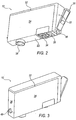
- Figure 2 illustrates an exemplary isometric view of an ink cartridge 12 showing a front edge portion 20, a bottom surface 22 and a first side 24.
- the ink cartridge 12 includes an ink supply port 26, an electrical interconnect 28 and a retaining latch 30 for securing the ink cartridge 12 into the carriage 16 upon insertion.
- the retaining latch 30 extends across at least the front edge portion 20 of ink cartridge 12.
- the retaining latch 30 is a one-piece molded structure that covers the length of the front edge portion 20 and extends across a top surface 32.
- the ink supply port 26 and the electrical interconnect 28 are located on bottom surface 22 and engagingly connect to reciprocal receptacles (not shown) located in the printhead 14 and carriage 16, respectively. When engaged, the ink supply port 26 and the electrical interconnect 28 provide fluidic and electrical connectivity between the ink cartridge 12 and the printhead 14 and carriage 16.
- the bottom surface 22 of cartridge 12 further includes an out-of-ink prism 34 that works in combination with an optical sensor 36 (shown in Figures 1 and 6 ) in carriage 16 to sense when the ink cartridge 12 is out of ink.
- the optical sensor 36 includes an emitter and a detector, wherein the emitter emits lights into one side of the prism. If there is ink present in the cartridge 12, the emitted light is diffused by the ink and scatters into the cartridge 12 preventing light from reflecting back to the detector. If no ink is present in the cartridge 12, the emitted light is reflected back to the detector indicating that the cartridge 12 is empty.
- the out-of-ink prism 34 also includes a clear window that enables a user to view the amount of ink inside cartridge 12.
- Figure 3 illustrates another exemplary isometric view of ink cartridge 12, including top surface 32 and a back edge portion 38.
- the back edge portion 38 includes an insertion key 40 that provides a pivotal reference point for insertion of the cartridge 12 into carriage 16.
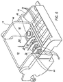
- the insertion of cartridge 12 into the printhead 14 and carriage 16 assembly is generally shown in Figures 4 and 5 , wherein Figure 4 illustrates the partial insertion of the cartridge 12 and Figure 5 illustrates the cartridge 12 being fully seated.
- Arrow 42 indicates the insertion path of ink cartridge 12 being inserted into the printhead 14 and carriage 16 assemblies, where the insertion key 40 engages a key receptacle 44 and provides a pivotal reference point.
- Ink cartridge 12 is then pivoted downward to engage the retaining latch 30 into the fully seated position shown in Figure 5 .
- the insertion key 40 assures proper alignment of ink cartridge 12 into the printhead 14 and carriage 16 assemblies enabling proper fluidic and electrical interconnects.
- ink supply port 26 is fluidically connected to a fluidic interconnect 46, which is located on printhead 14.
- electrical interconnect 28 is electrically connected to an electrical interconnect 48, which is located on carriage 16.
- insertion key 40 In addition to guiding the movement of cartridge 12 into the printhead 14 and carriage 16 assemblies, insertion key 40 also provides a keying feature to prevent the installation of an incorrect ink cartridge into carriage 16. In other words, insertion key 40 is configured such that ink cartridge 12 can only be inserted and properly seated into the printhead 14 and carriage 16 assemblies if there exists a receptacle having a matching reciprocal configuration.
- Figure 6 illustrates an exemplary printhead 14 and carriage 16 configurations wherein the printhead assembly 14 is inserted into carriage 16.
- the insertion key 40 as shown in Figure 3 has an inverted T-shape configuration that matches key receptacle 44 located on a back surface 50 of carriage 16, as shown in Figure 6 .
- the specific configuration of the insertion key 40 and the matching key receptacle 44 may vary and that the inverted T-shape configuration of insertion key 40 as shown in Figure 6 is exemplary.
- the insertion key 40 and the matching key receptacle on the carriage 16 may be in an L-shaped configuration.
- Figure 7 illustrates an isometric view of an exemplary carriage 16 wherein a front end surface 52 of carriage 16 includes an alignment post 54.
- the alignment post 54 is used in conjunction with an insertion slot 56 on ink cartridge 12 (shown in Figure 2 ) to further guide the insertion of ink cartridge 12 into carriage 16.
- Alignment post 54 is particularly advantageous in printer configurations in which the width of the carriage is greater than the width of the of the ink cartridge 12.
- the outward projection of alignment post 54 engages with insertion slot 56 to position and secure ink cartridge 12 into carriage 16, irrespective of printhead side walls 58 (shown in Figures 6 and 7 ).
Description
- Ink jet printers operate by ejecting tiny drops of ink from a printhead onto a printing medium, such as paper. The printhead generally includes a nozzle plate having a plurality of nozzles through which tiny ink droplets are ejected onto the paper to collectively create an image. To deliver ink to the nozzles, the printhead includes a plurality of ink firing chambers, each fluidically connected to an associated nozzle through a bore. Within each firing chamber is a heat-generating resistor that is selectively energized to heat the ink in the chamber, which creates a bubble. As the bubble expands, some of the ink is forced through the bore out of the nozzle and onto the paper. Though specific printer configurations may vary, the printhead and nozzles are often incorporated into a printer carriage inside the printer. The printhead may be integrated into the carriage, or may be a removably detached insert. In any case, the ink is supplied to the printhead by a cartridge that is inserted into, and detachably mounted, within the printhead and carriage. The cartridge is fluidically and electrically connected to the printhead and carriage through fluidic and electrical interfaces. The reliability of the cartridge and printhead assembly, and ultimately the quality of the printed image, depends in part on the proper alignment and engagement of the fluidic and electrical interfaces. Rough operation during insertion or removal of the cartridge by a user, or play between the cartridge and the printhead or carriage, can cause communication loss (e.g., print command signal loss) or a loss in print quality due to a poor fluidic connection. To secure the alignment and positioning of the cartridge within the carriage, known cartridge designs have an incorporated datum feature that provides a point of reference for insertion of the ink cartridge. In this way, the cartridge is properly positioned and engaged within the carriage and/or printhead assembly to provide adequate fluidic and electrical interconnects.
- In addition to datum features, known ink jet cartridges may include a keying feature to prevent the insertion of an incompatible ink cartridge. In some cases, ink cartridges are universal and can be used on a number of different printer families. Some ink cartridges, however, contain inks that may be chemically incompatible with other ink types. If incompatible inks come into contact with one another, they could congeal and damage the printhead and nozzle assembly.
- Although ink jet cartridges may vary with respect to size and shape, they have historically been large enough in width and surface area to accommodate both datum and keying features. However, it has become increasingly important todesign inkjet cartridges as narrow as possible because the overall width of the cartridge influences the width of the printer. With the onset of narrower ink cartridges there is no longer the width available for both the datum and keying features.
-
EP1352748 discloses a recording liquid container for containing liquid to be supplied to recording means. The recording liquid container is detachably mountable to a mounting portion of a recording device. - The embodiments described hereinafter were developed in light of these and other drawbacks associated with the implementation of incorporating both datum and keying features on narrow width ink jet cartridges.
- In accordance with a first aspect of the present invention, there is provided an ink cartridge comprising an insertion key located on a back edge portion of the ink cartridge, the insertion key being configured to provide a pivotal reference point for insertion of the ink cartridge into a carriage assembly and to prevent the insertion of the ink cartridge into a carriage assembly that does not include a matching key configuration; an electrical interconnect configured to establish electrical connectivity between the ink cartridge and the carriage assembly; and an ink supply port configured to be fluidically connected to a printhead assembly, wherein the electrical interconnect and the ink supply port are located on the same surface of the ink cartridge.
- In accordance with a second aspect of the present invention, there is provided a system comprising a carriage assembly; a printhead assembly; and an ink cartridge according to the first aspect of the invention, wherein the carriage assembly is configured to accept the ink cartridge.
- The present embodiments will now be described, byway of example, with reference to the accompanying drawings, in which:
-
Figure 1 illustrates an exemplary inkjet printer, according to an embodiment; -
Figure 2 illustrates an exemplary isometric view of an ink cartridge, according to an embodiment; - [
Figure 3 illustrates another exemplary isometric view of an ink cartridge, according to an embodiment; -
Figure 4 illustrates the partial insertion of an exemplary ink cartridge into a printhead and carriage assembly, according to an embodiment; -
Figure 5 illustrates an exemplary ink cartridge fully inserted into a printhead and carriage assembly, according to an embodiment; -
Figure 6 illustrates an isometric view of a carriage and printhead assembly, according to an embodiment; and -
Figure 7 illustrates an isometric view of a carriage having an alignment post, according to an embodiment. - An ink cartridge having combined datum and keying features is provided. The ink cartridge includes an ink supply port, an electrical interconnect, and an out-of-ink prism. The combined datum and keying feature (i.e., "the insertion key"), serves as a pivotal reference point to guide the positioning of the ink cartridge into a printer carriage. In this way, the ink supply port, the electrical interconnect, and the out-of-ink prism are properly aligned with respect to the printhead assembly and the printer carriage, which assures proper fluidic and electrical communication.
-
Figure 1 illustrates an exemplaryink jet printer 10 having at least oneink cartridge 12 mounted within aprinthead assembly 14 and acarriage 16. Ink droplets are ejected onto a printing medium, such aspaper 18, through the printhead, which generally includes a plurality of nozzles. The printhead and nozzles can be incorporated into thecarriage 16, integrated into theink cartridge 12, or as shown inFigure 1 , be aremovable insert 14 positioned within thecarriage 16. In any case, theink cartridge 12 supplies ink to theprinthead assembly 14, which selectively ejects drops of ink onto thepaper 18 as thecarriage 16 traverses back and forth from one side of theprinter 10 to the other in a bi-directional fashion. -
Figure 2 illustrates an exemplary isometric view of anink cartridge 12 showing afront edge portion 20, abottom surface 22 and afirst side 24. Theink cartridge 12 includes anink supply port 26, anelectrical interconnect 28 and aretaining latch 30 for securing theink cartridge 12 into thecarriage 16 upon insertion. In one embodiment, theretaining latch 30 extends across at least thefront edge portion 20 ofink cartridge 12. In another embodiment, as shown inFigure 2 , theretaining latch 30 is a one-piece molded structure that covers the length of thefront edge portion 20 and extends across atop surface 32. Theink supply port 26 and theelectrical interconnect 28 are located onbottom surface 22 and engagingly connect to reciprocal receptacles (not shown) located in theprinthead 14 andcarriage 16, respectively. When engaged, theink supply port 26 and theelectrical interconnect 28 provide fluidic and electrical connectivity between theink cartridge 12 and theprinthead 14 andcarriage 16. - The
bottom surface 22 ofcartridge 12 further includes an out-of-ink prism 34 that works in combination with an optical sensor 36 (shown inFigures 1 and6 ) incarriage 16 to sense when theink cartridge 12 is out of ink. Specifically, theoptical sensor 36 includes an emitter and a detector, wherein the emitter emits lights into one side of the prism. If there is ink present in thecartridge 12, the emitted light is diffused by the ink and scatters into thecartridge 12 preventing light from reflecting back to the detector. If no ink is present in thecartridge 12, the emitted light is reflected back to the detector indicating that thecartridge 12 is empty. In one embodiment, the out-of-ink prism 34 also includes a clear window that enables a user to view the amount of ink insidecartridge 12. -
Figure 3 illustrates another exemplary isometric view ofink cartridge 12, includingtop surface 32 and a back edge portion 38. The back edge portion 38 includes aninsertion key 40 that provides a pivotal reference point for insertion of thecartridge 12 intocarriage 16. The insertion ofcartridge 12 into theprinthead 14 andcarriage 16 assembly is generally shown inFigures 4 and 5 , whereinFigure 4 illustrates the partial insertion of thecartridge 12 andFigure 5 illustrates thecartridge 12 being fully seated.Arrow 42 indicates the insertion path ofink cartridge 12 being inserted into theprinthead 14 andcarriage 16 assemblies, where theinsertion key 40 engages akey receptacle 44 and provides a pivotal reference point.Ink cartridge 12 is then pivoted downward to engage the retaininglatch 30 into the fully seated position shown inFigure 5 . Theinsertion key 40 assures proper alignment ofink cartridge 12 into theprinthead 14 andcarriage 16 assemblies enabling proper fluidic and electrical interconnects. For example, when properly positioned and fully seated,ink supply port 26 is fluidically connected to afluidic interconnect 46, which is located onprinthead 14. Similarly, in a fully seated position,electrical interconnect 28 is electrically connected to anelectrical interconnect 48, which is located oncarriage 16. - In addition to guiding the movement of
cartridge 12 into theprinthead 14 andcarriage 16 assemblies,insertion key 40 also provides a keying feature to prevent the installation of an incorrect ink cartridge intocarriage 16. In other words,insertion key 40 is configured such thatink cartridge 12 can only be inserted and properly seated into theprinthead 14 andcarriage 16 assemblies if there exists a receptacle having a matching reciprocal configuration.Figure 6 illustrates anexemplary printhead 14 andcarriage 16 configurations wherein theprinthead assembly 14 is inserted intocarriage 16. Theinsertion key 40 as shown inFigure 3 has an inverted T-shape configuration that matcheskey receptacle 44 located on aback surface 50 ofcarriage 16, as shown inFigure 6 . One of ordinary skill in the art understands that the specific configuration of theinsertion key 40 and the matchingkey receptacle 44 may vary and that the inverted T-shape configuration ofinsertion key 40 as shown inFigure 6 is exemplary. For example, in an alternative embodiment, theinsertion key 40 and the matching key receptacle on thecarriage 16 may be in an L-shaped configuration. -
Figure 7 illustrates an isometric view of anexemplary carriage 16 wherein afront end surface 52 ofcarriage 16 includes analignment post 54. Thealignment post 54 is used in conjunction with aninsertion slot 56 on ink cartridge 12 (shown inFigure 2 ) to further guide the insertion ofink cartridge 12 intocarriage 16.Alignment post 54 is particularly advantageous in printer configurations in which the width of the carriage is greater than the width of the of theink cartridge 12. The outward projection ofalignment post 54 engages withinsertion slot 56 to position andsecure ink cartridge 12 intocarriage 16, irrespective of printhead side walls 58 (shown inFigures 6 and7 ). - While the present invention has been particularly shown and described with reference to the foregoing preferred embodiments, it should be understood by those skilled in the art that various alternatives to the embodiments of the invention described herein may be employed in practicing the invention without departing from the scope of the invention as defined in the following claims.
Claims (11)
- An ink cartridge (12), comprising:an electrical interconnect (28) configured to establish electrical connectivity between the ink cartridge (12) and the carriage (16) assembly; andan ink supply port (26) configured to be fluidically connected to a printhead assembly (14),wherein the electrical interconnect (28) and the ink supply port (26) are located on the same surface of the ink cartridge (12); characterised byan insertion key (40) located on a back edge portion (38) of the ink cartridge (12), the insertion key (40) being configured to provide a pivotal reference point for insertion of the ink cartridge (12) into a carriage (16) assembly and to prevent the insertion of the ink cartridge (12) into a carriage (16) assembly that does not include a matching key configuration, wherein the electrical interconnect (28) and the ink supply port (26) are both located on a bottom surface (22) of the ink cartridge (12), the electrical interconnect (28) being located in a front region of the bottom surface (22) of the ink cartridge (12) and the ink supply port (26) being located in a back region of the bottom surface (22) of the ink cartridge (12), wherein the insertion key (40) is configured to selectively position the ink supply port (26) and the electrical interconnect (28) such that on insertion of the ink cartridge (12) into the carriage (16) assembly the ink supply port (26) establishes a fluidic interconnect (46) between the ink cartridge (12) and the printhead assembly (14), and said electrical interconnect (28) establishes electrical connectivity between the ink cartridge (12) and the carriage (16) assembly, and wherein the ink supply port (26) and the electrical interconnect (28) are arranged such that on insertion of the ink cartridge (12) into the carriage (16) assembly the ink supply port (26) establishes a fluidic interconnect (46) between the ink cartridge (12) and the printhead assembly (14) before the electrical interconnect (28) establishes electrical connectivity between the ink cartridge (12) and the carriage (16) assembly.
- The ink cartridge (12) of claim 1, further comprising an insertion slot (56) located on a front edge portion (20) of the ink cartridge (12), the insertion slot (56) being configured to receive an alignment post (54) located in the carriage (16) assembly to secure the ink cartridge (12) into the carriage (16) assembly.
- The ink cartridge (12) of claim 1 or 2, further comprising a retaining latch (30) for securing the ink cartridge (12) into the carriage (16) assembly.
- The ink cartridge (12) of claim 3, wherein the retaining latch (30) extends across at least a front edge portion (20) of the ink cartridge (12).
- The ink cartridge (12) of claim 3 or 4, wherein the retaining latch (30) is a one-piece moulded structure that covers the length of a front edge portion (20) and extends across a top surface (32) of the ink cartridge (12).
- The ink cartridge (12) of any preceding claim, further comprising an out-of-ink prism (34) for detecting an out of ink condition in the ink cartridge (12).
- The ink cartridge (12) of any preceding claim, wherein the insertion key (40) has an inverted T-shape configuration and the insertion key (40) is both a pivotal reference point that guides the positioning of the ink cartridge (12) into the carriage (16) assembly and a keying feature.
- A system (10) comprising:a carriage (16) assembly;a printhead assembly (14); andan ink cartridge (12) according to any preceding claim;wherein the carriage (16) assembly is configured to accept the ink cartridge (12).
- The system (10) of claim 8, wherein:the carriage (16) assembly comprises an alignment post (54);the printhead assembly (14) comprises a key receptacle (44); andthe ink cartridge (12) comprises an insertion slot (56) and an insertion key (40);wherein the insertion slot (56) is configured to receive the alignment post (54), and the key receptacle (44) is configured to receive the insertion key (40).
- The system (10) of claim 8 or 9, wherein the carriage (16) assembly includes a first electrical interconnect (48) for establishing electrical connectivity between the carriage (16) assembly and a second electrical interconnect (28) on the ink cartridge (12).
- The system (10) of any of claims 8 to 10, wherein the printhead assembly (14) includes a fluidic interconnect (46) configured to engage with a supply port (26) on the ink cartridge (12) for fluidically connecting the ink cartridge (12) to the printhead assembly (14).
Priority Applications (1)
| Application Number | Priority Date | Filing Date | Title |
|---|---|---|---|
| PL12181781T PL2527154T6 (en) | 2007-01-30 | 2008-01-17 | Combined ink family keying for an ink cartridge |
Applications Claiming Priority (2)
| Application Number | Priority Date | Filing Date | Title |
|---|---|---|---|
| US11/699,869 US8052257B2 (en) | 2007-01-30 | 2007-01-30 | Combined ink family keying for an ink cartridge |
| EP08705974.7A EP2107971B3 (en) | 2007-01-30 | 2008-01-17 | Combined ink family keying for an ink cartridge |
Related Parent Applications (3)
| Application Number | Title | Priority Date | Filing Date |
|---|---|---|---|
| EP08705974.7A Division-Into EP2107971B3 (en) | 2007-01-30 | 2008-01-17 | Combined ink family keying for an ink cartridge |
| EP08705974.7A Division EP2107971B3 (en) | 2007-01-30 | 2008-01-17 | Combined ink family keying for an ink cartridge |
| EP08705974.7 Division | 2008-01-17 |
Publications (3)
| Publication Number | Publication Date |
|---|---|
| EP2527154A1 EP2527154A1 (en) | 2012-11-28 |
| EP2527154B1 EP2527154B1 (en) | 2014-01-15 |
| EP2527154B3 true EP2527154B3 (en) | 2016-06-29 |
Family
ID=39667460
Family Applications (3)
| Application Number | Title | Priority Date | Filing Date |
|---|---|---|---|
| EP12181781.1A Active EP2527154B3 (en) | 2007-01-30 | 2008-01-17 | Combined ink family keying for an ink cartridge |
| EP08705974.7A Active EP2107971B3 (en) | 2007-01-30 | 2008-01-17 | Combined ink family keying for an ink cartridge |
| EP12181780.3A Active EP2527153B1 (en) | 2007-01-30 | 2008-01-17 | Combined ink family keying for an ink cartridge |
Family Applications After (2)
| Application Number | Title | Priority Date | Filing Date |
|---|---|---|---|
| EP08705974.7A Active EP2107971B3 (en) | 2007-01-30 | 2008-01-17 | Combined ink family keying for an ink cartridge |
| EP12181780.3A Active EP2527153B1 (en) | 2007-01-30 | 2008-01-17 | Combined ink family keying for an ink cartridge |
Country Status (13)
| Country | Link |
|---|---|
| US (1) | US8052257B2 (en) |
| EP (3) | EP2527154B3 (en) |
| KR (1) | KR100965346B1 (en) |
| CN (2) | CN102658727B (en) |
| BR (1) | BRPI0806187B1 (en) |
| DK (3) | DK2107971T6 (en) |
| ES (3) | ES2451597T7 (en) |
| HK (1) | HK1175748A1 (en) |
| HU (1) | HUE021071T6 (en) |
| PL (3) | PL2107971T6 (en) |
| PT (3) | PT2107971E (en) |
| TW (1) | TWI378036B (en) |
| WO (1) | WO2008094768A1 (en) |
Families Citing this family (22)
| Publication number | Priority date | Publication date | Assignee | Title |
|---|---|---|---|---|
| DE202009002384U1 (en) | 2009-02-20 | 2009-06-10 | Artech Gmbh Design + Production In Plastic | Consumable cartridge with contact plate and contact plate for consumable cartridge |
| US8651645B2 (en) * | 2010-10-29 | 2014-02-18 | Hewlett-Packard Development Company, L.P. | Print cartridge identification system and method |
| WO2013115753A2 (en) * | 2010-11-30 | 2013-08-08 | Hewlett-Packard Development Company, L.P. | Fluid container having first and second key sets |
| US8388107B2 (en) | 2011-04-22 | 2013-03-05 | Hewlett-Packard Development Company, L.P. | Latch for a liquid dispenser |
| USD875828S1 (en) | 2011-09-23 | 2020-02-18 | Hewlett-Packard Development Company, L.P. | Ink cartridge |
| WO2014209336A1 (en) * | 2013-06-28 | 2014-12-31 | Hewlett-Packard Development Company, L.P. | Fluid cartridge |
| USD741330S1 (en) * | 2014-11-18 | 2015-10-20 | Foxlink Image Technology Co., Ltd. | Wireless scanner |
| USD734752S1 (en) * | 2014-11-18 | 2015-07-21 | Foxlink Image Technology Co., Ltd. | Wireless scanner |
| ES2604681B2 (en) * | 2015-09-08 | 2017-08-23 | Aigoleo Limited | Printer cartridge |
| US10035355B2 (en) | 2016-10-13 | 2018-07-31 | Funai Electric Co., Ltd. | Packaging system for fluidic ejection cartridge with cartridge orientation control |
| US9878554B1 (en) * | 2016-10-13 | 2018-01-30 | Funai Electric Co., Ltd. | Packaging system for fluidic ejection cartridge with controlled protective tape removal |
| US11052666B2 (en) | 2017-06-01 | 2021-07-06 | Hewlett-Packard Development Company, L.P. | Printhead carriages with mechanical protectors |
| JP2019006016A (en) * | 2017-06-26 | 2019-01-17 | Ppc株式会社 | ink cartridge |
| USD934341S1 (en) | 2018-12-03 | 2021-10-26 | Hewlett-Packard Development Company, L.P. | Ink cartridge |
| US11647860B1 (en) | 2022-05-13 | 2023-05-16 | Sharkninja Operating Llc | Flavored beverage carbonation system |
| US11751585B1 (en) | 2022-05-13 | 2023-09-12 | Sharkninja Operating Llc | Flavored beverage carbonation system |
| US11738988B1 (en) | 2022-11-17 | 2023-08-29 | Sharkninja Operating Llc | Ingredient container valve control |
| US11745996B1 (en) | 2022-11-17 | 2023-09-05 | Sharkninja Operating Llc | Ingredient containers for use with beverage dispensers |
| US11634314B1 (en) | 2022-11-17 | 2023-04-25 | Sharkninja Operating Llc | Dosing accuracy |
| US11871867B1 (en) | 2023-03-22 | 2024-01-16 | Sharkninja Operating Llc | Additive container with bottom cover |
| US11925287B1 (en) | 2023-03-22 | 2024-03-12 | Sharkninja Operating Llc | Additive container with inlet tube |
| US11931704B1 (en) | 2023-06-16 | 2024-03-19 | Sharkninja Operating Llc | Carbonation chamber |
Family Cites Families (23)
| Publication number | Priority date | Publication date | Assignee | Title |
|---|---|---|---|---|
| JP2002292890A (en) | 2001-03-30 | 2002-10-09 | Brother Ind Ltd | Ink cartridge |
| US5980032A (en) * | 1994-10-31 | 1999-11-09 | Hewlett-Packard Company | Compliant ink interconnect between print cartridge and carriage |
| US6273560B1 (en) * | 1994-10-31 | 2001-08-14 | Hewlett-Packard Company | Print cartridge coupling and reservoir assembly for use in an inkjet printing system with an off-axis ink supply |
| US6142617A (en) * | 1995-04-27 | 2000-11-07 | Hewlett-Packard Company | Ink container configured for use with compact supply station |
| JP3376248B2 (en) | 1996-07-12 | 2003-02-10 | キヤノン株式会社 | Liquid discharge device, liquid discharge system, combination of liquid containers, and liquid discharge control method |
| ES2341675T3 (en) * | 1998-05-18 | 2010-06-24 | Seiko Epson Corporation | PRINTING APPLIANCE OF INK JET AND CORRESPONDING INK CARTRIDGE. |
| US6454400B1 (en) * | 1998-09-01 | 2002-09-24 | Canon Kabushiki Kaisha | Liquid container, cartridge including liquid container, printing apparatus using cartridge and liquid discharge printing apparatus |
| JP3376299B2 (en) * | 1998-10-27 | 2003-02-10 | キヤノン株式会社 | Ink tank, tank holder, and inkjet head cartridge |
| JP3595743B2 (en) * | 1998-10-27 | 2004-12-02 | キヤノン株式会社 | Ink tank, cartridge including the ink tank, and recording apparatus using the cartridge |
| US6296345B1 (en) * | 2000-01-05 | 2001-10-02 | Hewlett-Packard Company | Method and apparatus for horizontally loading and unloading an ink-jet print cartridge from a carriage |
| US6435662B2 (en) * | 2000-01-05 | 2002-08-20 | Hewlett-Packard Company | Ink-jet print cartridge, ink-jet printer, method and apparatus |
| WO2001053104A1 (en) * | 2000-01-21 | 2001-07-26 | Seiko Epson Corporation | Ink cartridge for recording device and ink jet recording device |
| KR100676031B1 (en) * | 2000-01-31 | 2007-01-29 | 휴렛-팩커드 컴퍼니 | Replaceable ink container for an inkjet printing system |
| US6431697B1 (en) * | 2000-01-31 | 2002-08-13 | Hewlett-Packard Company | Replaceable ink container having a separately attachable latch and method for assembling the container |
| JP2002120378A (en) * | 2000-10-16 | 2002-04-23 | Canon Inc | Ink tank |
| US6471333B1 (en) * | 2001-04-30 | 2002-10-29 | Hewlett-Packard Company | Method and apparatus for keying ink supply containers |
| JP2003019817A (en) * | 2001-07-06 | 2003-01-21 | Canon Inc | Ink jet recorder |
| US7744202B2 (en) * | 2002-01-30 | 2010-06-29 | Hewlett-Packard Development Company, L.P. | Printing-fluid container |
| MXPA03002490A (en) | 2002-03-20 | 2004-10-15 | Seiko Epson Corp | Ink cartridge and ink cartridge holder. |
| JP2003300358A (en) * | 2002-04-10 | 2003-10-21 | Canon Inc | Device for setting cartridge, and printer |
| US7134747B2 (en) * | 2002-09-30 | 2006-11-14 | Canon Kabushiki Kaisha | Ink container, recording head and recording device using same |
| JP2004358914A (en) * | 2003-06-06 | 2004-12-24 | Canon Inc | Ink tank |
| JP2005343036A (en) * | 2004-06-03 | 2005-12-15 | Canon Inc | Ink residual quantity detection module for inkjet recording, ink tank with the ink residual quantity detection module, and inkjet recorder |
-
2007
- 2007-01-30 US US11/699,869 patent/US8052257B2/en active Active
- 2007-12-31 TW TW096151407A patent/TWI378036B/en active
-
2008
- 2008-01-17 EP EP12181781.1A patent/EP2527154B3/en active Active
- 2008-01-17 ES ES12181781.1T patent/ES2451597T7/en active Active
- 2008-01-17 PL PL08705974.7T patent/PL2107971T6/en unknown
- 2008-01-17 EP EP08705974.7A patent/EP2107971B3/en active Active
- 2008-01-17 HU HUE12181781A patent/HUE021071T6/en unknown
- 2008-01-17 ES ES08705974T patent/ES2392201T7/en active Active
- 2008-01-17 WO PCT/US2008/051262 patent/WO2008094768A1/en active Application Filing
- 2008-01-17 CN CN201210182763.3A patent/CN102658727B/en active Active
- 2008-01-17 PT PT08705974T patent/PT2107971E/en unknown
- 2008-01-17 DK DK08705974.7T patent/DK2107971T6/en active
- 2008-01-17 BR BRPI0806187A patent/BRPI0806187B1/en active IP Right Grant
- 2008-01-17 ES ES12181780.3T patent/ES2451027T3/en active Active
- 2008-01-17 PT PT121817811T patent/PT2527154E/en unknown
- 2008-01-17 CN CNA200880003360XA patent/CN101600577A/en active Pending
- 2008-01-17 PT PT121817803T patent/PT2527153E/en unknown
- 2008-01-17 DK DK12181780.3T patent/DK2527153T5/en active
- 2008-01-17 KR KR1020097016094A patent/KR100965346B1/en active IP Right Grant
- 2008-01-17 EP EP12181780.3A patent/EP2527153B1/en active Active
- 2008-01-17 PL PL12181781T patent/PL2527154T6/en unknown
- 2008-01-17 PL PL12181780T patent/PL2527153T3/en unknown
- 2008-01-17 DK DK12181781.1T patent/DK2527154T6/en active
-
2013
- 2013-03-06 HK HK13102803.8A patent/HK1175748A1/en unknown
Also Published As
Similar Documents
| Publication | Publication Date | Title |
|---|---|---|
| EP2527154B3 (en) | Combined ink family keying for an ink cartridge | |
| EP0968090B1 (en) | Ink container having electronic and mechanical features enabling plug compatibility between multiple supply sizes | |
| US6390601B1 (en) | Ink tank, ink jet head cartridge, and ink jet recording apparatus | |
| EP2310207B1 (en) | Container installation guide for a fluid ejector assembly | |
| EP0992348B1 (en) | Modular print cartridge receptacle for use in inkjet printing systems | |
| US9776417B2 (en) | Cartridge and liquid ejection apparatus | |
| KR20010013262A (en) | Method and apparatus for securing an ink container | |
| JP2001253087A (en) | Replaceable ink container for ink jet printing system | |
| JP2007301979A (en) | Liquid container | |
| EP1122077B1 (en) | Replaceable ink container for an inkjet printing system | |
| JPH07304184A (en) | Ink cartridge and ink jet device |
Legal Events
| Date | Code | Title | Description |
|---|---|---|---|
| PUAI | Public reference made under article 153(3) epc to a published international application that has entered the european phase |
Free format text: ORIGINAL CODE: 0009012 |
|
| AC | Divisional application: reference to earlier application |
Ref document number: 2107971 Country of ref document: EP Kind code of ref document: P |
|
| AK | Designated contracting states |
Kind code of ref document: A1 Designated state(s): AT BE BG CH CY CZ DE DK EE ES FI FR GB GR HR HU IE IS IT LI LT LU LV MC MT NL NO PL PT RO SE SI SK TR |
|
| 17P | Request for examination filed |
Effective date: 20130522 |
|
| GRAP | Despatch of communication of intention to grant a patent |
Free format text: ORIGINAL CODE: EPIDOSNIGR1 |
|
| RIC1 | Information provided on ipc code assigned before grant |
Ipc: B41J 2/175 20060101AFI20130722BHEP |
|
| INTG | Intention to grant announced |
Effective date: 20130812 |
|
| RIN1 | Information on inventor provided before grant (corrected) |
Inventor name: GONZALES, CURT |
|
| GRAS | Grant fee paid |
Free format text: ORIGINAL CODE: EPIDOSNIGR3 |
|
| GRAA | (expected) grant |
Free format text: ORIGINAL CODE: 0009210 |
|
| AC | Divisional application: reference to earlier application |
Ref document number: 2107971 Country of ref document: EP Kind code of ref document: P |
|
| AK | Designated contracting states |
Kind code of ref document: B1 Designated state(s): AT BE BG CH CY CZ DE DK EE ES FI FR GB GR HR HU IE IS IT LI LT LU LV MC MT NL NO PL PT RO SE SI SK TR |
|
| REG | Reference to a national code |
Ref country code: GB Ref legal event code: FG4D Ref country code: CH Ref legal event code: EP |
|
| REG | Reference to a national code |
Ref country code: AT Ref legal event code: REF Ref document number: 649638 Country of ref document: AT Kind code of ref document: T Effective date: 20140215 |
|
| REG | Reference to a national code |
Ref country code: IE Ref legal event code: FG4D |
|
| REG | Reference to a national code |
Ref country code: DE Ref legal event code: R096 Ref document number: 602008030026 Country of ref document: DE Effective date: 20140227 |
|
| REG | Reference to a national code |
Ref country code: CH Ref legal event code: NV Representative=s name: RENTSCH PARTNER AG, CH |
|
| REG | Reference to a national code |
Ref country code: DK Ref legal event code: T3 Effective date: 20140316 |
|
| REG | Reference to a national code |
Ref country code: NL Ref legal event code: T3 |
|
| REG | Reference to a national code |
Ref country code: PT Ref legal event code: SC4A Free format text: AVAILABILITY OF NATIONAL TRANSLATION Effective date: 20140318 |
|
| REG | Reference to a national code |
Ref country code: ES Ref legal event code: FG2A Ref document number: 2451597 Country of ref document: ES Kind code of ref document: T3 Effective date: 20140327 |
|
| REG | Reference to a national code |
Ref country code: SE Ref legal event code: TRGR |
|
| REG | Reference to a national code |
Ref country code: NO Ref legal event code: T2 Effective date: 20140115 |
|
| REG | Reference to a national code |
Ref country code: GR Ref legal event code: EP Ref document number: 20140400506 Country of ref document: GR Effective date: 20140416 |
|
| REG | Reference to a national code |
Ref country code: PL Ref legal event code: T3 |
|
| REG | Reference to a national code |
Ref country code: LT Ref legal event code: MG4D |
|
| REG | Reference to a national code |
Ref country code: SK Ref legal event code: T3 Ref document number: E 16038 Country of ref document: SK |
|
| PG25 | Lapsed in a contracting state [announced via postgrant information from national office to epo] |
Ref country code: IS Free format text: LAPSE BECAUSE OF FAILURE TO SUBMIT A TRANSLATION OF THE DESCRIPTION OR TO PAY THE FEE WITHIN THE PRESCRIBED TIME-LIMIT Effective date: 20140515 Ref country code: LT Free format text: LAPSE BECAUSE OF FAILURE TO SUBMIT A TRANSLATION OF THE DESCRIPTION OR TO PAY THE FEE WITHIN THE PRESCRIBED TIME-LIMIT Effective date: 20140115 |
|
| PG25 | Lapsed in a contracting state [announced via postgrant information from national office to epo] |
Ref country code: CY Free format text: LAPSE BECAUSE OF FAILURE TO SUBMIT A TRANSLATION OF THE DESCRIPTION OR TO PAY THE FEE WITHIN THE PRESCRIBED TIME-LIMIT Effective date: 20140115 |
|
| PG25 | Lapsed in a contracting state [announced via postgrant information from national office to epo] |
Ref country code: HR Free format text: LAPSE BECAUSE OF FAILURE TO SUBMIT A TRANSLATION OF THE DESCRIPTION OR TO PAY THE FEE WITHIN THE PRESCRIBED TIME-LIMIT Effective date: 20140115 Ref country code: LV Free format text: LAPSE BECAUSE OF FAILURE TO SUBMIT A TRANSLATION OF THE DESCRIPTION OR TO PAY THE FEE WITHIN THE PRESCRIBED TIME-LIMIT Effective date: 20140115 |
|
| REG | Reference to a national code |
Ref country code: DE Ref legal event code: R097 Ref document number: 602008030026 Country of ref document: DE |
|
| PG25 | Lapsed in a contracting state [announced via postgrant information from national office to epo] |
Ref country code: MC Free format text: LAPSE BECAUSE OF FAILURE TO SUBMIT A TRANSLATION OF THE DESCRIPTION OR TO PAY THE FEE WITHIN THE PRESCRIBED TIME-LIMIT Effective date: 20140115 Ref country code: EE Free format text: LAPSE BECAUSE OF FAILURE TO SUBMIT A TRANSLATION OF THE DESCRIPTION OR TO PAY THE FEE WITHIN THE PRESCRIBED TIME-LIMIT Effective date: 20140115 Ref country code: RO Free format text: LAPSE BECAUSE OF FAILURE TO SUBMIT A TRANSLATION OF THE DESCRIPTION OR TO PAY THE FEE WITHIN THE PRESCRIBED TIME-LIMIT Effective date: 20140115 |
|
| PLBE | No opposition filed within time limit |
Free format text: ORIGINAL CODE: 0009261 |
|
| REG | Reference to a national code |
Ref country code: HU Ref legal event code: AG4A Ref document number: E021071 Country of ref document: HU |
|
| 26N | No opposition filed |
Effective date: 20141016 |
|
| REG | Reference to a national code |
Ref country code: DE Ref legal event code: R097 Ref document number: 602008030026 Country of ref document: DE Effective date: 20141016 |
|
| PG25 | Lapsed in a contracting state [announced via postgrant information from national office to epo] |
Ref country code: SI Free format text: LAPSE BECAUSE OF FAILURE TO SUBMIT A TRANSLATION OF THE DESCRIPTION OR TO PAY THE FEE WITHIN THE PRESCRIBED TIME-LIMIT Effective date: 20140115 |
|
| REG | Reference to a national code |
Ref country code: FR Ref legal event code: PLFP Year of fee payment: 9 |
|
| REG | Reference to a national code |
Ref country code: DE Ref legal event code: R055 Ref document number: 602008030026 Country of ref document: DE |
|
| PLCP | Request for limitation filed |
Free format text: ORIGINAL CODE: EPIDOSNLIM1 |
|
| PLCQ | Request for limitation of patent found admissible |
Free format text: ORIGINAL CODE: 0009231 |
|
| PLCR | Communication despatched that request for limitation of patent was allowed |
Free format text: ORIGINAL CODE: 0009245 |
|
| REG | Reference to a national code |
Ref country code: DE Ref legal event code: R056 Ref document number: 602008030026 Country of ref document: DE Ref country code: DE Ref legal event code: R097 Ref document number: 602008030026 Country of ref document: DE |
|
| PG25 | Lapsed in a contracting state [announced via postgrant information from national office to epo] |
Ref country code: MT Free format text: LAPSE BECAUSE OF FAILURE TO SUBMIT A TRANSLATION OF THE DESCRIPTION OR TO PAY THE FEE WITHIN THE PRESCRIBED TIME-LIMIT Effective date: 20140115 |
|
| LIM1 | Request for limitation found admissible |
Free format text: SEQUENCE NO: 1; FILED AFTER OPPOSITION PERIOD Filing date: 20160204 Effective date: 20160204 |
|
| PLCN | Payment of fee for limitation of patent |
Free format text: ORIGINAL CODE: EPIDOSNRAL3 |
|
| PUAM | (expected) publication of b3 document |
Free format text: ORIGINAL CODE: 0009410 |
|
| STAA | Information on the status of an ep patent application or granted ep patent |
Free format text: STATUS: THE PATENT HAS BEEN LIMITED |
|
| PG25 | Lapsed in a contracting state [announced via postgrant information from national office to epo] |
Ref country code: BG Free format text: LAPSE BECAUSE OF FAILURE TO SUBMIT A TRANSLATION OF THE DESCRIPTION OR TO PAY THE FEE WITHIN THE PRESCRIBED TIME-LIMIT Effective date: 20140115 |
|
| REG | Reference to a national code |
Ref country code: CH Ref legal event code: AELM |
|
| PG25 | Lapsed in a contracting state [announced via postgrant information from national office to epo] |
Ref country code: LU Free format text: LAPSE BECAUSE OF NON-PAYMENT OF DUE FEES Effective date: 20140117 |
|
| REG | Reference to a national code |
Ref country code: SK Ref legal event code: T5 Ref document number: E 16038 Country of ref document: SK |
|
| REG | Reference to a national code |
Ref country code: NL Ref legal event code: FP |
|
| REG | Reference to a national code |
Ref country code: SE Ref legal event code: REB3 Effective date: 20160629 |
|
| REG | Reference to a national code |
Ref country code: NO Ref legal event code: LC4 Effective date: 20140115 |
|
| REG | Reference to a national code |
Ref country code: FR Ref legal event code: PLFP Year of fee payment: 10 |
|
| REG | Reference to a national code |
Ref country code: GR Ref legal event code: EP Ref document number: 20160402119 Country of ref document: GR Effective date: 20161118 |
|
| REG | Reference to a national code |
Ref country code: HU Ref legal event code: AG4K Ref document number: 021071 Country of ref document: HU |
|
| REG | Reference to a national code |
Ref country code: CH Ref legal event code: PCAR Free format text: NEW ADDRESS: BELLERIVESTRASSE 203 POSTFACH, 8034 ZUERICH (CH) |
|
| REG | Reference to a national code |
Ref country code: FR Ref legal event code: PLFP Year of fee payment: 11 |
|
| REG | Reference to a national code |
Ref country code: AT Ref legal event code: UEP Ref document number: 649638 Country of ref document: AT Kind code of ref document: T Effective date: 20160629 |
|
| PGFP | Annual fee paid to national office [announced via postgrant information from national office to epo] |
Ref country code: PL Payment date: 20221222 Year of fee payment: 16 Ref country code: BE Payment date: 20221220 Year of fee payment: 16 |
|
| PGFP | Annual fee paid to national office [announced via postgrant information from national office to epo] |
Ref country code: ES Payment date: 20230201 Year of fee payment: 16 Ref country code: CH Payment date: 20230201 Year of fee payment: 16 Ref country code: AT Payment date: 20221222 Year of fee payment: 16 |
|
| PGFP | Annual fee paid to national office [announced via postgrant information from national office to epo] |
Ref country code: TR Payment date: 20230102 Year of fee payment: 16 Ref country code: IT Payment date: 20230103 Year of fee payment: 16 Ref country code: HU Payment date: 20221227 Year of fee payment: 16 Ref country code: DE Payment date: 20221220 Year of fee payment: 16 |
|
| PGFP | Annual fee paid to national office [announced via postgrant information from national office to epo] |
Ref country code: SK Payment date: 20231222 Year of fee payment: 17 |
|
| PGFP | Annual fee paid to national office [announced via postgrant information from national office to epo] |
Ref country code: GB Payment date: 20231219 Year of fee payment: 17 Ref country code: GR Payment date: 20231221 Year of fee payment: 17 |
|
| PGFP | Annual fee paid to national office [announced via postgrant information from national office to epo] |
Ref country code: SE Payment date: 20231219 Year of fee payment: 17 Ref country code: PT Payment date: 20231219 Year of fee payment: 17 Ref country code: NO Payment date: 20231221 Year of fee payment: 17 Ref country code: NL Payment date: 20231219 Year of fee payment: 17 Ref country code: IE Payment date: 20231221 Year of fee payment: 17 Ref country code: FR Payment date: 20231219 Year of fee payment: 17 Ref country code: FI Payment date: 20231219 Year of fee payment: 17 Ref country code: DK Payment date: 20231219 Year of fee payment: 17 Ref country code: CZ Payment date: 20231227 Year of fee payment: 17 |
|
| PGFP | Annual fee paid to national office [announced via postgrant information from national office to epo] |
Ref country code: PL Payment date: 20231221 Year of fee payment: 17 Ref country code: BE Payment date: 20231219 Year of fee payment: 17 |
|
| PGFP | Annual fee paid to national office [announced via postgrant information from national office to epo] |
Ref country code: ES Payment date: 20240202 Year of fee payment: 17 |