EP2526656B1 - Method and apparatus for searching for values of one or more parameters and related devices - Google Patents
Method and apparatus for searching for values of one or more parameters and related devices Download PDFInfo
- Publication number
- EP2526656B1 EP2526656B1 EP11703916.4A EP11703916A EP2526656B1 EP 2526656 B1 EP2526656 B1 EP 2526656B1 EP 11703916 A EP11703916 A EP 11703916A EP 2526656 B1 EP2526656 B1 EP 2526656B1
- Authority
- EP
- European Patent Office
- Prior art keywords
- devices
- value
- disclose
- request
- parameter
- Prior art date
- Legal status (The legal status is an assumption and is not a legal conclusion. Google has not performed a legal analysis and makes no representation as to the accuracy of the status listed.)
- Active
Links
- 238000000034 method Methods 0.000 title claims description 38
- 238000004891 communication Methods 0.000 claims description 34
- 230000005540 biological transmission Effects 0.000 claims description 30
- 230000004044 response Effects 0.000 claims description 21
- 150000001875 compounds Chemical class 0.000 claims description 16
- 238000012544 monitoring process Methods 0.000 claims description 7
- 230000011664 signaling Effects 0.000 description 7
- 238000001514 detection method Methods 0.000 description 5
- 230000008569 process Effects 0.000 description 5
- 238000004378 air conditioning Methods 0.000 description 3
- 230000006399 behavior Effects 0.000 description 3
- 230000008901 benefit Effects 0.000 description 3
- 230000008859 change Effects 0.000 description 3
- 230000000694 effects Effects 0.000 description 3
- 230000006870 function Effects 0.000 description 3
- 230000007246 mechanism Effects 0.000 description 3
- 238000004590 computer program Methods 0.000 description 2
- 230000008034 disappearance Effects 0.000 description 2
- 230000008054 signal transmission Effects 0.000 description 2
- 238000010420 art technique Methods 0.000 description 1
- 230000001174 ascending effect Effects 0.000 description 1
- 238000009529 body temperature measurement Methods 0.000 description 1
- 239000004020 conductor Substances 0.000 description 1
- 238000003780 insertion Methods 0.000 description 1
- 230000037431 insertion Effects 0.000 description 1
- 238000012986 modification Methods 0.000 description 1
- 230000004048 modification Effects 0.000 description 1
- 238000012545 processing Methods 0.000 description 1
- 239000004065 semiconductor Substances 0.000 description 1
- 230000001360 synchronised effect Effects 0.000 description 1
- 238000012360 testing method Methods 0.000 description 1
Images

Classifications
-
- H—ELECTRICITY
- H04—ELECTRIC COMMUNICATION TECHNIQUE
- H04L—TRANSMISSION OF DIGITAL INFORMATION, e.g. TELEGRAPHIC COMMUNICATION
- H04L12/00—Data switching networks
- H04L12/28—Data switching networks characterised by path configuration, e.g. LAN [Local Area Networks] or WAN [Wide Area Networks]
- H04L12/2803—Home automation networks
- H04L12/2807—Exchanging configuration information on appliance services in a home automation network
- H04L12/281—Exchanging configuration information on appliance services in a home automation network indicating a format for calling an appliance service function in a home automation network
-
- H—ELECTRICITY
- H05—ELECTRIC TECHNIQUES NOT OTHERWISE PROVIDED FOR
- H05B—ELECTRIC HEATING; ELECTRIC LIGHT SOURCES NOT OTHERWISE PROVIDED FOR; CIRCUIT ARRANGEMENTS FOR ELECTRIC LIGHT SOURCES, IN GENERAL
- H05B47/00—Circuit arrangements for operating light sources in general, i.e. where the type of light source is not relevant
- H05B47/10—Controlling the light source
- H05B47/175—Controlling the light source by remote control
- H05B47/18—Controlling the light source by remote control via data-bus transmission
-
- H—ELECTRICITY
- H04—ELECTRIC COMMUNICATION TECHNIQUE
- H04L—TRANSMISSION OF DIGITAL INFORMATION, e.g. TELEGRAPHIC COMMUNICATION
- H04L12/00—Data switching networks
- H04L12/28—Data switching networks characterised by path configuration, e.g. LAN [Local Area Networks] or WAN [Wide Area Networks]
- H04L12/2803—Home automation networks
- H04L2012/2847—Home automation networks characterised by the type of home appliance used
- H04L2012/285—Generic home appliances, e.g. refrigerators
Definitions
- the present invention relates to a method of and apparatus for searching for values of one or more parameters held by one or more of a plurality of devices and also relates to a device capable of storing a value of a parameter and disclosing the value on request.
- serial links are used to connect devices together. Examples of such systems include those used to control and monitor the operation of a building, for example the lighting, air conditioning, fire detection or security mechanisms within a building. Devices in such a system might include actuators that turn individual lights or heaters on and off, sensors that detect ambient light or temperature levels or the presence of people within an area in the building, and computing engines that process the information from sensors to determine the desired settings of actuators.
- a serial link is a means of exchanging data between two or more devices, a single symbol at a time.
- a common embodiment of a serial link is a pair of electrical conductors, the voltage difference between which is used to encode binary symbols (commonly referred to as '1' and '0').
- Common methods for encoding binary symbols on a serial link include 'non return to zero' and 'Manchester code', examples of which are shown schematically in Figure 1 .
- all devices are normally aware of the signalling period, that is to say the time taken to encode a binary symbol on the serial link. This may be known a priori or one device may learn the signalling period for example by decoding a transmission by another device.
- Serial links may also operate in an asynchronous manner, in which the link is not driven all the time. Such a case is shown in Figure 1 for Manchester code.
- Serial links may operate with a "bias", that is to say that the link is normally held at one voltage level by one or more devices or some other equipment attached to the link; the biasing circuit is such that a device that requires to drive the link to one of the voltage levels indicating '1' or '0' will succeed in doing so in preference to the bias.
- the bias is one of the voltage levels indicating '1' or '0', a device that requires to drive the link to one of the voltage levels does so only when the other voltage level is required.
- serial link include wireless links, for example radio links.
- radio links For example, both of the symbol encodings shown in Figure 1 can be conveyed over the medium of radio by replacing the lower voltage difference level by emission of a radio signal and the higher voltage difference level by no such emission.
- radio modulation and signalling techniques are known; an example of a suitable technique would be for each device to emit a continuous carrier frequency as a replacement for the lower voltage difference level, the carrier frequency used by each device being slightly different in order to avoid anti-phase cancellation at any receiving device.
- a parameter value will typically be held by a device as a single value from a discrete set of possible values.
- the parameter will be a sparse parameter, that is to say a parameter that may take one of a very large number of values, and where significantly fewer instances of such values are held by the devices.
- sparse parameters are "MAC address" numbers specified in ISO 8802.1 for identification of computer communication devices. These are taken from a range of 2 48 different numbers, while a typical system may incorporate from two to a few hundred devices.
- the number space specified in ISO 16484-5 for assigning a unique identifier to a device is a range of 2 22 different numbers and ISO 16484-5 also further defines a MAC address number per device in a range of up to 2 48 different numbers.
- the number space specified in IEC 62386-102 for assigning unique numbers to lighting control devices is a range of up to 2 128 different numbers. Also under IEC 62386-102 a lighting control device may be instructed to pick and retain a random number from a range of 2 24 different numbers.
- US5968154 discloses a method of arbitrating between a number of devices which are attempting to access a serial data bus.
- US2004-0217718A1 discloses a digitally addressable electronic ballast and control unit. An address search technique according to a DALI (Digital Addressable Lighting Interface) standard is described.
- DALI Digital Addressable Lighting Interface
- a method of learning values of one or more parameters held by a plurality of devices that are capable of communication with each other via a serial communications link comprising:
- one or more devices are connected together using a serial link.
- Each device is able to transmit on the serial link at times of its own choosing; furthermore, each device is able to detect the resultant signals due to one or more devices transmitting on the serial link at times of their own choosing.
- the effect resulting in a case where more than one device transmits on the serial link at the same time is known by all devices, as is the effect resulting in a case where no device transmits on the serial link.
- at most one value is disclosed in response to each request. This can be achieved very quickly compared to corresponding prior art techniques of learning the values of parameters held,by devices.
- each device may hold zero, one or more instances of values of that parameter.
- One or more devices can learn the parameter values held by one or more devices connected using the serial link.
- each device operates a comparator rule whereby if a device learns that another of the devices is transmitting a value that is preferred to the value that is being transmitted by said device, then said device ceases transmitting its value.
- a "preferred" value may for example be one that is greater than the value held by the device concerned.
- each device operates a comparator rule whereby if a device holds plural values for a parameter, the device transmits a preferred one of said values in response to the request.
- a "preferred" value may be for example one that is the greatest of the values held by the device concerned. This enables a particularly efficient and therefore rapid transmission scheme, by which all devices disclose their relevant values, to be achieved.
- the request for said devices to disclose a parameter held by the devices includes or is accompanied by a restriction on the devices that are to respond to said request such that only a subset of the devices respond to said request.
- the values held by the devices may be represented by a number of bits that varies between the devices, and wherein the devices insert bits into the values transmitted by the devices such that the bit values that are transmitted by the devices are all of the same length.
- the values held by the devices may be represented by a number of bits that varies between the devices, and wherein the devices insert one or more bit patterns into the values transmitted by the devices to indicate the presence or length of optional sub-sequences within the overall bit pattern transmitted by the devices.
- these embodiments provide a simple way of allowing any bit sequence held by any device to be disclosed in a way that can be understood by other devices.
- the value is encoded as a binary number, the most significant bit being placed on the serial link first.
- each device is able to recognise during a symbol period when some other device has a superior bit to transmit and a device that would otherwise transmit an inferior bit does not prevent other devices from detecting the transmission of the superior bit. Again, this enables a particularly efficient and therefore rapid transmission scheme, by which all devices disclose their relevant values, to be achieved.
- the devices employ "Manchester Coding” bit encoding.
- the devices employ “non return to zero" bit encoding.
- a parameter to be disclosed is an IEC 62386-102 random number.
- a parameter to be disclosed is a compound value consisting of plural elements.
- a parameter to be disclosed is a compound value consisting of an IEC 62386-102 random number and an IEC 62386-102 short address.
- the devices are discrete devices distributed around a building. Such devices may be for example for controlling and monitoring the operation of a building, for example the lighting, air conditioning, fire detection or security mechanisms within a building. Devices in such a system might include actuators that turn individual lights or heaters on and off, sensors that detect ambient light or temperature levels or the presence of people within an area in the building, and computing engines that process the information from sensors to determine the desired settings of actuators.
- a device arranged to learn values of one or more parameters held by a plurality of devices that are capable of communication with each other via a serial communications link, the device being arranged to:
- a parameter to be disclosed is one of an IEC 62386-102 random number, a compound value consisting of plural elements, and a compound value consisting of an IEC 62386-102 random number and an IEC 62386-102 short address.
- the device is arranged such that the request for devices to disclose a parameter held by the devices includes or is accompanied by a restriction on the devices that are to respond to said request such that only a subset of the devices respond to said request.
- apparatus comprising a plurality of discrete devices that are distributed around a building and capable of communication with each other via a serial communications link, wherein the devices are arranged such that:
- plural devices communicate with each other via a serial communications link, which in general may be wired or wireless.
- the devices may be discrete devices, which may be distributed around a building for example. Examples of systems using such an arrangement include those used to control and monitor the operation of a building, for example the lighting, air conditioning, fire detection or security mechanisms within a building.
- Devices in such a system might include actuators that turn individual lights or heaters on and off, sensors that detect ambient light or temperature levels or the presence of people within an area in the building, and computing engines that process the information from sensors to determine the desired settings of actuators.
- fluorescent lights typically employ a digital ballast, which can apply quite complex logic to lamp starting and operation and enable functions such as testing for broken electrodes and missing tubes before attempting to start and auto-detection of tube replacement and tube type. They allow features such as dimming and having the ballast maintain a constant light level against changing ambient light contribution to be easily included in the embedded microcontroller software.
- one device transmits on the serial link a sequence of symbols that indicate or relate to an instruction for certain or all of the devices to disclose a value that they hold for a parameter.
- the transmission may include any or all of the following information:
- An instruction to disclose a value may incorporate other information in the list above.
- the instruction may be preceded by other information in the list, transmitted in one or more separate sequences of symbols.
- the applicability of information transmitted as separate sequences of symbols may vary. For example it may be indicated as applying to the next disclosure instruction, to all further disclosure instructions until revoked or for some defined number of following disclosure instructions.
- a device wishing to learn the IEC 62386-102 random numbers held by all other devices may transmit the following sequence of messages on the serial link:
- each directive that applies until revoked is defined to modify but not to revoke any previous conflicting directives.
- each device Upon receiving an instruction to disclose a value, each device first determines whether it has at least one value that it is entitled to disclose, taking into account any stipulations in and preceding the disclosure instruction. In one embodiment, if the device has at least one such value, it uses the following procedure to ensure that no more than one such value is disclosed on the serial link at one time.
- the device For each parameter, the device holds a comparator rule and a serial encoding rule.
- a device may hold a comparator rule which is to disclose the numerically highest value and a serial encoding rule which is to encode the value as an 8-bit binary number, the most significant bit being placed on the serial link first.
- a device may hold a serial encoding rule which is to encode the value as an 8-bit binary number, the least significant bit being placed on the serial link first, and a comparator rule which is to disclose its value only if there is no bit position at which the device would disclose a '1' and at which some other device would disclose a '0'.
- the device If the device holds more than one value that it is entitled to disclose, it first uses the comparator rule to select one such value. The device then begins to drive the line with symbols as defined by the encoding rule. As it drives the line, it also monitors for other devices driving the line and thus learns whether any other device is disclosing a value that is preferred, according to the comparator rule, to the value that it is attempting to disclose.
- the device learns that another device is disclosing a value that is preferred according to the comparator rule, the device immediately stops its own disclosure. Otherwise it continues until the value is fully disclosed.
- the disclosure sequence preferably begins with a 'start symbol'. This is a symbol that immediately precedes disclosure of the first symbol of the requested value.
- the start symbol may be the last symbol of the disclosure instruction message.
- the requesting device may transmit a set of one or more symbols some time after the disclosure instruction message, the last symbol of which serves as the start symbol.
- each device holding at least one value that it is entitled to disclose may be entitled to transmit the start symbol within a specified time window following the disclosure request message.
- one or more devices may transmit the start symbol before some others attempt to so do and all other devices that are entitled to disclose a value will detect this transmission as the start symbol.
- the start bit is not present; the devices begin their disclosures some measured time after some previous transmission on the link.
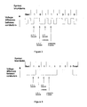
- three devices a, b and c have values to disclose: these values are 184, 168 and 136 respectively, encoded as symbol streams 10111000, 10101000 and 10001000 respectively.
- the behaviour of the devices is shown schematically in Figure 2 .
- a device that wishes to transmit a '0' will see any '1' transmission in the first half of the symbol period.
- a device that wishes to transmit a '0' and sees a ⁇ 1' transmission learns that some other device is disclosing a preferred value and therefore immediately ceases transmission.
- a , b and c all have a '1' to transmit and therefore do so.
- a , b and c all have a '0' to transmit. No other device transmits a '1' and therefore they all transmit a '0'.
- a and b have a '1' to transmit and therefore do so.
- c has a '0' to transmit, but on seeing transmission of a '1' c ceases transmission.
- a has a '1' to transmit and therefore does so.
- b has a '0' to transmit, but on seeing transmission of a '1' b ceases transmission.
- a In the fifth symbol period after the start bit, a has a '1' to transmit and therefore does so.
- a has a '0' to transmit. No other device transmits a '1' and therefore a transmits a '0'.
- This example also uses the comparator rule and the serial encoding rule for an 8-bit binary number given as examples above.
- the example uses negative logic.
- a device drives the voltage difference down during a symbol to indicate '1'; the rest of the time the voltage difference is above this level.
- the disclosure sequence preferably begins with a 1 as a start symbol, according to one of the alternatives in the previous example.
- three devices a , b and c have values to disclose: these are 184, 168 and 136 respectively, encoded as symbol streams 10111000, 10101000 and 10001000 respectively.
- the behaviour of the devices is shown schematically in Figure 3 .
- a device that wishes to transmit a '0' will see any '1' transmission throughout the symbol period.
- a device that wishes to transmit a '0' and sees a '1' transmission learns that some other device is disclosing a preferred value and therefore immediately ceases transmission.
- a , b and c all have a '1' to transmit and therefore do so.
- a , b and c all have a '0' to transmit. No other device transmits a '1' and so they remain eligible to transmit in the third symbol period.
- a and b have a '1' to transmit and therefore do so.
- c has a '0' to transmit, but on seeing transmission of a '1' c ceases transmission.
- a has a '1' to transmit and therefore does so.
- b has a '0' to transmit, but on seeing transmission of a '1' b ceases transmission.
- a In the fifth symbol period after the start bit, a has a '1' to transmit and therefore does so.
- a has a '0' to transmit. No other device transmits a '1' and therefore a remains eligible to transmit in further symbol periods.
- a Since a remains eligible to transmit after the eighth symbol period, a transmits a further '1' as a 'finish bit'.
- finish bit is to distinguish between the case where one device has a value to disclose and discloses 00000000, as against the case where no device has a value to disclose.
- each transmitter is able to recognise during a symbol period when some other transmitter has a 'superior' bit to transmit.
- a '1' is superior to a '0'.
- this invention is applicable to any arrangement of encoding on any serial line where the encoding on the line is such that each transmitter is able to recognise during a symbol period when some other transmitter has a superior bit to transmit and where a transmitter that would otherwise transmit an 'inferior' bit does not prevent other devices from detecting the transmission of the superior bit.
- search sequence for all values of IEC 62386-102 random number.
- the following example search sequence may be carried out using either of the previous encoding techniques or using any other suitable combination of symbol encoding, comparator rule and serial encoding rule. Since the IEC 62386-102 random number is an integer in the range 0 to 2 24 -1, a suitable serial encoding rule is to encode the value as a 24-bit binary number.
- a suitable comparator rule for either of the previous encoding techniques is to disclose the numerically highest value and for the encoding rule to place the most significant bit on the serial link first.
- a device wishing to learn the IEC 62386-102 random numbers held by all other devices may drive the serial link with the following sequence of messages.
- the first step may be omitted if this is the only parameter available from the devices.
- Step 4 may be omitted and Step 3 may be repeated until no device discloses a value.
- the example above is modified so that the message at Step 2 becomes 'All devices holding such a parameter shall report it no more than once, until revoked'.
- the act of disclosing a value represents an implicit instruction to the device that has disclosed the value not to disclose it again, until revoked.
- every device is able to detect and decode the symbols transmitted by all other devices.
- a device a that wishes to learn some information may detect that another device b is requesting and receiving the required information.
- device a is able to learn the information without making any disclosure requests itself.
- both device a and device b may hold one or more values of a requested parameter. In order that device b may correctly learn the complete set of values by this method, device a shall operate as a responding device with respect to the values that it holds.
- device a may have a requirement to learn up to n different values of a parameter, in a circumstance where more than n are held by the devices.
- a device b that requires to learn more than n values may observe the instructions issued by a and then issue further instructions thereafter to continue the learning sequence.
- Device b may take account of unrevoked instructions issued by a in order to minimise the instructions that it must issue.
- Device a may give an indication on the serial link that it has completed its learning sequence, thus enabling device b to continue the learning sequence, without preempting a while a is still issuing instructions.
- a device a may previously have learnt the value of a parameter held by some other device b and may wish to confirm that the value is still held.
- the parameter may be a device identifier for the device. If device a takes advantage of some functionality realised in device b , it may wish to confirm regularly whether device b is still accessible. It can do so for example by the instructions:
- a parameter may be held by different devices using a varying numbers of bits.
- the unique numbers assigned to lighting control equipment as specified in IEC 62386-102 may vary at the choice of individual manufacturer from 96 to 128 bits in length.
- Parameters held by different devices using a varying numbers of bits may be disclosed by padding the shorter representations by inserting patterns of 1 or 0 bits at defined points within the disclosure, such that all patterns are the same length.
- the difference in parameter length may be related to a substructure within the parameter. For example one device has a parameter value containing sub-fields a , b and c while another device has a parameter value containing sub-fields a and c .
- one or more bit patterns may be inserted into the messages to indicate the presence or length of optional sub-sequences within the overall bit pattern.
- the presence or length indicators are inserted before the sub-sequences to which they relate.
- a bit sequence that may vary between 1 and 256 bits in length is delivered with an 8-bit pattern placed at its head that indicates the number of bits following in the sequence. This added pattern both provides a comparator between messages of different lengths and also enables messages of any permitted length to be disclosed and interpreted correctly.
- bitwise comparator rule and the variable length encoding techniques described above allow any bit sequence held by any device to be disclosed.
- the way in which the bit sequence is used to encode a value can in general be arranged to allow for values to be disclosed in a desired order.
- "floating point" or non-integer numbers are generally represented by a sign bit, a set of bits for a mantissa and a set of bits for an exponent.
- the sign bit should be presented first, followed by the exponent and then the mantissa. Where the number is negative, the exponent and mantissa values should be presented with each bit inverted (1 in place of 0 and 0 in place of 1).
- mantissa and exponent should be encoded such that any changes in exponent are always more significant in multiplicative effect than any changes in mantissa.
- the same encoding rule should be used with a bitwise comparator rule to prefer a '0' to a ⁇ 1' at each symbol transmission.
- bit inversion can be employed in general to make a comparator function suited to the symbol encoding on a particular serial line.
- the preferred embodiments of the present invention relate to any case where one or more devices have one or more values of a parameter to disclose.
- the parameter to be disclosed may be a compound value consisting of two or more elements, for example a temperature and a pressure measured by a device. Any compound value that can be represented as a single sequence of bits can be disclosed in the same manner as a single value.
- the preferred embodiments of the present invention are applicable to cases where only the set of values of the parameter are of interest, not the identity of the devices holding them nor the number of devices holding the same value.
- a number of devices may have measured a temperature. It may be desired to determine the range of temperatures that have been measured by the devices. In such a case, all different temperatures are disclosed; two or more devices with the same value to disclose will disclose them at the same time, since none of these devices will detect a "superior" disclosure during their own disclosures.
- the preferred embodiments of the present invention are applicable to cases where the set of values of the parameter and the number of devices holding the same value are of interest, but not the identity of the devices holding them.
- a number of devices may have measured a temperature. It may be desired to determine the average temperature measured by the devices.
- each disclosure may be a compound value consisting of the temperature and some "tie breaker" such as a unique number held by exactly one disclosing device. This allows every temperature measurement to be disclosed exactly once.
- the preferred embodiments of the present invention are applicable to cases where the set of values of the parameter and the identity of the devices holding them are both of interest.
- a compound value consisting of the parameter value and a unique number held by exactly one disclosing device would be disclosed in such a case.
- the existing technique commonly used for searching for parameter values over a communications line is set out in IEC 62386-102, where it is described with reference to a search for 24-bit random numbers, each device holding one such number.
- the existing technique makes use of a "comparator register", i.e. a 24-bit value that is transmitted to all other devices by the device that requires the disclosure.
- the messages that are used are:
- the symbol encoding rate is 1200 symbols per second.
- a single disclosure using the technique and encoding rules described in IEC 62386-102 takes at least 2 seconds.
- Techniques according to the preferred embodiments of the present invention can generate a disclosure of a 24-bit value in 50ms using a symbol encoding rate of 1200 symbols per second. Since systems implemented in compliance with IEC 62386-102 may have 128 devices attached to a serial link, the time taken for a complete search is over 4 minutes according to IEC 62386-102 or around 6 seconds according to the preferred embodiments of the present invention.
- the preferred embodiments of the present invention may readily be incorporated as an enhancement to IEC 62386-102 in such a way as to provide an enhancement to those devices that incorporate this invention but so as not to affect the behaviour of a lighting device built in conformance to IEC 62386-102 but not incorporating this invention.
- One way to achieve this is to use two of the command codes designated in IEC 62386-102 as "Reserved for future needs.
- the control gear shall not react in any way" to signal Step 3 and Step 4 as defined above.
- the command code used to signal Step 4 or an additional command code may also be used to indicate to a device that it should not take part in the search procedure currently defined in IEC 62386-102.
- a start bit for the response to Step 3 may be generated by the device that signalled Step 3, for example in the form of 1 bit signalled a defined time after the signal for Step 3.
- a combination of this bit plus either no response or 24 bits in response from a disclosing device will be ignored by a lighting device built in conformance to IEC 62386-102 but not incorporating this invention.
- any transmission of between 1 and 34 bits, other than a sequence of 16 bits, will be ignored by a lighting device built in conformance to IEC 62386-102 but not incorporating this invention.
- any disclosure of between 1 and 33 bits in length can be made by the method above, using more than one start bit in the case of a 15-bit disclosure.
- the disclosure may proceed by means of the device that signalled Step 3 repeatedly generating one or more start bits, eliciting a response of up to 33 bits on each repetition of the start bit(s), until either no value or a full parameter value has been disclosed.
- the number of start bits may be adjusted on each repetition such as to ensure that each repetition will be ignored by a lighting device built in conformance to IEC 62386-102 but not incorporating this invention. It may be noted that at the present time, lighting devices built in conformance to IEC 62386-102 typically incorporate a computing device suitable to implement the processing steps shown in Figure 2 , at the IEC 62386-102 symbol encoding rate.
- a search to detect the continued presence or disappearance of previously identified IEC 62386-102 devices can be accomplished using techniques according to IEC 62386-102, but only slowly. According to the preferred embodiments of the present invention, detection of the presence of previously identified devices and/or previously unidentified devices can be carried out significantly more quickly.
- the parameter disclosed is a compound value consisting of the random number plus the short address, where the short address encoding allows a value "not assigned a short address" to be encoded in place of a short address value; this compound value can be encoded using 31 bits.
- all of the devices in the system can both interrogate other devices, by transmitting requests for other devices to disclose values of parameters held by the devices, and respond to such requests.
- Examples of use of this invention have been given relating to systems distributed around a building, in particular discrete devices distributed around a building.
- the invention may be applied to systems of greater size and to systems of smaller size.
- the devices comprising the system may be very far apart and linked using very long distance telemetry links.
- One suitable realisation of the serial link in this case would be low frequency radio transmission with symbol encoding rate long enough for all devices in the system to detect other transmissions within a symbol encoding period.
- the devices comprising the system may be located on a single electronic circuit board or within a single electronic device. Suitable realisations of the serial link in this case include electrical conductive paths or various electromagnetic means of signalling between the devices.
- inventions described herein principally comprise computer processes performed in computer apparatus and computer apparatus per se, in combination with other electrical or electronic apparatus
- the invention also extends to computer programs, particularly computer programs on or in a carrier, adapted for putting the invention into practice.
- the program may be in the form of source code, object code, a code intermediate source or object code such as in a partially compiled form, or in any other form suitable for use in implementation of the processes according to the invention.
- the carrier may be any entity or device capable of carrying the program.
- the carrier may comprise a storage medium, such as a ROM, for example a CD ROM or a semiconductor ROM, or a magnetic recording medium, for example a hard disk.
Description
- The present invention relates to a method of and apparatus for searching for values of one or more parameters held by one or more of a plurality of devices and also relates to a device capable of storing a value of a parameter and disclosing the value on request.
- In many systems, serial links are used to connect devices together. Examples of such systems include those used to control and monitor the operation of a building, for example the lighting, air conditioning, fire detection or security mechanisms within a building. Devices in such a system might include actuators that turn individual lights or heaters on and off, sensors that detect ambient light or temperature levels or the presence of people within an area in the building, and computing engines that process the information from sensors to determine the desired settings of actuators. A serial link is a means of exchanging data between two or more devices, a single symbol at a time. A common embodiment of a serial link is a pair of electrical conductors, the voltage difference between which is used to encode binary symbols (commonly referred to as '1' and '0'). Common methods for encoding binary symbols on a serial link include 'non return to zero' and 'Manchester code', examples of which are shown schematically in
Figure 1 . In such an embodiment, all devices are normally aware of the signalling period, that is to say the time taken to encode a binary symbol on the serial link. This may be known a priori or one device may learn the signalling period for example by decoding a transmission by another device. - In the case of non return to zero encoding, one of two voltage differences is maintained for a complete signalling period, to indicate a '1' or '0'. The example shown in
Figure 1 is commonly described as 'Negative Logic', since a '1' is represented by the lower of two voltage differences. In the case of Manchester Code, a change of voltage difference occurs at the midpoint of each signalling period; the direction of that change in difference indicates a '1' or '0'. Serial links may operate in a synchronous manner, that is to say where at least one device is driving the link ("transmitting") at any time, generating symbols in such a way as to maintain a regular signalling interval. Serial links may also operate in an asynchronous manner, in which the link is not driven all the time. Such a case is shown inFigure 1 for Manchester code. When the link is not driven, there are no significant changes of voltage level; the start of transmission is marked by a significant change of voltage level. Serial links may operate with a "bias", that is to say that the link is normally held at one voltage level by one or more devices or some other equipment attached to the link; the biasing circuit is such that a device that requires to drive the link to one of the voltage levels indicating '1' or '0' will succeed in doing so in preference to the bias. Where the bias is one of the voltage levels indicating '1' or '0', a device that requires to drive the link to one of the voltage levels does so only when the other voltage level is required. - Other common embodiments of a serial link include wireless links, for example radio links. For example, both of the symbol encodings shown in
Figure 1 can be conveyed over the medium of radio by replacing the lower voltage difference level by emission of a radio signal and the higher voltage difference level by no such emission. It will be understood that many different radio modulation and signalling techniques are known; an example of a suitable technique would be for each device to emit a continuous carrier frequency as a replacement for the lower voltage difference level, the carrier frequency used by each device being slightly different in order to avoid anti-phase cancellation at any receiving device. - In an arrangement where two or more devices are connected using a serial link, a need often arises for one such device to learn the values of a parameter held by one or more other devices. Such a parameter value will typically be held by a device as a single value from a discrete set of possible values. In some cases, the parameter will be a sparse parameter, that is to say a parameter that may take one of a very large number of values, and where significantly fewer instances of such values are held by the devices. Some commonly encountered examples of sparse parameters are "MAC address" numbers specified in ISO 8802.1 for identification of computer communication devices. These are taken from a range of 248 different numbers, while a typical system may incorporate from two to a few hundred devices. The number space specified in ISO 16484-5 for assigning a unique identifier to a device is a range of 222 different numbers and ISO 16484-5 also further defines a MAC address number per device in a range of up to 248 different numbers. The number space specified in IEC 62386-102 for assigning unique numbers to lighting control devices is a range of up to 2128 different numbers. Also under IEC 62386-102 a lighting control device may be instructed to pick and retain a random number from a range of 224 different numbers. These are all examples of sparse parameters: in these particular cases, each device holds only one such value and significantly fewer devices are present on the serial link than the set of possible values.
-
US5968154 discloses a method of arbitrating between a number of devices which are attempting to access a serial data bus. -
US2004-0217718A1 discloses a digitally addressable electronic ballast and control unit. An address search technique according to a DALI (Digital Addressable Lighting Interface) standard is described. - According to a first aspect of the present invention, there is provided a method of learning values of one or more parameters held by a plurality of devices that are capable of communication with each other via a serial communications link, the method comprising:
- (A) one of said devices issuing a request over the serial communications link for said devices to disclose over the serial communications link a value of a parameter held by the devices; and,
- (B) in response thereto, each of the devices that hold such a value and that have been requested to disclose the value attempting to disclose the value held by the device, while monitoring for attempts by other devices to disclose values held by the other devices, the devices being arranged so that at most one value is disclosed in response to each request; and
repeating (A) and (B) such that a plurality of said devices that hold such a value and that have been requested to disclose the value have disclosed the value such that said requesting device learns the values of the parameter held by said plurality of devices. - In a preferred embodiment, one or more devices are connected together using a serial link. Each device is able to transmit on the serial link at times of its own choosing; furthermore, each device is able to detect the resultant signals due to one or more devices transmitting on the serial link at times of their own choosing. The effect resulting in a case where more than one device transmits on the serial link at the same time is known by all devices, as is the effect resulting in a case where no device transmits on the serial link. As a result, at most one value is disclosed in response to each request. This can be achieved very quickly compared to corresponding prior art techniques of learning the values of parameters held,by devices.
- In general, for any given parameter, each device may hold zero, one or more instances of values of that parameter. One or more devices can learn the parameter values held by one or more devices connected using the serial link.
- In an embodiment, each device operates a comparator rule whereby if a device learns that another of the devices is transmitting a value that is preferred to the value that is being transmitted by said device, then said device ceases transmitting its value. A "preferred" value may for example be one that is greater than the value held by the device concerned.
- In an embodiment, each device operates a comparator rule whereby if a device holds plural values for a parameter, the device transmits a preferred one of said values in response to the request. A "preferred" value may be for example one that is the greatest of the values held by the device concerned. This enables a particularly efficient and therefore rapid transmission scheme, by which all devices disclose their relevant values, to be achieved.
- In an embodiment, the request for said devices to disclose a parameter held by the devices includes or is accompanied by a restriction on the devices that are to respond to said request such that only a subset of the devices respond to said request.
- In an embodiment, the values held by the devices may be represented by a number of bits that varies between the devices, and wherein the devices insert bits into the values transmitted by the devices such that the bit values that are transmitted by the devices are all of the same length.
- In an embodiment, the values held by the devices may be represented by a number of bits that varies between the devices, and wherein the devices insert one or more bit patterns into the values transmitted by the devices to indicate the presence or length of optional sub-sequences within the overall bit pattern transmitted by the devices.
- In general, these embodiments provide a simple way of allowing any bit sequence held by any device to be disclosed in a way that can be understood by other devices.
- In an embodiment, the value is encoded as a binary number, the most significant bit being placed on the serial link first.
- In an embodiment, each device is able to recognise during a symbol period when some other device has a superior bit to transmit and a device that would otherwise transmit an inferior bit does not prevent other devices from detecting the transmission of the superior bit. Again, this enables a particularly efficient and therefore rapid transmission scheme, by which all devices disclose their relevant values, to be achieved.
- In an embodiment, the devices employ "Manchester Coding" bit encoding. As an alternative, the devices employ "non return to zero" bit encoding.
- In an embodiment, a parameter to be disclosed is an IEC 62386-102 random number. In an alternative, a parameter to be disclosed is a compound value consisting of plural elements. As another alternative, a parameter to be disclosed is a compound value consisting of an IEC 62386-102 random number and an IEC 62386-102 short address.
- In an embodiment, the devices are discrete devices distributed around a building. Such devices may be for example for controlling and monitoring the operation of a building, for example the lighting, air conditioning, fire detection or security mechanisms within a building. Devices in such a system might include actuators that turn individual lights or heaters on and off, sensors that detect ambient light or temperature levels or the presence of people within an area in the building, and computing engines that process the information from sensors to determine the desired settings of actuators.
- According to a second aspect of the present invention, there is provided a device arranged to learn values of one or more parameters held by a plurality of devices that are capable of communication with each other via a serial communications link, the device being arranged to:
- issue a request over the serial communications link for said plurality of devices to disclose over the serial communications link a value of a parameter held by said plurality of devices, wherein in response thereto each of said devices that hold such a value and that have been requested to disclose the value attempt to disclose the value held by the device while monitoring for attempts by other devices to disclose values held by the other devices, said plurality of devices being arranged so that at most one value is disclosed in response to each request; and
- repeat the issuing of the request such that a plurality of said plurality of devices that hold such a value and that have been requested to disclose the value have disclosed the value;
- such that said device learns the values of the parameter held by a plurality of said devices.
- In an embodiment, a parameter to be disclosed is one of an IEC 62386-102 random number, a compound value consisting of plural elements, and a compound value consisting of an IEC 62386-102 random number and an IEC 62386-102 short address.
- In an embodiment, the device is arranged such that the request for devices to disclose a parameter held by the devices includes or is accompanied by a restriction on the devices that are to respond to said request such that only a subset of the devices respond to said request.
- According to a third aspect of the present invention, there is provided apparatus comprising a plurality of discrete devices that are distributed around a building and capable of communication with each other via a serial communications link, wherein the devices are arranged such that:
- at least one of said devices is able to issue a request over the serial communications link for said devices to disclose over the serial communications link a value of a parameter held by the devices; and,
- in response thereto, each of the devices that hold such a value and that have been requested to disclose the value attempts to disclose the value held by the device, while monitoring for attempts by other devices to disclose values held by the other devices, the devices being arranged so that at most one value is disclosed in response to each request;
- said at least one of said devices being arranged to repeat said request over the serial communications link for said devices to disclose over the serial communications link a value of a parameter held by the devices such that a plurality of said devices that hold such a value and that have been requested to disclose the value have disclosed the value;
- thereby enabling one or more of the devices to learn the values of the parameter held by a plurality of the devices.
- Embodiments of the present invention will now be described by way of example with reference to the accompanying drawings, in which:
-
Figure 1 shows schematically the encoding of binary symbols on a serial link using 'non return to zero' and 'Manchester code' encoding; -
Figure 2 shows schematically signal transmission on a communications link during operation of an embodiment of the present invention using Manchester code; and, -
Figure 3 shows schematically signal transmission on a communications link during operation of an embodiment of the present invention using non return to zero code. - In an embodiment of the present invention, plural devices communicate with each other via a serial communications link, which in general may be wired or wireless. The devices may be discrete devices, which may be distributed around a building for example. Examples of systems using such an arrangement include those used to control and monitor the operation of a building, for example the lighting, air conditioning, fire detection or security mechanisms within a building. Devices in such a system might include actuators that turn individual lights or heaters on and off, sensors that detect ambient light or temperature levels or the presence of people within an area in the building, and computing engines that process the information from sensors to determine the desired settings of actuators. As a particular example, fluorescent lights typically employ a digital ballast, which can apply quite complex logic to lamp starting and operation and enable functions such as testing for broken electrodes and missing tubes before attempting to start and auto-detection of tube replacement and tube type. They allow features such as dimming and having the ballast maintain a constant light level against changing ambient light contribution to be easily included in the embedded microcontroller software.
- In operation, one device transmits on the serial link a sequence of symbols that indicate or relate to an instruction for certain or all of the devices to disclose a value that they hold for a parameter. The transmission may include any or all of the following information:
- the instruction to disclose a value;
- information identifying the parameter whose value is to be disclosed. This is applicable where there is more than one different parameter whose value can be disclosed by a device;
- the number of symbols to be used by the disclosing device(s) to encode the parameter. This is useful in the case that different devices hold values for the same parameter that are selected from a different range of discrete values. Optionally the request may require only those values that can be encoded in the specified number of symbols to be disclosed;
- a restriction on the devices that should report the values that they hold. Using the examples given above, an IEC 62386-102 lighting control device might be requested to report its random number only if that random number lies in a specified range of numbers or if its unique number lies in a specified range of numbers. The restriction may also be expressed in negative terms. For example a device might be requested to report a parameter value only if the value does not lie in a specified range of numbers.
- An instruction to disclose a value may incorporate other information in the list above. Alternatively the instruction may be preceded by other information in the list, transmitted in one or more separate sequences of symbols. The applicability of information transmitted as separate sequences of symbols may vary. For example it may be indicated as applying to the next disclosure instruction, to all further disclosure instructions until revoked or for some defined number of following disclosure instructions.
- As a specific example, a device wishing to learn the IEC 62386-102 random numbers held by all other devices may transmit the following sequence of messages on the serial link:
- Parameter required is IEC 62386-102 random number, until revoked
- All devices holding such a parameter shall report it, until revoked
- Disclose a value - whereupon one device discloses value x
- Device holding the value x shall not report it, until revoked
- Disclose a value - whereupon one device discloses value y
- Device holding the value y shall not report it, until revoked
- In this example, each directive that applies until revoked is defined to modify but not to revoke any previous conflicting directives. Hence at the end of the sequence above, all devices holding an IEC 62386-102 random number whose value is neither x nor y would be entitled to disclose it.
- Upon receiving an instruction to disclose a value, each device first determines whether it has at least one value that it is entitled to disclose, taking into account any stipulations in and preceding the disclosure instruction. In one embodiment, if the device has at least one such value, it uses the following procedure to ensure that no more than one such value is disclosed on the serial link at one time.
- For each parameter, the device holds a comparator rule and a serial encoding rule. As examples, for a parameter whose possible range of discrete values are integers in the
range 0 to 28-1, a device may hold a comparator rule which is to disclose the numerically highest value and a serial encoding rule which is to encode the value as an 8-bit binary number, the most significant bit being placed on the serial link first. (As a simple alternative, a device may hold a serial encoding rule which is to encode the value as an 8-bit binary number, the least significant bit being placed on the serial link first, and a comparator rule which is to disclose its value only if there is no bit position at which the device would disclose a '1' and at which some other device would disclose a '0'.) - If the device holds more than one value that it is entitled to disclose, it first uses the comparator rule to select one such value. The device then begins to drive the line with symbols as defined by the encoding rule. As it drives the line, it also monitors for other devices driving the line and thus learns whether any other device is disclosing a value that is preferred, according to the comparator rule, to the value that it is attempting to disclose.
- In the event that the device learns that another device is disclosing a value that is preferred according to the comparator rule, the device immediately stops its own disclosure. Otherwise it continues until the value is fully disclosed.
- There now follows a specific example of disclosure and comparison by the devices using Manchester Coding. This example uses the comparator rule and the serial encoding rule for an 8-bit binary number given as examples above and uses the style of Manchester encoding shown in
Figure 1 . A device drives the voltage difference down in the first half of a symbol to indicate '1'; it drives the voltage difference down in the second half of a symbol to indicate '0'. - The disclosure sequence preferably begins with a 'start symbol'. This is a symbol that immediately precedes disclosure of the first symbol of the requested value. The start symbol may be the last symbol of the disclosure instruction message. Alternatively the requesting device may transmit a set of one or more symbols some time after the disclosure instruction message, the last symbol of which serves as the start symbol. Alternatively each device holding at least one value that it is entitled to disclose may be entitled to transmit the start symbol within a specified time window following the disclosure request message. In the case of this last alternative, one or more devices may transmit the start symbol before some others attempt to so do and all other devices that are entitled to disclose a value will detect this transmission as the start symbol. In an alternative embodiment, the start bit is not present; the devices begin their disclosures some measured time after some previous transmission on the link.
- In the following example, three devices a, b and c have values to disclose: these values are 184, 168 and 136 respectively, encoded as symbol streams 10111000, 10101000 and 10001000 respectively. The behaviour of the devices is shown schematically in
Figure 2 . - In any symbol period, a device that wishes to transmit a '0' will see any '1' transmission in the first half of the symbol period. According to the comparator rule, a device that wishes to transmit a '0' and sees a `1' transmission learns that some other device is disclosing a preferred value and therefore immediately ceases transmission.
- In the first symbol period after the start bit, a, b and c all have a '1' to transmit and therefore do so.
- In the second symbol period after the start bit, a, b and c all have a '0' to transmit. No other device transmits a '1' and therefore they all transmit a '0'.
- In the third symbol period after the start bit, a and b have a '1' to transmit and therefore do so. c has a '0' to transmit, but on seeing transmission of a '1' c ceases transmission.
- In the fourth symbol period after the start bit, a has a '1' to transmit and therefore does so. b has a '0' to transmit, but on seeing transmission of a '1' b ceases transmission.
- In the fifth symbol period after the start bit, a has a '1' to transmit and therefore does so.
- In the sixth to eighth symbol periods after the start bit, a has a '0' to transmit. No other device transmits a '1' and therefore a transmits a '0'.
- It will be noted that in the event that no device has a value to disclose, no transmissions will occur in the symbol period after the start bit.
- There now follows a second specific example of disclosure and comparison by the devices using non return to zero encoding. This example also uses the comparator rule and the serial encoding rule for an 8-bit binary number given as examples above. The example uses negative logic. A device drives the voltage difference down during a symbol to indicate '1'; the rest of the time the voltage difference is above this level.
- The disclosure sequence preferably begins with a 1 as a start symbol, according to one of the alternatives in the previous example. Again, in this example, three devices a, b and c have values to disclose: these are 184, 168 and 136 respectively, encoded as symbol streams 10111000, 10101000 and 10001000 respectively. The behaviour of the devices is shown schematically in
Figure 3 . - In any symbol period, a device that wishes to transmit a '0' will see any '1' transmission throughout the symbol period. According to the comparator rule, a device that wishes to transmit a '0' and sees a '1' transmission learns that some other device is disclosing a preferred value and therefore immediately ceases transmission.
- In the first symbol period after the start bit, a, b and c all have a '1' to transmit and therefore do so.
- In the second symbol period after the start bit, a, b and c all have a '0' to transmit. No other device transmits a '1' and so they remain eligible to transmit in the third symbol period.
- In the third symbol period after the start bit, a and b have a '1' to transmit and therefore do so. c has a '0' to transmit, but on seeing transmission of a '1' c ceases transmission.
- In the fourth symbol period after the start bit, a has a '1' to transmit and therefore does so. b has a '0' to transmit, but on seeing transmission of a '1' b ceases transmission.
- In the fifth symbol period after the start bit, a has a '1' to transmit and therefore does so.
- In the sixth to eighth symbol periods after the start bit, a has a '0' to transmit. No other device transmits a '1' and therefore a remains eligible to transmit in further symbol periods.
- Since a remains eligible to transmit after the eighth symbol period, a transmits a further '1' as a 'finish bit'.
- The purpose of the finish bit is to distinguish between the case where one device has a value to disclose and discloses 00000000, as against the case where no device has a value to disclose.
- In both the encoding schemes above, each transmitter is able to recognise during a symbol period when some other transmitter has a 'superior' bit to transmit. In the examples above, a '1' is superior to a '0'. In general, this invention is applicable to any arrangement of encoding on any serial line where the encoding on the line is such that each transmitter is able to recognise during a symbol period when some other transmitter has a superior bit to transmit and where a transmitter that would otherwise transmit an 'inferior' bit does not prevent other devices from detecting the transmission of the superior bit.
- There now follows a specific example of a search sequence for all values of IEC 62386-102 random number. The following example search sequence may be carried out using either of the previous encoding techniques or using any other suitable combination of symbol encoding, comparator rule and serial encoding rule. Since the IEC 62386-102 random number is an integer in the
range 0 to 224-1, a suitable serial encoding rule is to encode the value as a 24-bit binary number. A suitable comparator rule for either of the previous encoding techniques is to disclose the numerically highest value and for the encoding rule to place the most significant bit on the serial link first. - A device wishing to learn the IEC 62386-102 random numbers held by all other devices may drive the serial link with the following sequence of messages. The first step may be omitted if this is the only parameter available from the devices.
- Step 1: Message is 'Parameter required is IEC 62386-102 random number, until revoked'
- Step 2: Message is 'All devices holding such a parameter shall report it, until revoked'
- Step 3: Message is 'Disclose a value'
- If no device discloses a value at Step 3, all such values have been learnt. Otherwise proceed to Step 4.
- Step 4: Message is 'Device holding the value most recently reported at Step 3 shall not report it, until revoked'
- Repeat from Step 3.
- Note that the message at Step 4 may refer implicitly or explicitly to the value that was disclosed at Step 3.
- As an alternative to making an implicit reference at Step 4, Step 4 may be omitted and Step 3 may be repeated until no device discloses a value. In this alternative case, the example above is modified so that the message at Step 2 becomes 'All devices holding such a parameter shall report it no more than once, until revoked'. The act of disclosing a value represents an implicit instruction to the device that has disclosed the value not to disclose it again, until revoked.
- In general, as the devices are connected to each other via a communications link, every device is able to detect and decode the symbols transmitted by all other devices. As a result, a device a that wishes to learn some information may detect that another device b is requesting and receiving the required information. By decoding the symbols transmitted by all devices, device a is able to learn the information without making any disclosure requests itself. In general, both device a and device b may hold one or more values of a requested parameter. In order that device b may correctly learn the complete set of values by this method, device a shall operate as a responding device with respect to the values that it holds.
- It may be that device a has a requirement to learn up to n different values of a parameter, in a circumstance where more than n are held by the devices. In such a case, a device b that requires to learn more than n values may observe the instructions issued by a and then issue further instructions thereafter to continue the learning sequence. Device b may take account of unrevoked instructions issued by a in order to minimise the instructions that it must issue. Device a may give an indication on the serial link that it has completed its learning sequence, thus enabling device b to continue the learning sequence, without preempting a while a is still issuing instructions.
- As an example of an instruction applying only to the next disclosure instruction, a device a may previously have learnt the value of a parameter held by some other device b and may wish to confirm that the value is still held. For example the parameter may be a device identifier for the device. If device a takes advantage of some functionality realised in device b, it may wish to confirm regularly whether device b is still accessible. It can do so for example by the instructions:
- Only the device holding device identifier parameter with value [b's identifier] shall respond to the next disclosure instruction
- Parameter required is device identifier; disclose a value.
- There now follow examples of other comparator rules and serial encoding rules. In the example rules given above, a search will result in values being disclosed in descending order of value. More generally, the techniques described above can be applied to any value which can be represented as a fixed number of bits, irrespective of the interpretation of each bit. The comparator functions described above operate in a bitwise manner, so that in general they constitute a rule to prefer a '1' to a '0' at each symbol transmission. Thus, each different value represented as a bit pattern will be found if steps 3 and 4 are repeated until no more values are disclosed.
- In some situations, a parameter may be held by different devices using a varying numbers of bits. For example the unique numbers assigned to lighting control equipment as specified in IEC 62386-102 may vary at the choice of individual manufacturer from 96 to 128 bits in length. Parameters held by different devices using a varying numbers of bits may be disclosed by padding the shorter representations by inserting patterns of 1 or 0 bits at defined points within the disclosure, such that all patterns are the same length. In some cases, the difference in parameter length may be related to a substructure within the parameter. For example one device has a parameter value containing sub-fields a, b and c while another device has a parameter value containing sub-fields a and c. In such a case, one or more bit patterns may be inserted into the messages to indicate the presence or length of optional sub-sequences within the overall bit pattern. Preferably the presence or length indicators are inserted before the sub-sequences to which they relate. In this case, it is not in general necessary for each disclosed message to be the same length. As an example, suppose that a bit sequence that may vary between 1 and 256 bits in length is delivered with an 8-bit pattern placed at its head that indicates the number of bits following in the sequence. This added pattern both provides a comparator between messages of different lengths and also enables messages of any permitted length to be disclosed and interpreted correctly.
- It will be understood that the bitwise comparator rule and the variable length encoding techniques described above allow any bit sequence held by any device to be disclosed. The way in which the bit sequence is used to encode a value can in general be arranged to allow for values to be disclosed in a desired order. For example "floating point" or non-integer numbers are generally represented by a sign bit, a set of bits for a mantissa and a set of bits for an exponent. To allow such numbers to be disclosed in descending order, the sign bit should be presented first, followed by the exponent and then the mantissa. Where the number is negative, the exponent and mantissa values should be presented with each bit inverted (1 in place of 0 and 0 in place of 1). Furthermore, the mantissa and exponent should be encoded such that any changes in exponent are always more significant in multiplicative effect than any changes in mantissa. To allow such numbers to be disclosed in ascending order, the same encoding rule should be used with a bitwise comparator rule to prefer a '0' to a `1' at each symbol transmission.
- It will also be understood that bit inversion can be employed in general to make a comparator function suited to the symbol encoding on a particular serial line.
- In general, the preferred embodiments of the present invention relate to any case where one or more devices have one or more values of a parameter to disclose.
- The parameter to be disclosed may be a compound value consisting of two or more elements, for example a temperature and a pressure measured by a device. Any compound value that can be represented as a single sequence of bits can be disclosed in the same manner as a single value.
- The preferred embodiments of the present invention are applicable to cases where only the set of values of the parameter are of interest, not the identity of the devices holding them nor the number of devices holding the same value. For example, a number of devices may have measured a temperature. It may be desired to determine the range of temperatures that have been measured by the devices. In such a case, all different temperatures are disclosed; two or more devices with the same value to disclose will disclose them at the same time, since none of these devices will detect a "superior" disclosure during their own disclosures.
- The preferred embodiments of the present invention are applicable to cases where the set of values of the parameter and the number of devices holding the same value are of interest, but not the identity of the devices holding them. Again for example, a number of devices may have measured a temperature. It may be desired to determine the average temperature measured by the devices. In such a case, each disclosure may be a compound value consisting of the temperature and some "tie breaker" such as a unique number held by exactly one disclosing device. This allows every temperature measurement to be disclosed exactly once.
- The preferred embodiments of the present invention are applicable to cases where the set of values of the parameter and the identity of the devices holding them are both of interest. A compound value consisting of the parameter value and a unique number held by exactly one disclosing device would be disclosed in such a case.
- As an indication of the advantages of the preferred embodiments of the present invention, the existing technique commonly used for searching for parameter values over a communications line is set out in IEC 62386-102, where it is described with reference to a search for 24-bit random numbers, each device holding one such number. The existing technique makes use of a "comparator register", i.e. a 24-bit value that is transmitted to all other devices by the device that requires the disclosure. The messages that are used are:
- All devices shall take part in the search procedure
- Here is a new value of comparator register
- Any device still taking part in the search whose random number value is less than or equal to the comparator register shall respond by transmitting a defined symbol pattern
- The device whose random number value equals the comparator register shall cease to take part in the search procedure.
- By using these messages, 24 variations on the comparator register are set and 24 requests for response are used in order to obtain one random number value from one device. That device then ceases to take part in the search procedure and further set/request messages are used, up to 24 set/requests per further random number value obtained from a device, until all values are disclosed.
- In the case of IEC 62386-102, the symbol encoding rate is 1200 symbols per second. A single disclosure using the technique and encoding rules described in IEC 62386-102 takes at least 2 seconds. Techniques according to the preferred embodiments of the present invention can generate a disclosure of a 24-bit value in 50ms using a symbol encoding rate of 1200 symbols per second. Since systems implemented in compliance with IEC 62386-102 may have 128 devices attached to a serial link, the time taken for a complete search is over 4 minutes according to IEC 62386-102 or around 6 seconds according to the preferred embodiments of the present invention.
- The preferred embodiments of the present invention may readily be incorporated as an enhancement to IEC 62386-102 in such a way as to provide an enhancement to those devices that incorporate this invention but so as not to affect the behaviour of a lighting device built in conformance to IEC 62386-102 but not incorporating this invention. One way to achieve this is to use two of the command codes designated in IEC 62386-102 as "Reserved for future needs. The control gear shall not react in any way" to signal Step 3 and Step 4 as defined above. The command code used to signal Step 4 or an additional command code may also be used to indicate to a device that it should not take part in the search procedure currently defined in IEC 62386-102. Where there are plural devices, of which only some incorporate the present invention, this permits disclosure of random addresses by all devices, each disclosure in the most efficient manner supported by the device in question. A start bit for the response to Step 3 may be generated by the device that signalled Step 3, for example in the form of 1 bit signalled a defined time after the signal for Step 3. A combination of this bit plus either no response or 24 bits in response from a disclosing device will be ignored by a lighting device built in conformance to IEC 62386-102 but not incorporating this invention.
- More generally, any transmission of between 1 and 34 bits, other than a sequence of 16 bits, will be ignored by a lighting device built in conformance to IEC 62386-102 but not incorporating this invention. Hence any disclosure of between 1 and 33 bits in length can be made by the method above, using more than one start bit in the case of a 15-bit disclosure. In the case where a longer disclosure is required, for example of the unique number of a lighting control device comprising up to 128 bits, the disclosure may proceed by means of the device that signalled Step 3 repeatedly generating one or more start bits, eliciting a response of up to 33 bits on each repetition of the start bit(s), until either no value or a full parameter value has been disclosed. The number of start bits may be adjusted on each repetition such as to ensure that each repetition will be ignored by a lighting device built in conformance to IEC 62386-102 but not incorporating this invention. It may be noted that at the present time, lighting devices built in conformance to IEC 62386-102 typically incorporate a computing device suitable to implement the processing steps shown in
Figure 2 , at the IEC 62386-102 symbol encoding rate. - In the case of IEC 62386-102, a search for 24-bit random numbers is used as a means to identify devices not previously detected on the serial link. Each device that is identified is then assigned a "short address" unique to that device on that serial link; thereafter, the short address is used to communicate with that device.
- In systems containing IEC 62386-102 devices, a need often arises to detect both previously unidentified devices and the disappearance of previously identified devices. For example, this permits the case of removal of a failed device and insertion of a replacement device to be detected and also allows the replacement device to be assigned the short address previously assigned to the failed device. Just as in the case of a search for new random numbers, a search to detect the continued presence or disappearance of previously identified IEC 62386-102 devices can be accomplished using techniques according to IEC 62386-102, but only slowly. According to the preferred embodiments of the present invention, detection of the presence of previously identified devices and/or previously unidentified devices can be carried out significantly more quickly. The parameter disclosed is a compound value consisting of the random number plus the short address, where the short address encoding allows a value "not assigned a short address" to be encoded in place of a short address value; this compound value can be encoded using 31 bits.
- It will be understood that the relative savings in search time produced by the preferred embodiments of the present invention will be the greater as the number of bits used to encode the value being disclosed increases. The benefits in general will be the greater the sparser the values are. Nevertheless, this invention may be applied to searching for parameter values of any encoding length, interpretation or degree of sparseness.
- It may be that all of the devices in the system can both interrogate other devices, by transmitting requests for other devices to disclose values of parameters held by the devices, and respond to such requests. On the other hand, it may be that only one device or only some of the devices in the system can interrogate other devices (and may or may not be configured to respond to such requests), whereas all of the other devices are not capable of issuing such requests and instead only respond to such requests.
- Examples of use of this invention have been given relating to systems distributed around a building, in particular discrete devices distributed around a building. However, the invention may be applied to systems of greater size and to systems of smaller size. For example, the devices comprising the system may be very far apart and linked using very long distance telemetry links. One suitable realisation of the serial link in this case would be low frequency radio transmission with symbol encoding rate long enough for all devices in the system to detect other transmissions within a symbol encoding period. In another example, the devices comprising the system may be located on a single electronic circuit board or within a single electronic device. Suitable realisations of the serial link in this case include electrical conductive paths or various electromagnetic means of signalling between the devices.
- Although embodiments of the invention described herein principally comprise computer processes performed in computer apparatus and computer apparatus per se, in combination with other electrical or electronic apparatus, the invention also extends to computer programs, particularly computer programs on or in a carrier, adapted for putting the invention into practice. The program may be in the form of source code, object code, a code intermediate source or object code such as in a partially compiled form, or in any other form suitable for use in implementation of the processes according to the invention. The carrier may be any entity or device capable of carrying the program. For example, the carrier may comprise a storage medium, such as a ROM, for example a CD ROM or a semiconductor ROM, or a magnetic recording medium, for example a hard disk.
- Embodiments of the present invention have been described with particular reference to examples illustrated schematically in the drawings. However, it will be understood that variations and modifications may be made to the examples described within the scope of the present invention.
Claims (15)
- A method of learning values of one or more parameters held by a plurality of devices that are capable of communication with each other via a serial communications link, the method comprising:(A) one of said devices issuing a request over the serial communications link for said devices to disclose over the serial communications link a value of a parameter held by the devices; and,(B) in response thereto, each of the devices that hold such a value and that have been requested to disclose the value attempting to disclose the value held by the device, while monitoring for attempts by other devices to disclose values held by the other devices, the devices being arranged so that at most one value is disclosed in response to each request; andrepeating (A) and (B) such that a plurality of said devices that hold such a value and that have been requested to disclose the value have disclosed the value such that said requesting device learns the values of the parameter held by said plurality of devices.
- A method according to claim 1, wherein each device operates a comparator rule whereby if a device learns that another of the devices is transmitting a value that is preferred to the value that is being transmitted by said device, then said device ceases transmitting its value.
- A method according to claim 1 or claim 2, wherein each device operates a comparator rule whereby if a device holds plural values for a parameter, the device transmits a preferred one of said values in response to the request.
- A method according to any of claims 1 to 3, wherein the request for said devices to disclose a parameter held by the devices includes or is accompanied by a restriction on the devices that are to respond to said request such that only a subset of the devices respond to said request.
- A method according to any of claims 1 to 4, wherein each device is able to recognise during a symbol period when some other device has a superior bit to transmit and where a device that would otherwise transmit an inferior bit does not prevent other devices from detecting the transmission of the superior bit.
- A method according to any of claims 1 to 5, wherein a parameter to be disclosed is one of an IEC 62386-102 random number, a compound value consisting of plural elements, and a compound value consisting of an IEC 62386-102 random number and an IEC 62386-102 short address.
- A method according to any of claims 1 to 6, wherein the devices are discrete devices distributed around a building.
- A device arranged to learn values of one or more parameters held by a plurality of devices that are capable of communication with each other via a serial communications link, the device being arranged to:issue a request over the serial communications link for said plurality of devices to disclose over the serial communications link a value of a parameter held by said plurality of devices, wherein in response thereto each of said devices that hold such a value and that have been requested to disclose the value attempt to disclose the value held by the device while monitoring for attempts by other devices to disclose values held by the other devices, said plurality of devices being arranged so that at most one value is disclosed in response to each request; andrepeat the issuing of the request such that a plurality of said plurality of devices that hold such a value and that have been requested to disclose the value have disclosed the value;such that said device learns the values of the parameter held by a plurality of said devices.
- A device according to claim 8, wherein a parameter to be disclosed is one of an IEC 62386-102 random number, a compound value consisting of plural elements, and a compound value consisting of an IEC 62386-102 random number and an IEC 62386-102 short address.
- A device according to claim 8 or claim 9, wherein the device is arranged such that the request for devices to disclose a parameter held by the devices includes or is accompanied by a restriction on the devices that are to respond to said request such that only a subset of the devices respond to said request.
- Apparatus comprising a plurality of discrete devices that are distributed around a building and capable of communication with each other via a serial communications link, wherein the devices are arranged such that:at least one of said devices is able to issue a request over the serial communications link for said devices to disclose over the serial communications link a value of a parameter held by the devices; and,in response thereto, each of the devices that hold such a value and that have been requested to disclose the value attempts to disclose the value held by the device, while monitoring for attempts by other devices to disclose values held by the other devices, the devices being arranged so that at most one value is disclosed in response to each request;said at least one of said devices being arranged to repeat said request over the serial communications link for said devices to disclose over the serial communications link a value of a parameter held by the devices such that a plurality of said devices that hold such a value and that have been requested to disclose the value have disclosed the value;thereby enabling one or more of the devices to learn the values of the parameter held by a plurality of the devices.
- Apparatus according to claim 11, wherein each device operates a comparator rule whereby if a device learns that another of the devices is transmitting a value that is preferred to the value that is being transmitted by said device, then said device ceases transmitting its value.
- Apparatus according to claim 11 or claim 12, wherein each device operates a comparator rule whereby if a device holds plural values for a parameter, the device transmits a preferred one of said values in response to the request.
- Apparatus according to any of claims 11 to 13, wherein the request for said devices to disclose a parameter held by the devices includes or is accompanied by a restriction on the devices that are to respond to said request such that only a subset of the devices respond to said request.
- Apparatus according to any of claims 11 to 14, wherein a parameter to be disclosed is one of an IEC 62386-102 random number, a compound value consisting of plural elements, and a compound value consisting of an IEC 62386-102 random number and an IEC 62386-102 short address.
Applications Claiming Priority (2)
| Application Number | Priority Date | Filing Date | Title |
|---|---|---|---|
| GBGB1000996.7A GB201000996D0 (en) | 2010-01-22 | 2010-01-22 | Method and apparatus for searching for values of one or more parameters and related devices |
| PCT/GB2011/000048 WO2011089380A1 (en) | 2010-01-22 | 2011-01-17 | Method and apparatus for searching for values of one or more parameters and related devices |
Publications (3)
| Publication Number | Publication Date |
|---|---|
| EP2526656A1 EP2526656A1 (en) | 2012-11-28 |
| EP2526656B1 true EP2526656B1 (en) | 2014-05-07 |
| EP2526656B2 EP2526656B2 (en) | 2020-05-13 |
Family
ID=42045881
Family Applications (1)
| Application Number | Title | Priority Date | Filing Date |
|---|---|---|---|
| EP11703916.4A Active EP2526656B2 (en) | 2010-01-22 | 2011-01-17 | Method and apparatus for searching for values of one or more parameters and related devices |
Country Status (3)
| Country | Link |
|---|---|
| EP (1) | EP2526656B2 (en) |
| GB (1) | GB201000996D0 (en) |
| WO (1) | WO2011089380A1 (en) |
Family Cites Families (4)
| Publication number | Priority date | Publication date | Assignee | Title |
|---|---|---|---|---|
| DE19549815B4 (en) * | 1994-04-18 | 2008-05-21 | Kvaser Consultant Ab | Serial bus connection equipment eliminating functional interference - couples main transmitter and receiver units divided into sub-groups enabling high speed communication |
| DE69632289T2 (en) | 1995-07-25 | 2005-05-19 | Jin-Young Cho | DISTRIBUTED SERIAL ARBITRATION |
| US20040217718A1 (en) | 2003-05-02 | 2004-11-04 | Russikesh Kumar | Digital addressable electronic ballast and control unit |
| US7755505B2 (en) * | 2006-09-06 | 2010-07-13 | Lutron Electronics Co., Inc. | Procedure for addressing remotely-located radio frequency components of a control system |
-
2010
- 2010-01-22 GB GBGB1000996.7A patent/GB201000996D0/en not_active Ceased
-
2011
- 2011-01-17 WO PCT/GB2011/000048 patent/WO2011089380A1/en active Application Filing
- 2011-01-17 EP EP11703916.4A patent/EP2526656B2/en active Active
Also Published As
| Publication number | Publication date |
|---|---|
| WO2011089380A1 (en) | 2011-07-28 |
| EP2526656B2 (en) | 2020-05-13 |
| GB201000996D0 (en) | 2010-03-10 |
| EP2526656A1 (en) | 2012-11-28 |
Similar Documents
| Publication | Publication Date | Title |
|---|---|---|
| EP2179521B1 (en) | Method, system and device for transmitting lighting device data | |
| RU2595962C2 (en) | Method and device for adaptation of reliability of data transmission in serial bus system | |
| RU2620989C2 (en) | Method and apparatus for increasing throughput capacity in data transmission in serial bus system | |
| JP5723062B2 (en) | Method and apparatus for serial data transmission adjusted to memory size | |
| KR102045254B1 (en) | Method and apparatus for improving the data transfer security in a serial data transfer with flexible message size | |
| RU2597501C2 (en) | Method and device for serial transmission of data with flexible size and variable bit length | |
| US20110107130A1 (en) | Method and device for waking users of a bus system, and corresponding users | |
| CN102246449B (en) | Method for blind detection of physical downlink control channel (pdcch), and method and device for scheduling resources | |
| CN105247963A (en) | Charging an input capacitor of a load control device | |
| CN100385447C (en) | Method for selecting one or more transponders | |
| KR20190033041A (en) | Linear motor system and driving method thereof | |
| EP2526656B1 (en) | Method and apparatus for searching for values of one or more parameters and related devices | |
| US9591592B2 (en) | Apparatus and method for controlling transmission power in CAN communication | |
| CN105610451A (en) | Receiver, sender, method for retrieving an additional, datum from a signal and method for transmitting a datum and an additional datum in a signal | |
| US20050128130A1 (en) | Method for selecting transponders | |
| US6134692A (en) | Information identification system for identifying response units by a control unit, and the control unit and the response units for the information identification system | |
| US7836224B2 (en) | Method and system for transmitting data of a data type to be transmitted cyclically and of a data type which can be transmitted acyclically via a common transmission channel | |
| EP3029859A1 (en) | Error retransmission mechanism-comprised methods, apparatuses and systems for transmitting and receiving visible light signal | |
| US6470045B1 (en) | Communication protocol between a transceiver unit and transponders or transceivers associated with said unit | |
| EP3593597B1 (en) | Device, system, and method for determining an address of a component arranged in a structure | |
| JP2003152748A (en) | Control/monitor signal transmission system | |
| EP3094018B1 (en) | Light dimming method and device for alleviating inter-frame flicker | |
| CN111314020B (en) | Communication data coding method and system | |
| WO2002049289A1 (en) | Multiple device communications method and system | |
| KR100267404B1 (en) | Priority data communication method using zero-cross point of power line |
Legal Events
| Date | Code | Title | Description |
|---|---|---|---|
| PUAI | Public reference made under article 153(3) epc to a published international application that has entered the european phase |
Free format text: ORIGINAL CODE: 0009012 |
|
| 17P | Request for examination filed |
Effective date: 20120822 |
|
| AK | Designated contracting states |
Kind code of ref document: A1 Designated state(s): AL AT BE BG CH CY CZ DE DK EE ES FI FR GB GR HR HU IE IS IT LI LT LU LV MC MK MT NL NO PL PT RO RS SE SI SK SM TR |
|
| DAX | Request for extension of the european patent (deleted) | ||
| GRAP | Despatch of communication of intention to grant a patent |
Free format text: ORIGINAL CODE: EPIDOSNIGR1 |
|
| INTG | Intention to grant announced |
Effective date: 20140103 |
|
| GRAS | Grant fee paid |
Free format text: ORIGINAL CODE: EPIDOSNIGR3 |
|
| GRAA | (expected) grant |
Free format text: ORIGINAL CODE: 0009210 |
|
| AK | Designated contracting states |
Kind code of ref document: B1 Designated state(s): AL AT BE BG CH CY CZ DE DK EE ES FI FR GB GR HR HU IE IS IT LI LT LU LV MC MK MT NL NO PL PT RO RS SE SI SK SM TR |
|
| REG | Reference to a national code |
Ref country code: GB Ref legal event code: FG4D |
|
| REG | Reference to a national code |
Ref country code: AT Ref legal event code: REF Ref document number: 667396 Country of ref document: AT Kind code of ref document: T Effective date: 20140515 |
|
| REG | Reference to a national code |
Ref country code: IE Ref legal event code: FG4D |
|
| REG | Reference to a national code |
Ref country code: DE Ref legal event code: R096 Ref document number: 602011006782 Country of ref document: DE Effective date: 20140703 |
|
| REG | Reference to a national code |
Ref country code: NL Ref legal event code: T3 |
|
| REG | Reference to a national code |
Ref country code: AT Ref legal event code: MK05 Ref document number: 667396 Country of ref document: AT Kind code of ref document: T Effective date: 20140507 |
|
| REG | Reference to a national code |
Ref country code: LT Ref legal event code: MG4D |
|
| PG25 | Lapsed in a contracting state [announced via postgrant information from national office to epo] |
Ref country code: IS Free format text: LAPSE BECAUSE OF FAILURE TO SUBMIT A TRANSLATION OF THE DESCRIPTION OR TO PAY THE FEE WITHIN THE PRESCRIBED TIME-LIMIT Effective date: 20140907 Ref country code: GR Free format text: LAPSE BECAUSE OF FAILURE TO SUBMIT A TRANSLATION OF THE DESCRIPTION OR TO PAY THE FEE WITHIN THE PRESCRIBED TIME-LIMIT Effective date: 20140808 Ref country code: NO Free format text: LAPSE BECAUSE OF FAILURE TO SUBMIT A TRANSLATION OF THE DESCRIPTION OR TO PAY THE FEE WITHIN THE PRESCRIBED TIME-LIMIT Effective date: 20140807 Ref country code: LT Free format text: LAPSE BECAUSE OF FAILURE TO SUBMIT A TRANSLATION OF THE DESCRIPTION OR TO PAY THE FEE WITHIN THE PRESCRIBED TIME-LIMIT Effective date: 20140507 Ref country code: CY Free format text: LAPSE BECAUSE OF FAILURE TO SUBMIT A TRANSLATION OF THE DESCRIPTION OR TO PAY THE FEE WITHIN THE PRESCRIBED TIME-LIMIT Effective date: 20140507 Ref country code: FI Free format text: LAPSE BECAUSE OF FAILURE TO SUBMIT A TRANSLATION OF THE DESCRIPTION OR TO PAY THE FEE WITHIN THE PRESCRIBED TIME-LIMIT Effective date: 20140507 |
|
| PG25 | Lapsed in a contracting state [announced via postgrant information from national office to epo] |
Ref country code: PL Free format text: LAPSE BECAUSE OF FAILURE TO SUBMIT A TRANSLATION OF THE DESCRIPTION OR TO PAY THE FEE WITHIN THE PRESCRIBED TIME-LIMIT Effective date: 20140507 Ref country code: AT Free format text: LAPSE BECAUSE OF FAILURE TO SUBMIT A TRANSLATION OF THE DESCRIPTION OR TO PAY THE FEE WITHIN THE PRESCRIBED TIME-LIMIT Effective date: 20140507 Ref country code: LV Free format text: LAPSE BECAUSE OF FAILURE TO SUBMIT A TRANSLATION OF THE DESCRIPTION OR TO PAY THE FEE WITHIN THE PRESCRIBED TIME-LIMIT Effective date: 20140507 Ref country code: HR Free format text: LAPSE BECAUSE OF FAILURE TO SUBMIT A TRANSLATION OF THE DESCRIPTION OR TO PAY THE FEE WITHIN THE PRESCRIBED TIME-LIMIT Effective date: 20140507 Ref country code: SE Free format text: LAPSE BECAUSE OF FAILURE TO SUBMIT A TRANSLATION OF THE DESCRIPTION OR TO PAY THE FEE WITHIN THE PRESCRIBED TIME-LIMIT Effective date: 20140507 Ref country code: ES Free format text: LAPSE BECAUSE OF FAILURE TO SUBMIT A TRANSLATION OF THE DESCRIPTION OR TO PAY THE FEE WITHIN THE PRESCRIBED TIME-LIMIT Effective date: 20140507 Ref country code: RS Free format text: LAPSE BECAUSE OF FAILURE TO SUBMIT A TRANSLATION OF THE DESCRIPTION OR TO PAY THE FEE WITHIN THE PRESCRIBED TIME-LIMIT Effective date: 20140507 |
|
| PG25 | Lapsed in a contracting state [announced via postgrant information from national office to epo] |
Ref country code: PT Free format text: LAPSE BECAUSE OF FAILURE TO SUBMIT A TRANSLATION OF THE DESCRIPTION OR TO PAY THE FEE WITHIN THE PRESCRIBED TIME-LIMIT Effective date: 20140908 |
|
| PG25 | Lapsed in a contracting state [announced via postgrant information from national office to epo] |
Ref country code: CZ Free format text: LAPSE BECAUSE OF FAILURE TO SUBMIT A TRANSLATION OF THE DESCRIPTION OR TO PAY THE FEE WITHIN THE PRESCRIBED TIME-LIMIT Effective date: 20140507 Ref country code: DK Free format text: LAPSE BECAUSE OF FAILURE TO SUBMIT A TRANSLATION OF THE DESCRIPTION OR TO PAY THE FEE WITHIN THE PRESCRIBED TIME-LIMIT Effective date: 20140507 Ref country code: BE Free format text: LAPSE BECAUSE OF FAILURE TO SUBMIT A TRANSLATION OF THE DESCRIPTION OR TO PAY THE FEE WITHIN THE PRESCRIBED TIME-LIMIT Effective date: 20140507 Ref country code: EE Free format text: LAPSE BECAUSE OF FAILURE TO SUBMIT A TRANSLATION OF THE DESCRIPTION OR TO PAY THE FEE WITHIN THE PRESCRIBED TIME-LIMIT Effective date: 20140507 Ref country code: SK Free format text: LAPSE BECAUSE OF FAILURE TO SUBMIT A TRANSLATION OF THE DESCRIPTION OR TO PAY THE FEE WITHIN THE PRESCRIBED TIME-LIMIT Effective date: 20140507 Ref country code: RO Free format text: LAPSE BECAUSE OF FAILURE TO SUBMIT A TRANSLATION OF THE DESCRIPTION OR TO PAY THE FEE WITHIN THE PRESCRIBED TIME-LIMIT Effective date: 20140507 |
|
| REG | Reference to a national code |
Ref country code: DE Ref legal event code: R026 Ref document number: 602011006782 Country of ref document: DE |
|
| PLBI | Opposition filed |
Free format text: ORIGINAL CODE: 0009260 |
|
| PLAX | Notice of opposition and request to file observation + time limit sent |
Free format text: ORIGINAL CODE: EPIDOSNOBS2 |
|
| 26 | Opposition filed |
Opponent name: HELVAR OY AB Effective date: 20150209 |
|
| REG | Reference to a national code |
Ref country code: DE Ref legal event code: R026 Ref document number: 602011006782 Country of ref document: DE Effective date: 20150209 |
|
| PG25 | Lapsed in a contracting state [announced via postgrant information from national office to epo] |
Ref country code: IT Free format text: LAPSE BECAUSE OF FAILURE TO SUBMIT A TRANSLATION OF THE DESCRIPTION OR TO PAY THE FEE WITHIN THE PRESCRIBED TIME-LIMIT Effective date: 20140507 |
|
| PLBB | Reply of patent proprietor to notice(s) of opposition received |
Free format text: ORIGINAL CODE: EPIDOSNOBS3 |
|
| PG25 | Lapsed in a contracting state [announced via postgrant information from national office to epo] |
Ref country code: SI Free format text: LAPSE BECAUSE OF FAILURE TO SUBMIT A TRANSLATION OF THE DESCRIPTION OR TO PAY THE FEE WITHIN THE PRESCRIBED TIME-LIMIT Effective date: 20140507 |
|
| REG | Reference to a national code |
Ref country code: CH Ref legal event code: PL |
|
| PG25 | Lapsed in a contracting state [announced via postgrant information from national office to epo] |
Ref country code: LU Free format text: LAPSE BECAUSE OF FAILURE TO SUBMIT A TRANSLATION OF THE DESCRIPTION OR TO PAY THE FEE WITHIN THE PRESCRIBED TIME-LIMIT Effective date: 20150117 |
|
| PG25 | Lapsed in a contracting state [announced via postgrant information from national office to epo] |
Ref country code: MC Free format text: LAPSE BECAUSE OF FAILURE TO SUBMIT A TRANSLATION OF THE DESCRIPTION OR TO PAY THE FEE WITHIN THE PRESCRIBED TIME-LIMIT Effective date: 20140507 |
|
| PG25 | Lapsed in a contracting state [announced via postgrant information from national office to epo] |
Ref country code: CH Free format text: LAPSE BECAUSE OF NON-PAYMENT OF DUE FEES Effective date: 20150131 Ref country code: LI Free format text: LAPSE BECAUSE OF NON-PAYMENT OF DUE FEES Effective date: 20150131 |
|
| REG | Reference to a national code |
Ref country code: IE Ref legal event code: MM4A |
|
| PLAY | Examination report in opposition despatched + time limit |
Free format text: ORIGINAL CODE: EPIDOSNORE2 |
|
| PG25 | Lapsed in a contracting state [announced via postgrant information from national office to epo] |
Ref country code: IE Free format text: LAPSE BECAUSE OF NON-PAYMENT OF DUE FEES Effective date: 20150117 |
|
| REG | Reference to a national code |
Ref country code: FR Ref legal event code: PLFP Year of fee payment: 6 |
|
| PLBC | Reply to examination report in opposition received |
Free format text: ORIGINAL CODE: EPIDOSNORE3 |
|
| PG25 | Lapsed in a contracting state [announced via postgrant information from national office to epo] |
Ref country code: MT Free format text: LAPSE BECAUSE OF FAILURE TO SUBMIT A TRANSLATION OF THE DESCRIPTION OR TO PAY THE FEE WITHIN THE PRESCRIBED TIME-LIMIT Effective date: 20140507 |
|
| REG | Reference to a national code |
Ref country code: FR Ref legal event code: PLFP Year of fee payment: 7 |
|
| PG25 | Lapsed in a contracting state [announced via postgrant information from national office to epo] |
Ref country code: SM Free format text: LAPSE BECAUSE OF FAILURE TO SUBMIT A TRANSLATION OF THE DESCRIPTION OR TO PAY THE FEE WITHIN THE PRESCRIBED TIME-LIMIT Effective date: 20140507 Ref country code: HU Free format text: LAPSE BECAUSE OF FAILURE TO SUBMIT A TRANSLATION OF THE DESCRIPTION OR TO PAY THE FEE WITHIN THE PRESCRIBED TIME-LIMIT; INVALID AB INITIO Effective date: 20110117 Ref country code: BG Free format text: LAPSE BECAUSE OF FAILURE TO SUBMIT A TRANSLATION OF THE DESCRIPTION OR TO PAY THE FEE WITHIN THE PRESCRIBED TIME-LIMIT Effective date: 20140507 |
|
| APAH | Appeal reference modified |
Free format text: ORIGINAL CODE: EPIDOSCREFNO |
|
| APBM | Appeal reference recorded |
Free format text: ORIGINAL CODE: EPIDOSNREFNO |
|
| APBP | Date of receipt of notice of appeal recorded |
Free format text: ORIGINAL CODE: EPIDOSNNOA2O |
|
| PG25 | Lapsed in a contracting state [announced via postgrant information from national office to epo] |
Ref country code: TR Free format text: LAPSE BECAUSE OF FAILURE TO SUBMIT A TRANSLATION OF THE DESCRIPTION OR TO PAY THE FEE WITHIN THE PRESCRIBED TIME-LIMIT Effective date: 20140507 |
|
| APBQ | Date of receipt of statement of grounds of appeal recorded |
Free format text: ORIGINAL CODE: EPIDOSNNOA3O |
|
| REG | Reference to a national code |
Ref country code: FR Ref legal event code: PLFP Year of fee payment: 8 |
|
| PLAB | Opposition data, opponent's data or that of the opponent's representative modified |
Free format text: ORIGINAL CODE: 0009299OPPO |
|
| PG25 | Lapsed in a contracting state [announced via postgrant information from national office to epo] |
Ref country code: MK Free format text: LAPSE BECAUSE OF FAILURE TO SUBMIT A TRANSLATION OF THE DESCRIPTION OR TO PAY THE FEE WITHIN THE PRESCRIBED TIME-LIMIT Effective date: 20140507 |
|
| R26 | Opposition filed (corrected) |
Opponent name: HELVAR OY AB Effective date: 20150209 |
|
| PG25 | Lapsed in a contracting state [announced via postgrant information from national office to epo] |
Ref country code: AL Free format text: LAPSE BECAUSE OF FAILURE TO SUBMIT A TRANSLATION OF THE DESCRIPTION OR TO PAY THE FEE WITHIN THE PRESCRIBED TIME-LIMIT Effective date: 20140507 |
|
| PLAB | Opposition data, opponent's data or that of the opponent's representative modified |
Free format text: ORIGINAL CODE: 0009299OPPO |
|
| R26 | Opposition filed (corrected) |
Opponent name: HELVAR OY AB Effective date: 20150209 |
|
| APBU | Appeal procedure closed |
Free format text: ORIGINAL CODE: EPIDOSNNOA9O |
|
| PUAH | Patent maintained in amended form |
Free format text: ORIGINAL CODE: 0009272 |
|
| STAA | Information on the status of an ep patent application or granted ep patent |
Free format text: STATUS: PATENT MAINTAINED AS AMENDED |
|
| 27A | Patent maintained in amended form |
Effective date: 20200513 |
|
| AK | Designated contracting states |
Kind code of ref document: B2 Designated state(s): AL AT BE BG CH CY CZ DE DK EE ES FI FR GB GR HR HU IE IS IT LI LT LU LV MC MK MT NL NO PL PT RO RS SE SI SK SM TR |
|
| REG | Reference to a national code |
Ref country code: DE Ref legal event code: R102 Ref document number: 602011006782 Country of ref document: DE |
|
| REG | Reference to a national code |
Ref country code: NL Ref legal event code: MP Effective date: 20140507 |
|
| REG | Reference to a national code |
Ref country code: NL Ref legal event code: NE Effective date: 20201217 |
|
| PG25 | Lapsed in a contracting state [announced via postgrant information from national office to epo] |
Ref country code: NL Free format text: LAPSE BECAUSE OF FAILURE TO SUBMIT A TRANSLATION OF THE DESCRIPTION OR TO PAY THE FEE WITHIN THE PRESCRIBED TIME-LIMIT Effective date: 20140507 |
|
| REG | Reference to a national code |
Ref country code: NL Ref legal event code: NG Ref country code: NL Ref legal event code: FP |
|
| PG25 | Lapsed in a contracting state [announced via postgrant information from national office to epo] |
Ref country code: NL Free format text: LAPSE BECAUSE OF FAILURE TO SUBMIT A TRANSLATION OF THE DESCRIPTION OR TO PAY THE FEE WITHIN THE PRESCRIBED TIME-LIMIT Effective date: 20140507 |
|
| PGRI | Patent reinstated in contracting state [announced from national office to epo] |
Ref country code: NL Effective date: 20211201 |
|
| PGFP | Annual fee paid to national office [announced via postgrant information from national office to epo] |
Ref country code: FR Payment date: 20230130 Year of fee payment: 13 |
|
| PGFP | Annual fee paid to national office [announced via postgrant information from national office to epo] |
Ref country code: GB Payment date: 20230106 Year of fee payment: 13 Ref country code: DE Payment date: 20230105 Year of fee payment: 13 |
|
| P01 | Opt-out of the competence of the unified patent court (upc) registered |
Effective date: 20230424 |
|
| PGFP | Annual fee paid to national office [announced via postgrant information from national office to epo] |
Ref country code: NL Payment date: 20230124 Year of fee payment: 13 |
|
| PGFP | Annual fee paid to national office [announced via postgrant information from national office to epo] |
Ref country code: NL Payment date: 20240123 Year of fee payment: 14 |