EP2525367A1 - Nuclear fuel assembly spacer grid and corresponding nuclear fuel assembly - Google Patents
Nuclear fuel assembly spacer grid and corresponding nuclear fuel assembly Download PDFInfo
- Publication number
- EP2525367A1 EP2525367A1 EP11305626A EP11305626A EP2525367A1 EP 2525367 A1 EP2525367 A1 EP 2525367A1 EP 11305626 A EP11305626 A EP 11305626A EP 11305626 A EP11305626 A EP 11305626A EP 2525367 A1 EP2525367 A1 EP 2525367A1
- Authority
- EP
- European Patent Office
- Prior art keywords
- peripheral
- spacer grid
- spring
- grid according
- strips
- Prior art date
- Legal status (The legal status is an assumption and is not a legal conclusion. Google has not performed a legal analysis and makes no representation as to the accuracy of the status listed.)
- Withdrawn
Links
- 125000006850 spacer group Chemical group 0.000 title claims abstract description 97
- 239000003758 nuclear fuel Substances 0.000 title claims abstract description 16
- 230000002093 peripheral effect Effects 0.000 claims abstract description 131
- 239000000446 fuel Substances 0.000 claims abstract description 97
- 239000002826 coolant Substances 0.000 description 12
- 230000005465 channeling Effects 0.000 description 6
- XLYOFNOQVPJJNP-UHFFFAOYSA-N water Substances O XLYOFNOQVPJJNP-UHFFFAOYSA-N 0.000 description 5
- 238000005253 cladding Methods 0.000 description 3
- 230000000712 assembly Effects 0.000 description 2
- 238000000429 assembly Methods 0.000 description 2
- 238000009835 boiling Methods 0.000 description 2
- 230000001747 exhibiting effect Effects 0.000 description 2
- 238000003466 welding Methods 0.000 description 2
- JEGUKCSWCFPDGT-UHFFFAOYSA-N h2o hydrate Chemical compound O.O JEGUKCSWCFPDGT-UHFFFAOYSA-N 0.000 description 1
- 238000002955 isolation Methods 0.000 description 1
- 238000005304 joining Methods 0.000 description 1
- 238000004519 manufacturing process Methods 0.000 description 1
- 239000002184 metal Substances 0.000 description 1
- 239000008188 pellet Substances 0.000 description 1
Images


Classifications
-
- G—PHYSICS
- G21—NUCLEAR PHYSICS; NUCLEAR ENGINEERING
- G21C—NUCLEAR REACTORS
- G21C3/00—Reactor fuel elements and their assemblies; Selection of substances for use as reactor fuel elements
- G21C3/30—Assemblies of a number of fuel elements in the form of a rigid unit
- G21C3/32—Bundles of parallel pin-, rod-, or tube-shaped fuel elements
- G21C3/34—Spacer grids
- G21C3/352—Spacer grids formed of assembled intersecting strips
-
- G—PHYSICS
- G21—NUCLEAR PHYSICS; NUCLEAR ENGINEERING
- G21C—NUCLEAR REACTORS
- G21C3/00—Reactor fuel elements and their assemblies; Selection of substances for use as reactor fuel elements
- G21C3/30—Assemblies of a number of fuel elements in the form of a rigid unit
- G21C3/32—Bundles of parallel pin-, rod-, or tube-shaped fuel elements
- G21C3/34—Spacer grids
- G21C3/356—Spacer grids being provided with fuel element supporting members
- G21C3/3563—Supporting members formed only by deformations in the strips
-
- G—PHYSICS
- G21—NUCLEAR PHYSICS; NUCLEAR ENGINEERING
- G21C—NUCLEAR REACTORS
- G21C3/00—Reactor fuel elements and their assemblies; Selection of substances for use as reactor fuel elements
- G21C3/30—Assemblies of a number of fuel elements in the form of a rigid unit
- G21C3/32—Bundles of parallel pin-, rod-, or tube-shaped fuel elements
- G21C3/34—Spacer grids
- G21C3/356—Spacer grids being provided with fuel element supporting members
-
- Y—GENERAL TAGGING OF NEW TECHNOLOGICAL DEVELOPMENTS; GENERAL TAGGING OF CROSS-SECTIONAL TECHNOLOGIES SPANNING OVER SEVERAL SECTIONS OF THE IPC; TECHNICAL SUBJECTS COVERED BY FORMER USPC CROSS-REFERENCE ART COLLECTIONS [XRACs] AND DIGESTS
- Y02—TECHNOLOGIES OR APPLICATIONS FOR MITIGATION OR ADAPTATION AGAINST CLIMATE CHANGE
- Y02E—REDUCTION OF GREENHOUSE GAS [GHG] EMISSIONS, RELATED TO ENERGY GENERATION, TRANSMISSION OR DISTRIBUTION
- Y02E30/00—Energy generation of nuclear origin
- Y02E30/30—Nuclear fission reactors
Definitions
- the present invention relates to a nuclear fuel assembly spacer grid defining a lattice of cells for receiving fuel rods.
- a boiling water reactor nuclear fuel assembly (or “BWR fuel assembly”) generally comprises a bundle of fuel rods maintained laterally by spacer grids distributed along the bundle of fuel rods, at least one tubular water channel provided within the bundle of fuel rods for channeling a flow of coolant/moderator separately from the fuel rods and a tubular fuel channel encasing the bundle of fuel rods for channeling a flow of coolant/moderator between and about the fuel rods.
- a water-water energetic reactor nuclear fuel assembly (or “VVER fuel assembly”) generally comprises a bundle of fuel rods maintained laterally by spacer grids distributed along the bundle of fuel rods, at least one water rod provided within the bundle of fuel rods for channeling a flow of coolant/moderator separately from the fuel rods and a tubular fuel channel encasing the bundle of fuel rods for channeling a flow of coolant/moderator between and about the fuel rods.
- a spacer grid generally defines a lattice of cells for receiving fuel rods and comprises a peripheral band composed of peripheral strips and delimiting the peripheral contour of the spacer grid. It preferably comprises positioning means provided on the peripheral band for ensuring an adequate lateral positioning of the spacer grid inside the fuel channel for ensuring an adequate flow of coolant/moderator between and about the fuel rods, namely about the peripheral fuel rods located adjacent to the inner walls of the fuel channel.
- US 2005/0246961 , EP 0 709 0857 and US 6 156 043 disclose spacer grids comprising a peripheral band provided with rigid tabs, lobs or stops protruding outwardly from the outer periphery of the peripheral band and formed in the peripheral band and/or assembled to the peripheral band.
- the invention aims at providing a nuclear fuel assembly spacer grid allowing good lateral positioning of the bundle of fuel rods within the fuel channel, while being obtainable easily and at low cost.
- the invention proposes a nuclear fuel assembly spacer grid defining a lattice of cells for receiving fuel rods, wherein the spacer grid comprises a peripheral band composed of at least one peripheral strip delimiting a portion of the peripheral contour of the spacer grid, and at least one spacer grid positioning spring elastically deformable and formed in the peripheral band.
- the spacer grid comprises one or several of the following features, taken in isolation or in any technically feasible combination:
- the invention further relates to a nuclear fuel assembly comprising a bundle of fuel rods, a fuel channel and at least one spacer grid as defined above for laterally positioning the bundle of fuel rods within the fuel channel.
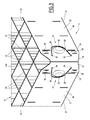
- the nuclear fuel assembly 2 for boiling water reactor illustrated on Figure 1 is elongated along an assembly axis L extending vertically when the fuel assembly is disposed inside a nuclear reactor.
- the fuel assembly 2 comprises a bundle of nuclear fuel rods 4, a tubular water channel 6 arranged within the bundle of fuel rods 4, spacer grids 8 distributed along the bundle of fuel rods 4 and maintaining the fuel rods laterally, and a tubular fuel channel 10 surrounding the bundle of fuel rods 4.
- the fuel rods 4 are elongated and extend parallel to each other along the assembly axis L.
- Each fuel rod 4 comprises a tubular cladding, pellets of nuclear fuel stacked inside the cladding and caps closing the ends of the cladding.
- the fuel rods 4 are arranged in a lattice with a interspacing between the fuel rods 4.
- the water channel 6 extends parallel to the fuel rods 4.
- the water channel 6 is arranged for channeling a coolant/moderator flow separately from interspaces between the fuel rods 4.
- the water channel 6 typically replaces one or several fuel rods 4 in the lattice.
- the spacer grids 8 are distributed in space relationship along the fuel rods 4. Each spacer grid 8 extends transversally to the assembly axis L. Each spacer grid 8 defines a lattice of cells 16 each for generally receiving a fuel rod 4 and an opening 18 for receiving the water channel 6. The fuel rods 4 are maintained laterally by each of the spacer grids 8. The water channel 6 passes through the corresponding opening 18 of the spacer grids 8. Each spacer grid 8 is secured to the water channel 6.
- the fuel channel 10 extends parallel to the fuel rods 4.
- the fuel channel 10 encases the bundle of fuel rods 4 and the water channel 6.
- the fuel channel 10 is arranged for channeling a coolant/moderator flow between and about the fuel rods 4.
- the fuel assembly 2 typically comprises a lower nozzle and an upper nozzle spaced along assembly axis L, the fuel rods 4, the water channel 6 and the fuel channel 10 extending between the lower nozzle and the upper nozzle, with the water channel 6 and the fuel channel 10 connecting the lower nozzle and the upper nozzle.
- the fuel assembly 2 is placed in a nuclear reactor with the assembly axis L being substantially vertical and the lower nozzle partly inserted into a coolant/moderator outlet provided in a bottom plate of the reactor.
- a coolant/moderator flow exiting the outlet flows into the lower nozzle and splits into a first coolant/moderator flow flowing in the water channel 6 separately from the fuel rods 4 and a second coolant/moderator flow flowing in the fuel channel 10 between and around the fuel rods 4.
- the spacer grids 8 may be similar. One spacer grid 8 according to the invention will be further described in reference to Figures 2 - 4 .
- FIG. 2 illustrates the spacer grid 8 received in the fuel channel 10, without the fuel rods and the water channel for the sake of clarity.
- the spacer grid 8 exhibits a square peripheral contour.
- the spacer grid 8 comprises fours sides joined by pairs at four corners.
- the spacer grid 8 may exhibit another shape. It may namely exhibit a polygonal shape, for instance a hexagonal contour with six sides joined by pairs at six corners.
- the spacer grid 8 comprises a peripheral band 11 delimiting the peripheral contour of the spacer grid 8.
- the peripheral band 11 is composed of elongated peripheral strips 12 each defining one respective side of the peripheral band 11.
- the spacer grid 8 comprises interlaced intermediate strips 14 extending between two opposed peripheral strips 12 and defining a lattice of cells 16, 16A each for generally receiving one respective fuel rod 4 and at least one opening 18 for receiving the water channel 6.
- the intermediate strips 14 comprise a first set of parallel strips extending in a first direction and a second set of parallel strips extending in a second direction different from the first direction and intersecting the strips of the first set.
- Peripheral cells 16, 16A are delimited outwardly by the peripheral strips 12.
- the spacer grid 8 comprises corner cells 16A located at the corners of the spacer grid 8 and each delimited by the end portions 24 of two adjacent peripheral strips 12.
- the fuel channel 10 exhibits a transverse section corresponding to peripheral contour of the spacer grid 8.
- the fuel channel 10 comprises inner walls 20.
- the spacer grid 8 is received within the fuel channel 10 with a transverse spacing between each side of the peripheral band 11 and a facing inner wall 20 of the fuel channel 10.
- the spacer grid 8 comprises positioning means for maintaining spacing between the peripheral band 11 and the inner walls 20 of the fuel channel 10.
- the positioning means comprise elastically deformable springs 22 provided on the peripheral band 11 for biasing the peripheral band 11 away from inner walls 20 of the fuel channel 10. Each spring 22 protrudes outwardly from the outer face 40 of the peripheral band 11.
- Each peripheral strip 12 is provided with one spring 22 on each longitudinal end portion 24 of the peripheral strip 12.
- two springs 22 are provided adjacent to a corner of the peripheral contour of the spacer grid 8, one on each of the two adjacent peripheral strips 12 defining the corner.
- each spring 22 is stamped in the corresponding peripheral strip 12. More specifically, each spring 22 comprises an elastically flexible cantilevered tab 26 stamped in the peripheral strip 12. The tab 26 is delimited in the peripheral strip 12 by an elongated curved slot 28. The tab 26 is delimited by the slot 28 and an imaginary line joining the opposed ends 30 of the slot 28.
- the imaginary line extends substantially transversally to the longitudinal edges 32 of the peripheral strip 12 of the peripheral band 11.
- Each spring 22 extends in cantilever fashion away from the adjacent extremity 34 of the corresponding peripheral strip 12 and thus away from the edge of the adjacent corner.
- Each spring 22 is provided in the peripheral band 11, between the longitudinal edges 32 of the peripheral band 11.
- At least one spring 22 or each spring 22 extends in cantilever fashion towards the adjacent extremity 34 of the corresponding peripheral strip 12 and thus towards the edge of the adjacent corner.
- the imaginary line of at least one spring 22 or the imaginary line of each spring 22 extends substantially parallel to the two longitudinal edges 32 of the peripheral strip 12, the at least one spring 22 or each spring 22 extends in cantilever fashion towards one longitudinal edge 32 of the peripheral strip 12.
- the slot 28 is curved such that it exhibits a generally U-shape with two diverging branches (or V-shape with a rounded tip).
- the tab 26 converges from its base towards its free tip.
- the tab 26 protrudes from the outer face 40 of the peripheral strip 12 oriented outwardly with respect to the spacer grid 8.
- the spring 22 comprises a rigid contact projection 36 provided at the free tip of the tab 26.
- the contact projection 36 protrudes outwardly from the tab 26 to contact the facing inner wall 20 of the fuel channel 10.
- the contact projection 36 is provided for instance as a dimple stamped in the tab 26.
- Each peripheral strip 12 comprises at least one rigid stop or motion limiter 38 formed in the peripheral strip 12 for limiting motion of the peripheral strip 12 towards the facing inner wall 20 of the fuel channel 10 and a subsequent overstress of the associated spring 22.
- Each motion limiter 38 is provided for instance as a rigid dimple stamped in the peripheral strip 12 and protruding outwardly on the outer face 40 of the peripheral strip 12.
- two motion limiters 38 are provided on two opposite sides of the spring 22. More specifically, one motion limiter 38 is provided above the spring 22 and the other motion limiter 38 is below the spring 22. Alternatively, the two motion limiters 38 are provided one in front of the spring 22 adjacent the free end of the spring 22 and the other behind the spring 22 adjacent the hinged end of the spring 22. Alternatively, only one motion limiter 38 is provided above the spring 22, below the spring 22, in front of the spring 22 adjacent the free end of the spring 22 or behind the spring 22 adjacent the hinged end of the spring 22. Alternatively more than two motion limiters may be provided.
- Each motion limiter 38 exhibits a protruding height inferior to the protruding height of the associated spring 22 in the free state of the spring 22.
- the peripheral band 11 comprising elastically deformable springs 22 allows elastic positioning of the spacer grid 8 in the fuel channel 10 with an appropriate adjustable force to ensure appropriate spacing and good performances.
- Motion limiters 38 avoid overstress of the springs 22 and provide minimal spacing.
- the peripheral strip 12 comprises two identical springs 22, one at each end portion 24 of the peripheral strip 12.
- one peripheral strip 12 may comprise two different springs 22 exhibiting different shapes, heights and/or spring rates, e.g. for obtaining a specific positioning of the spacer grid 8 relative to the fuel channel 10, namely an off-centered positioning.
- peripheral strips 12 of a spacer grid 8 may comprise identical springs 22 or alternatively different springs 22 exhibiting shapes, heights and/or spring rates, e.g. for obtaining a specific positioning of the spacer grid 8 relative to the fuel channel 10, namely an off-centered positioning.
- the spring 22 integrally formed in one-piece in a peripheral strip 12 results in a simplified design of the spacer grid 8 and a reduced number of fabrication steps and reduced flow resistance, namely as compared to springs assembled to the peripheral band 11.
- springs 22 are provided at the two end portions 24 of each peripheral strip 12 whereby two springs 22 are provided close to each corner of the spacer grid 8 on the two corresponding sides.
- a peripheral strip 12 may be provided with one spring 22 on one end portion 24 of the peripheral strip 12.
- the spacer grid 8 might thus be provided with springs 22 adjacent only to every other corners of the spacer grid 8, e.g. springs 22 adjacent to two diagonally opposed corners.
- At least one of the peripheral strips 12 of a spacer grid 8 may comprise more than two springs 22 for instance spaced along the peripheral band 11 transversally to the assembly axis L.
- the peripheral band 11 is composed of several initially separate peripheral strips 12 assembled in pairs at their longitudinal end, e.g. by welding.
- the peripheral band 11 delimits a continuous closed contour.
- Each pair of adjacent mutually assembled end portions 24 delimits together with two intersecting intermediate strips 14 a corner cell 16A of closed contour adapted for transversely maintaining a fuel rod 4 received in the corner cell 16A.
- Each corner cell 16A is located at a corner of the spacer grid 8.
- peripheral strips 12 are made in one-piece and are portions of a same single piece of metal bent and assembled at its longitudinal ends to define the peripheral band 11.
- the peripheral band 11 is cut at a corner of the spacer grid 8 in such a manner that the two adjacent end portions 24 of adjacent peripheral strips 12 end at a distance from each other and are separated by an aperture 42.
- the cut peripheral band 11 is discontinuous.
- This alternative embodiment may be implemented with the spring 22 as described above.
- each end portion 24 is free and forms a cantilevered positioning spring 22 protruding outwardly relative to the spacer grid 8 for contacting a facing wall adjacent the periphery of the spacer grid 8, namely a facing inner wall 20 of the fuel channel 10.
- the end portions 24 thus delimit together with two intersecting intermediate strips 14 a corner cell 16A laterally opened.
- Each end portion 24 defines an elastically flexible cantilevered tab 26 extending in cantilever from a connection of the peripheral strip 12 with an intermediate strip 14.
- Each end portion 24 is configured to contact the facing inner wall 20 of the fuel channel 10 while being elastically deformable for elastically positioning the spacer grid 8.
- the end portions 24 are independently elastically flexible.
- Separate end portions 24 of the peripheral strip 12 allow elastic positioning of the spacer grid 8 while allowing to obtain the spacer grid 8 with a reduced number of parts and a reduced number of operation, namely without welding of the peripheral strip 12 at the corner of the spacer grid 8.
- each end portion 24 is provided with a rigid contact projection 44 protruding outwardly from the tab 26 to contact the facing inner wall 20.
- the contact projection 44 is provided e.g. as a rigid dimple stamped in the end portion 24.
- each end portion 24 is provided with at least one slot 46 to adjust the spring force of the tab 26.
- each peripheral strip 12 is provided with at least one motion limiter 38 located adjacent to the free end portion 24 for avoiding overstress.
- the motion limiter 38 is preferably formed in a fixed portion of the peripheral strip 12 out of the cantilevered end portion 24. As illustrated on Figure 5 , the motion limiter 38 is formed in a fixed portion of the peripheral strip 12 opposite the end portion 24 relative to a connection with an intermediate strip 14.
- the peripheral band 11 is cut at each corner and each peripheral strip 12 has its two end portions 24 configured as springs 22.
- Springs 22 are provided at each corner of the spacer grid 8.
- peripheral strip end portions 24 configured as springs 22 are provided only at a limited number of the corners of the spacer grid 8 inferior to the total number of corners of the spacer grid 8, e.g. at two diagonally opposed corners of the spacer grid 8.
- one peripheral strip 12 may have one end portion 24 configured as a spring 22 and the other opposite end portion 24 assembled to that of another peripheral strip 12 and optionally provided with spring 22, projection 36 and motion limiter 38 according to the first embodiment of the invention.
- the bundle of fuel rods 4 may comprise full-length fuel rods 4 and part-length fuel rods 4 of shorter length than the full-length fuel rods.
- a spacer grid 8 provided with a peripheral band 11 cut at a corner is especially adapted when the bundle of fuel rods 4 comprises a part-length fuel rod at said corner.
- the spacer grid 8 exhibits a square peripheral contour and defines a 11 x11 square lattice of cells 16 with the opening 18 replacing a 3x3 array of cells 16.
- Other arrangements may be contemplated by varying the number of cells 16 in the lattice (e.g. 9x9, 10x10 ... 12x12), the peripheral contour of the spacer grid 8 and corresponding lattice (for instance square shaped, rectangular shaped or hexagonal shaped).
- the number, shape and size of the water channel 6 may vary.
- the number of openings 18 for receiving water channel(s) or water rods may vary correspondingly.
- the invention applies in particular to fuel assemblies comprising a fuel channel, where it is preferable to maintain an adequate spacing between the bundle of fuel rods and the inner walls of the fuel channel to allow adequate flow of coolant/moderator in the fuel channel between and around the fuel rods, i.e. namely to BWR or VVER fuel assemblies.
Abstract
The nuclear fuel assembly spacer grid (8) defines a lattice of cells (16) for receiving fuel rods (4). The spacer grid (8) comprises a peripheral band (11) composed of at least one peripheral strip (12) delimiting a portion of the peripheral contour of the spacer grid (8), and at least one spacer grid positioning spring (22) elastically deformable and formed in the peripheral band (11).
Description
- The present invention relates to a nuclear fuel assembly spacer grid defining a lattice of cells for receiving fuel rods.
- A boiling water reactor nuclear fuel assembly (or "BWR fuel assembly") generally comprises a bundle of fuel rods maintained laterally by spacer grids distributed along the bundle of fuel rods, at least one tubular water channel provided within the bundle of fuel rods for channeling a flow of coolant/moderator separately from the fuel rods and a tubular fuel channel encasing the bundle of fuel rods for channeling a flow of coolant/moderator between and about the fuel rods. Similarly, a water-water energetic reactor nuclear fuel assembly (or "VVER fuel assembly") generally comprises a bundle of fuel rods maintained laterally by spacer grids distributed along the bundle of fuel rods, at least one water rod provided within the bundle of fuel rods for channeling a flow of coolant/moderator separately from the fuel rods and a tubular fuel channel encasing the bundle of fuel rods for channeling a flow of coolant/moderator between and about the fuel rods.
- A spacer grid generally defines a lattice of cells for receiving fuel rods and comprises a peripheral band composed of peripheral strips and delimiting the peripheral contour of the spacer grid. It preferably comprises positioning means provided on the peripheral band for ensuring an adequate lateral positioning of the spacer grid inside the fuel channel for ensuring an adequate flow of coolant/moderator between and about the fuel rods, namely about the peripheral fuel rods located adjacent to the inner walls of the fuel channel.
-
US 2005/0246961 ,EP 0 709 0857 US 6 156 043 disclose spacer grids comprising a peripheral band provided with rigid tabs, lobs or stops protruding outwardly from the outer periphery of the peripheral band and formed in the peripheral band and/or assembled to the peripheral band. - The invention aims at providing a nuclear fuel assembly spacer grid allowing good lateral positioning of the bundle of fuel rods within the fuel channel, while being obtainable easily and at low cost.
- To this end, the invention proposes a nuclear fuel assembly spacer grid defining a lattice of cells for receiving fuel rods, wherein the spacer grid comprises a peripheral band composed of at least one peripheral strip delimiting a portion of the peripheral contour of the spacer grid, and at least one spacer grid positioning spring elastically deformable and formed in the peripheral band.
- In other embodiments, the spacer grid comprises one or several of the following features, taken in isolation or in any technically feasible combination:
- the at least one spring is cantilevered;
- the at least one spring is stamped in the peripheral band ;
- the at least one spring is delimited in the peripheral band by at least one elongated slot cut in the peripheral band;
- the at least one elongated slot is a curved slot;
- the at least one spring comprises a flexible cantilevered tab and a rigid contact projection protruding outwardly from the tab;
- the at least one spring is adjacent to a longitudinal end of one of the at least one peripheral strip;
- two springs are formed in one of the at least one peripheral strip each adjacent to a respective longitudinal end of the peripheral strip;
- the peripheral band is composed of several peripheral strips each delimiting a side of the peripheral contour of the spacer grid and each comprising two springs each adjacent to a respective longitudinal end of the corresponding peripheral strip;
- one spring is formed by one free cantilevered end portion of the peripheral band;
- one corner cell is delimited by two peripheral strip free end portions of two peripheral strips of the peripheral band delimiting two adjacent sides of the peripheral contour of the spacer grid, said free end portions being separated from each other by an aperture such that the or each cell corner is laterally opened;
- each corner cell is delimited by two free end portions of two adjacent peripheral strips separated by an aperture;
- each free end portion delimiting a laterally opened corner cell forms a spacer grid positioning spring;
- one motion limiter associated to the at least one spring and formed in the peripheral band adjacent to the at least one spring and protruding outwardly;
- an assembly of interlaced strips comprising intersecting sets of peripheral strips and intermediate strips distributed between the peripheral strips.
- The invention further relates to a nuclear fuel assembly comprising a bundle of fuel rods, a fuel channel and at least one spacer grid as defined above for laterally positioning the bundle of fuel rods within the fuel channel.
- The invention and its advantages will be better understood on reading the following description given solely by way of example and with reference to the appended drawings, in which:
-
Figure 1 is a partial sectional side view of a BWR nuclear fuel assembly; -
Figure 2 is a top view of a spacer grid received in a fuel channel of the nuclear fuel assembly ofFigure 1 , according to an embodiment of the invention; -
Figure 3 is a perspective view of a corner of the spacer grid ofFigure 2 ; -
Figure 4 is a side elevation view of a peripheral strip of the spacer grid ofFigures 2 and3 ; -
Figure 5 is a perspective view of a corner of a spacer grid according to another embodiment of the invention. - The
nuclear fuel assembly 2 for boiling water reactor illustrated onFigure 1 is elongated along an assembly axis L extending vertically when the fuel assembly is disposed inside a nuclear reactor. - The
fuel assembly 2 comprises a bundle ofnuclear fuel rods 4, atubular water channel 6 arranged within the bundle offuel rods 4,spacer grids 8 distributed along the bundle offuel rods 4 and maintaining the fuel rods laterally, and atubular fuel channel 10 surrounding the bundle offuel rods 4. - The
fuel rods 4 are elongated and extend parallel to each other along the assembly axis L. Eachfuel rod 4 comprises a tubular cladding, pellets of nuclear fuel stacked inside the cladding and caps closing the ends of the cladding. Thefuel rods 4 are arranged in a lattice with a interspacing between thefuel rods 4. - The
water channel 6 extends parallel to thefuel rods 4. Thewater channel 6 is arranged for channeling a coolant/moderator flow separately from interspaces between thefuel rods 4. Thewater channel 6 typically replaces one orseveral fuel rods 4 in the lattice. - The
spacer grids 8 are distributed in space relationship along thefuel rods 4. Eachspacer grid 8 extends transversally to the assembly axis L. Eachspacer grid 8 defines a lattice ofcells 16 each for generally receiving afuel rod 4 and anopening 18 for receiving thewater channel 6. Thefuel rods 4 are maintained laterally by each of thespacer grids 8. Thewater channel 6 passes through thecorresponding opening 18 of thespacer grids 8. Eachspacer grid 8 is secured to thewater channel 6. - The
fuel channel 10 extends parallel to thefuel rods 4. Thefuel channel 10 encases the bundle offuel rods 4 and thewater channel 6. Thefuel channel 10 is arranged for channeling a coolant/moderator flow between and about thefuel rods 4. - The
fuel assembly 2 typically comprises a lower nozzle and an upper nozzle spaced along assembly axis L, thefuel rods 4, thewater channel 6 and thefuel channel 10 extending between the lower nozzle and the upper nozzle, with thewater channel 6 and thefuel channel 10 connecting the lower nozzle and the upper nozzle. - In operation, the
fuel assembly 2 is placed in a nuclear reactor with the assembly axis L being substantially vertical and the lower nozzle partly inserted into a coolant/moderator outlet provided in a bottom plate of the reactor. A coolant/moderator flow exiting the outlet flows into the lower nozzle and splits into a first coolant/moderator flow flowing in thewater channel 6 separately from thefuel rods 4 and a second coolant/moderator flow flowing in thefuel channel 10 between and around thefuel rods 4. - The
spacer grids 8 may be similar. Onespacer grid 8 according to the invention will be further described in reference toFigures 2 - 4 . -
Figure 2 illustrates thespacer grid 8 received in thefuel channel 10, without the fuel rods and the water channel for the sake of clarity. - As illustrated on
Figure 2 , thespacer grid 8 exhibits a square peripheral contour. Thespacer grid 8 comprises fours sides joined by pairs at four corners. Alternatively, thespacer grid 8 may exhibit another shape. It may namely exhibit a polygonal shape, for instance a hexagonal contour with six sides joined by pairs at six corners. - The
spacer grid 8 comprises aperipheral band 11 delimiting the peripheral contour of thespacer grid 8. Theperipheral band 11 is composed of elongatedperipheral strips 12 each defining one respective side of theperipheral band 11. - The
spacer grid 8 comprises interlacedintermediate strips 14 extending between two opposedperipheral strips 12 and defining a lattice ofcells respective fuel rod 4 and at least one opening 18 for receiving thewater channel 6. Theintermediate strips 14 comprise a first set of parallel strips extending in a first direction and a second set of parallel strips extending in a second direction different from the first direction and intersecting the strips of the first set.Peripheral cells peripheral strips 12. Thespacer grid 8 comprisescorner cells 16A located at the corners of thespacer grid 8 and each delimited by theend portions 24 of two adjacentperipheral strips 12. - The
fuel channel 10 exhibits a transverse section corresponding to peripheral contour of thespacer grid 8. Thefuel channel 10 comprisesinner walls 20. - The
spacer grid 8 is received within thefuel channel 10 with a transverse spacing between each side of theperipheral band 11 and a facinginner wall 20 of thefuel channel 10. - The
spacer grid 8 comprises positioning means for maintaining spacing between theperipheral band 11 and theinner walls 20 of thefuel channel 10. - The positioning means comprise elastically
deformable springs 22 provided on theperipheral band 11 for biasing theperipheral band 11 away frominner walls 20 of thefuel channel 10. Eachspring 22 protrudes outwardly from theouter face 40 of theperipheral band 11. - Each
peripheral strip 12 is provided with onespring 22 on eachlongitudinal end portion 24 of theperipheral strip 12. - As illustrated on
Figure 3 , twosprings 22 are provided adjacent to a corner of the peripheral contour of thespacer grid 8, one on each of the two adjacentperipheral strips 12 defining the corner. - As illustrated on
Figures 3 and4 , eachspring 22 is stamped in the correspondingperipheral strip 12. More specifically, eachspring 22 comprises an elastically flexible cantileveredtab 26 stamped in theperipheral strip 12. Thetab 26 is delimited in theperipheral strip 12 by an elongatedcurved slot 28. Thetab 26 is delimited by theslot 28 and an imaginary line joining the opposed ends 30 of theslot 28. - As illustrated on
Figures 3 and4 , the imaginary line extends substantially transversally to thelongitudinal edges 32 of theperipheral strip 12 of theperipheral band 11. Eachspring 22 extends in cantilever fashion away from theadjacent extremity 34 of the correspondingperipheral strip 12 and thus away from the edge of the adjacent corner. Eachspring 22 is provided in theperipheral band 11, between thelongitudinal edges 32 of theperipheral band 11. - Optionally or alternatively, at least one
spring 22 or eachspring 22 extends in cantilever fashion towards theadjacent extremity 34 of the correspondingperipheral strip 12 and thus towards the edge of the adjacent corner. - Optionally or alternatively, the imaginary line of at least one
spring 22 or the imaginary line of eachspring 22 extends substantially parallel to the twolongitudinal edges 32 of theperipheral strip 12, the at least onespring 22 or eachspring 22 extends in cantilever fashion towards onelongitudinal edge 32 of theperipheral strip 12. - The
slot 28 is curved such that it exhibits a generally U-shape with two diverging branches (or V-shape with a rounded tip). Thetab 26 converges from its base towards its free tip. - In a free state of the
spring 22, thetab 26 protrudes from theouter face 40 of theperipheral strip 12 oriented outwardly with respect to thespacer grid 8. - The
spring 22 comprises arigid contact projection 36 provided at the free tip of thetab 26. Thecontact projection 36 protrudes outwardly from thetab 26 to contact the facinginner wall 20 of thefuel channel 10. Thecontact projection 36 is provided for instance as a dimple stamped in thetab 26. - Each
peripheral strip 12 comprises at least one rigid stop ormotion limiter 38 formed in theperipheral strip 12 for limiting motion of theperipheral strip 12 towards the facinginner wall 20 of thefuel channel 10 and a subsequent overstress of the associatedspring 22. - Each
motion limiter 38 is provided for instance as a rigid dimple stamped in theperipheral strip 12 and protruding outwardly on theouter face 40 of theperipheral strip 12. - As illustrated on
Figures 3 and4 , twomotion limiters 38 are provided on two opposite sides of thespring 22. More specifically, onemotion limiter 38 is provided above thespring 22 and theother motion limiter 38 is below thespring 22. Alternatively, the twomotion limiters 38 are provided one in front of thespring 22 adjacent the free end of thespring 22 and the other behind thespring 22 adjacent the hinged end of thespring 22. Alternatively, only onemotion limiter 38 is provided above thespring 22, below thespring 22, in front of thespring 22 adjacent the free end of thespring 22 or behind thespring 22 adjacent the hinged end of thespring 22. Alternatively more than two motion limiters may be provided. - Each
motion limiter 38 exhibits a protruding height inferior to the protruding height of the associatedspring 22 in the free state of thespring 22. - The
peripheral band 11 comprising elasticallydeformable springs 22 allows elastic positioning of thespacer grid 8 in thefuel channel 10 with an appropriate adjustable force to ensure appropriate spacing and good performances.Motion limiters 38 avoid overstress of thesprings 22 and provide minimal spacing. - As illustrated on
Figures 3 and4 , theperipheral strip 12 comprises twoidentical springs 22, one at eachend portion 24 of theperipheral strip 12. Alternatively, oneperipheral strip 12 may comprise twodifferent springs 22 exhibiting different shapes, heights and/or spring rates, e.g. for obtaining a specific positioning of thespacer grid 8 relative to thefuel channel 10, namely an off-centered positioning. - Similarly, the
peripheral strips 12 of aspacer grid 8 may compriseidentical springs 22 or alternativelydifferent springs 22 exhibiting shapes, heights and/or spring rates, e.g. for obtaining a specific positioning of thespacer grid 8 relative to thefuel channel 10, namely an off-centered positioning. - The
spring 22 integrally formed in one-piece in aperipheral strip 12 results in a simplified design of thespacer grid 8 and a reduced number of fabrication steps and reduced flow resistance, namely as compared to springs assembled to theperipheral band 11. - ln the embodiments of
Figures 2 - 4 , springs 22 are provided at the twoend portions 24 of eachperipheral strip 12 whereby twosprings 22 are provided close to each corner of thespacer grid 8 on the two corresponding sides. - Alternatively, a
peripheral strip 12 may be provided with onespring 22 on oneend portion 24 of theperipheral strip 12. Thespacer grid 8 might thus be provided withsprings 22 adjacent only to every other corners of thespacer grid 8, e.g. springs 22 adjacent to two diagonally opposed corners. - Alternatively, at least one of the
peripheral strips 12 of aspacer grid 8 may comprise more than twosprings 22 for instance spaced along theperipheral band 11 transversally to the assembly axis L. - In the embodiment of
Figures 2 - 4 , theperipheral band 11 is composed of several initially separateperipheral strips 12 assembled in pairs at their longitudinal end, e.g. by welding. Theperipheral band 11 delimits a continuous closed contour. - Each pair of adjacent mutually assembled
end portions 24 delimits together with two intersecting intermediate strips 14 acorner cell 16A of closed contour adapted for transversely maintaining afuel rod 4 received in thecorner cell 16A. Eachcorner cell 16A is located at a corner of thespacer grid 8. - ln an alternative embodiment, the
peripheral strips 12 are made in one-piece and are portions of a same single piece of metal bent and assembled at its longitudinal ends to define theperipheral band 11. - In the alternative embodiment of
Figure 5 illustrating a corner of aspacer grid 8 in perspective view, theperipheral band 11 is cut at a corner of thespacer grid 8 in such a manner that the twoadjacent end portions 24 of adjacentperipheral strips 12 end at a distance from each other and are separated by anaperture 42. The cutperipheral band 11 is discontinuous. This alternative embodiment may be implemented with thespring 22 as described above. - Alternatively, as illustrated on
Figure 5 , eachend portion 24 is free and forms a cantileveredpositioning spring 22 protruding outwardly relative to thespacer grid 8 for contacting a facing wall adjacent the periphery of thespacer grid 8, namely a facinginner wall 20 of thefuel channel 10. - The
end portions 24 thus delimit together with two intersecting intermediate strips 14 acorner cell 16A laterally opened. - Each
end portion 24 defines an elastically flexible cantileveredtab 26 extending in cantilever from a connection of theperipheral strip 12 with anintermediate strip 14. - Each
end portion 24 is configured to contact the facinginner wall 20 of thefuel channel 10 while being elastically deformable for elastically positioning thespacer grid 8. Theend portions 24 are independently elastically flexible. -
Separate end portions 24 of theperipheral strip 12 allow elastic positioning of thespacer grid 8 while allowing to obtain thespacer grid 8 with a reduced number of parts and a reduced number of operation, namely without welding of theperipheral strip 12 at the corner of thespacer grid 8. - Optionally, each
end portion 24 is provided with arigid contact projection 44 protruding outwardly from thetab 26 to contact the facinginner wall 20. Thecontact projection 44 is provided e.g. as a rigid dimple stamped in theend portion 24. By varying the height and length of the dimple, the positioning performances of thespacer grid 8 may be optimized. - Optionally, each
end portion 24 is provided with at least oneslot 46 to adjust the spring force of thetab 26. - Optionally, each
peripheral strip 12 is provided with at least onemotion limiter 38 located adjacent to thefree end portion 24 for avoiding overstress. Themotion limiter 38 is preferably formed in a fixed portion of theperipheral strip 12 out of thecantilevered end portion 24. As illustrated onFigure 5 , themotion limiter 38 is formed in a fixed portion of theperipheral strip 12 opposite theend portion 24 relative to a connection with anintermediate strip 14. - In one embodiment, the
peripheral band 11 is cut at each corner and eachperipheral strip 12 has its twoend portions 24 configured as springs 22.Springs 22 are provided at each corner of thespacer grid 8. - ln an alternative embodiment, peripheral
strip end portions 24 configured assprings 22 are provided only at a limited number of the corners of thespacer grid 8 inferior to the total number of corners of thespacer grid 8, e.g. at two diagonally opposed corners of thespacer grid 8. ln such an embodiment, oneperipheral strip 12 may have oneend portion 24 configured as aspring 22 and the otheropposite end portion 24 assembled to that of anotherperipheral strip 12 and optionally provided withspring 22,projection 36 andmotion limiter 38 according to the first embodiment of the invention. - The bundle of
fuel rods 4 may comprise full-length fuel rods 4 and part-length fuel rods 4 of shorter length than the full-length fuel rods. Aspacer grid 8 provided with aperipheral band 11 cut at a corner is especially adapted when the bundle offuel rods 4 comprises a part-length fuel rod at said corner. - As illustrated on
Figure 2 , thespacer grid 8 exhibits a square peripheral contour and defines a 11 x11 square lattice ofcells 16 with theopening 18 replacing a 3x3 array ofcells 16. Other arrangements may be contemplated by varying the number ofcells 16 in the lattice (e.g. 9x9, 10x10 ... 12x12), the peripheral contour of thespacer grid 8 and corresponding lattice (for instance square shaped, rectangular shaped or hexagonal shaped). Similarly, the number, shape and size of thewater channel 6 may vary. Hence, the number ofopenings 18 for receiving water channel(s) or water rods (oneopening 18, twoopenings 18 or more) and the size and shape of theopenings 18 for receiving water channels or water rods (1x1, 1 x2, 2x1, 2x2, 2x3, 3x3...) may vary correspondingly. - The invention applies in particular to fuel assemblies comprising a fuel channel, where it is preferable to maintain an adequate spacing between the bundle of fuel rods and the inner walls of the fuel channel to allow adequate flow of coolant/moderator in the fuel channel between and around the fuel rods, i.e. namely to BWR or VVER fuel assemblies.
Claims (16)
- A nuclear fuel assembly spacer grid (8) defining a lattice of cells (16) for receiving fuel rods (4) wherein the spacer grid (8) comprises a peripheral band (11) composed of at least one peripheral strip (12) delimiting a portion of the peripheral contour of the spacer grid (8), and at least one spacer grid positioning spring (22) elastically deformable and formed in the peripheral band (11).
- Spacer grid according to claim 1, wherein the at least one spring (22) is cantilevered.
- Spacer grid according to claim 1 or 2, wherein the at least one spring (22) is stamped in the peripheral band (11).
- Spacer grid according to any preceding claim, wherein the at least one spring (22) is delimited in the peripheral band (11) by at least one elongated slot (28, 46) cut in the peripheral band (11).
- Spacer grid according to claim 4, wherein the at least one elongated slot (28, 46) is a curved slot (28).
- Spacer grid according to any preceding claim, wherein the at least one spring (22) comprises a flexible cantilevered tab (26) and a rigid contact projection (36, 44) protruding outwardly from the tab (26).
- Spacer grid according to any preceding claim, wherein the at least one spring (22) is adjacent to a longitudinal end of one of the at least one peripheral strip (12).
- Spacer grid according to claim 7, comprising two springs (22) formed in one of the at least one peripheral strip (12) each adjacent to a respective longitudinal end of the peripheral strip (12).
- Spacer grid according to claim 8, wherein the peripheral band (11) is composed of several peripheral strips (12) each delimiting a side of the peripheral contour of the spacer grid (8) and each comprising two springs (22) each adjacent to a respective longitudinal end of the corresponding peripheral strip (12).
- Spacer grid according to any preceding claim, comprising at least one spring (22) formed by one free cantilevered end portion (24) of the peripheral band (11).
- Spacer grid according to claim 10, comprising at least one corner cell (16A) delimited by two peripheral strip free end portions (24) of two peripheral strips (12) of the peripheral band (11) delimiting two adjacent sides of the peripheral contour of the spacer grid (8), said free end portions (24) being separated from each other by an aperture (42) such that the or each cell corner (16A) is laterally opened.
- Spacer grid according to claim 11, wherein each corner cell (16A) is delimited by two free end portions (24) of two adjacent peripheral strips (12) separated by an aperture (42).
- Spacer grid according to claim 11 or 12, wherein each free end portion (24) delimiting a laterally opened corner cell (16A) forms a spacer grid positioning spring (22).
- Spacer grid according to any preceding claim, comprising at least one motion limiter (38) associated to the at least one spring (22) and formed in the peripheral band (11) adjacent to the at least one spring (22) and protruding outwardly.
- Spacer grid according to any preceding claim, composed of an assembly of interlaced strips comprising intersecting sets of peripheral strips (12) and intermediate strips (14) distributed between the peripheral strips (12).
- A nuclear fuel assembly (2) comprising a bundle of fuel rods (4), a fuel channel (10) and at least one spacer grid (8) according to any preceding claim for laterally positioning the bundle of fuel rods (4) within the fuel channel (10).
Priority Applications (8)
| Application Number | Priority Date | Filing Date | Title |
|---|---|---|---|
| EP11305626A EP2525367A1 (en) | 2011-05-20 | 2011-05-20 | Nuclear fuel assembly spacer grid and corresponding nuclear fuel assembly |
| ES12720878.3T ES2583087T3 (en) | 2011-05-20 | 2012-05-14 | Separating grid for nuclear fuel element and corresponding nuclear fuel element |
| KR1020137032630A KR20140033103A (en) | 2011-05-20 | 2012-05-14 | Nuclear fuel assembly spacer grid and corresponding nuclear fuel assembly |
| CN201280024521.XA CN103548092B (en) | 2011-05-20 | 2012-05-14 | Nuclear fuel assembly spacer grid and corresponding nuclear fuel assembly |
| US13/822,565 US9793012B2 (en) | 2011-05-20 | 2012-05-14 | Nuclear fuel assembly spacer grid and corresponding nuclear fuel assembly |
| EP12720878.3A EP2710605B1 (en) | 2011-05-20 | 2012-05-14 | Nuclear fuel assembly spacer grid and corresponding nuclear fuel assembly |
| JP2014510765A JP6067684B2 (en) | 2011-05-20 | 2012-05-14 | Nuclear fuel assembly spacer grid and corresponding nuclear fuel assembly |
| PCT/EP2012/058911 WO2012159916A1 (en) | 2011-05-20 | 2012-05-14 | Nuclear fuel assembly spacer grid and corresponding nuclear fuel assembly |
Applications Claiming Priority (1)
| Application Number | Priority Date | Filing Date | Title |
|---|---|---|---|
| EP11305626A EP2525367A1 (en) | 2011-05-20 | 2011-05-20 | Nuclear fuel assembly spacer grid and corresponding nuclear fuel assembly |
Publications (1)
| Publication Number | Publication Date |
|---|---|
| EP2525367A1 true EP2525367A1 (en) | 2012-11-21 |
Family
ID=44561229
Family Applications (2)
| Application Number | Title | Priority Date | Filing Date |
|---|---|---|---|
| EP11305626A Withdrawn EP2525367A1 (en) | 2011-05-20 | 2011-05-20 | Nuclear fuel assembly spacer grid and corresponding nuclear fuel assembly |
| EP12720878.3A Active EP2710605B1 (en) | 2011-05-20 | 2012-05-14 | Nuclear fuel assembly spacer grid and corresponding nuclear fuel assembly |
Family Applications After (1)
| Application Number | Title | Priority Date | Filing Date |
|---|---|---|---|
| EP12720878.3A Active EP2710605B1 (en) | 2011-05-20 | 2012-05-14 | Nuclear fuel assembly spacer grid and corresponding nuclear fuel assembly |
Country Status (7)
| Country | Link |
|---|---|
| US (1) | US9793012B2 (en) |
| EP (2) | EP2525367A1 (en) |
| JP (1) | JP6067684B2 (en) |
| KR (1) | KR20140033103A (en) |
| CN (1) | CN103548092B (en) |
| ES (1) | ES2583087T3 (en) |
| WO (1) | WO2012159916A1 (en) |
Families Citing this family (5)
| Publication number | Priority date | Publication date | Assignee | Title |
|---|---|---|---|---|
| US10672521B2 (en) * | 2012-03-23 | 2020-06-02 | Global Nuclear Fuel—Americas, LLC | Spacers with deflection-limited peripheral springs for nuclear fuel assemblies and methods of making the same |
| US10438704B2 (en) * | 2014-12-23 | 2019-10-08 | Westinghouse Electric Company Llc | Nuclear fuel assembly support feature |
| ES2664401T3 (en) * | 2015-02-20 | 2018-04-19 | Westinghouse Electric Sweden Ab | Boiling fuel reactor for a nuclear reactor |
| CN105869681B (en) * | 2016-05-26 | 2018-03-20 | 中广核研究院有限公司 | Fuel assembly and its without outer band grid spacer and band |
| KR102290169B1 (en) * | 2019-12-26 | 2021-08-17 | 한국원자력연구원 | Storage rack for spent fuel assembly in a spent fuel pool |
Citations (9)
| Publication number | Priority date | Publication date | Assignee | Title |
|---|---|---|---|---|
| US5253278A (en) * | 1990-05-25 | 1993-10-12 | Hitachi, Ltd. | Fuel assembly, channel box, production method of channel box, and core of nuclear reactor |
| US5267291A (en) * | 1992-02-21 | 1993-11-30 | General Electric Company | Spacer band with optimized fuel bundle to channel clearance in a boiling water reactor |
| JPH05323073A (en) * | 1992-05-18 | 1993-12-07 | Nuclear Fuel Ind Ltd | Fuel assembly and spacer for fuel assembly |
| EP0709857A1 (en) | 1994-10-25 | 1996-05-01 | General Electric Company | Nuclea fuel assembly channel comprising spacer centering mass |
| US5530729A (en) * | 1993-09-17 | 1996-06-25 | Abb Atom Ab | Fuel assembly and spacer for a boiling reactor |
| US6156043A (en) | 1998-05-26 | 2000-12-05 | Krahn; Henry P. | Soft tissue morsellator |
| WO2003077261A2 (en) * | 2002-03-14 | 2003-09-18 | Framatome Anp Gmbh | Spacer for the fuel element of a boiling water reactor |
| US20050243961A1 (en) * | 2002-10-01 | 2005-11-03 | Framatome Anp Gmbh | Fuel assembly for a boiling water reactor |
| US20050246961A1 (en) | 2004-05-07 | 2005-11-10 | Fabien Dufour | Cable tensioner |
Family Cites Families (16)
| Publication number | Priority date | Publication date | Assignee | Title |
|---|---|---|---|---|
| US4058436A (en) * | 1975-12-05 | 1977-11-15 | Combustion Engineering Inc. | Nuclear reactor seismic fuel assembly grid |
| JPS5510541A (en) | 1978-07-11 | 1980-01-25 | Tokyo Shibaura Electric Co | Method of arranging natural frequency of fuel assembly * and spacer |
| JPS5527940A (en) | 1978-08-21 | 1980-02-28 | Tokyo Shibaura Electric Co | Grid spacer |
| JPS56133680A (en) | 1980-03-25 | 1981-10-19 | Genshi Nenryo Kogyo | Supporting lattice for nuclear fuel assembly |
| JPH01173898A (en) | 1987-09-10 | 1989-07-10 | Mitsubishi Nuclear Fuel Co Ltd | Supporting grid of nuclear reactor fuel assembly |
| JPH0216098U (en) * | 1988-07-18 | 1990-02-01 | ||
| SE464995B (en) * | 1989-11-14 | 1991-07-08 | Asea Atom Ab | BRAINSLEPATRON FOR A COOKAR REACTOR |
| JPH02257092A (en) | 1989-03-30 | 1990-10-17 | Nuclear Fuel Ind Ltd | Ring element type fuel spacer |
| US5139736A (en) * | 1991-04-03 | 1992-08-18 | Combustion Engineering, Inc. | Fuel assembly support grid |
| US5307392A (en) * | 1992-06-29 | 1994-04-26 | Combustion Engineering, Inc. | Energy dissipating outer strip for grid |
| US6117455A (en) | 1994-09-30 | 2000-09-12 | Takeda Chemical Industries, Ltd. | Sustained-release microcapsule of amorphous water-soluble pharmaceutical active agent |
| DE10208502C1 (en) * | 2002-02-27 | 2003-09-25 | Framatome Anp Gmbh | Spacer for a fuel element of a boiling water reactor |
| US7421056B2 (en) * | 2002-03-14 | 2008-09-02 | Areva Np Gmbh | Fuel assembly for a boiling water reactor |
| FR2860334B1 (en) | 2003-09-30 | 2007-12-07 | Framatome Anp | NUCLEAR FUEL ASSEMBLY COMPRISING A REINFORCING MESH DEVICE AND USE OF SUCH A DEVICE IN A NUCLEAR FUEL ASSEMBLY |
| US8599994B2 (en) * | 2007-04-27 | 2013-12-03 | General Electric Company | Fuel bundle and spacer band |
| FR2923321B1 (en) | 2007-11-05 | 2009-12-18 | Areva Np | NUCLEAR FUEL PEN HOLDING GRID, AND FRAME AND ASSEMBLY COMPRISING SUCH A GRID. |
-
2011
- 2011-05-20 EP EP11305626A patent/EP2525367A1/en not_active Withdrawn
-
2012
- 2012-05-14 US US13/822,565 patent/US9793012B2/en active Active
- 2012-05-14 KR KR1020137032630A patent/KR20140033103A/en not_active Application Discontinuation
- 2012-05-14 JP JP2014510765A patent/JP6067684B2/en active Active
- 2012-05-14 EP EP12720878.3A patent/EP2710605B1/en active Active
- 2012-05-14 ES ES12720878.3T patent/ES2583087T3/en active Active
- 2012-05-14 CN CN201280024521.XA patent/CN103548092B/en active Active
- 2012-05-14 WO PCT/EP2012/058911 patent/WO2012159916A1/en active Application Filing
Patent Citations (9)
| Publication number | Priority date | Publication date | Assignee | Title |
|---|---|---|---|---|
| US5253278A (en) * | 1990-05-25 | 1993-10-12 | Hitachi, Ltd. | Fuel assembly, channel box, production method of channel box, and core of nuclear reactor |
| US5267291A (en) * | 1992-02-21 | 1993-11-30 | General Electric Company | Spacer band with optimized fuel bundle to channel clearance in a boiling water reactor |
| JPH05323073A (en) * | 1992-05-18 | 1993-12-07 | Nuclear Fuel Ind Ltd | Fuel assembly and spacer for fuel assembly |
| US5530729A (en) * | 1993-09-17 | 1996-06-25 | Abb Atom Ab | Fuel assembly and spacer for a boiling reactor |
| EP0709857A1 (en) | 1994-10-25 | 1996-05-01 | General Electric Company | Nuclea fuel assembly channel comprising spacer centering mass |
| US6156043A (en) | 1998-05-26 | 2000-12-05 | Krahn; Henry P. | Soft tissue morsellator |
| WO2003077261A2 (en) * | 2002-03-14 | 2003-09-18 | Framatome Anp Gmbh | Spacer for the fuel element of a boiling water reactor |
| US20050243961A1 (en) * | 2002-10-01 | 2005-11-03 | Framatome Anp Gmbh | Fuel assembly for a boiling water reactor |
| US20050246961A1 (en) | 2004-05-07 | 2005-11-10 | Fabien Dufour | Cable tensioner |
Also Published As
| Publication number | Publication date |
|---|---|
| ES2583087T3 (en) | 2016-09-19 |
| CN103548092A (en) | 2014-01-29 |
| US20130251089A1 (en) | 2013-09-26 |
| KR20140033103A (en) | 2014-03-17 |
| US9793012B2 (en) | 2017-10-17 |
| CN103548092B (en) | 2017-02-15 |
| JP6067684B2 (en) | 2017-01-25 |
| JP2014515474A (en) | 2014-06-30 |
| WO2012159916A1 (en) | 2012-11-29 |
| EP2710605A1 (en) | 2014-03-26 |
| EP2710605B1 (en) | 2016-05-04 |
Similar Documents
| Publication | Publication Date | Title |
|---|---|---|
| EP2710605B1 (en) | Nuclear fuel assembly spacer grid and corresponding nuclear fuel assembly | |
| US9443619B2 (en) | Strip for a nuclear fuel assembly spacer grid | |
| KR20150093682A (en) | Fuel rod support insert for a nuclear fuel assembly spacer grid, spacer grid and nuclear fuel assembly | |
| JP6448750B2 (en) | Strips for spacer grids of nuclear fuel assemblies | |
| EP2710602B1 (en) | Nuclear fuel assembly tie plate, upper nozzle and nuclear fuel assembly comprising such a tie plate | |
| TW201312588A (en) | Strip for a nuclear fuel assembly spacer grid | |
| US9196386B2 (en) | Spacer grid for nuclear fuel assembly for reducing high frequency vibration | |
| US8774343B2 (en) | Flow tripping device |
Legal Events
| Date | Code | Title | Description |
|---|---|---|---|
| PUAI | Public reference made under article 153(3) epc to a published international application that has entered the european phase |
Free format text: ORIGINAL CODE: 0009012 |
|
| AK | Designated contracting states |
Kind code of ref document: A1 Designated state(s): AL AT BE BG CH CY CZ DE DK EE ES FI FR GB GR HR HU IE IS IT LI LT LU LV MC MK MT NL NO PL PT RO RS SE SI SK SM TR |
|
| AX | Request for extension of the european patent |
Extension state: BA ME |
|
| STAA | Information on the status of an ep patent application or granted ep patent |
Free format text: STATUS: THE APPLICATION IS DEEMED TO BE WITHDRAWN |
|
| 18D | Application deemed to be withdrawn |
Effective date: 20130522 |