EP2525366A1 - Streifen für ein Abstandsgitter eines Kernbrennstoffbündels - Google Patents
Streifen für ein Abstandsgitter eines Kernbrennstoffbündels Download PDFInfo
- Publication number
- EP2525366A1 EP2525366A1 EP11305628A EP11305628A EP2525366A1 EP 2525366 A1 EP2525366 A1 EP 2525366A1 EP 11305628 A EP11305628 A EP 11305628A EP 11305628 A EP11305628 A EP 11305628A EP 2525366 A1 EP2525366 A1 EP 2525366A1
- Authority
- EP
- European Patent Office
- Prior art keywords
- strip
- tab
- wall portion
- contact portion
- strip according
- Prior art date
- Legal status (The legal status is an assumption and is not a legal conclusion. Google has not performed a legal analysis and makes no representation as to the accuracy of the status listed.)
- Withdrawn
Links
Images


Classifications
-
- G—PHYSICS
- G21—NUCLEAR PHYSICS; NUCLEAR ENGINEERING
- G21C—NUCLEAR REACTORS
- G21C3/00—Reactor fuel elements and their assemblies; Selection of substances for use as reactor fuel elements
- G21C3/30—Assemblies of a number of fuel elements in the form of a rigid unit
- G21C3/32—Bundles of parallel pin-, rod-, or tube-shaped fuel elements
- G21C3/34—Spacer grids
- G21C3/356—Spacer grids being provided with fuel element supporting members
- G21C3/3563—Supporting members formed only by deformations in the strips
-
- G—PHYSICS
- G21—NUCLEAR PHYSICS; NUCLEAR ENGINEERING
- G21C—NUCLEAR REACTORS
- G21C3/00—Reactor fuel elements and their assemblies; Selection of substances for use as reactor fuel elements
- G21C3/30—Assemblies of a number of fuel elements in the form of a rigid unit
- G21C3/32—Bundles of parallel pin-, rod-, or tube-shaped fuel elements
- G21C3/34—Spacer grids
- G21C3/356—Spacer grids being provided with fuel element supporting members
-
- G—PHYSICS
- G21—NUCLEAR PHYSICS; NUCLEAR ENGINEERING
- G21C—NUCLEAR REACTORS
- G21C3/00—Reactor fuel elements and their assemblies; Selection of substances for use as reactor fuel elements
- G21C3/30—Assemblies of a number of fuel elements in the form of a rigid unit
- G21C3/32—Bundles of parallel pin-, rod-, or tube-shaped fuel elements
- G21C3/34—Spacer grids
- G21C3/352—Spacer grids formed of assembled intersecting strips
-
- G—PHYSICS
- G21—NUCLEAR PHYSICS; NUCLEAR ENGINEERING
- G21C—NUCLEAR REACTORS
- G21C3/00—Reactor fuel elements and their assemblies; Selection of substances for use as reactor fuel elements
- G21C3/30—Assemblies of a number of fuel elements in the form of a rigid unit
- G21C3/32—Bundles of parallel pin-, rod-, or tube-shaped fuel elements
- G21C3/322—Means to influence the coolant flow through or around the bundles
-
- Y—GENERAL TAGGING OF NEW TECHNOLOGICAL DEVELOPMENTS; GENERAL TAGGING OF CROSS-SECTIONAL TECHNOLOGIES SPANNING OVER SEVERAL SECTIONS OF THE IPC; TECHNICAL SUBJECTS COVERED BY FORMER USPC CROSS-REFERENCE ART COLLECTIONS [XRACs] AND DIGESTS
- Y02—TECHNOLOGIES OR APPLICATIONS FOR MITIGATION OR ADAPTATION AGAINST CLIMATE CHANGE
- Y02E—REDUCTION OF GREENHOUSE GAS [GHG] EMISSIONS, RELATED TO ENERGY GENERATION, TRANSMISSION OR DISTRIBUTION
- Y02E30/00—Energy generation of nuclear origin
- Y02E30/30—Nuclear fission reactors
Definitions
- the present invention relates to a strip for a nuclear fuel assembly spacer grid comprising interlaced strips defining a lattice of cells for receiving fuel rods and allowing flow of a coolant in a flow direction.
- US 4 879 090 illustrates on Figure 5 thereof a peripheral strip for a nuclear fuel assembly spacer grid, the peripheral strip comprising wall portions to delimit cells and on each wall portion a spring formed by a tab cut out in the strip and motion limiters formed as a pair of bosses embossed in the strip at a distance from the tab.
- a coolant fluid e.g. water
- the spring and the motion limiters provided on each wall portion protrude from the plane of the wall portion towards the center of the same cell delimited by the wall portion and partially obstruct the coolant fluid flow channel.
- An object of the invention is to provide a strip for a nuclear fuel assembly spacer grid limiting the flow resistance of the spacer grid whilst allowing suitable support for the nuclear fuel rods during the whole fuel assembly lifetime and good manufacturability.
- the invention proposes a strip for a nuclear fuel assembly spacer grid for a nuclear fuel assembly spacer grid comprising interlaced strips defining a lattice of cells for receiving fuel rods and allowing flow of a coolant in a flow direction, the strip being of the type comprising a wall portion for delimiting a cell, a spring formed in the strip and provided on the wall portion for biasing the fuel rod extending through the cell away from the wall portion, the spring comprising a cantilevered tab formed in the strip and a contact portion formed at least partially in the tab and protruding from the tab for contacting the fuel rod received in the cell.
- the strip comprises one or several of the following features, taken in isolation or in any technically feasible combination:
- the invention also relates to a spacer grid comprising interlaced strips defining a lattice of cells for receiving fuel rods and allowing flow of a coolant axially upwardly through the spacer grid, at least one of the interlaced strips being a strip as defined above.
- the invention further relates to a nuclear fuel assembly comprising a bundle of fuel rods and an armature for supporting the fuel rods, the armature comprising at least one spacer grid as defined above.
- the nuclear fuel assembly 2 for a pressurized water reactor (PWR) illustrated on Figure 1 comprises a bundle of nuclear fuel rods 4 and an armature 6 for supporting the fuel rods 4.
- the PWR fuel assembly 2 is elongated along an assembly axis L extending vertically when the fuel assembly 2 is disposed inside a nuclear reactor.
- the armature 6 comprises a lower nozzle 8, an upper nozzle 10, a plurality of guide-tubes 12 and a plurality of spacer grids 14.
- the guide-tubes 12 extend parallel to assembly axis L and connect the lower nozzle 8 to the upper nozzle 10 and maintain a predetermined spacing along assembly axis L between the nozzles 8, 10. Each guide-tube 12 opens upwards through the upper nozzle 10 for allowing insertion of a control rod into the guide-tube 12.
- the nuclear fuel assembly 2 for a boiling water reactor (BWR) illustrated on Figure 2 is also elongated along an assembly axis L extending vertically when the fuel assembly 2 is disposed inside a nuclear reactor.
- the BWR fuel assembly 2 comprises a bundle of nuclear fuel rods 4, an armature for maintaining the fuel rods 4 and a tubular fuel channel 15 surrounding the bundle of fuel rods 4.
- the armature typically comprises a lower nozzle and an upper nozzle spaced along assembly axis L, at least one water channel 13 arranged within the bundle of fuel rods 4 and a plurality of spacer grids 14 distributed along the bundle of fuel rods 4.
- the fuel rods 4, the water channel 13 and the fuel channel 15 extend between the lower nozzle and the upper nozzle, with the water channel 13 and the fuel channel 15 connecting the lower nozzle and the upper nozzle.
- the water channel 13 extends parallel to the fuel rods 4.
- the water channel 13 is arranged for channeling a coolant/moderator flow separately from the bundle of fuel rods 4.
- the fuel channel 15 extends parallel to the fuel rods 4.
- the fuel channel 15 encases the bundle of fuel rods 4 and the water channel 13.
- the fuel channel 15 is arranged for channeling a coolant/moderator flow between and about the fuel rods 4.
- the PWR and BWR spacer grids 14 are distributed in spaced relationship along the fuel rods 4.
- Each spacer grid 14 extends transversely to the assembly axis L.
- Each fuel rod 4 comprises a tubular cladding, pellets of nuclear fuel stacked inside the cladding and caps closing the ends of the cladding.
- Each fuel rod 4 extends parallel to assembly axis L through the spacer grids 14 with being supported transversely and longitudinally relative to assembly axis L by the spacer grids 14.
- the fuel assembly 2 is placed in a nuclear reactor with the lower nozzle 8 resting on a bottom plate of the reactor and the assembly axis L being substantially vertical.
- a coolant flows upwardly along the fuel assembly 2 with flowing between the fuel rods 4 and through the nozzles 8, 10 and the spacer grids 14 as illustrated by arrows F on Figures 1 and 2 .
- the spacer grids 14 may be similar to each other and one spacer grid 14 according to the invention will be further described with reference to Figures 3-7 .
- the spacer grid 14 comprises a plurality of interlaced metallic strips 16 defining a lattice of cells 18 each for receiving one fuel rod 4, only a few cells 18 being illustrated on Figure 3 .
- the interlaced strips 16 also define a plurality of cells for receiving PWR guide-tubes 12, the spacer grid 14 being secured to the guide-tubes 12, e.g. by welding.
- the at least one BWR water channel 13 typically replaces one or several fuel rods 4 in the lattice
- the interlaced strips define an aperture for receiving the water channel 13 and the spacer grid 14 is secured to the water channel 13, e.g. by welding.
- cells 18 for receiving fuel rods 4 are illustrated on Figure 3 and in the following, the term "cell” refer to the cells 18 for receiving fuel rods 4.
- Each cell 18 is tubular and extends along a cell axis A.
- the cell axis A is to be parallel to the assembly axis L (perpendicular to Figure 3 ) when the spacer grid 14 is assembled in the fuel assembly 2 ( Figures 1 and 2 ).
- the cell axes A of the different cells 18 are parallel.
- Each cell 18 is delimited by four wall portions 20 of two pairs of intersecting strips 16, the strips 16 of each pair extending parallel to one another.
- One wall portion 20 of each pair of opposite wall portions 20 delimiting a cell 18 has an elastic spring 22 formed in the wall portion 20 and protruding in a free state towards the center of the cell 18, and the other wall portion 20 of each pair of opposite wall portions 20 has a rigid dimple 24 formed in the wall portion 20 and protruding towards the center of the cell 18.
- each cell 18 The springs 22 and dimples 24 provided on the wall portions 20 of each cell 18 are arranged such that a fuel rod 4 extending through the cell 18 is biased transversely by the springs 22 against the dimples 24 to support the fuel rod 4 transversely and longitudinally relative to the cell axis A.
- Each wall portion 20 delimiting two adjacent cells 18 has a spring 22 protruding on a face of the wall portion 20 in one of the cells 18 and a dimple 24 protruding on the opposite face of the wall portion 20 in the other cell 18.
- Each wall portion 20 delimiting only one cell 18 has either a spring 22 or a dimple 24.
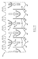
- Figure 4 illustrates a plurality of the wall portions 20 of a strip 16, each of these wall portions 20 being adapted to delimit two cells 18, one on each side of the strip 16.
- the coolant flows upwardly through each cell 18 in the flow direction F represented on Figure 4 from an upstream lower edge 26 to a downstream upper edge 28 of the strip 16.
- the flow direction F is parallel to the cell axis A.
- Each wall portion 20 extends from the lower edge 26 to the upper edge 28.
- the wall portions 20 are separated by slits 30 provided on the lower edge 26 and extending substantially to the half-height of the strip 16 for engagement with a series of corresponding slits 30 provided on the upper edge 28 and extending substantially to the half-height of an intersecting strip 16.
- the strip 16 optionally comprises fins 32 protruding upwardly from the upper edge 28, each fin 32 being inclined relative to the cell axis A for imparting helical motion to the coolant fluid flowing through the cells 18 and enhancing heat exchange between the coolant and the fuel rods 4.
- the strip 16 comprises on each of the illustrated wall portions 20 a spring 22, a dimple 24 and a motion limiter 34 each formed in the strip 16 and thus being integrally one-piece with the strip 16.
- each wall portion 20 protrude on the same face of the strip 16, whereas the dimple 24 protrudes on the opposite face of the strip 16.
- the dimples 24 are alternately disposed below and above the springs 22 on the adjacent wall portions 20. Interlaced strips 16 thus can be arranged such that a spring 22 provided on a wall portion 20 of a strip 16 delimiting a cell 18 faces a dimple 24 provided on the opposite wall portion 20 of another strip 16 delimiting the cell 18.
- the springs 22 of the strip 16 are identical and one spring 22 is further described with reference to Figures 5-7 .
- the spring 22 illustrated on Figure 5 comprises a flexible cantilevered tab 36 and a contact portion 38 cut out in the strip 16.
- the tab 36 is delimited in the strip 16 by an elongated curved slot 40 of closed contour.
- the tab 36 is delimited between the slot 40 and the connection line 46 joining the opposed ends 48 of the slot 40.
- the ends 48 are preferably circular and enlarged to limit mechanical local peak stresses.
- the line 46 is perpendicular to the cell axis A.
- the tab 36 is connected to the wall portion 20 along the line 46.
- the tab 36 extends downwardly in cantilevered fashion towards the upstream lower edge 26 and has an upper base 42 connected to the wall portion 20 and a lower free tip 44.
- the tab 36 is converging towards the free tip 44.
- the slot 40 is generally U-shape with diverging branches (or V-shape with a rounded tip).
- the tab 36 In a free state of the spring 22, the tab 36 is inclined relative to the wall portion 20 and extends downwardly and away from the wall portion 20 towards the center of the cell 18 delimited by the wall portion 20.
- the tab 36 is elastically flexible by elastic deformation of the tab 36 with rotation of the tab 36 around a rotation axis substantially coinciding with the line 46. The flexibility of the tab can be adjusted by adjusting the diameter of the ends 48 of the slot 40.
- the contact portion 38 is formed exclusively in the tab 36 and protrudes from the tab 36 opposite the wall portion 20 and towards the center of a cell 18 delimited by the wall portion 20.
- the contact portion 38 is integrally one-piece with the tab 36.
- the contact portion 38 is provided in the form of an arched bridge cut out in the tab 36.
- the contact portion 38 is elongated in the direction of the cell axis A, the two ends of the contact portion 38 connected to the tab 36 being aligned in the direction of the cell axis A.
- the contact portion 38 is formed as a lancing delimited between two openings 52 extending substantially parallel to each other in the direction of the cell axis A.
- the motion limiter 34 associated to the spring 22 is formed in the strip 16 at a distance from the spring 22 and protrudes from the wall portion 20 on the same side than the corresponding spring 22.
- the motion limiter 34 is a bulge of curved perimeter formed in the strip 16, for instance of circular perimeter as illustrated on Figure 5 with a risen portion 56 and an apex 62.
- the motion limiter 34 is disposed below or above the corresponding spring 22 ( Figure 3 ).
- the contact portion 38 contacts the outer surface of a fuel rod 4 extending through a cell 18 delimited by the wall portion 20 with the tab 36 being elastically deformed towards the wall portion 20.
- the spring 22 thus biases the fuel rod 4 away from the wall portion 20 (toward the right on Figure 7 ) in contact with a dimple 24 provided on the opposite wall portion 20 delimiting the cell 18.
- the free tip 44 of the tab 36 extends substantially in the plane of the wall portion 20 and the height H of the contact portion 38 relative to the wall portion 20 is superior to the height h of the apex 62 of the motion limiter 34.
- the coolant flows through the cell 18 and around the fuel rod 4 upwardly at high speed in the flow direction F parallel to the cell axis A. This causes transverse vibration of the fuel rod 4 inside the cell 18. Transverse vibrations may also occur during transportation from manufacturing plant to power plant and during handling of the fuel assembly 2.
- the motion limiter 34 is rigid and limits movements of a fuel rod 4 towards the wall portion 20 against the action of the spring 22.
- the motion limiter 34 thus avoids overstress of the spring 22 and namely plastic deformation thereof.
- the spring 22 formed in the strip 16 with a flexible cantilevered tab 36 and a rigid contact portion 38 enables to bias the fuel rod 4 with an appropriate transverse force while limiting the flow resistance.
- the tab 36 furnishes the biasing force when the free tip 44 of the tab 36 is retracted in the plane (or nearly) of the wall portion 20; in this position only the contact portion 38 protrudes from the wall portion 20.
- the contact portion 38 being elongated in the flow direction F enables to further limit the flow resistance and to provide an elongated contact zone with the fuel rod 4 for limiting fretting risks.
- the spring 22 including the tab 36 and the contact portion 38 is obtainable in a single stamping operation easily and at low cost.
- Figures 8 and 9 differs from that of Figure 5 and 6 by the feature that the contact portion 38 is formed partially in the tab 36 and partially in the wall portion 20.
- the contact portion 38 is more elongated and steps over the line 46 joining the ends 48 of the slot 40 delimiting the tab 36.
- the motion limiter 34 is a bulge having an elliptical perimeter.
- the motion limiter 34 is elongated transversely to the flow direction F.
- Each motion limiter 34 is located above the corresponding spring 22 in line with the spring 22 in the flow direction.
- Each motion limiter 34 is located adjacent the base of the spring tab 36.
- the motion limiter 34 is tangent to the connection line 46.
- the contact portion 38 is provided in the form of a closed bulge of curved perimeter. As illustrated on Figure 10 , the perimeter is advantageously an elliptical perimeter preferably elongated in the flow direction F.
- the dimples 24 are also provided in the form of bulges of elliptical perimeter elongated in the flow direction.
- the motion limiter 34 of Figure 10 is combined with a spring 22 having a bridge-like contact portion 38 cut in the spring as in Figures 4-6 .
- the motion limiter 34 of circular perimeter of Figures 4-6 is combined with the contact portion of Figure 10 in the form of a closed bulge, namely of elliptical perimeter.
- the motion limiter 34 and the spring 22 provided in line, one upstream the other in the flow direction F, reduce flow resistance of the strip 16.
- the motion limiter 34 located above the spring 22 adjacent the connection line 46 stiffens the spring element 22 and lead to less local peak stresses at the ends 48 of the slot 40. These effects are even increased with the motion limiter 34 of elliptical perimeter of Figure 10 .
- the upstream lower edge 26 of the strip 16 is zigzag-shaped such that it is low at the center of each wall portion 20 and high at the junction between the wall portions 20 where interlaced strips 16 intersect each other.
- a spacer grid 14 may be formed with interlaced strips 16 crossing at cross points 66 at a level higher than the lower points 64, whereby debris possibly present in the coolant fluid are guided transversely towards the cross points 66 at corners of the square shaped cells 18 where the space between the inner surface of the cells 18 and the fuel rods 4 is larger. The debris are thus prevented from damaging the fuel rods 4.
- the lower edge 26 of the strip 16 is zigzag-shaped such that the upstream lower edge 26 is alternatively at a high level and at a low level at the junction between the wall portions 20.
- the interlaced strips 16 may be assembled to provide cross points 66 at a high level and cross points 66 at a low level arranged in staggered rows, with the same benefit.
- the lower edge 26 may present a wave shape instead of a zigzag shape.
- the invention is applicable to spacer grids for a PWR (Pressurized Water Reactor) fuel assembly or to spacer grids for a BWR (Boiling Water Reactor) fuel assembly as illustrated and also to spacer grids for a VVER (Water-Water Energetic Reactor) fuel assembly.
- PWR Pressure Water Reactor
- BWR Biting Water Reactor
- VVER Water-Water Energetic Reactor
Landscapes
- Physics & Mathematics (AREA)
- Engineering & Computer Science (AREA)
- Plasma & Fusion (AREA)
- General Engineering & Computer Science (AREA)
- High Energy & Nuclear Physics (AREA)
- Fuel Cell (AREA)
- Monitoring And Testing Of Nuclear Reactors (AREA)
Priority Applications (11)
| Application Number | Priority Date | Filing Date | Title |
|---|---|---|---|
| EP11305628A EP2525366A1 (de) | 2011-05-20 | 2011-05-20 | Streifen für ein Abstandsgitter eines Kernbrennstoffbündels |
| KR1020137033628A KR20140033435A (ko) | 2011-05-20 | 2012-05-18 | 핵 연료 조립체 스페이서 그리드를 위한 스트립 |
| PCT/EP2012/059306 WO2012160003A1 (en) | 2011-05-20 | 2012-05-18 | Strip for a nuclear fuel assembly spacer grid |
| JP2014510830A JP6296976B2 (ja) | 2011-05-20 | 2012-05-18 | 核燃料集合体のスペーサグリッド用の帯板 |
| ES15161691.9T ES2622389T3 (es) | 2011-05-20 | 2012-05-18 | Banda para una rejilla espaciadora de conjunto de combustible nuclear |
| EP15161691.9A EP2913824B1 (de) | 2011-05-20 | 2012-05-18 | Streifen für ein abstandsgitter eines kernbrennstoffbündels |
| CN201280024558.2A CN103563005B (zh) | 2011-05-20 | 2012-05-18 | 用于核燃料组件定位格架的条带 |
| EP12723162.9A EP2710604B1 (de) | 2011-05-20 | 2012-05-18 | Streifen für ein abstandsgitter eines kernbrennstabbündels |
| US13/822,510 US9953730B2 (en) | 2011-05-20 | 2012-05-18 | Strip for a nuclear fuel assembly spacer grid |
| ES12723162.9T ES2548840T3 (es) | 2011-05-20 | 2012-05-18 | Tira para una rejilla separadora de elementos de combustible nuclear |
| JP2017231539A JP6448750B2 (ja) | 2011-05-20 | 2017-12-01 | 核燃料集合体のスペーサグリッド用の帯板 |
Applications Claiming Priority (1)
| Application Number | Priority Date | Filing Date | Title |
|---|---|---|---|
| EP11305628A EP2525366A1 (de) | 2011-05-20 | 2011-05-20 | Streifen für ein Abstandsgitter eines Kernbrennstoffbündels |
Publications (1)
| Publication Number | Publication Date |
|---|---|
| EP2525366A1 true EP2525366A1 (de) | 2012-11-21 |
Family
ID=46148858
Family Applications (3)
| Application Number | Title | Priority Date | Filing Date |
|---|---|---|---|
| EP11305628A Withdrawn EP2525366A1 (de) | 2011-05-20 | 2011-05-20 | Streifen für ein Abstandsgitter eines Kernbrennstoffbündels |
| EP12723162.9A Active EP2710604B1 (de) | 2011-05-20 | 2012-05-18 | Streifen für ein abstandsgitter eines kernbrennstabbündels |
| EP15161691.9A Active EP2913824B1 (de) | 2011-05-20 | 2012-05-18 | Streifen für ein abstandsgitter eines kernbrennstoffbündels |
Family Applications After (2)
| Application Number | Title | Priority Date | Filing Date |
|---|---|---|---|
| EP12723162.9A Active EP2710604B1 (de) | 2011-05-20 | 2012-05-18 | Streifen für ein abstandsgitter eines kernbrennstabbündels |
| EP15161691.9A Active EP2913824B1 (de) | 2011-05-20 | 2012-05-18 | Streifen für ein abstandsgitter eines kernbrennstoffbündels |
Country Status (7)
| Country | Link |
|---|---|
| US (1) | US9953730B2 (de) |
| EP (3) | EP2525366A1 (de) |
| JP (2) | JP6296976B2 (de) |
| KR (1) | KR20140033435A (de) |
| CN (1) | CN103563005B (de) |
| ES (2) | ES2548840T3 (de) |
| WO (1) | WO2012160003A1 (de) |
Families Citing this family (5)
| Publication number | Priority date | Publication date | Assignee | Title |
|---|---|---|---|---|
| US9881701B2 (en) | 2012-04-17 | 2018-01-30 | Bwxt Mpower, Inc. | Spacer grids with springs having improved robustness |
| CN104318962B (zh) * | 2014-10-16 | 2017-07-14 | 岭澳核电有限公司 | 具有流线型低压降流道的定位格架及燃料组件 |
| CN105869681B (zh) * | 2016-05-26 | 2018-03-20 | 中广核研究院有限公司 | 燃料组件及其无外条带定位格架和条带 |
| CN107230502A (zh) * | 2017-06-09 | 2017-10-03 | 岭东核电有限公司 | 燃料组件及其格架和支撑插入件 |
| EP4016547A1 (de) * | 2020-12-21 | 2022-06-22 | Framatome | Abstandsgitterelement eines abstandsgitters für kernbrennstabbündel, abstandsgitter und kernbrennstabbündel |
Citations (5)
| Publication number | Priority date | Publication date | Assignee | Title |
|---|---|---|---|---|
| US3844887A (en) * | 1968-09-12 | 1974-10-29 | Westinghouse Electric Corp | Nuclear reactor fuel assembly |
| US4058436A (en) * | 1975-12-05 | 1977-11-15 | Combustion Engineering Inc. | Nuclear reactor seismic fuel assembly grid |
| US4163690A (en) * | 1977-01-07 | 1979-08-07 | The Babcock & Wilcox Company | Nuclear reactor fuel assembly spacer grid |
| GB2181292A (en) * | 1985-10-04 | 1987-04-15 | Westinghouse Electric Corp | Nuclear reactor spacer grid and ductless core component |
| US4879090A (en) | 1987-08-24 | 1989-11-07 | Combustion Engineering, Inc. | Split vaned nuclear fuel assembly grid |
Family Cites Families (24)
| Publication number | Priority date | Publication date | Assignee | Title |
|---|---|---|---|---|
| JPS554533A (en) * | 1978-06-27 | 1980-01-14 | Tokyo Shibaura Electric Co | Grid spacer |
| FR2465297A1 (fr) | 1979-09-07 | 1981-03-20 | Commissariat Energie Atomique | Grille d'espacement pour elements combustibles de reacteurs nucleaires |
| US4426355A (en) * | 1982-01-04 | 1984-01-17 | Combustion Engineering, Inc. | Spacer grid for nuclear fuel assembly |
| JPS61108997U (de) * | 1984-12-21 | 1986-07-10 | ||
| US4702881A (en) | 1985-04-02 | 1987-10-27 | Westinghouse Electric Corp. | Nuclear reactor spacer grid |
| JPS62148891A (ja) | 1985-12-24 | 1987-07-02 | 株式会社日立製作所 | 電磁フロ−ダイオ−ド |
| FR2616577B1 (fr) | 1987-06-09 | 1991-02-15 | Framatome Sa | Grille-entretoise pour un assemblage combustible d'un reacteur nucleaire a eau legere |
| JPH01173898A (ja) | 1987-09-10 | 1989-07-10 | Mitsubishi Nuclear Fuel Co Ltd | 原子炉燃料集合体の支持格子 |
| JPH067190B2 (ja) | 1988-03-24 | 1994-01-26 | 三菱原子燃料株式会社 | 支持格子 |
| JPH0221597A (ja) * | 1988-07-11 | 1990-01-24 | Hitachi Medical Corp | X線装置 |
| JPH0221597U (de) * | 1988-07-29 | 1990-02-13 | ||
| JPH02257092A (ja) | 1989-03-30 | 1990-10-17 | Nuclear Fuel Ind Ltd | リング素子型燃料スペーサ |
| FR2666678B1 (fr) | 1990-07-24 | 1993-07-30 | Framatome Sa | Grille a ailettes de melange pour assemblage combustible nucleaire. |
| SE468110B (sv) * | 1991-03-13 | 1992-11-02 | Asea Atom Ab | Spridare foer sammanhaallande av braenslestavar i en kaernreaktors braenslepatron |
| US5331678A (en) | 1993-04-27 | 1994-07-19 | Combustion Engineering, Inc. | Spacer grid rod support system |
| FR2736190B1 (fr) | 1995-06-29 | 1997-10-10 | Framatome Sa | Grille-entretoise d'un assemblage de combustible pour un reacteur nucleaire et assemblage de combustible |
| US6526116B1 (en) | 1997-07-02 | 2003-02-25 | Westinghouse Electric Company Llc | Nuclear fuel assembly with hydraulically balanced mixing vanes |
| FR2766003B1 (fr) | 1997-07-11 | 1999-12-03 | Framatome Sa | Grille pour assemblage combustible nucleaire et plaquette pour une telle grille |
| KR100330358B1 (ko) | 1999-07-29 | 2002-04-01 | 장인순 | 냉각수 혼합을 위한 딤플형 베인과 다중스프링이 부착된 지지격자체 |
| KR100432581B1 (ko) | 2001-07-10 | 2004-05-24 | 한국수력원자력 주식회사 | 연료봉 접촉면적과 스프링 탄성영역을 확장하는 격자스프링이 부착된 지지격자체 |
| US6819733B2 (en) | 2002-05-15 | 2004-11-16 | Westinghouse Electric Company Llc | Fuel assembly and associated grid for nuclear reactor |
| KR20070102001A (ko) | 2006-04-13 | 2007-10-18 | 한국원자력연구원 | 연료봉과 등각 접촉면적을 증가시키는 지지격자 스프링 |
| FR2910687B1 (fr) | 2006-12-26 | 2016-08-26 | Areva Np | Grille-entretoise a elements d'appui en forme de selle de cheval et assemblage de combustible nucleaire correspondant. |
| EP2525363A1 (de) | 2011-05-20 | 2012-11-21 | Areva NP | Streifen für ein Abstandsgitter eines Kernbrennstoffbündels |
-
2011
- 2011-05-20 EP EP11305628A patent/EP2525366A1/de not_active Withdrawn
-
2012
- 2012-05-18 EP EP12723162.9A patent/EP2710604B1/de active Active
- 2012-05-18 EP EP15161691.9A patent/EP2913824B1/de active Active
- 2012-05-18 KR KR1020137033628A patent/KR20140033435A/ko not_active Withdrawn
- 2012-05-18 US US13/822,510 patent/US9953730B2/en active Active
- 2012-05-18 JP JP2014510830A patent/JP6296976B2/ja not_active Expired - Fee Related
- 2012-05-18 ES ES12723162.9T patent/ES2548840T3/es active Active
- 2012-05-18 ES ES15161691.9T patent/ES2622389T3/es active Active
- 2012-05-18 CN CN201280024558.2A patent/CN103563005B/zh active Active
- 2012-05-18 WO PCT/EP2012/059306 patent/WO2012160003A1/en not_active Ceased
-
2017
- 2017-12-01 JP JP2017231539A patent/JP6448750B2/ja active Active
Patent Citations (5)
| Publication number | Priority date | Publication date | Assignee | Title |
|---|---|---|---|---|
| US3844887A (en) * | 1968-09-12 | 1974-10-29 | Westinghouse Electric Corp | Nuclear reactor fuel assembly |
| US4058436A (en) * | 1975-12-05 | 1977-11-15 | Combustion Engineering Inc. | Nuclear reactor seismic fuel assembly grid |
| US4163690A (en) * | 1977-01-07 | 1979-08-07 | The Babcock & Wilcox Company | Nuclear reactor fuel assembly spacer grid |
| GB2181292A (en) * | 1985-10-04 | 1987-04-15 | Westinghouse Electric Corp | Nuclear reactor spacer grid and ductless core component |
| US4879090A (en) | 1987-08-24 | 1989-11-07 | Combustion Engineering, Inc. | Split vaned nuclear fuel assembly grid |
Also Published As
| Publication number | Publication date |
|---|---|
| JP6448750B2 (ja) | 2019-01-09 |
| WO2012160003A1 (en) | 2012-11-29 |
| US20140056398A1 (en) | 2014-02-27 |
| EP2710604B1 (de) | 2015-07-01 |
| CN103563005A (zh) | 2014-02-05 |
| JP2014519033A (ja) | 2014-08-07 |
| ES2548840T3 (es) | 2015-10-21 |
| JP6296976B2 (ja) | 2018-03-20 |
| EP2710604A1 (de) | 2014-03-26 |
| US9953730B2 (en) | 2018-04-24 |
| KR20140033435A (ko) | 2014-03-18 |
| EP2913824B1 (de) | 2017-02-01 |
| EP2913824A1 (de) | 2015-09-02 |
| CN103563005B (zh) | 2016-06-01 |
| ES2622389T3 (es) | 2017-07-06 |
| JP2018028557A (ja) | 2018-02-22 |
Similar Documents
| Publication | Publication Date | Title |
|---|---|---|
| EP2710600B1 (de) | Streifen für ein abstandsgitter eines kernbrennstoffbündels | |
| EP1868208B1 (de) | Kernbrennstab-Abstandhalter mit Trümmerführungsvorrichtung | |
| EP2913824B1 (de) | Streifen für ein abstandsgitter eines kernbrennstoffbündels | |
| US6421407B1 (en) | Nuclear fuel spacer grid with dipper vanes | |
| KR20010011647A (ko) | 냉각수 혼합을 위한 딤플형 베인과 다중스프링이 부착된 지지격자체 | |
| EP2710605B1 (de) | Abstandsgitter für kernbrennstabbbündel und zugehöriges kernbrennstabbündel | |
| EP1416500B1 (de) | Doppelwandige, düsenartige, seitengeschlitzte Abstandshalter für Kernbrennstabbündel | |
| US9196386B2 (en) | Spacer grid for nuclear fuel assembly for reducing high frequency vibration | |
| TW201312588A (zh) | 一種用於核燃料組件分隔柵之條片構件 | |
| US6272197B1 (en) | Coolant mixing grid for nuclear fuel assembly | |
| KR101071286B1 (ko) | 내부 격자판의 교차영역에서 핵연료봉을 지지하며 상하로 이동가능한 탄성 지지판이 삽입된 지지격자체 |
Legal Events
| Date | Code | Title | Description |
|---|---|---|---|
| PUAI | Public reference made under article 153(3) epc to a published international application that has entered the european phase |
Free format text: ORIGINAL CODE: 0009012 |
|
| AK | Designated contracting states |
Kind code of ref document: A1 Designated state(s): AL AT BE BG CH CY CZ DE DK EE ES FI FR GB GR HR HU IE IS IT LI LT LU LV MC MK MT NL NO PL PT RO RS SE SI SK SM TR |
|
| AX | Request for extension of the european patent |
Extension state: BA ME |
|
| STAA | Information on the status of an ep patent application or granted ep patent |
Free format text: STATUS: THE APPLICATION IS DEEMED TO BE WITHDRAWN |
|
| 18D | Application deemed to be withdrawn |
Effective date: 20130522 |