EP2525231A1 - Method and device for monitoring a liquid metering procedure using cylinder stroke pipettes - Google Patents

Method and device for monitoring a liquid metering procedure using cylinder stroke pipettes Download PDF

Info

Publication number
EP2525231A1
EP2525231A1 EP11168004A EP11168004A EP2525231A1 EP 2525231 A1 EP2525231 A1 EP 2525231A1 EP 11168004 A EP11168004 A EP 11168004A EP 11168004 A EP11168004 A EP 11168004A EP 2525231 A1 EP2525231 A1 EP 2525231A1
Authority
EP
European Patent Office
Prior art keywords
pipette
pipette tip
neck
actuator
volume
Prior art date
Legal status (The legal status is an assumption and is not a legal conclusion. Google has not performed a legal analysis and makes no representation as to the accuracy of the status listed.)
Withdrawn
Application number
EP11168004A
Other languages
German (de)
French (fr)
Inventor
Bernhard Brinkhaus
Current Assignee (The listed assignees may be inaccurate. Google has not performed a legal analysis and makes no representation or warranty as to the accuracy of the list.)
Brinkhaus Management GmbH
Ymatron AG
Original Assignee
Brinkhaus Management GmbH
Ymatron AG
Priority date (The priority date is an assumption and is not a legal conclusion. Google has not performed a legal analysis and makes no representation as to the accuracy of the date listed.)
Filing date
Publication date
Application filed by Brinkhaus Management GmbH, Ymatron AG filed Critical Brinkhaus Management GmbH
Priority to PCT/EP2012/059214 priority Critical patent/WO2012156492A1/en
Publication of EP2525231A1 publication Critical patent/EP2525231A1/en
Withdrawn legal-status Critical Current

Links

Images

Classifications

    • GPHYSICS
    • G01MEASURING; TESTING
    • G01NINVESTIGATING OR ANALYSING MATERIALS BY DETERMINING THEIR CHEMICAL OR PHYSICAL PROPERTIES
    • G01N35/00Automatic analysis not limited to methods or materials provided for in any single one of groups G01N1/00 - G01N33/00; Handling materials therefor
    • G01N35/10Devices for transferring samples or any liquids to, in, or from, the analysis apparatus, e.g. suction devices, injection devices
    • G01N35/1009Characterised by arrangements for controlling the aspiration or dispense of liquids
    • BPERFORMING OPERATIONS; TRANSPORTING
    • B01PHYSICAL OR CHEMICAL PROCESSES OR APPARATUS IN GENERAL
    • B01LCHEMICAL OR PHYSICAL LABORATORY APPARATUS FOR GENERAL USE
    • B01L3/00Containers or dishes for laboratory use, e.g. laboratory glassware; Droppers
    • B01L3/02Burettes; Pipettes
    • B01L3/021Pipettes, i.e. with only one conduit for withdrawing and redistributing liquids
    • B01L3/0217Pipettes, i.e. with only one conduit for withdrawing and redistributing liquids of the plunger pump type
    • B01L3/0237Details of electronic control, e.g. relating to user interface
    • GPHYSICS
    • G01MEASURING; TESTING
    • G01FMEASURING VOLUME, VOLUME FLOW, MASS FLOW OR LIQUID LEVEL; METERING BY VOLUME
    • G01F23/00Indicating or measuring liquid level or level of fluent solid material, e.g. indicating in terms of volume or indicating by means of an alarm
    • G01F23/22Indicating or measuring liquid level or level of fluent solid material, e.g. indicating in terms of volume or indicating by means of an alarm by measuring physical variables, other than linear dimensions, pressure or weight, dependent on the level to be measured, e.g. by difference of heat transfer of steam or water
    • G01F23/28Indicating or measuring liquid level or level of fluent solid material, e.g. indicating in terms of volume or indicating by means of an alarm by measuring physical variables, other than linear dimensions, pressure or weight, dependent on the level to be measured, e.g. by difference of heat transfer of steam or water by measuring the variations of parameters of electromagnetic or acoustic waves applied directly to the liquid or fluent solid material
    • G01F23/296Acoustic waves
    • G01F23/2966Acoustic waves making use of acoustical resonance or standing waves
    • GPHYSICS
    • G01MEASURING; TESTING
    • G01NINVESTIGATING OR ANALYSING MATERIALS BY DETERMINING THEIR CHEMICAL OR PHYSICAL PROPERTIES
    • G01N35/00Automatic analysis not limited to methods or materials provided for in any single one of groups G01N1/00 - G01N33/00; Handling materials therefor
    • G01N35/10Devices for transferring samples or any liquids to, in, or from, the analysis apparatus, e.g. suction devices, injection devices
    • G01N35/1009Characterised by arrangements for controlling the aspiration or dispense of liquids
    • G01N35/1016Control of the volume dispensed or introduced
    • BPERFORMING OPERATIONS; TRANSPORTING
    • B01PHYSICAL OR CHEMICAL PROCESSES OR APPARATUS IN GENERAL
    • B01LCHEMICAL OR PHYSICAL LABORATORY APPARATUS FOR GENERAL USE
    • B01L2200/00Solutions for specific problems relating to chemical or physical laboratory apparatus
    • B01L2200/14Process control and prevention of errors
    • B01L2200/143Quality control, feedback systems
    • BPERFORMING OPERATIONS; TRANSPORTING
    • B01PHYSICAL OR CHEMICAL PROCESSES OR APPARATUS IN GENERAL
    • B01LCHEMICAL OR PHYSICAL LABORATORY APPARATUS FOR GENERAL USE
    • B01L2400/00Moving or stopping fluids
    • B01L2400/04Moving fluids with specific forces or mechanical means
    • B01L2400/0403Moving fluids with specific forces or mechanical means specific forces
    • B01L2400/0433Moving fluids with specific forces or mechanical means specific forces vibrational forces

Landscapes

  • Physics & Mathematics (AREA)
  • General Physics & Mathematics (AREA)
  • Chemical & Material Sciences (AREA)
  • Health & Medical Sciences (AREA)
  • Biochemistry (AREA)
  • General Health & Medical Sciences (AREA)
  • Thermal Sciences (AREA)
  • Life Sciences & Earth Sciences (AREA)
  • Electromagnetism (AREA)
  • Analytical Chemistry (AREA)
  • Acoustics & Sound (AREA)
  • Fluid Mechanics (AREA)
  • Immunology (AREA)
  • Pathology (AREA)
  • Engineering & Computer Science (AREA)
  • Human Computer Interaction (AREA)
  • Clinical Laboratory Science (AREA)
  • Chemical Kinetics & Catalysis (AREA)
  • Devices For Use In Laboratory Experiments (AREA)
  • Sampling And Sample Adjustment (AREA)

Abstract

The device has a tubular actuator (9) designed for generating excitation angular frequency in a specific range. A pipette tip (2) of a piston-stroke pipette is designed as a part of a Helmholtz-resonator (13). The tip has a neck-shaped section (2c) with a pipette neck length (L), where the section opens into a pipette tip opening (2d) with a cross-sectional area. The tip and the pipette form a common volume (V). A control device (11) detects a change of resonance angular frequency of the resonator. An independent claim is also included for a method for detecting pipette volume and/or immersion of piston-stroke pipette into liquid.

Description

Die Erfindung betrifft eine Vorrichtung sowie ein Verfahren zur Überwachung eines Flüssigkeitsdosierungsvorgangs bei Kolbenhubpipetten sowie eine Pipettenspitze für eine derartige Vorrichtung sowie ein derartiges Verfahren.The invention relates to a device and a method for monitoring a liquid metering process in Kolbenhubpipetten and a pipette tip for such a device and such a method.

Stand der TechnikState of the art

Insbesondere elektronische Kolbenhubpipettiersysteme haben sich in den letzten Jahren in ihrer Form und Gestaltung nicht besonders verändert und sind kaum neuen Umgebungsbedingungen angepasst worden. Bekannte Kolbenhubpipettiersysteme haben üblicherweise eine Anordnung, wie diese in den Figuren 1a und 1b dargestellt ist. Die Kolbenhubpipette 1 umfasst eine Pipettenspitze 2, ein Pipettengehäuse 3 sowie einen innerhalb des Pipettengehäuses 3 in Richtung K verschiebbaren Kolben 4. Möglichen Fehlereinflüsse beim Pipettieren können sehr unterschiedliche Auswirkungen haben, von denen die wichtigsten folgenden Einfluss haben:

  • Wenn die Kolbenhubpipette tropft liegt eine Undichtigkeit vor. Die Ursache dieser Undichtigkeit kann in einer losen Pipettenspitze, in einer ungeeigneten Pipettenspitze, in einem zerkratzten Arbeitskonus oder in sonstigen defekten Dichtungen liegen. Solche Fehler sind sehr gravierend und treten relativ häufig auf, und zwar bis zu 50%. Die durch alle anderen Einflüsse verursachten Fehler, wie ungleicher Kraftverlauf, Temperaturunterschiede, Luftfeuchtigkeit und der barometrische Druck liegen im kleinen einstelligen Prozentbereich.
  • Die Druckschrift DE 101 48 608 offenbart ein Verfahren sowie eine Vorrichtung zur Überwachung des Flüssigkeitsdosierungsvorganges bei Kolbenhubpipetten. Bei dieser bekannten Vorrichtung wird ein Drucksensor verwendet, der bei Anhebung des Kolbens den Druckverlauf während des Pipettierens im Immenraum der Kolbenhubpipette beziehungsweise in deren Volumen V anzeigt. Diese bekannte Vorrichtung kann zwar grobe Undichtigkeiten detektieren, weist jedoch eine gewisse Fehleranfälligkeit auf, und kann z.B. auch nicht unterscheiden, ob Schaum oder Luft ansaugt werden.
In particular, electronic Kolbenhubpipettiersysteme have not changed significantly in recent years in their shape and design and have hardly been adapted to new environmental conditions. Known Kolbenhubpettettiersysteme usually have an arrangement such as this in the FIGS. 1a and 1b is shown. The piston stroke pipette 1 comprises a pipette tip 2, a pipette housing 3 and a piston 4 which can be displaced in the direction K in the pipette housing 3. Possible influences during pipetting can have very different effects, the most important of which have the following effects:
  • If the piston pipette drips, there is a leak. The cause of this leak may be in a loose pipette tip, in an improper pipette tip, in a scratched working cone, or in other defective seals. Such errors are very serious and occur relatively frequently, up to 50%. The errors caused by all other influences, such as uneven force, temperature differences, humidity and the barometric pressure are in the small single-digit percentage range.
  • The publication DE 101 48 608 discloses a method and a device for monitoring the liquid metering process in Kolbenhubpipetten. In this known device, a pressure sensor is used, which indicates the pressure curve during pipetting in the Immenraum the piston stroke pipette or in the volume V when raising the piston. Although this known device can detect gross leaks, but has a certain susceptibility to errors, and can not, for example, do not distinguish whether foam or air are sucked.

Darstellung der ErfindungPresentation of the invention

Es ist Aufgabe der vorliegenden Erfindung die Zuverlässigkeit des Flüssigkeitsdosierungsvorgangs bei Kolbenhubpipetten zu verbessern, insbesondere indem die noch möglichen Fehler reduziert werden.It is an object of the present invention to improve the reliability of the Flüssigkeitsdosierungsvorgangs piston reciprocating pipettes, in particular by the still possible errors are reduced.

Diese Aufgabe wird gelöst mit einer Vorrichtung für Kolbenhubpipetten aufweisend die Merkmale von Anspruch 1. Die Unteransprüche 2 bis 8 betreffen weitere, vorteilhafte Ausführungsformen. Die Aufgabe wird weiter gelöst mit einem Verfahren zum Betrieb einer Kolbenhubpipette aufweisend die Merkmale von Anspruch 9. Die Unteransprüche 10 bis 12 betreffen weitere vorteilhafte Verfahrensschritte. Die Aufgabe wird weiter gelöst durch die Verwendung von Pipettenspitzen gemäss Anspruch 13.This object is achieved with a device for Kolbenhubpipetten having the features of claim 1. The dependent claims 2 to 8 relate to further advantageous Embodiments. The object is further achieved with a method for operating a Kolbenhubpipette having the features of claim 9. The dependent claims 10 to 12 relate to further advantageous method steps. The object is further achieved by the use of pipette tips according to claim 13.

Die Aufgabe wird insbesondere gelöst mit einer Vorrichtung für eine Kolbenhubpipette zum Erfassen eines Pipettiervolumens und/oder des Eintauchens in eine Flüssigkeit, umfassend eine Kolbenhubpipette mit einer Pipettenspitze, sowie umfassend einen Aktuator und eine Ansteuerungsvorrichtung, wobei die Pipettenspitze als Teil eines Helmholtz-Resonators ausgestaltet ist, indem die Pipettenspitze einen halsförmigen Abschnitt mit einer Pipettenhalslänge L aufweist, und indem der halsförmige Abschnitt in eine Pipettenspitzenöffnung mit Querschnittfläche A mündet, und wobei die Pipettenspitze und die Kolbenhubpipette ein gemeinsames Volumen V umschliessen, und wobei der Aktuator ausgestaltet ist zur Erzeugung einer Anregungskreisfrequenz ω im Bereich von ω = c A V L ,

Figure imgb0001
wobei c der Schallgeschwindigkeit entspricht, und wobei die Ansteuervorrichtung eine Änderung der Resonanzkreisfrequenz ω0 des Helmholtz-Resonators erfasst.The object is in particular achieved with a device for a piston stroke pipette for detecting a pipetting volume and / or immersion in a liquid, comprising a piston stroke pipette with a pipette tip, and comprising an actuator and a drive device, wherein the pipette tip is designed as part of a Helmholtz resonator in that the pipette tip has a neck-shaped portion with a pipette neck length L, and in that the neck-shaped portion opens into a pipette tip opening with cross-sectional area A, and wherein the pipette tip and the piston stroke pipette enclose a common volume V, and wherein the actuator is designed to generate an excitation ring frequency ω In the range of ω = c A V L .
Figure imgb0001
where c corresponds to the speed of sound, and wherein the drive device detects a change in the resonant circuit frequency ω 0 of the Helmholtz resonator.

Die Aufgabe wird zudem insbesondere gelöst mit einem Verfahren für eine Kolbenhubpipette zum Erfassen eines Pipettiervolumens und/oder des Eintauchens der Kolbenhubpipette in eine Flüssigkeit, wobei die Kolbenhubpipette eine Pipettenspitze umfasst, und wobei die Pipettenspitze als Teil eines Helmholtz-Resonators ausgestaltet ist, indem die Pipettenspitze einen halsförmigen Abschnitt mit einer Pipettenhalslänge L aufweist, und indem der halsförmige Abschnitt in eine Pipettenspitzenöffnung mit Querschnittfläche A mündet, und wobei die Pipettenspitze und die Kolbenhubpipette ein gemeinsames Volumen V umschliessen, und wobei das Volumen V mit einer Anregungskreisfrequenz ω im Bereich von ω = c A V L

Figure imgb0002
angeregt wird, und wobei eine Veränderung der Resonanzkreisfrequenz ω0 des Helmholtz-Resonators detektiert wird.The object is also achieved in particular with a method for a piston stroke pipette for detecting a pipetting volume and / or immersing the piston stroke pipette in a liquid, the piston stroke pipette comprising a pipette tip, and wherein the pipette tip is designed as part of a Helmholtz resonator by the pipette tip a neck-shaped portion having a pipette neck length L, and in that the neck-shaped portion in FIG a pipette tip opening opens with a cross-sectional area A, and wherein the pipette tip and the Kolbenhubpipette a common volume V enclose, and wherein the volume V with an excitation circuit frequency ω in the range of ω = c A V L
Figure imgb0002
is excited, and wherein a change in the resonance frequency ω 0 of the Helmholtz resonator is detected.

Die vorliegende Erfindung bezieht sich auf das Gebiet der elektronischen Messungen von physikalischen und geometrischen Grössen, wie z.B. Volumen, Dichtigkeit, Füllungsgrad und Dichte. Ebenfalls kann ein weites Gebiet von Zuständen gemessen werden. Es handelt sich um eine Integration von Sensoren, Auswerteelektronik und Aktuatoren. Dabei können die Materialzusammensetzung und die Geometrie des Kontrollsystems beliebig sein und nach den zu wandelnden physikalischen oder geometrischen Grössen angepasst werden.The present invention relates to the field of electronic measurements of physical and geometric quantities, e.g. Volume, density, degree of filling and density. Also, a wide range of conditions can be measured. It is an integration of sensors, evaluation electronics and actuators. The material composition and the geometry of the control system can be arbitrary and adapted to the physical or geometric variables to be converted.

Ein Ziel der vorliegenden Erfindung ist, mit einer Vorrichtung für Kolbenhubpipetten die heute häufig auftreten Fehlereinflüsse beim Pipettieren möglichst zu reduzieren oder ganz zu beseitigen. Insbesondere kann heute fast überhaupt nicht unterschieden werden, ob die Eintauchspitze rein in der zu pipettierenden Flüssigkeit eingetaucht ist, oder ob sie noch im Schaum auf der Oberfläche ist.An object of the present invention is to reduce as much as possible with a device for Kolbenhubpipetten today occur error effects during pipetting or eliminate completely. In particular, today it is almost impossible to distinguish whether the immersion tip is immersed purely in the liquid to be pipetted, or whether it is still in the foam on the surface.

Die erfindungsgemässe Vorrichtung weist zudem den Vorteil auf, dass durch die Verwendung von miniaturisierten elektrischen Komponenten und mechanischen Bauteilen es möglich ist die erforderliche Vorrichtung, insbesondere den Aktuator und gegebenenfalls den Sensor, so klein zu gestalten, dass diese sich in das Pipettiersystems integrieren beziehungsweise in die Kolbenhubpipette einbauen lassen, was bezüglich der erfindungsgemässen Vorrichtung den zusätzlichen Vorteil ergibt, dass die Anzahl Kolbenhubpipetten pro Fläche beträchtlich erhöht werden kann. Die heute eingesetzten Überwachungsdrucksensoren erfordern erheblichen Platz.The inventive device also has the advantage that it is possible by the use of miniaturized electrical components and mechanical components, the required device, in particular the actuator and optionally the sensor to make so small that they can be integrated into the pipetting or can be installed in the piston stroke pipette, which gives the additional advantage with respect to the inventive device that the number Kolbenhubpipetten per area can be increased considerably. The monitoring pressure sensors used today require considerable space.

Die erfindungsgemässe Vorrichtung für eine Kolbenhubpipette macht sich die physikalischen Eigenschaften eines Helmholtz-Resonators zu nutzen. Daher ist es erforderlich, dass die Kolbenhubpipette sowie deren Pipettenspitze derart ausgestaltet und gegenseitig angepasst angeordnet sind, dass diese einen Helmholtz-Resonator ausbilden. Die Pipettenspitze ist als Teil eines Helmholtz-Resonators ausgestaltet, indem die Pipettenspitze einen halsförmigen Abschnitt mit einer Pipettenhalslänge L aufweist, und indem der halsförmige Abschnitt in eine Pipettenspitzenöffnung mit Querschnittfläche A mündet. Die Pipettenspitze und die Kolbenhubpipette umschliessen ein gemeinsames Volumen V. Ein Helmholtz-Resonator weist eine ausgeprägte Resonanzfrequenz beziehungsweise Resonanzkreisfrequenz auf, wobei die Resonanzfrequenz unter anderem von der Querschnittfläche A und vom Volumen V abhängt. Ein Verschliessen der Querschnittfläche A beim Eintauchen der Pipettenspitze hat eine sprunghafte Änderung der Eigenresonanz zur Folge. Eine Veränderung des Volumen V hat ebenfalls eine Änderung der Eigenresonanz zur Folge, sodass es über die Bestimmung der Änderung der Eigenresonanz möglich ist das Eintauchen der Pipettierspitze in eine Flüssigkeit zu erfassen oder eine Pipettiervolumen zu erfassen.The device according to the invention for a piston-stroke pipette makes use of the physical properties of a Helmholtz resonator. Therefore, it is necessary that the Kolbenhubpipette and the pipette tip are designed and arranged mutually adapted so that they form a Helmholtz resonator. The pipette tip is designed as part of a Helmholtz resonator in that the pipette tip has a neck-shaped section with a pipette neck length L, and in that the neck-shaped section opens into a pipette tip opening with a cross-sectional area A. The pipette tip and the piston stroke pipette enclose a common volume V. A Helmholtz resonator has a pronounced resonant frequency or resonant circuit frequency, wherein the resonant frequency depends inter alia on the cross-sectional area A and the volume V. Closing the cross-sectional area A during immersion of the pipette tip results in a sudden change in the self-resonance. A change in the volume V also results in a change of the self-resonance, so that it is possible to detect the immersion of the pipette tip into a liquid or to detect a pipetting volume by determining the change of the self-resonance.

Kurze Beschreibung der ZeichnungenBrief description of the drawings

Die zur Erläuterung der Ausführungsbeispiele verwendeten Zeichnungen zeigen:
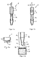
Fig. 1a
einen Längsschnitt durch eine bekannte Kolbenhubpipette;
Fig. 1b
einen Längsschnitt durch eine weitere bekannte Kolbenhubpipette;
Fig. 2a
ein Längsschnitt durch eine Pipettenspitze;
Fig. 2b
ein Längsschnitt durch eine Pipettenspitze sowie ein darunter angeordneter Flüssigkeitsbehälter;
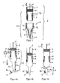
Fig. 3
einen Längsschnitt durch eine Kolbenhubpipette;
Fig. 4a bis 4c
Längsschnitte durch eine Kolbenhubpipette bei unterschiedlichen Verfahrenszuständen;
Fig. 5
einen Längsschnitt durch einen Aktuator;
Fig. 6
einen Längsschnitt durch einen Sensor;
Fig. 7a
einen Längsschnittes durch ein weiteres Ausführungsbeispiel eines im Pipettengehäuse angeordneten Aktuators;
Fig. 7b
eine Draufsicht auf den Aktuator von aussen;
Fig. 8
schematisch eine Ansicht eines Helmholtz-Resonators.
Grundsätzlich sind in den Zeichnungen gleiche Teile mit gleichen Bezugszeichen versehen.The drawings used to explain the embodiments show:
Fig. 1a
a longitudinal section through a known Kolbenhubpipette;
Fig. 1b
a longitudinal section through another known Kolbenhubpipette;
Fig. 2a
a longitudinal section through a pipette tip;
Fig. 2b
a longitudinal section through a pipette tip and a liquid container arranged thereunder;
Fig. 3
a longitudinal section through a piston stroke pipette;
Fig. 4a to 4c
Longitudinal sections through a piston stroke pipette at different process states;
Fig. 5
a longitudinal section through an actuator;
Fig. 6
a longitudinal section through a sensor;
Fig. 7a
a longitudinal section through a further embodiment of an actuator disposed in the pipette housing;
Fig. 7b
a plan view of the actuator from the outside;
Fig. 8
schematically a view of a Helmholtz resonator.
Basically, the same parts are given the same reference numerals in the drawings.

Wege zur Ausführung der ErfindungWays to carry out the invention

Fig. 8 zeigt schematisch eine Ansicht eines Helmholtz-Resonators 13 mit einem Hohlkörper 13c mit Volumen V, einem halsförmigen Abschnitt 13a mit Länge L und eine Öffnung 13b mit Querschnittsfläche A. Solch ein Helmholtz-Resonator ist ein Absorber, der aufgrund seines resonanten Verhaltens dem sich ausserhalb des Helmholtz-Resonators befindlichen Schallfeld Energie entzieht. Durch die Elastizität des Luftvolumens im Inneren des Hohlkörpers in Kombination mit der trägen Masse der sich im halsförmigen Abschnitt befindlichen Luft entsteht ein mechanisches Masse-Feder-System mit einer ausgeprägten Eigenresonanz. Ein Helmholtz-Resonator weist daher eine ausgeprägte Resonanzkreisfrequenz ω0 auf, welche sich wie folgt berechen lässt ω 0 = c A V L ,

Figure imgb0003
wobei c der Schallgeschwindigkeit entspricht. Fig. 8 schematically shows a view of a Helmholtz resonator 13 with a hollow body 13c with volume V, a neck-shaped Section 13a with a length L and an opening 13b with a cross-sectional area A. Such a Helmholtz resonator is an absorber which, due to its resonant behavior, deprives the sound field located outside the Helmholtz resonator of energy. Due to the elasticity of the air volume in the interior of the hollow body in combination with the inertial mass of the air located in the neck-shaped section, a mechanical mass-spring system with a pronounced natural resonance arises. A Helmholtz resonator therefore has a pronounced resonance frequency ω 0 , which can be calculated as follows ω 0 = c A V L .
Figure imgb0003
where c is the speed of sound.

Es wurde nun überraschenderweise erkannt, dass ein Helmholtz-Resonators 13 zur Überwachung eines
Flüssigkeitsdosierungsvorgangs bei Kolbenhubpipetten geeignet ist, wenn die Kolbenhubpipette und die Pipettenspitze derart gegenseitig ausgeformt werden, dass diese zusammen einen Helmholtz-Resonator 13 ausbilden, und wenn ein Aktuator verwendet wird, der das Volumen V im Helmholtz-Resonator 13 zum Schwingen anregt.
It has now surprisingly been found that a Helmholtz resonator 13 for monitoring a
Liquid metering operation is suitable in Kolbenhubpipetten when the Kolbenhubpipette and the pipette tip are formed such that they together form a Helmholtz resonator 13, and when an actuator is used, which stimulates the volume V in the Helmholtz resonator 13 to vibrate.

Die Figuren 2a und 2b zeigen je in einem Längsschnitt ein Ausführungsbeispiel einer Pipettenspitze 2 umfassend einen ersten
Abschnitt 2a sowie einen halsförmigen Abschnitt 2c, der eine Länge L aufweist und in eine Pipettenspitzenöffnung 2d mit Querschnittfläche A mündet. In den beiden dargestellten Ausführungsbeispielen ist der halsförmige Abschnitt 2c hohlzylinderförmig ausgestaltet. Der halsförmige Abschnitt 2c kann in einer Vielzahl von Möglichkeiten ausgestaltet sein, und könnte auch zum Beispiel gekrümmt verlaufen oder einen eckigen Innenquerschnitt, beispielsweise einen viereckigen Innenquerschnitt aufweisen. Die in Figur 2a dargestellte Pipettenspitze 2 umfasst zudem einen konisch verlaufenden Übergangsabschnitt 2b. Der Innenraum der Pipettenspitzen 2 bildet ein erstes Teilvolumen V1.
The FIGS. 2a and 2b each show in a longitudinal section an embodiment of a pipette tip 2 comprising a first
Section 2a and a neck-shaped portion 2c, which has a length L and opens into a pipette tip opening 2d with a cross-sectional area A. In the two illustrated embodiments, the neck-shaped portion 2c is configured as a hollow cylinder. The neck-shaped portion 2c can be configured in a variety of ways, and could also be curved, for example, or have an angular inner cross-section, for example a quadrangular one Have internal cross section. In the FIG. 2a illustrated pipette tip 2 also includes a conical transition section 2b. The interior of the pipette tips 2 forms a first partial volume V 1 .

Figur 3 zeigt in einem Längsschnitt eine Kolbenhubpipette 1, welche im Wesentlichen aus zwei Teilen besteht, einem Pipettengehäuse 3 mit darin in Richtung K verschiebbar gelagertem Kolben 4 mit Kolbenstange 5 und einer separaten Pipettenspitze 2, die ähnlich ausgestaltet ist wie bereits in Figur 2b dargestellt. Der Innenraum der Kolbenhubpipette 1 bildet ein zweites Teilvolumen V2. Die Pipettenspitze 2 kann, wie in Figur 4a dargestellt, auf das Pipettengehäuse 3 aufgesteckt werden, und ist vorzugsweise lösbar mit dem Pipettengehäuse 3 verbunden, vorzugsweise derart, dass zwischen der Pipettenspitze 2 und dem Pipettengehäuse 3 eine Fluid dichte Verbindung besteht. Die Pipettenspitze 2 und die Kolbenhubpipette 1 umschliessen somit ein gemeinsames Volumen V, wobei zusammen mit der Pipettenspitze 2 ein Helmholtz-Resonator 13 ausgebildet wird, mit einem halsförmigen Abschnitt 2c der Länge L und einer Austrittsöffnung 2d mit Querschnittfläche A. Die Kolbenhubpipette 1 könnte auch derart ausgestaltet sein, dass das Pipettengehäuse 3 fest und unlösbar mit der Pipettenspitze 2 verbunden ist, wobei das Pipettengehäuse 3 und die Pipettenspitze 2 auch gemeinsam aus einem einzigen Teil bestehen könnten und z.B. aus Glas oder einem Kunststoff gefertigt sind. FIG. 3 shows in a longitudinal section a Kolbenhubpipette 1, which consists essentially of two parts, a pipette housing 3 with it in the direction K displaceably mounted piston 4 with piston rod 5 and a separate pipette tip 2, which is designed similar to that already in FIG. 2b shown. The interior of the piston stroke pipette 1 forms a second partial volume V 2 . The pipette tip 2 can, as in FIG. 4a shown, are attached to the pipette housing 3, and is preferably detachably connected to the pipette housing 3, preferably such that there is a fluid-tight connection between the pipette tip 2 and the pipette housing 3. The pipette tip 2 and the piston stroke pipette 1 thus surround a common volume V, wherein a Helmholtz resonator 13 is formed together with the pipette tip 2, with a neck-shaped portion 2c of length L and an outlet opening 2d with cross-sectional area A. The piston stroke pipette 1 could also be so be configured such that the pipette housing 3 is firmly and permanently connected to the pipette tip 2, wherein the pipette housing 3 and the pipette tip 2 could also consist of a single part together and are made for example of glass or a plastic.

In den Figuren 3 sowie 4a bis 4c ist im Innenraum des Pipettengehäuses 3 ein als Schwingungserreger ausgestalteter Aktuator 9 angeordnet, um im gemeinsamen Volumen V eine Schwingung beziehungsweise eine Schallwelle zu erzeugen. Der Aktuator 9 ist aussen zylinderförmig ausgestaltet und liegt am Pipettengehäuse 3 an. Der Aktuator 9 ist innen sich konisch gegen unten erweiternd ausgestaltet. Im Pipettengehäuse 3 ist zudem ein Sensor 10 angeordnet, der ringförmig ausgestaltet ist und an dem Innenrand des Pipettengehäuses 3 anliegt. Der Aktuator 9 sowie der Sensor 10 sind über elektrische Leitungen 11a mit einer Ansteuervorrichtung 11 verbunden.In the Figures 3 and 4a to 4c is arranged in the interior of the pipette housing 3 designed as a vibration actuator actuator 9 to generate in the common volume V a vibration or a sound wave. Of the Actuator 9 is designed outside cylindrical and is located on the pipette housing 3 at. The actuator 9 is internally conically widening towards the bottom. In the pipette housing 3, a sensor 10 is also arranged, which is designed annular and rests against the inner edge of the pipette housing 3. The actuator 9 and the sensor 10 are connected via electrical lines 11a to a drive device 11.

Vorteilhafterweise wird, wie in Figur 4a dargestellt, am Volumen V ein sogenannter Schwingungserreger 9 angebracht, der sowohl seitlich als auch in Rohrbauform auf das Volumen V wirkt. Der Schwingungserreger 9 kann wie dargestellt in einer konusförmigen Ausführung mit dem Volumen V kombiniert werden, was zusätzlich ermöglicht den hydrostatischen Gegendruck der aufsteigenden Flüssigkeit zu messen.Advantageously, as in FIG. 4a represented on the volume V, a so-called vibration exciter 9 is mounted, which acts both on the side and in the pipe design on the volume V. The vibrator 9 can be combined as shown in a cone-shaped design with the volume V, which also allows to measure the hydrostatic back pressure of the rising liquid.

Das erfindungsgemässe Kontrollsystem für Kolbenhubpipettierungen liefert in dieser Art erstmalig Information über das exakte Eintauchen in die eigentliche Flüssigkeit, auch dann, wenn eine undefinierte Oberfläche mit sich darauf befindlichem Schaum vorliegt. In Figur 4a ist die Pipettieranordnung mit den einzelnen Komponenten dargestellt. In einer derartigen Konfiguration, bestehend aus dem Volumen V, dem Hals L und der Öffnung A der Pipettenspitze 2d kann man eine bis heute für Kolbenhubpipetten nicht angewendete physikalische Beziehung anwenden. Nach einer längeren Herleitung aus der Helmholztheorie erhält man die nachfolgende Beziehung zwischen der Kreisfrequenz ω, dem Volumen V, dem Pipettenspitzenhals mit Länge L und der Pipettenspitzenöffnung A: ω = c A V L .

Figure imgb0004
Der Kolben 4 wirkt auf das Volumen V und ändert die Kreisfrequenz und so kann eine Volumenänderung oder die zu pipettierende Menge über die Änderung der Kreisfrequenz erfasst werden, wenn die Pipettenspitzenfläche A und die Länge des Pipettenspitzenhalses L konstant sind. Dies ist durch die Bauform der Pipettenspitzen gegeben.The inventive control system for Kolbenhubpipettierungen provides in this way for the first time information about the exact immersion in the actual liquid, even if there is an undefined surface with it befindlichem foam. In FIG. 4a the pipetting arrangement is shown with the individual components. In such a configuration, consisting of the volume V, the neck L and the opening A of the pipette tip 2d, one can apply a physical relationship not yet used for reciprocating pipettes. After a longer derivation from the Helmholtz theory one obtains the following relationship between the angular frequency ω, the volume V, the pipette tip neck with length L and the pipette tip opening A: ω = c A V L ,
Figure imgb0004
The piston 4 acts on the volume V and changes the angular frequency and so a volume change or the amount to be pipetted can be detected by the change of the angular frequency when the pipette tip area A and the length of the pipette tip neck L are constant. This is given by the design of the pipette tips.

Eine weitere Möglichkeit besteht darin das genaue Eintauchen der Spitze in die Flüssigkeit zu bestimmen, da beim Eintauchen der Pipettenspitze in die Flüssigkeit die Fläche A verändert wird und eine Sprungänderung in der Kreisfrequenz erzeugt. Taucht die Pipettenspitze nur in Schaum, dann ergibt sich nur eine kleine Änderung der Kreisfrequenz.Another possibility is to determine the precise immersion of the tip in the liquid, since the immersion of the pipette tip in the liquid, the surface A is changed and generates a jump change in the angular frequency. If the pipette tip dives only in foam, then there is only a small change in the angular frequency.

Nachfolgend wird an Hand von Figur 4a beschrieben, wie ein Eintauchen der Kolbenhubpipette 1 beziehungsweise deren Pipettenspitze 2 in eine Flüssigkeit festgestellt werden kann. Der Aktuator 9 wird mit einer Anregungskreisfrequenz ω im Bereich von ω = c A V L

Figure imgb0005
angeregt, sodass sich im Volumen V eine entsprechende Schwingung aufbaut. Unter einem Bereich wird hier ein Kreisfrequenzwert verstanden, der genau oder ungefähr, z.B. +/- 10 % dem Wert ω = c A V L
Figure imgb0006
entspricht. In der in Figur 4a dargestellten Position der Kolbenhubpipette 1 entspricht der Wert ω der Resonanzkreisfrequenz (ω0) des Helmholtz-Resonators 13. Wird die Kolbenhubpipette 1 nun in Bewegungsrichtung P abgesenkt, so wird die Pipettenöffnung 2d irgendwann den Flüssigkeitsspiegel 7a berühren und danach in die Flüssigkeit eintauchen. Dabei wird die Pipettenspitzenöffnung 2d mit Flüssigkeit bedeckt und die Fläche der Querschnittfläche A strebt gegen Null oder wird zu Null, da zwischen dem Innenraum des halsförmigen Abschnitts 2c und der Aussenluft keine Verbindung mehr besteht. Dies hat zur Folge, dass sich die Resonanzkreisfrequenz ω0 des Helmholtz-Resonators 13 sprunghaft ändert. Eine derartige Veränderung der Resonanzkreisfrequenz wird auch als Frequenzverstimmung bezeichnet, Die Ansteuervorrichtung 11 und der Aktuator 9 sind derart ausgestaltet, dass diese Veränderung der Kreisfrequenz ω gemessen werden kann, sodass das Eintauchen der Pipettenöffnung 2d in die Flüssigkeit exakt gemessen werden kann. Diese Verstimmung kann mit unterschiedlichen Anordnungen gemessen werden. In einer bevorzugten Ausgestaltung misst die Ansteuerungsvorrichtung 11 die Reaktanz des Aktuators 9, sodass zur Messung kein Sensor 10 erforderlich ist. Wird der Aktuator 9 mit einer Kreisfrequenz ω betrieben, welche der Resonanzkreisfrequenz ω0 des Helmholtz-Resonators 13 entspricht, so ist zu dessen Betrieb relativ wenig Energie erforderlich. Vor und während dem Eintauchen der Pipettenspitze 2 in die Flüssigkeit 7 wird der Aktuator 9 mit der Kreisfrequenz ω angeregt, wobei sich die Resonanzkreisfrequenz ω0 des Helmholtz-Resonators 13 beim Eintauchen sprunghaft verändert, sodass sich zwischen der den Aktuator 9 anregenden Kreisfrequenz ω und der Resonanzkreisfrequenz ω0 des Helmholtz-Resonators 13 eine Frequenzverstimmung ergibt, was die Reaktanz des Aktuators 9 erhöht. Diese Veränderung der Reaktanz und/oder der Frequenzänderung kann von der Ansteuerungsvorrichtung 11 gemessen werden, z.B. in dem der Energieverbrauch des Aktuators 9 oder der Schwingungsweg des Aktuators 9 gemessen wird. Eine weitere Möglichkeit besteht darin die Kreisfrequenz ω, mit welcher der Aktuator 9 angeregt wird, derart um ein Deltaomega Δω nachzuregeln, dass der Aktuator 9 nach dem Eintauchen der Pipettenspitze wieder mit der Resonanzkreisfrequenz ω0 des Helmholtz-Resonators 13 schwingt. Die sich dabei ergebende Differenz beziehungsweise das Deltaomega Δω ist somit ein Mass für die Zustandsänderung.
Es kann sich jedoch auch als Vorteilhaft erweisen die im Volumen V anliegende Frequenz über einen Sensor 10 zu messen, zum Beispiel mit einer Anordnung wie in Figur 4a dargestellt.The following will be on hand of FIG. 4a described how immersion of the piston stroke pipette 1 or its pipette tip 2 can be detected in a liquid. The actuator 9 is at an excitation circuit frequency ω in the range of ω = c A V L
Figure imgb0005
excited, so that builds up a corresponding vibration in the volume V. A range is understood to mean an angular frequency value which is exactly or approximately, eg +/- 10% of the value ω = c A V L
Figure imgb0006
equivalent. In the in FIG. 4a position of the pipette 1 shown corresponds to the value ω of the resonance angular frequency (ω 0) of the Helmholtz resonator 13. If the pipette 1 is now lowered into the direction of movement P, the pipette orifice 2d will eventually 7a touch the liquid surface and then immersed in the liquid. The pipette tip opening 2d is covered with liquid and the area of the Cross-sectional area A tends toward zero or becomes zero, since there is no connection between the interior of the neck-shaped portion 2c and the outside air. This has the consequence that the resonant circuit frequency ω 0 of the Helmholtz resonator 13 changes abruptly. Such a change in the resonant circuit frequency is also referred to as frequency detuning. The actuation device 11 and the actuator 9 are designed such that this change in the angular frequency ω can be measured so that the immersion of the pipette opening 2d into the liquid can be measured accurately. This detuning can be measured with different arrangements. In a preferred embodiment, the drive device 11 measures the reactance of the actuator 9, so that no sensor 10 is required for the measurement. If the actuator 9 is operated at an angular frequency ω, which corresponds to the resonant circuit frequency ω 0 of the Helmholtz resonator 13, relatively little energy is required for its operation. Before and during immersion of the pipette tip 2 in the liquid 7, the actuator 9 is excited at the angular frequency ω, wherein the resonant circuit frequency ω 0 of the Helmholtz resonator 13 changes abruptly when immersed, so that between the actuator 9 exciting angular frequency ω and the Resonant circuit frequency ω 0 of the Helmholtz resonator 13 results in a frequency detuning, which increases the reactance of the actuator 9. This change in the reactance and / or the frequency change can be measured by the drive device 11, for example, in which the energy consumption of the actuator 9 or the oscillation path of the actuator 9 is measured. Another possibility is the angular frequency ω, with which the actuator 9 is excited to readjust by a delta omega Δω in such a way that the actuator 9 after dipping the Pipette tip oscillates again with the resonance frequency ω 0 of the Helmholtz resonator 13. The resulting difference or the Deltaomega Δω is thus a measure of the state change.
However, it can also be advantageous to measure the frequency applied in the volume V via a sensor 10, for example with an arrangement as in FIG FIG. 4a shown.

Das erfindungsgemässe Verfahren weist den weiteren Vorteil auf, dass unterschieden werden kann ob die Pipettenspitzenöffnung 2d in eine Flüssigkeit 7 eintaucht, oder, wie in Figur 2b dargestellt, in eine sich über dem Flüssigkeitsspiegel 7a befindliche Substanz wie zum Beispiel ein Schaum 8. Ausgehend von der Formel ω = c A V L

Figure imgb0007
hat das Eintauchen der Pipettenspitzenöffnung 2d in den Schaum 8 zur Folge, dass sich der Wert der Querschnittsfläche A, beziehungsweise die Fläche, welche in Wirkverbindung zur Aussenluft steht, reduziert, sodass sich die Resonanzkreisfrequenz ω0 des Helmholtz-Resonators 13 verändert. Diese graduelle und nicht sprunghafte Veränderung der Resonanzkreisfrequenz ω0 des Helmholtz-Resonators 13 ist ein eindeutiger Indikator, dass sich an der Pipettenspitzenöffnung 2d eine Substanz befindet, und dass die Pipettenspitzenöffnung 2d noch nicht in die Flüssigkeit 7 eingetaucht ist. Ein Vorteil des erfindungsgemässen Verfahrens ist somit darin zu sehen, dass ganz eindeutig festgestellt werden kann, selbst bei Schaumbildung auf dem Flüssigkeitsspiegel 7a, ob und wann die Pipettenspitzenöffnung 2d in die Flüssigkeit 7 eingetaucht ist. Die Figur 4b zeigt einen solchen Zustand, bei dem die Pipettenspitzenöffnung 2d in die Flüssigkeit 7 eingetaucht ist. Als nächstfolgender Schritt wird der Kolben 4, wie in Figur 4c dargestellt, in Bewegungsrichtung K nach oben bewegt, sodass eine Flüssigkeitsmenge 7b in die Pipettenspitze 2 gesaugt wird.The inventive method has the further advantage that it can be distinguished whether the pipette tip opening 2 d is immersed in a liquid 7, or, as in FIG. 2b shown in a substance located above the liquid level 7a, such as a foam 8. Starting from the formula ω = c A V L
Figure imgb0007
has the immersion of the pipette tip opening 2 d in the foam 8 with the result that the value of the cross-sectional area A, or the area which is in operative connection with the outside air, reduced, so that the resonant circuit frequency ω 0 of the Helmholtz resonator 13 changes. This gradual and non-erratic change in the resonant circuit frequency ω 0 of the Helmholtz resonator 13 is a clear indicator that there is a substance at the pipette tip opening 2 d, and that the pipette tip opening 2 d is not yet immersed in the liquid 7. An advantage of the method according to the invention can thus be seen in the fact that it can be clearly established, even if foaming occurs on the liquid level 7a, whether and when the pipette tip opening 2d is immersed in the liquid 7. The FIG. 4b shows such a state in which the pipette tip opening 2 d is immersed in the liquid 7. As the next step, the piston 4, as in Figure 4c represented, in the direction of movement K to moved above, so that an amount of liquid 7b is sucked into the pipette tip 2.

Die Figur 5 zeigt in einem Längsschnitt ein Ausführungsbeispiel eines Aktuators 9. Der Aktuator 9 umfasst ein Gehäuse 9d, einen Hohlraum 9c, eine bewegliche Membran 9a sowie einen die Membran 9a antreibenden piezoelektrischen, elektrodynamischen oder kapazitiven Treiber 9b. Die Membran 9a überträgt die Schwingung, ähnlich einem Lautsprecher, auf Grund der Bewegung A in das Volumen V der Kolbenhubpipette 1. Der Treiber 9b wird über eine elektrische Leitung 11a gespiesen. Mit Hilfe des Treibers 9b kann zudem die Reaktanz gemessen werden.The FIG. 5 shows in a longitudinal section an embodiment of an actuator 9. The actuator 9 comprises a housing 9d, a cavity 9c, a movable diaphragm 9a and a membrane 9a driving piezoelectric, electrodynamic or capacitive driver 9b. The diaphragm 9a transmits the vibration, similar to a speaker, due to the movement A in the volume V of the piston stroke pipette 1. The driver 9b is fed via an electrical line 11a. In addition, the reactance can be measured with the aid of the driver 9b.

Figur 6 zeigt in einem Längsschnitt schematisch einen Sensor 10 mit einem Gehäuse 10a sowie einer Membran 10b. Im Gehäuse ist zudem eine Öffnung 3b angeordnet, welche in den Aussenraum der Kolbenhubpipette 1 mündet, sodass die Membran 10b das Volumen V vom Aussenraum trennt. Die Membran 10b umfasst ein Sensor zum Messen der Schwingung der Membran 10b. FIG. 6 shows in a longitudinal section schematically a sensor 10 with a housing 10a and a membrane 10b. In the housing, an opening 3b is also arranged, which opens into the outer space of the piston stroke pipette 1, so that the membrane 10b separates the volume V from the outside space. The diaphragm 10b includes a sensor for measuring the vibration of the diaphragm 10b.

Figur 7a zeigt in einem Längsschnitt durch das Pipettengehäuse 3 ein weiteres Ausführungsbeispiel eines Aktuators 9. Dieser Aktuator 9 ist ähnlich einem Lautsprecher ausgestaltet und umfasst eine elastische Membran 9a, die in einer Ausnehmung des Pipettengehäuses 3 in Bewegungsrichtung A beweglich gelagert ist. Ein Spulengehäuse mit darin angeordneter Spule 9d ist fest mit der Membran 9a verbunden. An der Aussenseite des Pipettengehäuses 3 ist ein vorzugsweise kreisscheibenförmiger Permanentmagnet 9e angeordnet, der im Zentrum eine Durchgangsöffnung 9g aufweist, und der ein ringförmig vorstehendes Magnetteil 9f aufweist. Die Spule 9d und das Magnetteil 9f bilden zusammen einen elektrodynamischen Treiber 9b aus. Das Magnetteil 9f ist bezüglich der Spule 9d beabstandet angeordnet und umschliesst die Spule 9d von aussen, sodass sich die Spule 9d in einem Permanentmagnetfeld befindet. Zwischen der Spule 9d und dem Magnetteil 9f ist ein Hohlraum 9c ausgebildet, wobei der Hohlraum 9c über die Durchgangsöffnung 9g Fluid leitend mit der Umgebung ausserhalb der Kolbenhubpipette 1 verbunden ist. Die Spule 9d kann eine einzige Spule umfassen, welche elektrisch mit der Ansteuerungsvorrichtung 11 verbunden ist, und welche zur Anregung der Membran 9a dient. In einer besonders vorteilhaften Ausgestaltung umfasst die Spule 9d zwei getrennte Spulen, wobei die erste Spule wie vorhin beschrieben zur Anregung und zum Antrieb der Membran 9a dient, und wobei die zweite Spule als Sensor dient um die Reaktanz und/oder die Bewegung der Membran 9a zu messen. Die erste und die zweite Spule sind über elektrische Leitungen 11a mit der nicht dargestellten Ansteuerungsvorrichtung 11 verbunden. Figur 7b zeigt eine Draufsicht auf den Aktuator 9 von aussen, beziehungsweise eine Draufsicht auf den
kreisscheibenförmigen Permanentmagneten 9e, welcher im Zentrum die Durchgangsöffnung 9g aufweist.
Figure 7a shows in a longitudinal section through the pipette housing 3, a further embodiment of an actuator 9. This actuator 9 is designed similar to a speaker and includes an elastic membrane 9a, which is movably mounted in a recess of the pipette housing 3 in the direction of movement A. A coil housing with coil 9d disposed therein is fixedly connected to the diaphragm 9a. On the outside of the pipette housing 3, a preferably circular disk-shaped permanent magnet 9e is arranged, which has a passage opening 9g in the center, and which has an annular projecting magnetic part 9f. The coil 9d and the magnetic part 9f together form an electrodynamic driver 9b. The magnet part 9f is spaced apart from the coil 9d and surrounds the coil 9d from the outside, so that the coil 9d is in a permanent magnetic field. A cavity 9 c is formed between the coil 9 d and the magnet part 9 f, wherein the cavity 9 c is fluid-conductively connected to the environment outside the piston-lifting pipette 1 via the passage opening 9 g. The coil 9d may comprise a single coil which is electrically connected to the drive device 11 and which serves to excite the diaphragm 9a. In a particularly advantageous embodiment, the coil 9d comprises two separate coils, wherein the first coil as described above for excitation and to drive the diaphragm 9a is used, and wherein the second coil serves as a sensor to the reactance and / or movement of the diaphragm 9a measure up. The first and the second coil are connected via electrical lines 11a to the drive device 11, not shown. FIG. 7b shows a plan view of the actuator 9 from the outside, or a plan view of the
circular disc-shaped permanent magnet 9e, which has the passage opening 9g in the center.

Die erfindungsgemässe Vorrichtung sowie das erfindungsgemässe Verfahren ermöglicht es zudem das sich in der Kolbenhubpipette 1 befindliche Pipettiervolumen beziehungsweise das Volumen der in Figur 4c dargestellten Flüssigkeitsmenge 7b zu messen. Für eine derartige Messung wird vorzugsweise eine Anordnung gewählt wie in den Figuren 6 und 7 dargestellt, welche über eine Öffnung 3b oder 9g verfügen, sodass nebst der Pipettenspitzenöffnung 2d über die Öffnungen 3b oder 9g eine zusätzliche Ankoppelung des Volumens V mit dem Bereich ausserhalb der Kolbenhubpipette 1 besteht. Es ist jedoch auch eine Anordnung wie z.B. in Figur 3 dargestellt geeignet. Ausgehend von der Formel ω = c A V L

Figure imgb0008
hat die sich im halsförmigen Abschnitt 2c befindliche Flüssigkeitsmenge 7b zur Folge, dass die Länge L der sich im halsförmigen Abschnitt 2c befindlichen Luft auf die Länge L' reduziert wird, was eine Veränderung der Resonanzkreisfrequenz ω0 zur Folge hat. Die während dem Aufziehen der Flüssigkeit zunehmend grösser werdende Flüssigkeitsmenge 7b hat eine Veränderung der Resonanzkreisfrequenz ω0 zur Folge, welche über die Ansteuerungsvorrichtung 11 gemessen werden kann, zum Beispiel dadurch, dass die Ansteuerungsvorrichtung 11 die Frequenz des Aktuators 9 ständig derart nachregelt, dass dieser sich in Resonanz oder annähernd in Resonanz bezüglich dem Volumen V befindet. In einer möglichen Ausgestaltung werden die Resonanzeigenschaften eine Kolbenhubpipette vorgängig erfasst, indem unterschiedlich grosse Flüssigkeitsmengen 7b in die Kolbenhubpipette aufgesogen werden, und die jeweilige Resonanzfrequenz gemessen wird, sodass ein Zusammenhang zwischen dem Volumen der Flüssigkeitsmenge 7b und der davon abhängigen Resonanzfrequenz gemessen und abgespeichert werden kann. Nach dem erstmaligen Erfassen dieses Zusammenhanges zwischen Resonanzfrequenz und Volumen der Flüssigkeitsmenge 7b kann danach jeweils über die an der Kolbenhubpipette gemessene Resonanzfrequenz auf das Volumen der sich in der Kolbenhubpipette befindlichen Flüssigkeitsmenge 7b geschlossen werden. Somit ist es möglich die Flüssigkeitsmenge 7b in der Kolbenhubpipette zu bestimmen, wobei insbesondere auch eine kontinuierliche Bestimmung der während dem Ansaugen zunehmend grösser werdenden Flüssigkeitsmenge 7b möglich ist. Nebst diesem beispielhaft dargestellten Verfahren sind auch andere Verfahren möglich, um bei der Kolbenhubpipette 1 aus der Resonanzfrequenz auf das Volumen der sich in der Kolbenhubpipette 1 befindlichen Flüssigkeitsmenge 7b zu schliessen.In addition, the device according to the invention and the method according to the invention make it possible for the pipetting volume located in the piston-stroke pipette 1 or the volume of the in Figure 4c to measure the amount of liquid 7b shown. For such a measurement, an arrangement is preferably selected as in the FIGS. 6 and 7 illustrated, which have an opening 3b or 9g, so that in addition to the pipette tip opening 2d via the openings 3b or 9g an additional coupling of the volume V with the area outside the Kolbenhubpipette 1 consists. However, it is also an arrangement such as in FIG. 3 shown suitable. Starting from the formula ω = c A V L
Figure imgb0008
the amount of liquid 7b located in the neck-shaped section 2c results in the length L of the air located in the neck-shaped section 2c being reduced to the length L ', which results in a change in the resonance frequency ω 0 . The amount of liquid 7b, which increases progressively as the liquid is drawn up, results in a change in the resonant circuit frequency ω 0 , which can be measured via the drive device 11, for example by the drive device 11 constantly adjusting the frequency of the actuator 9 in such a way that it adjusts itself is in resonance or approximately in resonance with respect to the volume V. In one possible embodiment, the resonant properties of a Kolbenhubpipette be detected in advance by different amounts of liquid 7b are absorbed into the Kolbenhubpipette, and the respective resonant frequency is measured, so that a relationship between the volume of the liquid amount 7b and the resonant frequency dependent thereon can be measured and stored. After the first detection of this relationship between the resonant frequency and the volume of the liquid quantity 7b, the volume of liquid amount 7b present in the piston-stroke pipette can then be closed in each case via the resonant frequency measured at the piston-stroke pipette. Thus, it is possible to determine the amount of liquid 7b in the Kolbenhubpipette, in particular, a continuous determination of the increasing amount of liquid during suction 7b is possible. In addition to this method, which is shown by way of example, other methods are also possible in order to eliminate the resonant frequency in the piston stroke pipette 1 to close the volume of the located in the Kolbenhubpipette 1 amount of liquid 7b.

Claims (13)

Vorrichtung für eine Kolbenhubpipette (1) zum Erfassen eines Pipettiervolumens und/oder des Eintauchens in eine Flüssigkeit, umfassend eine Kolbenhubpipette (1) mit einer Pipettenspitze (2), sowie umfassend einen Aktuator (9) und eine Ansteuerungsvorrichtung (11), wobei die Pipettenspitze (2) als Teil eines Helmholtz-Resonators (13) ausgestaltet ist, indem die Pipettenspitze (2) einen halsförmigen Abschnitt (2c) mit einer Pipettenhalslänge (L) aufweist, und indem der halsförmige Abschnitt (2c) in eine Pipettenspitzenöffnung (2d) mit Querschnittfläche (A) mündet, und wobei die Pipettenspitze (2) und die Kolbenhubpipette (1) ein gemeinsames Volumen (V) umschliessen, und wobei der Aktuator (9) ausgestaltet ist zur Erzeugung einer Anregungskreisfrequenz (ω) im Bereich von ω = c A V L ,
Figure imgb0009
wobei c der Schallgeschwindigkeit entspricht, und wobei die Ansteuervorrichtung (11) eine Änderung der Resonanzkreisfrequenz (ω0) des Helmholtz-Resonators (13) erfasst.
Device for a piston-stroke pipette (1) for detecting a pipetting volume and / or immersion in a liquid, comprising a piston-stroke pipette (1) with a pipette tip (2), and comprising an actuator (9) and a drive device (11), wherein the pipette tip (2) is designed as part of a Helmholtz resonator (13) in that the pipette tip (2) has a neck-shaped portion (2c) with a pipette neck length (L), and in that the neck-shaped portion (2c) in a pipette tip opening (2d) Cross-sectional area (A) opens, and wherein the pipette tip (2) and the Kolbenhubpipette (1) enclose a common volume (V), and wherein the actuator (9) is designed to generate a excitation circuit frequency (ω) in the range of ω = c A V L .
Figure imgb0009
where c corresponds to the speed of sound, and wherein the drive device (11) detects a change in the resonant circuit frequency (ω 0 ) of the Helmholtz resonator (13).
Vorrichtung nach Anspruch 1, dadurch gekennzeichnet, dass der Aktuator (9) innerhalb des Volumens (V) angeordnet ist.Apparatus according to claim 1, characterized in that the actuator (9) within the volume (V) is arranged. Vorrichtung nach Anspruch 1 oder 2, dadurch gekennzeichnet, dass der Aktuator (9) seitlich am Pipettengehäuse (3) angeordnet ist.Apparatus according to claim 1 or 2, characterized in that the actuator (9) is arranged laterally on the pipette housing (3). Vorrichtung nach einem der vorhergehenden Ansprüche, dadurch gekennzeichnet, dass der Aktuator (9) rohrförmig ausgestaltet ist.Device according to one of the preceding claims, characterized in that the actuator (9) is designed tubular. Vorrichtung nach einem der vorhergehenden Ansprüche, dadurch gekennzeichnet, dass der Aktuator (9) einen konusförmig verlaufenden Innenquerschnitt aufweist.Device according to one of the preceding claims, characterized in that the actuator (9) has a conical inner cross-section. Vorrichtung nach Anspruch 5, dadurch gekennzeichnet, dass der konusförmig ausgebildete Aktuator (9) einen derart gestalteten und angeordneten Innenquerschnitt aufweist, dass dieser einen hydrodynamischen Widerstand für die aufsteigende Flüssigkeit darstellt.Apparatus according to claim 5, characterized in that the cone-shaped actuator (9) has a designed and arranged inner cross section such that it represents a hydrodynamic resistance for the rising liquid. Vorrichtung nach Anspruch 6, dadurch gekennzeichnet, dass über die Erfassung des hydrodynamischen Widerstandes die zu pipettierende Flüssigkeit in ihrer Dichte gemessen werden kann.Apparatus according to claim 6, characterized in that on the detection of the hydrodynamic resistance, the liquid to be pipetted can be measured in their density. Vorrichtung nach einem der vorhergehenden Ansprüche, dadurch gekennzeichnet, dass die Pipettenspitze (2) als separates Teil ausgestaltet ist.Device according to one of the preceding claims, characterized in that the pipette tip (2) is designed as a separate part. Verfahren für eine Kolbenhubpipette (1) zum Erfassen eines Pipettiervolumens und/oder des Eintauchens der Kolbenhubpipette (1) in eine Flüssigkeit, wobei die Kolbenhubpipette (1) eine Pipettenspitze (2) umfasst, und wobei die Pipettenspitze (2) als Teil eines Helmholtz-Resonators (13) ausgestaltet ist, indem die Pipettenspitze (2) einen halsförmigen Abschnitt (2c) mit einer Pipettenhalslänge (L) aufweist, und indem der halsförmige Abschnitt (2c) in eine Pipettenspitzenöffnung (2d) mit Querschnittfläche (A) mündet, und wobei die Pipettenspitze (2) und die Kolbenhubpipette (1) ein gemeinsames Volumen (V) umschliessen, und wobei das Volumen (V) mit einer Anregungskreisfrequenz (ω) im Bereich von ω = c A V L
Figure imgb0010
angeregt wird, und wobei eine Veränderung der Resonanzkreisfrequenz (ω0) des Helmholtz-Resonators (13) detektiert wird.
Method for a piston-stroke pipette (1) for detecting a pipetting volume and / or immersing the piston-stroke pipette (1) in a liquid, the piston-lifting pipette (1) comprising a pipette tip (2), and the pipette tip (2) being part of a Helmholtz Resonator (13) is configured by the pipette tip (2) has a neck-shaped portion (2c) with a pipette neck length (L), and in that the neck-shaped portion (2c) opens into a pipette tip opening (2d) with a cross-sectional area (A), and wherein the pipette tip (2) and the piston-stroke pipette (1) enclose a common volume (V), and wherein the volume (V) coincides with a Excitation cycle frequency (ω) in the range of ω = c A V L
Figure imgb0010
is excited, and wherein a change in the resonant circuit frequency (ω 0 ) of the Helmholtz resonator (13) is detected.
Verfahren nach Anspruch 9, dadurch gekennzeichnet, dass ein Eintauchen der Pipettenspitze (2) in die Flüssigkeit über eine sprunghafte Veränderung der Resonanzkreisfrequenz (ω0) detektiert wird.A method according to claim 9, characterized in that a dipping of the pipette tip (2) is detected in the liquid via a sudden change in the resonant circuit frequency (ω 0 ). Verfahren nach Anspruch 9, dadurch gekennzeichnet, dass ein Eintauchen der Pipettenspitze (2) in einen Schaum durch eine graduelle Veränderung der Resonanzkreisfrequenz (ω0) detektiert wird.A method according to claim 9, characterized in that a dipping of the pipette tip (2) is detected in a foam by a gradual change of the resonant circuit frequency (ω 0 ). Verfahren nach einem der Ansprüche 9 bis 11, dadurch gekennzeichnet, dass nach erfolgtem Eintauchen der Pipettenspitze (2) in die Flüssigkeit das Pipettiervolumen über eine graduelle Veränderung der Resonanzkreisfrequenz (ω0) detektiert wird.Method according to one of claims 9 to 11, characterized in that after the immersion of the pipette tip (2) into the liquid, the pipetting volume is detected via a gradual change of the resonant circuit frequency (ω 0 ). Verwendung einer Pipettenspitze (2) aufweisend einen ersten Abschnitt (2a) und nachfolgend einen halsförmigen Abschnitt (2c) mit gegenüber dem ersten Abschnitt (2a) reduzierten Durchmesser (D), wobei der halsförmige Abschnitt (2c) eine Pipettenhalslänge (L) aufweist und in eine Pipettenspitzenöffnung (2d) mündet, für eine Vorrichtung nach einem der Ansprüche 1 bis 8 oder für ein Verfahren nach einem der Ansprüche 9 bis 12.Use of a pipette tip (2) comprising a first portion (2a) and subsequently a neck-shaped portion (2c) with reduced diameter (D) with respect to the first portion (2a), the neck-shaped portion (2c) has a pipette neck length (L) and opens into a pipette tip opening (2d), for a device according to one of claims 1 to 8 or for a method according to any one of claims 9 to 12.
EP11168004A 2011-05-16 2011-05-28 Method and device for monitoring a liquid metering procedure using cylinder stroke pipettes Withdrawn EP2525231A1 (en)

Priority Applications (1)

Application Number Priority Date Filing Date Title
PCT/EP2012/059214 WO2012156492A1 (en) 2011-05-16 2012-05-16 Device and method for monitoring a liquid metering process in piston-stroke pipettes

Applications Claiming Priority (1)

Application Number Priority Date Filing Date Title
CH8192011 2011-05-16

Publications (1)

Publication Number Publication Date
EP2525231A1 true EP2525231A1 (en) 2012-11-21

Family

ID=44484851

Family Applications (1)

Application Number Title Priority Date Filing Date
EP11168004A Withdrawn EP2525231A1 (en) 2011-05-16 2011-05-28 Method and device for monitoring a liquid metering procedure using cylinder stroke pipettes

Country Status (2)

Country Link
EP (1) EP2525231A1 (en)
WO (1) WO2012156492A1 (en)

Cited By (1)

* Cited by examiner, † Cited by third party
Publication number Priority date Publication date Assignee Title
GB2506883A (en) * 2012-10-10 2014-04-16 Stratec Biomedical Ag A method and a detector for detecting size and type of a pipetting tip

Citations (3)

* Cited by examiner, † Cited by third party
Publication number Priority date Publication date Assignee Title
US4846003A (en) * 1988-06-08 1989-07-11 Beckman Instruments, Inc. Acoustic impedance system for pipette tip detection
DE10148608A1 (en) 2001-03-09 2002-09-12 Hamilton Bonaduz Ag Bonaduz Method and device for assessing a liquid dosing process
JP2010008298A (en) * 2008-06-30 2010-01-14 Hitachi High-Technologies Corp Dispenser

Family Cites Families (2)

* Cited by examiner, † Cited by third party
Publication number Priority date Publication date Assignee Title
JP2008232829A (en) * 2007-03-20 2008-10-02 Hitachi High-Technologies Corp Dispensing nozzle chip
JP5129729B2 (en) * 2008-02-08 2013-01-30 富士フイルム株式会社 Pipette tip

Patent Citations (3)

* Cited by examiner, † Cited by third party
Publication number Priority date Publication date Assignee Title
US4846003A (en) * 1988-06-08 1989-07-11 Beckman Instruments, Inc. Acoustic impedance system for pipette tip detection
DE10148608A1 (en) 2001-03-09 2002-09-12 Hamilton Bonaduz Ag Bonaduz Method and device for assessing a liquid dosing process
JP2010008298A (en) * 2008-06-30 2010-01-14 Hitachi High-Technologies Corp Dispenser

Cited By (2)

* Cited by examiner, † Cited by third party
Publication number Priority date Publication date Assignee Title
GB2506883A (en) * 2012-10-10 2014-04-16 Stratec Biomedical Ag A method and a detector for detecting size and type of a pipetting tip
GB2506883B (en) * 2012-10-10 2018-07-11 Stratec Biomedical Ag Device and method for detecting size and type of a pipetting tip

Also Published As

Publication number Publication date
WO2012156492A1 (en) 2012-11-22

Similar Documents

Publication Publication Date Title
EP3877732B1 (en) Vibronic multisensor
EP2247927A1 (en) Method for checking the state of a pipette, pipetting method, pipetting device, and suction tube for a pipetting device
DE2119802A1 (en) Densitometer and flow rate monitoring device and associated procedure
EP1544596B1 (en) Method and device for determining viscosity
DE1171646B (en) Device for determining physical material properties
EP3045877B1 (en) Method for operating a coriolis mass flow measuring device
DE102019116151A1 (en) Vibronic multi-sensor
DE102010040600A1 (en) Method for detecting a blockage in a Coriolis flowmeter
AT516281B1 (en) Method for determining the degree of filling of a transducer tube of a bending vibrator and bending vibrator
EP3006916B1 (en) Method and device for determining the filling quality of an oscillator
DE102006033237A1 (en) Apparatus and method for determining the density of a liquid
WO2016207015A1 (en) Field device having a compensation circuit for eliminating environmental influences
EP2525231A1 (en) Method and device for monitoring a liquid metering procedure using cylinder stroke pipettes
DE2528575C3 (en)
EP3896457B1 (en) Automatic verification and recalibration of a pump delivery volume
DE102010003733B4 (en) Method for the detection of gas bubbles in a liquid medium
EP2470880B1 (en) Sensor arrangement for measuring properties of fluids
DE102010001229A1 (en) Aspirating and dispensing of liquid in pipetting devices with a pipetting tip, comprises inducing an oscillation mode of oscillation section of pipetting tip, measuring value of the induced oscillation mode and comparing with reference
DE2144770C2 (en) Material physical characteristic measurement device - has immersion sensor with resistive surfaces connected to two-directional vibration system
DE102013109277A1 (en) Device for determining or monitoring a process variable
EP2707680B1 (en) Method of adjusting the amount of dosing liquid in a pipette tip by the help of vibration detection and pipetting apparatus for carrying out the method
EP3605029B1 (en) Impedance sensor and method for determining the switching state of an impedance sensor
DE10003094A1 (en) Non-contact ultrasonic filling characteristic measuring method for medical/pharmaceutical material, involves estimating resonance oscillation frequency of gas under ultrasonic excitation and comparing with reference frequency
EP1695046B1 (en) Method and device for producing a measuring device for determining and/or monitoring a process variable, and corresponding measuring device
DE102010003734A1 (en) Method for detecting gas bubbles in liquid medium in container during e.g. fermentation process, involves determining presence of gas bubbles in liquid medium and/or proportion of gas bubbles in medium

Legal Events

Date Code Title Description
PUAI Public reference made under article 153(3) epc to a published international application that has entered the european phase

Free format text: ORIGINAL CODE: 0009012

AK Designated contracting states

Kind code of ref document: A1

Designated state(s): AL AT BE BG CH CY CZ DE DK EE ES FI FR GB GR HR HU IE IS IT LI LT LU LV MC MK MT NL NO PL PT RO RS SE SI SK SM TR

AX Request for extension of the european patent

Extension state: BA ME

STAA Information on the status of an ep patent application or granted ep patent

Free format text: STATUS: THE APPLICATION IS DEEMED TO BE WITHDRAWN

18D Application deemed to be withdrawn

Effective date: 20130522