EP2525217A1 - Biochemical measuring device - Google Patents
Biochemical measuring device Download PDFInfo
- Publication number
- EP2525217A1 EP2525217A1 EP12002214A EP12002214A EP2525217A1 EP 2525217 A1 EP2525217 A1 EP 2525217A1 EP 12002214 A EP12002214 A EP 12002214A EP 12002214 A EP12002214 A EP 12002214A EP 2525217 A1 EP2525217 A1 EP 2525217A1
- Authority
- EP
- European Patent Office
- Prior art keywords
- time
- current value
- base current
- stationarizing
- elapsed time
- Prior art date
- Legal status (The legal status is an assumption and is not a legal conclusion. Google has not performed a legal analysis and makes no representation as to the accuracy of the status listed.)
- Withdrawn
Links
Images



Classifications
-
- G—PHYSICS
- G01—MEASURING; TESTING
- G01N—INVESTIGATING OR ANALYSING MATERIALS BY DETERMINING THEIR CHEMICAL OR PHYSICAL PROPERTIES
- G01N27/00—Investigating or analysing materials by the use of electric, electrochemical, or magnetic means
- G01N27/26—Investigating or analysing materials by the use of electric, electrochemical, or magnetic means by investigating electrochemical variables; by using electrolysis or electrophoresis
- G01N27/28—Electrolytic cell components
- G01N27/30—Electrodes, e.g. test electrodes; Half-cells
- G01N27/327—Biochemical electrodes, e.g. electrical or mechanical details for in vitro measurements
- G01N27/3271—Amperometric enzyme electrodes for analytes in body fluids, e.g. glucose in blood
- G01N27/3273—Devices therefor, e.g. test element readers, circuitry
Definitions
- the present invention relates to a biochemical measuring device configured to measure a concentration of a specific substance contained in measured sample solution including electrolyte and, more specifically, to a biochemical measuring device configured to be capable of reducing a waiting time when measuring a concentration of a specific substance continuously.
- a biochemical measuring device configured to measure a concentration of a specific substance contained in measured sample solution.
- JP-A-9-397120 discloses a urine glucose meter configured to measure a specific substance contained in urine as measured sample solution, that is, a urine glucose value (glucose concentration) by a glucose sensor as a current detecting-type chemical sensor.
- a glucose sensor as a current detecting-type chemical sensor.
- a two-electrode type glucose sensor includes a pair of conductive electrodes (a working electrode and a counter electrode) arranged on an insulative substrate, and an enzyme (glucose oxidase) film is formed on the conductive electrodes.
- the glucose sensor is subject to chemical reaction in the measured sample solution as follows.
- glucose in the measured sample solution is oxidized, oxygen is reduced to hydrogen peroxide, so that gluconolactone and hydrogen peroxide are generated.
- oxidizing reaction of the hydrogen peroxide is generated on the working electrode, thereby generating electrons and an oxidation current flows from the working electrode to the counter electrode, and the flowed oxidation current is measured as an oxidation current value. Since the amount of generation of the hydrogen peroxide is proportional to the amount of glucose, if the oxidation current value of the hydrogen peroxide is known, the concentration of urine glucose (glucose) can be measured.
- the urine glucose concentration is measured on the basis of a difference between a base current value of a base current flowed by an application of a constant potential to a point between both electrodes (the working electrode and the counter electrode) in a state of being immersed in preservative solution which does not contain the urine glucose and a peak current value of an oxidation current flowing between the both electrodes by the application of a constant potential between the both electrodes (the working electrode and the counter electrode) in the measured sample solution.
- a biochemical measuring device configured to measure a concentration of a specific substance in measured sample solution containing electrolyte including: a measuring unit configured to measure a base current generated by applying a predetermined potential to a sensor electrode which is in contact with reference solution and to measure a peak current generated by applying the predetermined potential to the sensor electrode which is in contact with the measured sample solution; a time counting unit configured to count an elapsed time from the contact of the sensor electrode to the reference solution until the start of measurement of the base current; and a control unit configured to acquire a concentration of the specific substance on the basis of a current value of the base current and a current value of the peak current, wherein when the elapsed time is equal to or longer than a stationarizing time required until the current value of the base current is returned to a stationary base current value which indicates that the specific substance has a reference concentration, the control unit acquires the concentration of the specific substance using the current value of the base current, and when the elapsed time is shorter
- the control unit acquires the concentration of the specific substance using latest data from among the stationary base current values measured by the measuring unit when the elapsed time is equal to or longer than the stationarizing time instead of the current value of the base current.
- the base current measured by the measuring unit includes a first base current generated by an application of a predetermined potential to the sensor electrode which is in contact with the reference solution before a first measuring process and a second base current generated by an application of a predetermined potential to the sensor electrode in contact with the reference solution after the first measuring process
- the peak current measured by the measuring unit includes a first peak current generated by an application of the predetermined potential to the sensor electrode which is in contact with the measured sample solution in the first measuring process and a second peak current generated by an application of the predetermined potential to the sensor electrode in contact with the measured sample solution in a second measuring process to be performed after the first measuring process
- the elapsed time counted by the counting unit is an elapsed time from the contact of the sensor electrode to the reference solution after the first measuring process until the start of the measurement of the second base current, when the elapsed time is equal to or longer than a stationarizing time required until the current value of the second base current is returned to the first base current value
- the control unit acquires the concentration of the
- the biochemical measuring device of the invention further includes a notifying unit configured to remind a user when the current value of the second peak current is lower than the current value of the second base current measured by the measuring unit when the elapsed time is shorter than the stationarizing time.
- a notifying unit configured to remind a user when the current value of the second peak current is lower than the current value of the second base current measured by the measuring unit when the elapsed time is shorter than the stationarizing time.
- the sensor electrode is provided at one end side of a sensor holder and the other end side of the sensor holder is coupled to a main body via a hinge portion, so that the sensor holder is configured to be rotatable between a first state in which the sensor holder is expanded from the main body and a second state in which the sensor holder is folded with respect to the main body, and the time counting unit is configured to start counting of the elapsed time by considering that the sensor electrode is brought into contact with the reference solution when the sensor holder is switched from the first state to the second state.
- the measured sample solution is urine
- the specific substance is urine glucose
- the invention is configured in such a manner that when the elapsed time from when the concentration of the specific substance of the previous measured sample solution is measured ends before the elapse of the stationarizing time, the acquisition is achieved when the stationarizing time is elapsed and the concentration of the specific substance is measured on the basis of the stationary base current value which indicates that the concentrate of the specific substance is zero. Therefore, the influence of the electric bilayer on the base current value to be measured may be eliminated. Consequently, according to the biochemical measuring device of the invention, accurate detection of the concentration of the specific substance is achieved even before the elapse of the stationarizing time.
- FIG. 1 is a perspective view schematically showing a general configuration of a urine glucose meter 1 according to an embodiment of the invention
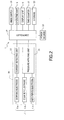
- Fig. 2 is a block diagram showing an electric configuration of the urine glucose meter 1 shown in Fig. 1 .
- the urine glucose meter 1 mainly includes a glucose sensor 11 as a measuring unit, a time counter 21 as a time counting unit, and a controller 17 as a control unit.
- the glucose sensor 11 includes at least a working electrode (first electrode) 11a and a counter electrode (second electrode) 11b as sensor electrodes, and is configured to measure a base current generated by an application of a predetermined potential in a state in which the working electrode 11a and the counter electrode 11b are in contact with (or immersed into) a preservative solution 2, and measures a peak current generated by an application of a predetermined potential in a state in which the working electrode 11a and the counter electrode 11b are in contact with (or immersed into) urine as measured sample solution.
- the time counter 21 measures an elapsed time from a contact of the working electrode 11a and the counter electrode 11b with the preservative solution 2 until the base current is measured, and a measuring time (for example, 6 seconds) from a contact of the glucose sensor 11 with the measured sample solution until a peak current for a certain period is measured.
- the controller 17 acquires a concentration of urine glucose on the basis of a base current value of the base current and a peak current value of the peak current acquired by the glucose sensor 11.
- the urine glucose meter 1 has a configuration in such a manner that when the elapsed time is equal to or longer than the stationarizing time required for the current value of the base current to return to a stationary base current value which indicates that the urine glucose (specific substance) has a reference concentration (for example, the concentration is zero), the controller 17 (control unit) acquires the concentration of the specific substance using the current value of the base current and, when the elapsed time is shorter than the stationarizing time, the controller 17 acquires the concentration of the specific substance using the stationary base current value measured by the glucose sensor 11 (measuring unit) when the elapsed time is equal to or longer than the stationarizing time instead of the current value of the base current.
- the controller 17 acquires the concentration of the specific substance using the current value of the base current and, when the elapsed time is shorter than the stationarizing time, the controller 17 acquires the concentration of the specific substance using the stationary base current value measured by the glucose sensor 11 (measuring unit) when the elapsed time is equal to
- the urine glucose meter 1 includes a urine meter body 3, a sensor holder 5, an operating unit 6, and a cap 7.
- the urine meter body 3 is a housing having the controller 17, the time counter 21 and the like integrated therein, and a display unit (LCD (Solution Crystal Display)) 9 which corresponds to a display unit (notifying unit) which displays various items of information to users at a substantially center of the urine meter body 3.
- the display 9 displays urine glucose values (urine glucose concentration), date and time of measurement, and so on.
- the operating unit 6 is used mainly for an operation for causing the display 9 to display the measurement values in the past, an operation for switching the mode to a calibration mode or a communication mode, and the like.
- the sensor holder 5 When the measurement is performed with the urine glucose meter 1, the sensor holder 5 is brought into a state of being expanded (the state shown by a solid line in Fig. 1 ). One end of the sensor holder 5 is mounted so as to be rotatable in the direction indicated by an arrow in Fig. 1 with respect to the urine meter body 3. The other end of the sensor holder 5 is provided with the glucose sensor 11, and is provided with an opening 5a so that the preservative solution 2 or urine as the measured sample solution can come into contact with the glucose sensor 11 from the outside.
- a distal end portion of the sensor holder 5 is covered with the cap 7 as indicated by an arrow 8.
- the urine glucose meter 1 is stored in a state in which the sensor holder 5 with the cap 7 fitted thereon in the expanded state is rotated toward the urine meter body 3 (the state indicated by a double-dashed chain line in Fig. 1 ) and is folded on the upper surface side of the urine meter body 3.
- the preservative solution (reference solution) 2 for returning the base current value of the glucose sensor 11 to a reference value is filled in the interior of the cap 7.
- the preservative solution 2 in the cap 7 is preferably preservative solution in which the concentration of the specific substance (urine glucose) is zero, and the state of the glucose sensor 11 is kept always in an optimal state.
- the reference solution which is capable of providing a reference concentration which can be a reference when measuring the concentration is applicable.
- Fig. 2 an electrical configuration of the urine glucose meter 1 will be described. Electrically connected to the controller 17 are the glucose sensor 11, a voltage applying unit 13, a current detecting unit 15, the controller 17, a hinge switch 19, the operating unit 6, the display 9, the time counter 21, a storage 23, and a power source 25.
- the glucose sensor 11 includes three-electrode system in which the working electrode 11a, the counter electrode 11b, and a reference electrode 11c formed of a conductive material are arranged on an insulative substrate.
- the working electrode 11a is covered with an enzyme film formed of glucose oxidase.
- the voltage applying unit 13 and the current detecting unit 15 are electrically connected to the glucose sensor 11.
- the voltage applying unit 13, the current detecting unit 15, and the glucose sensor 11, and also a lead wire that connects these members constitute a potentiostat 16 which corresponds to a measuring unit, and is configured to detect a current value of a current flowing from the working electrode 11a to the counter electrode 11b while controlling the potential of the counter electrode 11b so as to maintain the potential between the working electrode 11a and the reference electrode 11c to be constant at any time by the signal from the controller 17.
- the glucose sensor of a three-electrode system is used in this embodiment, a glucose sensor of a two-electrode system which does not have the reference electrode 11c (third electrode) may also be used.
- the storage 23 includes, for example, a RAM (Random Access Memory) or a ROM (Read Only Memory), and the like, and includes a program which operates the urine glucose meter 1, data detected by the glucose sensor 11 stored therein, and the like.
- a RAM Random Access Memory
- ROM Read Only Memory
- Switching of the urine glucose meter 1 between the measurable state and the waiting state in this embodiment is performed by the hinge switch (hinge portion) 19.
- the sensor holder 5 When the sensor holder 5 is brought into a state in which the sensor holder 5 is expanded from the urine meter body 3 (the state shown by the solid line in Fig. 1 , the first state), the device is brought into a measurable state in which a measuring process of the concentration of a specific substance contained in the measured sample solution can be performed, and when the cap 7 is mounted and the sensor holder 5 is brought into a state of being folded (the second state, the state shown by the double-dashed chain line in Fig. 1 ), the measurable state is released, and the urine glucose meter 1 is brought into the waiting state.
- the glucose sensor 11 immersed in the preservative solution 2 in the cap 7 it is preferable to configure the glucose sensor 11 immersed in the preservative solution 2 in the cap 7 to be applied with a predetermined potential.
- the state of the urine glucose meter 1 may be switched from the first state to the second state without waiting for a period from the initiation of the application of the predetermined potential until the stabilization of the base current, so that the device may be used immediately after the cap 7 has removed from the sensor holder 5, whereby the convenience for the user is improved.
- the time counter 21 as a time counting unit which counts the time is used for counting the time from when the glucose sensor 11 is immersed in the preservative solution 2 in the cap 7 until the base current of the measured sample solution is detected by the current detecting unit 15.
- the time counter 21 measures a measuring time from a contact of the glucose sensor 11 with the measured sample solution until a peak current for a certain period is measured.
- This embodiment is configured to count the elapsed time and perform the measuring process under the condition that the timing when the glucose sensor 11 is immersed in the preservative solution 2 and the timing when the hinge switch 19 is folded are performed in the same timing.
- the elapsed time from when the glucose sensor 11 is immersed in the preservative solution 2 until the sensor holder 5 is expanded and the base current value of the measured sample solution is measured with the current detecting unit 15 is acquired by counting a period from when the sensor holder 5 is folded (that is, brought into the second state) until the sensor holder 5 is expanded and the base current of the measured sample solution is measured by the current detecting unit 15.
- the urine glucose meter 1 of this embodiment has a configuration in which the measurable state and the waiting state of the urine glucose meter 1 is switched by rotating the sensor holder 5.
- a configuration to switch the same by the operation of the operating unit 6 is also possible and a configuration in which a solution crystal having a touch panel function is used for the display 9 and the switching is achieved by the operation thereof is also applicable.
- FIG. 3 is a flowchart showing a method of measurement using the urine glucose meter 1 shown in Fig. 1 ;
- Fig. 4 is a graph showing a change with time of an output current when the urine glucose value is measured with the urine glucose meter 1 shown in Fig. 1 ;
- Fig. 5 is a graph showing a change with time of an output current when the urine glucose value is measured by the urine glucose meter 1 shown in Fig. 1 (measurements for the first and the second times);
- Fig. 3 is a flowchart showing a method of measurement using the urine glucose meter 1 shown in Fig. 1
- Fig. 4 is a graph showing a change with time of an output current when the urine glucose value is measured with the urine glucose meter 1 shown in Fig. 1
- Fig. 5 is a graph showing a change with time of an output current when the urine glucose value is measured by the urine glucose meter 1 shown in Fig. 1 (measurements for the first and the second times);
- Fig. 3 is a
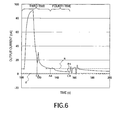
- FIG. 6 is a graph showing a change with time of the output current when the urine glucose value is measured by the urine glucose meter 1 (measurements on the third and the fourth times) shown in Fig. 1 .
- the vertical axis of the graph in Fig. 4 to Fig. 6 shows an output current value (nA) detected by the current detecting unit 15, and the lateral axis shows the time (seconds).
- the urine glucose value is measured in an elapsed time shorter than the stationarizing time.
- urine having a relatively low degree of urine glucose is measured.
- Step S1 the sensor holder 5 is expanded as indicated by the solid line in Fig. 1 , the urine glucose meter 1 is switched by the hinge switch 19 to the measurable state, and whether or not it is the initial measurement (the first measuring process) to be performed using the urine glucose meter 1 is recognized (Step S1). For example, whether or not there is a base current value or the like already acquired and stored in the storage 23 is recognized by the controller 17.
- the controller 17 determines that the measurement is the measurement for the first time (Yes, in Step S1) and the procedure goes to the next Step S2.
- the voltage applying unit 13 applies a constant potential to a point between the working electrode 11a and the counter electrode 11b, and the current value of the current flowing from the working electrode 11a to the counter electrode 11b in the waiting state is acquired by the current detecting unit 15 and stored in the storage 23 (Step S2).
- the current value acquired at this time is a stationary base current value which indicates that the urine glucose concentration in the urine under the measuring circumstances of this time is zero, for example.
- This stationary base current value is stored as data (a current value of the first base current) obtained in the measuring process (first measuring process) for the first time.
- the stationary base current value will further be described relating to the measuring process for the second time described later.
- Step S3 urine is dropped down onto the glucose sensor 11 via the opening 5a of the urine glucose meter 1 (Step S3).
- the current value of the output current flowing from the working electrode 11a to the counter electrode 11b is acquired during a predetermined period by the current detecting unit 15, and a maximum value P from among the acquired current values is stored in the storage 23 as the peak current value (Step S4).
- the peak current value is stored as data acquired in the measuring process for the first time (the current value of the first peak current).
- the controller 17 computes a urine glucose value on the basis of the difference between the stationary base current value (the current value of the first base current) acquired in Step S2, and the peak current value acquired in Step S4 (the current value of the first peak current), and causes the urine glucose value to be displayed on the display 9 (Step S5). Subsequently, the glucose sensor 11 is washed by predetermined washing solution (Step S6), is covered with the cap 7, and is immersed in the preservative solution 2 (Step S7). Furthermore, when the user rotates and folds the sensor holder 5, the urine glucose meter 1 is brought into a waiting state by the hinge switch 19.
- Step S7 the count of the elapsed time by the time counter 21 is started (Step S7), and the measuring process (the first measuring process) is terminated.
- the time counter 21 is operated by a waiting power.
- Step S1 the stationary base current value acquired in the measuring process for the first time (the first measuring process) is stored in the storage 23, it is determined that the measurement is not the first measurement (No, in Step S1), and the procedure moves to Step S8. Then, whether or not the elapsed time from when the glucose sensor 11 is immersed in the preservative solution 2 is shorter than the stationarizing time is recognized by the controller 17 on the basis of the signal from the time counter 21 (Step S8).
- a time point A is a timing when the stationary base current value is measured (Step S2 in Fig. 3 )
- a time point B is a timing when urine is dropped down (Step S3 in Fig. 3 )
- a time point C is a timing when the peak current value is reached (Step S4 in Fig. 3 ), respectively.
- a chemical electric sensor such as the glucose sensor 11 integrated in the urine glucose meter 1
- an electric bilayer is formed on an interface where electrolytic solution such as urine and electrode come into contact.
- charge is accumulated in the electrode. Therefore, a stationarizing time according to the sensor characteristics (the predetermined period from a time point E) is required until the glucose sensor 11 is washed after the measurement (a time point D in Fig. 4 , Step S6 in Fig. 3 ), and is immersed in the preservative solution 2 (the time point E in Fig. 4 , Step S7 in Fig. 3 ), until the glucose sensor 11 returns to the stationary state, that is, to a state in which the base current value showing that the urine does not contain the urine glucose is zero (stable state).
- the stationarizing time from when the glucose sensor 11 is immersed in the preservative solution 2 (the time point E, Step S7 in Fig. 3 ) until when the stable state is restored (that is, the period required until the measurement for the second time is enabled continuously) is approximately 180 seconds as shown in Fig. 4 .
- Step S7 When the elapsed time from when the glucose sensor 11 is immersed in the preservative solution 2 (Step S7) in the measuring process for the first time (the first measuring process) is recognized as being equal to or longer than the stationarizing time (No, in Step S8), the stationary base current value indicating that the urine glucose concentration is zero can be re-acquired accurately, and therefore the procedure goes to Step S2.
- Step S3 when urine is dropped down on the glucose sensor 11 by the user of the urine glucose meter 1 (Step S3), the peak current value is acquired and is stored in the storage 23 (Step S4).
- the data on the peak current value is stored as data (the current value of the second peak current) obtained in the measuring process for the second time (the second measuring process).
- the urine glucose concentration is computed by the controller 17 on the basis of the stationary base current value (current value of the second base current) and the peak current value (the current value of the second peak current) acquired in the measuring process for the second time, and is displayed on the display 9 (Step S5).
- Step S8 when the elapsed time from when the time count is started in Step S7 of the measuring process for the first time is recognized to be shorter than the stationarizing time (Yes, in Step S8), the procedure goes to Step S9.
- Such a state is shown in the measuring process for the second time in Fig. 5 for example.
- the measuring process for the second time is started after the measurement for the first time (the first measuring process) before the stationary base current value (a broken line I1 in Fig. 5 ) is returned from when the glucose sensor 11 is immersed in the preservative solution 2 (a time point E1 in Fig. 5 ).
- Step S9 a base current value in a state in which the current value of the current flowing from the working electrode 11a to the counter electrode 11b is not returned to a stationary state (I1) (for example, a time point A2 in Fig. 5 ), that is, a non-stationary base current value (I2) is obtained, and is stored in the storage 23 as a base current value for the second time (the current value of the second base current).
- a stationary state for example, a time point A2 in Fig. 5
- I2 a non-stationary base current value
- Step S10 in Fig. 3 a time point B2 in Fig. 5
- the current value of the current flowing from the working electrode 11a to the counter electrode 11b is acquired during the predetermined period by the current detecting unit 15
- a peak current value P2 as a highest value from among the acquired output current data is stored in the storage 23 as measurement data for the second time (the current value of the second peak current)
- Step S12 in Fig. 3 the current value of the second base current
- Step S5 If it is determined that the peak current value P2 acquired in the measuring process for the second time is not equal to or lower than the non-stationary base current value acquired for the second time by the controller 17 (No, in Step S12 in Fig. 3 ), the procedure goes to Step S5.
- Step S10 the non-stationary base current value 12 is acquired in the elapsed time shorter than the stationarizing time.
- computation is performed by using the stationary base current value acquired in the measurement for the first time (the current value of the first base current) I1 (Step S2 in Fig. 3 ) instead of using the non-stationary base current value I2 in the computation of the urine glucose value of this time (Step S5 in Fig. 3 ).
- the stationary base current value I1 acquired in the measuring process for the first time is used.
- latest data (latest stationary base current value) from among these data may be used.
- the measuring process for the second time (the second measuring process) is started before the stationarizing time is elapsed after the glucose sensor 11 is immersed in the preservative solution 2 (the time point El) in the measuring process for the first time (the first measuring process), and the non-stationary base current value (the current value of the second base current) I2 is acquired (the time point A2).
- the urine glucose meter 1 used in Fig. 4 is used in both of the measuring processes in Fig. 5 and in Fig. 6 described later. Therefore, as long as the environment of usage is the same, the urine glucose meter 1 indicates the same stationarizing time and the stationary base current value.
- the base current value (a broken line I2, the time point A2) measured in the measurement for the second time indicates a higher value than the stationary base current value for the first time (a broken line I1, time point A1). Therefore, when the urine glucose value is computed on the basis of the base current value for the second time, that is, the non-stationary base current value I2 and the peak current value P2 for the second time, the urine glucose value is expressed by P2-I2 (T2). However, since the original stationarizing base current value of the urine glucose meter 1 is as indicated by the I1 (broken line), the difference in current value corresponding to the urine glucose value should be P2-I1 in precisely speaking (T1). Therefore, the urine glucose value computed on the basis of the non-stationary base current value I2 obtained by the measurement for the second time has an error of ⁇ H2.
- the urine glucose measuring process is continuously performed by a plurality of times, if the measuring process is started before the stationarizing time has elapsed from when the glucose sensor 11 is immersed in the preservative solution 2, the data of the stationary base current value acquired in the measuring process performed already is used, and the urine glucose value is computed using especially the latest stationary base current value (in the case of Fig. 5 , the latest stationary base current value I1).
- the reason why the latest stationary base current value is used is for eliminating the measurement error caused by the environment of measurement by using the stationary base current value obtained at a time point temporarily close to the time point when the peak current value is measured.
- Fig. 6 shows a change with time of an output current when being measured continuously as shown in a graph in Fig. 5 , and results obtained by the measurements for the third time and the fourth time.
- the measuring process for the fourth time is started (the time point A4 in Fig. 6 ) before the stationarizing time is elapsed after the glucose sensor 11 is immersed in the preservative solution 2 (a time point E3 in Fig. 6 ) in the measuring process for the third time, and the non-stationary base current value I4 is acquired (the time point A4).
- the inventors devoted themselves to study, and found that the error might occur in the peak current value when a peak current value P4 (the time point C4) is measured before the glucose sensor 11 is returned to the stable state, especially when urine having a relatively low urine glucose concentration is measured.
- the peak current value (P2) is larger than the non-stationary base current value (I2) as shown in Fig.
- the peak current value (P2) to be measured is obtained at a sufficient accuracy. Therefore, when the peak current value P4 measured at the time point C4 in Fig. 6 is equal to or lower than the non-stationary base current value I4 measured at the time point A4, this circumstance is notified to the user of the urine glucose meter 1.
- Step S12 when the peak current value P4 is recognized to be equal to or lower than the non-stationary base current value (I4 in Fig. 6 ) (Yes, in Step S12), the fact that there is a fear that an error might be occurred in the peak current value P4 itself is notified to the user by the notifying unit of the urine glucose meter 1. More specifically, in Step S13, a notification indicating to be equal to or lower than the urine glucose value obtained by subtracting the stationary base current value I1 from the peak current value P4 acquired in the fourth measurement (for example, " ⁇ 3.9 mg/dL") is displayed on the display 9.
- character strings such as "error”, "re-measurement required” and the like which invite the user's attention may be displayed and, furthermore, the invention is not limited thereto, and means such as a buzzer or a speaker for a voice announcement may also be applicable as long as it is a notifying unit configured to invite the user's attention.
- Step S12 when the peak current value P2 is not equal to or lower than the non-stationary base current value I2 (that is, the peak current value (P2 in Fig. 5 ) is larger than the non-stationary base current value (I2 in Fig. 5 ) as in the case of the measurement for the second time shown in Fig. 5 , the procedure goes to Step S5.
- Step S5 the urine glucose value is computed and is displayed on the display 9 on the basis of the latest stationary base current value (the current value of the first base current) I1 (obtained in the measuring process for the first time in the case of the graph shown in Fig. 5 ) and the peak current value (the current value of the second peak current) P2 obtained in the measuring process for the second time.
- Step S13 or Step S5 which displays the urine glucose value
- a series of the measuring processes is terminated via the washing of the glucose sensor 11 (step S6), the immersion of the glucose sensor 11 into the preservative solution 2 , and the start of time counting (Step S7) as described above.
- the senor which employs glucose oxidase as enzyme and is configured to detect glucose is used, the invention is not limited thereto.
- a sensor which uses lactate oxidase, alcohol oxidase, cholesterol oxidase, pyruvate oxidase, amino acid oxidase, ascorbic acid oxidase or the like may be employed in order to detect the concentration of the organic substance such as lactic acid, alcohol, cholesterol, pyruvic acid, amino acid, ascorbic acid, and the like.
- the device in this embodiment is configured in such a manner that the time counting by the time counter 21 is started at a timing when the urine glucose meter 1 is switched to the waiting state by the hinge switch 19, a configuration in which a switch is provided on the sensor holder 5 and, if the cap 7 is mounted on the sensor holder 5, the time counting by the time counter 21 is started by the switch is also applicable.
- the invention is achieved as long as the glucose sensor 11 has a configuration in which the elapsed time from when the glucose sensor 11 comes into contact with the preservative solution 2 until the base current value is measured for the next time can be counted.
Landscapes
- Health & Medical Sciences (AREA)
- Chemical & Material Sciences (AREA)
- Life Sciences & Earth Sciences (AREA)
- Electrochemistry (AREA)
- Molecular Biology (AREA)
- Chemical Kinetics & Catalysis (AREA)
- Hematology (AREA)
- Physics & Mathematics (AREA)
- Analytical Chemistry (AREA)
- Biochemistry (AREA)
- General Health & Medical Sciences (AREA)
- General Physics & Mathematics (AREA)
- Immunology (AREA)
- Pathology (AREA)
- Investigating Or Analysing Biological Materials (AREA)
Abstract
The invention provides a biochemical measuring device including: a measuring unit configured to measure a base current and a peak current; a time counting unit configured to count an elapsed time from the contact of a sensor electrode to a reference solution until the start of measurement of the base current; and a control unit, wherein the control unit acquires a concentration of a specific substance using the base current value when the elapsed time is equal to or longer than a stationarizing time, and when it is shorter than the stationarizing time, acquires the concentration of the specific substance using the stationary base current value measured by the measuring unit when the elapsed time is shorter than the stationarizing time instead of the current value of the base current.
Description
- The present invention relates to a biochemical measuring device configured to measure a concentration of a specific substance contained in measured sample solution including electrolyte and, more specifically, to a biochemical measuring device configured to be capable of reducing a waiting time when measuring a concentration of a specific substance continuously.
- In the related art, a biochemical measuring device configured to measure a concentration of a specific substance contained in measured sample solution is used. As one of biochemical measuring devices,
JP-A-9-397120 - The glucose sensor is subject to chemical reaction in the measured sample solution as follows. By the action of the glucose oxidase, glucose in the measured sample solution is oxidized, oxygen is reduced to hydrogen peroxide, so that gluconolactone and hydrogen peroxide are generated. At this time, by an application of a voltage to the electrodes (the working electrode and the counter electrode), oxidizing reaction of the hydrogen peroxide is generated on the working electrode, thereby generating electrons and an oxidation current flows from the working electrode to the counter electrode, and the flowed oxidation current is measured as an oxidation current value. Since the amount of generation of the hydrogen peroxide is proportional to the amount of glucose, if the oxidation current value of the hydrogen peroxide is known, the concentration of urine glucose (glucose) can be measured.
- Therefore, when measuring the urine glucose value using the urine glucose meter, the urine glucose concentration is measured on the basis of a difference between a base current value of a base current flowed by an application of a constant potential to a point between both electrodes (the working electrode and the counter electrode) in a state of being immersed in preservative solution which does not contain the urine glucose and a peak current value of an oxidation current flowing between the both electrodes by the application of a constant potential between the both electrodes (the working electrode and the counter electrode) in the measured sample solution.
- However when a predetermined potential is applied to a point between the pair of electrodes, a charge is accumulated on a surfaces of the respective electrodes by the formation of an electric bilayer. In order to eliminate the influence of the electronic bilayer, when the urine glucose value is measured continuously by the urine glucose meter, it is required to wait for a waiting time from the termination of previous measurement and subsequent immersion of electrodes of the urine glucose meter in the preservative solution until the restoration of the base current value to a stationary current value which indicates a urine glucose concentration of zero (for example, 3 minutes) has elapsed before restarting the measurement with the urine glucose meter. Consequently, when there are a plurality of types of measured sample solution to be measured or the first measurement of the urine glucose value is failed, it is required to wait until the elapse of the waiting time before restarting the measurement.
- Accordingly, it is an object of the invention to provide a biochemical measuring device in which a waiting time from the termination of a previous measurement until becoming ready to execute the next measurement can be reduced.
- In order to solve the above-described problem, there is provided a biochemical measuring device configured to measure a concentration of a specific substance in measured sample solution containing electrolyte including: a measuring unit configured to measure a base current generated by applying a predetermined potential to a sensor electrode which is in contact with reference solution and to measure a peak current generated by applying the predetermined potential to the sensor electrode which is in contact with the measured sample solution; a time counting unit configured to count an elapsed time from the contact of the sensor electrode to the reference solution until the start of measurement of the base current; and a control unit configured to acquire a concentration of the specific substance on the basis of a current value of the base current and a current value of the peak current, wherein when the elapsed time is equal to or longer than a stationarizing time required until the current value of the base current is returned to a stationary base current value which indicates that the specific substance has a reference concentration, the control unit acquires the concentration of the specific substance using the current value of the base current, and when the elapsed time is shorter than the stationarizing time, the control unit acquires the concentration of the specific substance using the stationary base current value measured by the measuring unit when the elapsed time is equal to or longer than the stationarizing time instead of the current value of the base current.
- Preferably, when the elapsed time is shorter than the stationarizing time, the control unit acquires the concentration of the specific substance using latest data from among the stationary base current values measured by the measuring unit when the elapsed time is equal to or longer than the stationarizing time instead of the current value of the base current.
- Preferably, the base current measured by the measuring unit includes a first base current generated by an application of a predetermined potential to the sensor electrode which is in contact with the reference solution before a first measuring process and a second base current generated by an application of a predetermined potential to the sensor electrode in contact with the reference solution after the first measuring process, the peak current measured by the measuring unit includes a first peak current generated by an application of the predetermined potential to the sensor electrode which is in contact with the measured sample solution in the first measuring process and a second peak current generated by an application of the predetermined potential to the sensor electrode in contact with the measured sample solution in a second measuring process to be performed after the first measuring process, the elapsed time counted by the counting unit is an elapsed time from the contact of the sensor electrode to the reference solution after the first measuring process until the start of the measurement of the second base current, when the elapsed time is equal to or longer than a stationarizing time required until the current value of the second base current is returned to the first base current value, the control unit acquires the concentration of the specific substance of the measured sample solution in the second measuring process using the current value of the second base current and the current value of the second peak current, and when the elapsed time is shorter than the stationarizing time, the control unit acquires the concentration of the specific substance of the measured sample solution in the second measuring process using the current value of the first base current and the current value of the second peak current.
- Preferably, the biochemical measuring device of the invention further includes a notifying unit configured to remind a user when the current value of the second peak current is lower than the current value of the second base current measured by the measuring unit when the elapsed time is shorter than the stationarizing time.
- Preferably, the sensor electrode is provided at one end side of a sensor holder and the other end side of the sensor holder is coupled to a main body via a hinge portion, so that the sensor holder is configured to be rotatable between a first state in which the sensor holder is expanded from the main body and a second state in which the sensor holder is folded with respect to the main body, and the time counting unit is configured to start counting of the elapsed time by considering that the sensor electrode is brought into contact with the reference solution when the sensor holder is switched from the first state to the second state.
- Preferably, the measured sample solution is urine, and the specific substance is urine glucose.
- The invention is configured in such a manner that when the elapsed time from when the concentration of the specific substance of the previous measured sample solution is measured ends before the elapse of the stationarizing time, the acquisition is achieved when the stationarizing time is elapsed and the concentration of the specific substance is measured on the basis of the stationary base current value which indicates that the concentrate of the specific substance is zero. Therefore, the influence of the electric bilayer on the base current value to be measured may be eliminated. Consequently, according to the biochemical measuring device of the invention, accurate detection of the concentration of the specific substance is achieved even before the elapse of the stationarizing time.
-
-
Fig. 1 is a perspective view diagrammatically showing a general configuration of a urine glucose meter according to an embodiment of the invention; -
Fig. 2 is a block diagram showing an electrical configuration of the urine glucose meter shown inFig. 1 ; -
Fig. 3 is a flowchart showing a method of measurement using the urine glucose meter shown inFig. 1 ; -
Fig. 4 is a graph showing a change of an output current with time when a urine glucose value is measured with the urine glucose meter shown inFig. 1 ; -
Fig. 5 is a graph showing a change of an output current with time when the urine glucose value is measured in an elapsed time shorter than a stationarizing time with the urine glucose meter shown inFig. 1 ; and -
Fig. 6 is a graph showing a change of an output current with time when the urine glucose value of urine having a relatively low degree of urine glucose is measured with the urine glucose meter shown inFig. 1 . - Referring now to the drawings, an embodiment of a urine glucose meter to which a biochemical measuring device according to the invention is applied will be described.
Fig. 1 is a perspective view schematically showing a general configuration of aurine glucose meter 1 according to an embodiment of the invention, andFig. 2 is a block diagram showing an electric configuration of theurine glucose meter 1 shown inFig. 1 . - As shown in
Fig. 1 andFig. 2 , theurine glucose meter 1 mainly includes aglucose sensor 11 as a measuring unit, atime counter 21 as a time counting unit, and acontroller 17 as a control unit. Theglucose sensor 11 includes at least a working electrode (first electrode) 11a and a counter electrode (second electrode) 11b as sensor electrodes, and is configured to measure a base current generated by an application of a predetermined potential in a state in which the workingelectrode 11a and thecounter electrode 11b are in contact with (or immersed into) apreservative solution 2, and measures a peak current generated by an application of a predetermined potential in a state in which the workingelectrode 11a and thecounter electrode 11b are in contact with (or immersed into) urine as measured sample solution. Thetime counter 21 measures an elapsed time from a contact of the workingelectrode 11a and thecounter electrode 11b with thepreservative solution 2 until the base current is measured, and a measuring time (for example, 6 seconds) from a contact of theglucose sensor 11 with the measured sample solution until a peak current for a certain period is measured. Thecontroller 17 acquires a concentration of urine glucose on the basis of a base current value of the base current and a peak current value of the peak current acquired by theglucose sensor 11. - The
urine glucose meter 1 has a configuration in such a manner that when the elapsed time is equal to or longer than the stationarizing time required for the current value of the base current to return to a stationary base current value which indicates that the urine glucose (specific substance) has a reference concentration (for example, the concentration is zero), the controller 17 (control unit) acquires the concentration of the specific substance using the current value of the base current and, when the elapsed time is shorter than the stationarizing time, thecontroller 17 acquires the concentration of the specific substance using the stationary base current value measured by the glucose sensor 11 (measuring unit) when the elapsed time is equal to or longer than the stationarizing time instead of the current value of the base current. - In addition, respective components of the
urine glucose meter 1 will be described in detail. As shown inFig. 1 , theurine glucose meter 1 includes a urine meter body 3, asensor holder 5, anoperating unit 6, and acap 7. The urine meter body 3 is a housing having thecontroller 17, thetime counter 21 and the like integrated therein, and a display unit (LCD (Solution Crystal Display)) 9 which corresponds to a display unit (notifying unit) which displays various items of information to users at a substantially center of the urine meter body 3. Thedisplay 9 displays urine glucose values (urine glucose concentration), date and time of measurement, and so on. Theoperating unit 6 is used mainly for an operation for causing thedisplay 9 to display the measurement values in the past, an operation for switching the mode to a calibration mode or a communication mode, and the like. - When the measurement is performed with the
urine glucose meter 1, thesensor holder 5 is brought into a state of being expanded (the state shown by a solid line inFig. 1 ). One end of thesensor holder 5 is mounted so as to be rotatable in the direction indicated by an arrow inFig. 1 with respect to the urine meter body 3. The other end of thesensor holder 5 is provided with theglucose sensor 11, and is provided with an opening 5a so that thepreservative solution 2 or urine as the measured sample solution can come into contact with theglucose sensor 11 from the outside. - When storing the
urine glucose meter 1, a distal end portion of thesensor holder 5 is covered with thecap 7 as indicated by anarrow 8. Theurine glucose meter 1 is stored in a state in which thesensor holder 5 with thecap 7 fitted thereon in the expanded state is rotated toward the urine meter body 3 (the state indicated by a double-dashed chain line inFig. 1 ) and is folded on the upper surface side of the urine meter body 3. The preservative solution (reference solution) 2 for returning the base current value of theglucose sensor 11 to a reference value is filled in the interior of thecap 7. Thepreservative solution 2 in thecap 7 is preferably preservative solution in which the concentration of the specific substance (urine glucose) is zero, and the state of theglucose sensor 11 is kept always in an optimal state. However, the reference solution which is capable of providing a reference concentration which can be a reference when measuring the concentration is applicable. - Referring now to
Fig. 2 , an electrical configuration of theurine glucose meter 1 will be described. Electrically connected to thecontroller 17 are theglucose sensor 11, avoltage applying unit 13, acurrent detecting unit 15, thecontroller 17, ahinge switch 19, theoperating unit 6, thedisplay 9, thetime counter 21, astorage 23, and apower source 25. - The
glucose sensor 11 includes three-electrode system in which the workingelectrode 11a, thecounter electrode 11b, and areference electrode 11c formed of a conductive material are arranged on an insulative substrate. The workingelectrode 11a is covered with an enzyme film formed of glucose oxidase. Thevoltage applying unit 13 and thecurrent detecting unit 15 are electrically connected to theglucose sensor 11. In other words, thevoltage applying unit 13, the current detectingunit 15, and theglucose sensor 11, and also a lead wire that connects these members constitute apotentiostat 16 which corresponds to a measuring unit, and is configured to detect a current value of a current flowing from the workingelectrode 11a to thecounter electrode 11b while controlling the potential of thecounter electrode 11b so as to maintain the potential between the workingelectrode 11a and thereference electrode 11c to be constant at any time by the signal from thecontroller 17. Although the glucose sensor of a three-electrode system is used in this embodiment, a glucose sensor of a two-electrode system which does not have thereference electrode 11c (third electrode) may also be used. - The
storage 23 includes, for example, a RAM (Random Access Memory) or a ROM (Read Only Memory), and the like, and includes a program which operates theurine glucose meter 1, data detected by theglucose sensor 11 stored therein, and the like. - Switching of the
urine glucose meter 1 between the measurable state and the waiting state in this embodiment is performed by the hinge switch (hinge portion) 19. When thesensor holder 5 is brought into a state in which thesensor holder 5 is expanded from the urine meter body 3 (the state shown by the solid line inFig. 1 , the first state), the device is brought into a measurable state in which a measuring process of the concentration of a specific substance contained in the measured sample solution can be performed, and when thecap 7 is mounted and thesensor holder 5 is brought into a state of being folded (the second state, the state shown by the double-dashed chain line inFig. 1 ), the measurable state is released, and theurine glucose meter 1 is brought into the waiting state. Also in the waiting state, it is preferable to configure theglucose sensor 11 immersed in thepreservative solution 2 in thecap 7 to be applied with a predetermined potential. In this configuration, the state of theurine glucose meter 1 may be switched from the first state to the second state without waiting for a period from the initiation of the application of the predetermined potential until the stabilization of the base current, so that the device may be used immediately after thecap 7 has removed from thesensor holder 5, whereby the convenience for the user is improved. - The
time counter 21 as a time counting unit which counts the time is used for counting the time from when theglucose sensor 11 is immersed in thepreservative solution 2 in thecap 7 until the base current of the measured sample solution is detected by the current detectingunit 15. When thesensor holder 5 is folded, theurine glucose meter 1 is brought into a waiting state by thehinge switch 19, and the count of the elapsed time by thetime counter 21 is started. Also, the time counter 21 measures a measuring time from a contact of theglucose sensor 11 with the measured sample solution until a peak current for a certain period is measured. - This embodiment is configured to count the elapsed time and perform the measuring process under the condition that the timing when the
glucose sensor 11 is immersed in thepreservative solution 2 and the timing when thehinge switch 19 is folded are performed in the same timing. In other words, the elapsed time from when theglucose sensor 11 is immersed in thepreservative solution 2 until thesensor holder 5 is expanded and the base current value of the measured sample solution is measured with the current detectingunit 15 is acquired by counting a period from when thesensor holder 5 is folded (that is, brought into the second state) until thesensor holder 5 is expanded and the base current of the measured sample solution is measured by the current detectingunit 15. - The
urine glucose meter 1 of this embodiment has a configuration in which the measurable state and the waiting state of theurine glucose meter 1 is switched by rotating thesensor holder 5. However, a configuration to switch the same by the operation of theoperating unit 6 is also possible and a configuration in which a solution crystal having a touch panel function is used for thedisplay 9 and the switching is achieved by the operation thereof is also applicable. - A flow of a method of measurement of the urine glucose using the
urine glucose meter 1 will be described with reference mainly toFig. 3 to Fig. 6 .Fig. 3 is a flowchart showing a method of measurement using theurine glucose meter 1 shown inFig. 1 ;Fig. 4 is a graph showing a change with time of an output current when the urine glucose value is measured with theurine glucose meter 1 shown inFig. 1 ;Fig. 5 is a graph showing a change with time of an output current when the urine glucose value is measured by theurine glucose meter 1 shown inFig. 1 (measurements for the first and the second times);Fig. 6 is a graph showing a change with time of the output current when the urine glucose value is measured by the urine glucose meter 1 (measurements on the third and the fourth times) shown inFig. 1 . The vertical axis of the graph inFig. 4 to Fig. 6 shows an output current value (nA) detected by the current detectingunit 15, and the lateral axis shows the time (seconds). In the measuring process for the second time in the graph inFig. 5 , the urine glucose value is measured in an elapsed time shorter than the stationarizing time. In the measuring process for the fourth time in the graph inFig. 6 , urine having a relatively low degree of urine glucose is measured. - In order to start the measurement with the
urine glucose meter 1, thesensor holder 5 is expanded as indicated by the solid line inFig. 1 , theurine glucose meter 1 is switched by thehinge switch 19 to the measurable state, and whether or not it is the initial measurement (the first measuring process) to be performed using theurine glucose meter 1 is recognized (Step S1). For example, whether or not there is a base current value or the like already acquired and stored in thestorage 23 is recognized by thecontroller 17. When theurine glucose meter 1 is used for the first time this time, since there is no base current value stored in thestorage 23, it is determined that the measurement is the measurement for the first time (Yes, in Step S1) and the procedure goes to the next Step S2. - Subsequently, in a state in which the
cap 7 is mounted, that is, in a state in which theglucose sensor 11 is immersed in thepreservative solution 2, thevoltage applying unit 13 applies a constant potential to a point between the workingelectrode 11a and thecounter electrode 11b, and the current value of the current flowing from the workingelectrode 11a to thecounter electrode 11b in the waiting state is acquired by the current detectingunit 15 and stored in the storage 23 (Step S2). The current value acquired at this time is a stationary base current value which indicates that the urine glucose concentration in the urine under the measuring circumstances of this time is zero, for example. This stationary base current value is stored as data (a current value of the first base current) obtained in the measuring process (first measuring process) for the first time. The stationary base current value will further be described relating to the measuring process for the second time described later. - Subsequently, after the
cap 7 has removed from thesensor holder 5 by the user, urine is dropped down onto theglucose sensor 11 via theopening 5a of the urine glucose meter 1 (Step S3). The current value of the output current flowing from the workingelectrode 11a to thecounter electrode 11b is acquired during a predetermined period by the current detectingunit 15, and a maximum value P from among the acquired current values is stored in thestorage 23 as the peak current value (Step S4). The peak current value is stored as data acquired in the measuring process for the first time (the current value of the first peak current). - Then, the
controller 17 computes a urine glucose value on the basis of the difference between the stationary base current value (the current value of the first base current) acquired in Step S2, and the peak current value acquired in Step S4 (the current value of the first peak current), and causes the urine glucose value to be displayed on the display 9 (Step S5). Subsequently, theglucose sensor 11 is washed by predetermined washing solution (Step S6), is covered with thecap 7, and is immersed in the preservative solution 2 (Step S7). Furthermore, when the user rotates and folds thesensor holder 5, theurine glucose meter 1 is brought into a waiting state by thehinge switch 19. Simultaneously, at the timing when thesensor holder 5 is folded, the count of the elapsed time by thetime counter 21 is started (Step S7), and the measuring process (the first measuring process) is terminated. Needless to say, when theurine glucose meter 1 is kept in the waiting state, thetime counter 21 is operated by a waiting power. - Subsequently, the measuring process from the second time onward will be described. In the same manner as the measuring process for the first time, in order to start the measurement with the
urine glucose meter 1, thesensor holder 5 is expanded as indicated by the solid line inFig. 1 , theurine glucose meter 1 is switched by thehinge switch 19 to the measurable state, and whether or not the initial measurement to be performed using theurine glucose meter 1 is recognized (Step S1). At this time, since the stationary base current value acquired in the measuring process for the first time (the first measuring process) is stored in thestorage 23, it is determined that the measurement is not the first measurement (No, in Step S1), and the procedure moves to Step S8. Then, whether or not the elapsed time from when theglucose sensor 11 is immersed in thepreservative solution 2 is shorter than the stationarizing time is recognized by thecontroller 17 on the basis of the signal from the time counter 21 (Step S8). - Referring now to
Fig. 4 , the base current value and the stationarizing time will be described. InFig. 4 , a time point A is a timing when the stationary base current value is measured (Step S2 inFig. 3 ), a time point B is a timing when urine is dropped down (Step S3 inFig. 3 ), a time point C is a timing when the peak current value is reached (Step S4 inFig. 3 ), respectively. - In a chemical electric sensor such as the
glucose sensor 11 integrated in theurine glucose meter 1, an electric bilayer is formed on an interface where electrolytic solution such as urine and electrode come into contact. By the influence of the electric bilayer described above, charge is accumulated in the electrode. Therefore, a stationarizing time according to the sensor characteristics (the predetermined period from a time point E) is required until theglucose sensor 11 is washed after the measurement (a time point D inFig. 4 , Step S6 inFig. 3 ), and is immersed in the preservative solution 2 (the time point E inFig. 4 , Step S7 inFig. 3 ), until theglucose sensor 11 returns to the stationary state, that is, to a state in which the base current value showing that the urine does not contain the urine glucose is zero (stable state). - For example, when the measurement for the first time is performed on urine having a certain urine glucose concentration using the
urine glucose meter 1, the stationarizing time from when theglucose sensor 11 is immersed in the preservative solution 2 (the time point E, Step S7 inFig. 3 ) until when the stable state is restored (that is, the period required until the measurement for the second time is enabled continuously) is approximately 180 seconds as shown inFig. 4 . - When the elapsed time from when the
glucose sensor 11 is immersed in the preservative solution 2 (Step S7) in the measuring process for the first time (the first measuring process) is recognized as being equal to or longer than the stationarizing time (No, in Step S8), the stationary base current value indicating that the urine glucose concentration is zero can be re-acquired accurately, and therefore the procedure goes to Step S2. Subsequently, in the same manner as the measurement for the first time, when urine is dropped down on theglucose sensor 11 by the user of the urine glucose meter 1 (Step S3), the peak current value is acquired and is stored in the storage 23 (Step S4). The data on the peak current value is stored as data (the current value of the second peak current) obtained in the measuring process for the second time (the second measuring process). - Subsequently, the urine glucose concentration is computed by the
controller 17 on the basis of the stationary base current value (current value of the second base current) and the peak current value (the current value of the second peak current) acquired in the measuring process for the second time, and is displayed on the display 9 (Step S5). - In contrast, when the elapsed time from when the time count is started in Step S7 of the measuring process for the first time is recognized to be shorter than the stationarizing time (Yes, in Step S8), the procedure goes to Step S9. Such a state is shown in the measuring process for the second time in
Fig. 5 for example. In other words, it is a case where the measuring process for the second time (the second measuring process) is started after the measurement for the first time (the first measuring process) before the stationary base current value (a broken line I1 inFig. 5 ) is returned from when theglucose sensor 11 is immersed in the preservative solution 2 (a time point E1 inFig. 5 ). - In the measuring process for the second time shown in
Fig. 5 , in Step S9, a base current value in a state in which the current value of the current flowing from the workingelectrode 11a to thecounter electrode 11b is not returned to a stationary state (I1) (for example, a time point A2 inFig. 5 ), that is, a non-stationary base current value (I2) is obtained, and is stored in thestorage 23 as a base current value for the second time (the current value of the second base current). - Subsequently, urine is dropped down on the
glucose sensor 11 by the user (Step S10 inFig. 3 , a time point B2 inFig. 5 ), the current value of the current flowing from the workingelectrode 11a to thecounter electrode 11b is acquired during the predetermined period by the current detectingunit 15, a peak current value P2 as a highest value from among the acquired output current data is stored in thestorage 23 as measurement data for the second time (the current value of the second peak current) (Step S11 inFig. 3 , a time point C2 inFig. 5 ). Subsequently, whether or not the peak current value P2 acquired in Step S11 is equal to or lower than the non-stationary base current value acquired in Step S9 (the current value of the second base current) is recognized (Step S12 inFig. 3 ). - If it is determined that the peak current value P2 acquired in the measuring process for the second time is not equal to or lower than the non-stationary base current value acquired for the second time by the controller 17 (No, in Step S12 in
Fig. 3 ), the procedure goes to Step S5. - In the measuring process for the second time, in Step S10, the non-stationary base current value 12 is acquired in the elapsed time shorter than the stationarizing time. However, computation is performed by using the stationary base current value acquired in the measurement for the first time (the current value of the first base current) I1 (Step S2 in
Fig. 3 ) instead of using the non-stationary base current value I2 in the computation of the urine glucose value of this time (Step S5 inFig. 3 ). - Since it is the measuring process for the second time at this time, the stationary base current value I1 acquired in the measuring process for the first time is used. However, when the measuring process has already executed for the plurality of times and the stationary base current values for the plurality of times have been stored in the
storage 23, latest data (latest stationary base current value) from among these data may be used. - Here, referring now to
Fig. 5 , the reason why the non-stationary base current value is not used when computing the urine glucose value when the peak current value P2 is not equal to or lower than the non-stationary base current value acquired for the second time will be described. InFig. 5 , the measuring process for the second time (the second measuring process) is started before the stationarizing time is elapsed after theglucose sensor 11 is immersed in the preservative solution 2 (the time point El) in the measuring process for the first time (the first measuring process), and the non-stationary base current value (the current value of the second base current) I2 is acquired (the time point A2). Theurine glucose meter 1 used inFig. 4 is used in both of the measuring processes inFig. 5 and inFig. 6 described later. Therefore, as long as the environment of usage is the same, theurine glucose meter 1 indicates the same stationarizing time and the stationary base current value. - As shown in
Fig. 5 , the base current value (a broken line I2, the time point A2) measured in the measurement for the second time indicates a higher value than the stationary base current value for the first time (a broken line I1, time point A1). Therefore, when the urine glucose value is computed on the basis of the base current value for the second time, that is, the non-stationary base current value I2 and the peak current value P2 for the second time, the urine glucose value is expressed by P2-I2 (T2). However, since the original stationarizing base current value of theurine glucose meter 1 is as indicated by the I1 (broken line), the difference in current value corresponding to the urine glucose value should be P2-I1 in precisely speaking (T1). Therefore, the urine glucose value computed on the basis of the non-stationary base current value I2 obtained by the measurement for the second time has an error of ΔH2. - In order to prevent the occurrence of the error of ΔH2, in a case where the urine glucose measuring process is continuously performed by a plurality of times, if the measuring process is started before the stationarizing time has elapsed from when the
glucose sensor 11 is immersed in thepreservative solution 2, the data of the stationary base current value acquired in the measuring process performed already is used, and the urine glucose value is computed using especially the latest stationary base current value (in the case ofFig. 5 , the latest stationary base current value I1). The reason why the latest stationary base current value is used is for eliminating the measurement error caused by the environment of measurement by using the stationary base current value obtained at a time point temporarily close to the time point when the peak current value is measured. - Subsequently, referring to
Fig. 6 , the measuring process in a case where the measuring process is started at intervals shorter than the stationarizing time , and a case where the peak current value (a time point C4 inFig. 6 ) becomes equal to or lower than an acquired non-stationary base current value I4 (a time point A4 inFig. 6 ) will be described.Fig. 6 shows a change with time of an output current when being measured continuously as shown in a graph inFig. 5 , and results obtained by the measurements for the third time and the fourth time. - The measuring process for the fourth time is started (the time point A4 in
Fig. 6 ) before the stationarizing time is elapsed after theglucose sensor 11 is immersed in the preservative solution 2 (a time point E3 inFig. 6 ) in the measuring process for the third time, and the non-stationary base current value I4 is acquired (the time point A4). The inventors devoted themselves to study, and found that the error might occur in the peak current value when a peak current value P4 (the time point C4) is measured before theglucose sensor 11 is returned to the stable state, especially when urine having a relatively low urine glucose concentration is measured. In contrast, when the peak current value (P2) is larger than the non-stationary base current value (I2) as shown inFig. 5 , the peak current value (P2) to be measured is obtained at a sufficient accuracy. Therefore, when the peak current value P4 measured at the time point C4 inFig. 6 is equal to or lower than the non-stationary base current value I4 measured at the time point A4, this circumstance is notified to the user of theurine glucose meter 1. - As described above, when the peak current value P4 is recognized to be equal to or lower than the non-stationary base current value (I4 in
Fig. 6 ) (Yes, in Step S12), the fact that there is a fear that an error might be occurred in the peak current value P4 itself is notified to the user by the notifying unit of theurine glucose meter 1. More specifically, in Step S13, a notification indicating to be equal to or lower than the urine glucose value obtained by subtracting the stationary base current value I1 from the peak current value P4 acquired in the fourth measurement (for example, "≤3.9 mg/dL") is displayed on thedisplay 9. - In addition to such a display, character strings such as "error", "re-measurement required" and the like which invite the user's attention may be displayed and, furthermore, the invention is not limited thereto, and means such as a buzzer or a speaker for a voice announcement may also be applicable as long as it is a notifying unit configured to invite the user's attention.
- On the other hand, in Step S12, when the peak current value P2 is not equal to or lower than the non-stationary base current value I2 (that is, the peak current value (P2 in
Fig. 5 ) is larger than the non-stationary base current value (I2 inFig. 5 ) as in the case of the measurement for the second time shown inFig. 5 , the procedure goes to Step S5. In Step S5, the urine glucose value is computed and is displayed on thedisplay 9 on the basis of the latest stationary base current value (the current value of the first base current) I1 (obtained in the measuring process for the first time in the case of the graph shown inFig. 5 ) and the peak current value (the current value of the second peak current) P2 obtained in the measuring process for the second time. - After Step S13 or Step S5 which displays the urine glucose value, a series of the measuring processes is terminated via the washing of the glucose sensor 11 (step S6), the immersion of the
glucose sensor 11 into thepreservative solution 2 , and the start of time counting (Step S7) as described above. - In this embodiment, although the sensor which employs glucose oxidase as enzyme and is configured to detect glucose is used, the invention is not limited thereto. For example, a sensor which uses lactate oxidase, alcohol oxidase, cholesterol oxidase, pyruvate oxidase, amino acid oxidase, ascorbic acid oxidase or the like may be employed in order to detect the concentration of the organic substance such as lactic acid, alcohol, cholesterol, pyruvic acid, amino acid, ascorbic acid, and the like.
- Although the device in this embodiment is configured in such a manner that the time counting by the
time counter 21 is started at a timing when theurine glucose meter 1 is switched to the waiting state by thehinge switch 19, a configuration in which a switch is provided on thesensor holder 5 and, if thecap 7 is mounted on thesensor holder 5, the time counting by thetime counter 21 is started by the switch is also applicable. In other words, the invention is achieved as long as theglucose sensor 11 has a configuration in which the elapsed time from when theglucose sensor 11 comes into contact with thepreservative solution 2 until the base current value is measured for the next time can be counted. - The invention may be embodied in various modes without departing the essential characteristics. Therefore, needless to say, the embodiment described above is given only for description and does not limit the invention.
Claims (6)
- A biochemical measuring device configured to measure a concentration of a specific substance in measured sample solution containing electrolyte comprising:a measuring unit configured to measure a base current generated by applying a predetermined potential to a sensor electrode which is in contact with reference solution and to measure a peak current generated by applying the predetermined potential to the sensor electrode which is in contact with the measured sample solution;a time counting unit configured to count an elapsed time from the contact of the sensor electrode to the reference solution until the start of measurement of the base current; anda control unit configured to acquire a concentration of the specific substance on the basis of a current value of the base current and a current value of the peak current, whereinwhen the elapsed time is equal to or longer than a stationarizing time required until the current value of the base current is returned to a stationary base current value which indicates that the specific substance has a reference concentration, the control unit acquires the concentration of the specific substance using the current value of the base current, and
when the elapsed time is shorter than the stationarizing time, the control unit acquires the concentration of the specific substance using the stationary base current value measured by the measuring unit when the elapsed time is equal to or longer than the stationarizing time instead of the current value of the base current. - The biochemical measuring device according to Claim 1, wherein when the elapsed time is shorter than the stationarizing time, the control unit acquires the concentration of the specific substance using latest data from among the stationary base current values measured by the measuring unit when the elapsed time is equal to or longer than the stationarizing time instead of the current value of the base current.
- The biochemical measuring device according to Claim 1 or Claim 2, wherein the base current measured by the measuring unit includes a first base current generated by an application of a predetermined potential to the sensor electrode which is in contact with the reference solution before a first measuring process and a second base current generated by an application of a predetermined potential to the sensor electrode in contact with the reference solution after the first measuring process,
the peak current measured by the measuring unit includes a first peak current generated by an application of the predetermined potential to the sensor electrode which is in contact with the measured sample solution in the first measuring process and a second peak current generated by an application of the predetermined potential to the sensor electrode in contact with the measured sample solution in a second measuring process to be performed after the first measuring process,
the elapsed time counted by the counting unit is an elapsed time from the contact of the sensor electrode to the reference solution after the first measuring process until the start of the measurement of the second base current,
when the elapsed time is equal to or longer than a stationarizing time required until the current value of the second base current is returned to the first base current value, the control unit acquires the concentration of the specific substance of the measured sample solution in the second measuring process using the current value of the second base current and the current value of the second peak current, and
when the elapsed time is shorter than the stationarizing time, the control unit acquires the concentration of the specific substance of the measured sample solution in the second measuring process using the current value of the first base current and the current value of the second peak current. - The biochemical measuring device according to Claim 3, comprising a notifying unit configured to remind a user when the current value of the second peak current is lower than the current value of the second base current measured by the measuring unit when the elapsed time is shorter than the stationarizing time.
- The biochemical measuring device according to any one of Claim 1 to Claim 4, wherein the sensor electrode is provided at one end side of a sensor holder and the other end side of the sensor holder is coupled to a main body via a hinge portion, so that the sensor holder is configured to be rotatable between a first state in which the sensor holder is expanded from the main body and a second state in which the sensor holder is folded with respect to the main body, and the time counting unit is configured to start counting of the elapsed time by considering that the sensor electrode is brought into contact with the reference solution when the sensor holder is switched from the first state to the second state.
- The biochemical measuring device according to any one of Claim 1 to Claim 5, wherein the measured sample solution is urine, and the specific substance is urine glucose.
Applications Claiming Priority (1)
| Application Number | Priority Date | Filing Date | Title |
|---|---|---|---|
| JP2011109058A JP5540384B2 (en) | 2011-05-16 | 2011-05-16 | Biochemical measuring device |
Publications (1)
| Publication Number | Publication Date |
|---|---|
| EP2525217A1 true EP2525217A1 (en) | 2012-11-21 |
Family
ID=46021964
Family Applications (1)
| Application Number | Title | Priority Date | Filing Date |
|---|---|---|---|
| EP12002214A Withdrawn EP2525217A1 (en) | 2011-05-16 | 2012-03-27 | Biochemical measuring device |
Country Status (3)
| Country | Link |
|---|---|
| US (1) | US8937477B2 (en) |
| EP (1) | EP2525217A1 (en) |
| JP (1) | JP5540384B2 (en) |
Families Citing this family (3)
| Publication number | Priority date | Publication date | Assignee | Title |
|---|---|---|---|---|
| JP5713465B2 (en) * | 2012-09-14 | 2015-05-07 | 株式会社タニタ | Biosensor calibration method |
| CN112654341B (en) | 2018-10-18 | 2023-07-25 | 恩盖普有限公司 | Encapsulation |
| US11977050B2 (en) * | 2018-12-27 | 2024-05-07 | Hitachi High-Tech Corporation | Automated analyzer, automatic analysis system, and automatic sample analysis method |
Citations (4)
| Publication number | Priority date | Publication date | Assignee | Title |
|---|---|---|---|---|
| US4473458A (en) * | 1983-08-30 | 1984-09-25 | Instrument Technology Incorporated | Ion measuring device with self-contained storage of standardizing solution |
| JPH09297120A (en) | 1996-05-01 | 1997-11-18 | Omron Corp | Biochemical measuring instrument |
| US20030062262A1 (en) * | 2001-08-22 | 2003-04-03 | Sohrab Mansouri | Automated system for continuously and automatically calibrating electrochemical sensors |
| EP1936373A1 (en) * | 2006-12-20 | 2008-06-25 | Tanita Corporation | Test fluid measurement device and sensitivity calibration method thereof |
Family Cites Families (8)
| Publication number | Priority date | Publication date | Assignee | Title |
|---|---|---|---|---|
| JP2002071637A (en) * | 2000-08-25 | 2002-03-12 | Toto Ltd | Output analyzing method for electrochemical sensor and urine examination device |
| JP4721618B2 (en) * | 2000-09-25 | 2011-07-13 | 旭化成株式会社 | Enzyme electrode |
| JP2004233294A (en) * | 2003-01-31 | 2004-08-19 | Tanita Corp | Electrochemical sensor measuring device and its measuring method |
| JP2005156543A (en) * | 2003-11-05 | 2005-06-16 | Toto Ltd | Electrochemical measuring method and apparatus |
| ES2375288T3 (en) * | 2006-10-05 | 2012-02-28 | Lifescan Scotland Limited | PROCEDURE TO DETERMINE ANALYTE CONCENTRATIONS CORRECTED WITH HEMATOCRITE. |
| JP4955437B2 (en) * | 2007-03-27 | 2012-06-20 | 株式会社タニタ | Biochemical measuring instrument stand that can display the status of the biochemical measuring instrument |
| JP5114284B2 (en) * | 2008-05-02 | 2013-01-09 | 株式会社タニタ | Electrochemical sensor and portable electrochemical sensor set |
| US8025789B2 (en) * | 2008-12-17 | 2011-09-27 | General Electric Company | Anionically-charged polymer detection method |
-
2011
- 2011-05-16 JP JP2011109058A patent/JP5540384B2/en not_active Expired - Fee Related
-
2012
- 2012-03-19 US US13/424,077 patent/US8937477B2/en active Active
- 2012-03-27 EP EP12002214A patent/EP2525217A1/en not_active Withdrawn
Patent Citations (4)
| Publication number | Priority date | Publication date | Assignee | Title |
|---|---|---|---|---|
| US4473458A (en) * | 1983-08-30 | 1984-09-25 | Instrument Technology Incorporated | Ion measuring device with self-contained storage of standardizing solution |
| JPH09297120A (en) | 1996-05-01 | 1997-11-18 | Omron Corp | Biochemical measuring instrument |
| US20030062262A1 (en) * | 2001-08-22 | 2003-04-03 | Sohrab Mansouri | Automated system for continuously and automatically calibrating electrochemical sensors |
| EP1936373A1 (en) * | 2006-12-20 | 2008-06-25 | Tanita Corporation | Test fluid measurement device and sensitivity calibration method thereof |
Non-Patent Citations (1)
| Title |
|---|
| NIRTON C.S. VIEIRA ET AL: "Self-Assembled Films of Dendrimers and Metallophthalocyanines as FET-Based Glucose Biosensors", SENSORS, vol. 11, no. 10, 3 October 2011 (2011-10-03), pages 9442 - 9449, XP055032099, DOI: 10.3390/s111009442 * |
Also Published As
| Publication number | Publication date |
|---|---|
| US20120293181A1 (en) | 2012-11-22 |
| US8937477B2 (en) | 2015-01-20 |
| JP5540384B2 (en) | 2014-07-02 |
| JP2012242093A (en) | 2012-12-10 |
Similar Documents
| Publication | Publication Date | Title |
|---|---|---|
| EP1447660B1 (en) | Specific component concentration measuring method and concentration measuring instrument | |
| RU2566382C2 (en) | Control system of insufficient filling for biosensor | |
| US7491310B2 (en) | Concentration measuring method and concentration measuring apparatus | |
| CN101432620B (en) | Underfill detection system for electrochemical biosensor | |
| JP4217211B2 (en) | Sample analysis method and sample analyzer | |
| KR101289757B1 (en) | Determination of partial fill in electrochemical strips | |
| US8668819B2 (en) | Underfill recognition system for a biosensor | |
| CN1815236B (en) | Electrochemical biosensor | |
| US8937477B2 (en) | Biochemical measuring device | |
| US8975080B2 (en) | Biosensor calibration method | |
| EP2679992B1 (en) | Biological sample measuring system | |
| JP2004125668A (en) | Oxidation-reduction potential measuring instrument | |
| HK1178253B (en) | Underfill management system for a biosensor | |
| HK1206813B (en) | Method for determining analyte concentration in a sample | |
| HK1133080B (en) | Underfill detection system for an electrochemical biosensor | |
| HK1241019B (en) | System and method for detecting used and dried sensors |
Legal Events
| Date | Code | Title | Description |
|---|---|---|---|
| PUAI | Public reference made under article 153(3) epc to a published international application that has entered the european phase |
Free format text: ORIGINAL CODE: 0009012 |
|
| AK | Designated contracting states |
Kind code of ref document: A1 Designated state(s): AL AT BE BG CH CY CZ DE DK EE ES FI FR GB GR HR HU IE IS IT LI LT LU LV MC MK MT NL NO PL PT RO RS SE SI SK SM TR |
|
| AX | Request for extension of the european patent |
Extension state: BA ME |
|
| 17P | Request for examination filed |
Effective date: 20130321 |
|
| 17Q | First examination report despatched |
Effective date: 20160222 |
|
| STAA | Information on the status of an ep patent application or granted ep patent |
Free format text: STATUS: THE APPLICATION HAS BEEN WITHDRAWN |
|
| 18W | Application withdrawn |
Effective date: 20160218 |