EP2525185B1 - Pistol with firing mechanism that can easily be adapted to various modes of operation - Google Patents
Pistol with firing mechanism that can easily be adapted to various modes of operation Download PDFInfo
- Publication number
- EP2525185B1 EP2525185B1 EP10842784.0A EP10842784A EP2525185B1 EP 2525185 B1 EP2525185 B1 EP 2525185B1 EP 10842784 A EP10842784 A EP 10842784A EP 2525185 B1 EP2525185 B1 EP 2525185B1
- Authority
- EP
- European Patent Office
- Prior art keywords
- rod
- pistol
- arm
- firing device
- bolt
- Prior art date
- Legal status (The legal status is an assumption and is not a legal conclusion. Google has not performed a legal analysis and makes no representation as to the accuracy of the status listed.)
- Not-in-force
Links
Images


Classifications
-
- F—MECHANICAL ENGINEERING; LIGHTING; HEATING; WEAPONS; BLASTING
- F41—WEAPONS
- F41A—FUNCTIONAL FEATURES OR DETAILS COMMON TO BOTH SMALLARMS AND ORDNANCE, e.g. CANNONS; MOUNTINGS FOR SMALLARMS OR ORDNANCE
- F41A19/00—Firing or trigger mechanisms; Cocking mechanisms
- F41A19/06—Mechanical firing mechanisms, e.g. counterrecoil firing, recoil actuated firing mechanisms
- F41A19/13—Percussion or firing pins, i.e. fixed or slidably-mounted striker elements; Mountings therefor
-
- F—MECHANICAL ENGINEERING; LIGHTING; HEATING; WEAPONS; BLASTING
- F41—WEAPONS
- F41A—FUNCTIONAL FEATURES OR DETAILS COMMON TO BOTH SMALLARMS AND ORDNANCE, e.g. CANNONS; MOUNTINGS FOR SMALLARMS OR ORDNANCE
- F41A19/00—Firing or trigger mechanisms; Cocking mechanisms
- F41A19/06—Mechanical firing mechanisms, e.g. counterrecoil firing, recoil actuated firing mechanisms
- F41A19/16—Adjustable firing mechanisms; Trigger mechanisms with adjustable trigger pull
-
- F—MECHANICAL ENGINEERING; LIGHTING; HEATING; WEAPONS; BLASTING
- F41—WEAPONS
- F41A—FUNCTIONAL FEATURES OR DETAILS COMMON TO BOTH SMALLARMS AND ORDNANCE, e.g. CANNONS; MOUNTINGS FOR SMALLARMS OR ORDNANCE
- F41A19/00—Firing or trigger mechanisms; Cocking mechanisms
- F41A19/06—Mechanical firing mechanisms, e.g. counterrecoil firing, recoil actuated firing mechanisms
- F41A19/12—Sears; Sear mountings
-
- F—MECHANICAL ENGINEERING; LIGHTING; HEATING; WEAPONS; BLASTING
- F41—WEAPONS
- F41A—FUNCTIONAL FEATURES OR DETAILS COMMON TO BOTH SMALLARMS AND ORDNANCE, e.g. CANNONS; MOUNTINGS FOR SMALLARMS OR ORDNANCE
- F41A19/00—Firing or trigger mechanisms; Cocking mechanisms
- F41A19/06—Mechanical firing mechanisms, e.g. counterrecoil firing, recoil actuated firing mechanisms
- F41A19/15—Modular firing mechanism units
-
- F—MECHANICAL ENGINEERING; LIGHTING; HEATING; WEAPONS; BLASTING
- F41—WEAPONS
- F41A—FUNCTIONAL FEATURES OR DETAILS COMMON TO BOTH SMALLARMS AND ORDNANCE, e.g. CANNONS; MOUNTINGS FOR SMALLARMS OR ORDNANCE
- F41A19/00—Firing or trigger mechanisms; Cocking mechanisms
- F41A19/06—Mechanical firing mechanisms, e.g. counterrecoil firing, recoil actuated firing mechanisms
- F41A19/25—Mechanical firing mechanisms, e.g. counterrecoil firing, recoil actuated firing mechanisms having only slidably-mounted striker elements, i.e. percussion or firing pins
- F41A19/27—Mechanical firing mechanisms, e.g. counterrecoil firing, recoil actuated firing mechanisms having only slidably-mounted striker elements, i.e. percussion or firing pins the percussion or firing pin being movable relative to the breech-block
- F41A19/29—Mechanical firing mechanisms, e.g. counterrecoil firing, recoil actuated firing mechanisms having only slidably-mounted striker elements, i.e. percussion or firing pins the percussion or firing pin being movable relative to the breech-block propelled by a spring under tension
- F41A19/30—Mechanical firing mechanisms, e.g. counterrecoil firing, recoil actuated firing mechanisms having only slidably-mounted striker elements, i.e. percussion or firing pins the percussion or firing pin being movable relative to the breech-block propelled by a spring under tension in bolt-action guns
- F41A19/31—Sear arrangements therefor
-
- F—MECHANICAL ENGINEERING; LIGHTING; HEATING; WEAPONS; BLASTING
- F41—WEAPONS
- F41A—FUNCTIONAL FEATURES OR DETAILS COMMON TO BOTH SMALLARMS AND ORDNANCE, e.g. CANNONS; MOUNTINGS FOR SMALLARMS OR ORDNANCE
- F41A19/00—Firing or trigger mechanisms; Cocking mechanisms
- F41A19/06—Mechanical firing mechanisms, e.g. counterrecoil firing, recoil actuated firing mechanisms
- F41A19/25—Mechanical firing mechanisms, e.g. counterrecoil firing, recoil actuated firing mechanisms having only slidably-mounted striker elements, i.e. percussion or firing pins
- F41A19/27—Mechanical firing mechanisms, e.g. counterrecoil firing, recoil actuated firing mechanisms having only slidably-mounted striker elements, i.e. percussion or firing pins the percussion or firing pin being movable relative to the breech-block
- F41A19/29—Mechanical firing mechanisms, e.g. counterrecoil firing, recoil actuated firing mechanisms having only slidably-mounted striker elements, i.e. percussion or firing pins the percussion or firing pin being movable relative to the breech-block propelled by a spring under tension
- F41A19/30—Mechanical firing mechanisms, e.g. counterrecoil firing, recoil actuated firing mechanisms having only slidably-mounted striker elements, i.e. percussion or firing pins the percussion or firing pin being movable relative to the breech-block propelled by a spring under tension in bolt-action guns
- F41A19/34—Cocking mechanisms
- F41A19/35—Double-action mechanisms, i.e. the cocking being effected during the first part of the trigger pull movement
-
- F—MECHANICAL ENGINEERING; LIGHTING; HEATING; WEAPONS; BLASTING
- F41—WEAPONS
- F41A—FUNCTIONAL FEATURES OR DETAILS COMMON TO BOTH SMALLARMS AND ORDNANCE, e.g. CANNONS; MOUNTINGS FOR SMALLARMS OR ORDNANCE
- F41A19/00—Firing or trigger mechanisms; Cocking mechanisms
- F41A19/06—Mechanical firing mechanisms, e.g. counterrecoil firing, recoil actuated firing mechanisms
- F41A19/42—Mechanical firing mechanisms, e.g. counterrecoil firing, recoil actuated firing mechanisms having at least one hammer
- F41A19/43—Mechanical firing mechanisms, e.g. counterrecoil firing, recoil actuated firing mechanisms having at least one hammer in bolt-action guns
- F41A19/47—Cocking mechanisms
- F41A19/48—Double-action mechanisms, i.e. the cocking being effected during the first part of the trigger pull movement
Definitions
- the present invention refers to a pistol, more specifically a pistol comprising a firing device presenting a basic configuration which is easily adaptable for in different modes.
- a striker- fired firearm generally including a frame, a slide supported by the frame, a striker axially movable in a path of travel along a longitudinal axis, a trigger pivotably connected to the frame, a trigger bar movably coupled to the trigger and adapted to engage the striker, and a trigger bar camming member pivotably disposed in the frame and defining a camming surface engaged by the trigger bar. Pivoting the camming member moves the trigger bar from a first position to a second position in spatial relationship to the striker.
- a firing device for a pistol which, with a few modifications, may be converted so to operate in double action, single action and alternating double action/single action modes.
- another object of the present invention is to provide a family or a series of pistols comprising double action pistols, single action pistols and alternate (double or single) action pistols, produced from a basic project, so as to reduce the costs of the project, production and assembly of their components and body, thus allowing an optimization of the project and therefore of the final pistols, whichever is their mode of operation.
- a pistol directed to act in the SA mode is also disclosed, which firing device in accordance with dependent claim 3 further includes: a bushing, in the form of a cylinder with a central hole and located around the rod guiding pin and upstream of the flap of the crosswise arm of the rod, so as to limit the forward movement of said rod; and a rod ramp also comprising a disconnecting arm, which is vertically projected upwards and includes, in its upper end, a projection able to mechanically interfere with a rib, located on the inner side of the fixing wing where said bolt slides in, so as to displace said rod ramp inwardly in relation to the pistol.
- a second alternative pistol intended to work in the DA/SA mode, is provided, also comprising:
- a firing device for a pistol with only double action which device may be easily adapted to obtain a single action (SA) pistol and also a double/single action (DA/SA) pistol.
- SA single action
- DA/SA double/single action
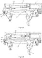
- Figure 1 is a schematic upper side view of a pistol 1 only of the double action (DAO) type, having a frame 10, including the handle 2, located on the lower back portion thereof, the lower portion of the bolt 6 and the guides (not shown) to slide said bolt 6 over the frame 10.
- the frame 10 is an injected polymeric structure provided with a few metal insertions, wherein said guides slide the bolt 6, as well as the back support 3, located above the handle 2 and intended to house part of the components of the firing device of the pistol 1, which will be disclosed in detail further below.
- the trigger guard 28 is also formed as a single part from the frame 10. Inside the handle 2, a housing is included to receive the magazine 4 intended to store and supply the cartridges 11 as known in the art.
- the trigger 5 is included, which is hinged or pivoted to said frame 10 of the pistol 1 or, more specifically, said trigger 5 is hinged to the central support of the frame 10, which is a metal part housed inside the frame 10.
- the upper portion of the pistol comprises the bolt 6 which can slide back and forth over said frame 10, by means of said four guides (not shown), said bolt 6 in its frontal portion involves the barrel 7 and the respective return spring 8.
- the chamber 9 is included in order to house a cartridge 11, which chamber is located, with the pistol 1 in a resting position, in a lengthwise position equal to the trigger 5.
- the back portion of the bolt 6 covers the firing pin 12 and the respective spring of the firing pin spring 13.
- Figures 2 to 10 showing schematic views of the firing device for the pistol 1 operated only in the double action (DAO) mode, show components of the firing device, with parts removed not to compromise the clarity of the figures.
- DAO double action
- the trigger 5, hinged to said central support of the frame 10 is hinged mounted to the rod 14, so that the movements made by the trigger 5 are transferred to the rod 14 and vice versa.
- Said rod 14 has the shape of a conformed laminar element and includes, on its end opposite to the trigger 5, a tip 16 and a crosswise arm 17. More specifically, the crosswise arm 17 is projected from the longitudinal body of the rod 14 towards the central portion of the pistol 1, and has a rear surface 18, able to mechanically interact with a finger 24 projected from the firing pin 12 and a flap 19 facing the crosswise arm 17 and projected downwards, in the central portion where an oblong hole 20 is provided, where the rod guiding pin 21 is included.
- the rod guiding pin 21 is fixed to said metal back support of the frame 10 and is intended to limit the upward and downward movement of the rod 14, but not to limit its back and forth movement.
- Said tip 16 of the rod 14 acts against the rod ramp 30 which, on a lower end, is fixed to a crosswise axle 22 and, on the opposite and upper end, has a fold projecting away from the center of the pistol 1, thus defining a contact surface with the tip 16 of the rod 14.
- the firing pin 12 is located inside the region as limited by the bolt 6 and is able to move freely, back and forth, in relation to said bolt 6. More particularly, the firing pin 12 has a cylindrical shape, provided with a tip 23 in its front portion for the percussion of the cartridge 11, and having in its rear portion a finger 24, which forms a ramp 27 on its lower back portion, intended to mechanically interact with the crosswise arm 17 of the rod 14. Furthermore, around the central portion of the firing pin 12, said firing pin spring 13 is located.
- the pistol 1 is loaded, i. e. it has a cartridge 11 in the respective chamber 9 with the magazine 4 loaded, as well as a trigger 5 in starting course, i. e. in its most advanced position. Therefore, the user starts the firing procedure by moving the trigger 5 backwards, causing the movement of the rod 14 in the same direction.
- Such movement of the rod 14 is guided by the rod guiding pin 21, so as to guarantee that said rod 14 is not displaced upwards. Consequently, and due to the mechanical interference between the rear surface 18 of the crosswise arm 17 of the rod 14 with the finger 24 of the firing pin 12, said firing pin 12 will also be moved backwards against the resistance as imposed by the firing pin spring 13, as shown by Figure 2 .
- Figure 3 is an enlarged view of the back support 3 of the pistol 1, from which we can notice that, in that point of the movement, the tip 16 of the rod 14 comes into contact with the rod ramp 30, thus forcing said rod 14 downwards and therefore lowering the crosswise arm 17 until the release of the finger 24 of the firing pin 12.
- DET 3 is an enlarged view of the back support 3 of the pistol 1, from which we can notice that, in that point of the movement, the tip 16 of the rod 14 comes into contact with the rod ramp 30, thus forcing said rod 14 downwards and therefore lowering the crosswise arm 17 until the release of the finger 24 of the firing pin 12.
- FIGS. 4 and 5 show the moment of the percussion of the cartridge 11, where we can see the rod 14 in its lowest position and the finger 24 of the firing pin in an advanced position in relation the crosswise arm 17 of the rod 14.
- cycling starts, i. e. the procedure to eliminate the fired cartridge, reload the chamber with a new cartridge and reposition the firing device for new firing.
- Said sequence of events is shown, step by step, on Figures 6 to 10 .
- the firing pin 12 follows backwards together with the bolt 6 (please see Figure 6 - maximum backwards position of the bolt).
- the bolt ends the quick clicking process, supplying the chamber 9 and returning to the front, the user starts to release the trigger 5, causing the rod 14 of the trigger to follow said forward movement (please see Figure 7 ).
- the rod 14 backwards its crosswise arm 17 hits the ramp 27 of the finger 24, thus forcing said rod 14 downwards (please Figures 8 and 9 ).
- This movement downwards is limited by the rod guide pin 21, until the crosswise arm 17 is facing the finger 24, going up and again locking the bolt 6, i. e.
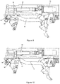
- a second embodiment of the present invention comprises a pistol 40, such as shown by Figures 11 to 20 , relative to the various steps of the firing procedure in SA mode and wherein numerical references similar to those used for Figures 2 to 10 show equal components.
- This embodiment basically shows two differences over the previously disclosed one, i. e. the presence of the bushing 42 and a disconnecting arm 43 projecting from the rod ramp 30.
- 42 shows a bushing which is located around the guide pin 21 of the rod 14 working so as to limit the range of displacement of the flap 19 of the crosswise arm 17 of the rod 14, thus preventing said rod 14 from advancing beyond a given point.
- Figures 14 and 15 are schematic upper rear views wherein the rib 45 of the bolt 6, located in the inner side of the fixing wing 46 wherein said bolt 6 slides can be identified.
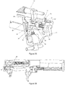
- Figure 11 is a perspective view of the back portion of the pistol 40, in an equivalent moment as shown by Figure 3 above, i. e. with the trigger 5 being pulled backward by the action of the user of the pistol 40. Also in this case, the rod 14 moves backwards and is lowered by the action of the tip 16 under the ramp 30 (please refer to Figure 12 for a similar view to Figure 11 with the rod 14 almost fully lowered). Simultaneously, the crosswise arm 17 is also lowered until the physical contact between the front surface 18 of the crosswise arm 17 and the finger 24 of the firing pin 12 is lost.
- the firing pin 12 is released and hits the cartridge 11 (please refer to Figure 13 , relative to a perspective view showing the moment of firing the gun), similarly to the disclosures on the above embodiment.
- the bolt 6 returns to its maximum backwards position, releases the fired cartridge 11 and inserts a new cartridge in the chamber 9, just as disclosed and known in the art.
- Figures 14 and 15 are schematic upper end views showing two consecutive moments during the backwards movement of the bolt 6, respectively with the rod 14 in an intermediate position ( Figure 14 ) and later in a fully upper position ( Figure 15 ).
- the tip 16 loses contact with the rod ramp 30 and is pushed upwards (we remind that, at this point, the trigger 5 is still pulled backwards by the user, thus forcing the rod 14 backwards).
- Figures 16 to 19 are upper side views showing the return of the bolt 6 from its maximum backwards position to its resting or initial position. Therefore, due to the upper position of the rod 14, the finger 24 of the firing pin 12 hits the rear surface 18 of the crosswise arm 17, and therefore cannot move forward. Said blocking effected on the rod 14 is also the result of the presence of the bushing 42 which, as stated, prevents the crosswise arm 17 of the rod 14 from moving forward (please see Figure 17 ).
- Figure 7 shows the return of the bolt 6 and the firing pin 12, which is possible due to the lowered position of the rod 14 and particularly its crosswise arm 17, allowing the finger 24 of the firing pin 12 to pass over a crosswise arm 17 with no mechanical interference between them.
- the firing pin can only return to its advanced position when the user releases the trigger 5 so it can return to its operational position in SA. More specifically, Figures 18 and 19 show intermediate return positions for the trigger 5 to its operational position in SA, with the corresponding return of the rod 14, and Figure 20 shows the pistol 40 in its final position. As we can see, the firing pin 12 gradually returns to its position just as the trigger 5 is released by the user. The finger 24 of the firing pin 12 remains in contact with the crosswise arm 17 during the whole displacement of the rod 14, remaining in this position until a new shot is fired.
- the simple and efficient inclusion of the bushing 42 and the disconnecting arm 43 allows changing both the course of displacement and the position of the crosswise arm 17, and therefore the whole rod 14. Therefore, and after the return of the bolt 6, the firing pin can no longer advance freely, since it is blocked by the crosswise arm 17, now located in a backward upper position, thus interfering with the return path of the finger 24 of the firing pin 12.
- the bushing 42 must be included in the rod guiding pin 21, to avoid the free movement forward of the rod 14 when the bolt 6 returning, and also by the inclusion disconnecting arm 43, relative to the rod ramp 30 and mechanically activated by the bolt 6.
- the pistol 50 In the present DA/SA mode of actuation, the pistol 50 must be able to work in the DA mode and in the SA mode. More specifically, said DA/SA actuation form is defined by a first shot in DA mode and by consecutive shots in SA mode, until the user returns the pistol 50 to the DA mode of firing, by voluntarily activating the external key or in the case of an involuntary firing failure.
- the inventor has devised a firing device wherein a mobile element is included, to work like the bushing 42 in the SA mode pistol 40, but which can also be displaced from its blocking position, thus allowing the pistol 50 to also work in DA mode.
- the enhancements of the present embodiment are both the disconnecting arm 43 of the rod ramp 30, with its respective upper projection 44 (just like shown and disclosed in the embodiment of the SA mode pistol 40), as well as a rod lock 51 and a respective stopper 52 for the rod lock 51.
- Figure 21 is an upper view in partial section of the back portion of the pistol 50, according to an embodiment of the present invention, in its resting position, while Figures 22 to 28 correspond to the various steps to activate the pistol 50, after starting to activate the trigger 5.
- Figure 21 initially highlights the presence of the disconnecting arm 43, which has, on its upper end, an upper projection 44, i. e. exactly the same as the disconnecting arm 43 as shown by Figures 11 to 20 for the pistol 40.
- the form of activation of the disconnecting arm 43 is exactly the same as the corresponding disconnecting arm 43 of the pistol 40, including with reference to its interaction with the bolt rib 45 present on the wing 46 of the bolt 6.
- the pistol 50 of the DA/SA mode also comprises the rod lock 51 and a respective stopper 52 (please refer specifically to Figure 23 ).
- the rod lock 51 has the shape of a hinge to a respective axle 53 located parallel to the crosswise axle of the pistol 50.
- the lower portion 54 or arm of said rod lock 51 has an external surface able to be activated by a key (not shown) fixed to the rear side of the pistol 50, said key may be activated by the user as we will see in the description of the operation of the pistol 50 further below.
- the upper portion 56 of the rod lock 51 comprises an arm 57 which extends parallel to the axle 53 of the rod lock 51, as well as a head 58 located at the upper end of said rod lock 51.
- the stopper 52 is also included, presenting basically the shape of a cube, provided with a central hole (please refer to Figure 25 ) through which said stopper 52 is assembled over the rod guiding pin 21. Furthermore, and around the rod guiding pin 21, the spring 59 is located, to push said stopper 52 forward. The stopper 52 is unable to spin around said rod guiding pin 21, since its housing in the back support 3 does not allow its angular movement. On the other hand, said stopper 52 may be displaced lengthwise, and its maximum advance position is limited by the flap 19 of the crosswise arm 17 of the rod 14.
- the stopper 52 may assume two possible positions.
- the first one is the maximum advanced position of the stopper 52, in which the arm 57 of the rod lock 51 is supported by the side of the rod lock 51, being therefore forced out against the action of the spring 55, being said position of the rod lock 51 called "open" herein.
- the second position just like better shown by Figures 24 and 25 , i. e. the maximum backward position of the stopper 52, is the position in which the stopper 52 loses contact with the arm 57 of the rod lock 51 and is kept in recess against the action of the spring 59 located around the rod guiding pin 21.
- the spring 55 acts on the lower portion 54 of the rod lock 51, causing the head 58 to be displaced to inside the pistol 50 and, more specifically, interfering with the displacement of the flap 19 of the crosswise arm 17 of the rod 14, wherein said position of the rod lock 51 is herein called "closed".
- the head 58 of the rod lock 51 takes the same position of the bushing 42 of the firing device of the pistol 40, i. e. it interferes with the advance movement of said rod 14.
- Figure 22 is a schematic view in perspective with the trigger 5 in an intermediate position, i. e. between the initial and the final firing position.
- the tip 16 abuts the rod ramp 30 during its return movement and is forced downwards due to that interaction with the rod ramp 30.
- Figures 23 and 24 are schematic perspective views in partial section showing the left side of the pistol 50, i. e. the side where the rod lock 51 is positioned, in two consecutive moments.
- Figure 25 is an upper end view with the pistol 50 in the same situation as shown by Figure 24 , i. e. shortly before firing. From those figures, we can see that, by retracting the rod 14, the stopper 52 is pushed back by the retraction movement of the flap 19 of the crosswise arm 17 of the rod 14, causing the arm 57 of the rod lock 51 to no longer abut the side surface of the stopper 52, and thus the rod lock 51 switches from the open position ( Figure 23 ) to a closed position ( Figures 24 and 25 ).
- the bolt 6 is retracted, dragging along the firing pin 12, as shown by Figure 27 , which is a schematic end perspective view. Also in this case, the retraction of the bolt 6 causes its bolt rib 45 to act on the upper projection 44 of the disconnecting arm 43, thus displacing the rod ramp 30 inwards and allowing the elevation of the crosswise arm 17 of the rod 14. Besides this known action, the finger 24 of the firing pin 12 also interacts with the head 58 of the rod lock 51,forcing said rod lock 51 to an open position, opposed to the action of the spring 55.
- Figure 28 is a similar view to Figure 27 , but with the lock in its maximum retraction position.
- said firing pin loses contact and returns to the closed position, again against the action of the spring 55 acting over the internal part of the lower portion 54 of the rod lock 51.
- this position is exactly the same as already disclosed for Figure 16 of the pistol 40, with the rod 14 with no contact with the rod ramp 30 at an upper position; furthermore, as the crosswise arm 17 is found in a closed condition, the head 58 takes the same position of the bushing 42 for the pistol 40.
- said key acting on the lower portion 54 of the rod lock 51 should be pressed. More specifically, said key is located so that, when activated, it compresses the lower portion 54, thus opening the rod lock 51. With said opening, the head 58 no longer blocks the advancement of the flap 19, and therefore the firing pin 12 and the crosswise arm 17 advance to the initial displacement position. As a consequence, the rod 14 pushes the trigger 5 to its maximum extended position, which corresponds to the initial position of use in DA mode (please refer to Figure 2 ). Therefore, the pistol 50 returns to the DA mode of action wherein, for a later shot, the trigger should be displaced throughout its path, i. e. since the maximum extended position until the firing position as fully pressed by the user.
- the scope of the invention is fully reached. From a simple and efficient device (the firing device of the pistol 1 acting in DAO mode), it is possible to reach both the pistol 40 device (SA) and the pistol 50 device (DA/SA) from the inclusion of a very limited number of parts.
- the rod ramp 30 as used additionally includes the disconnecting arm 43 and the bushing arrangement 42.
- the basic device of the pistol 1 is used, also with the substitution of the rod ramp 30 with the rod ramp 30 provided with the disconnecting arm 43 (this component is exactly the same as used in the pistol device 40), and also including the rod lock 51 and the stopper 52.
- the assembly line the conception of a basic device, which can easily form three different kinds of pistols, is something innovative and highly appreciated.
- the standardization of components in the firing device allows quicker production, with better quality and especially more economical, bearing in mind the lower quantity of different parts to be manufactured for the assembly of different guns.
- the assembly line for guns can easily support a peak in demand for a specific model of pistol, since the vast majority of their components are identical for all models liable for production from the basic device of the present invention.
Description
- The present invention refers to a pistol, more specifically a pistol comprising a firing device presenting a basic configuration which is easily adaptable for in different modes.
- The state of the art referring to fire guns, more specifically pistols, has for long incorporated various projects of firing devices, each one with its particularities. These firing devices can be divided in specific groups according to the mode of operation of the pistol, such as: single action (SA); double action (DA); or mixed (DA/SA), i. e. they can operate both in the single action mode and the double action mode, depending on the positioning of a given mechanical element of control, usually some kind of a side key on the pistol body. No matter which is the mode of operation, a common characteristic to all these pistols is the presence of a specific project and/or device for each one. However, we are unaware of a pistol or a firing device for a pistol, which optimizes its production, so as to enable the manufacture of models with different modes of operation, but with similar characteristics of operation/components.
-
WO 2009/048668 , which forms a starting point for the independent claim 1, a striker- fired firearm generally including a frame, a slide supported by the frame, a striker axially movable in a path of travel along a longitudinal axis, a trigger pivotably connected to the frame, a trigger bar movably coupled to the trigger and adapted to engage the striker, and a trigger bar camming member pivotably disposed in the frame and defining a camming surface engaged by the trigger bar. Pivoting the camming member moves the trigger bar from a first position to a second position in spatial relationship to the striker. - Therefore, it is a main object of the present invention to supply a firing device for a pistol which, with a few modifications, may be converted so to operate in double action, single action and alternating double action/single action modes.
- Furthermore, another object of the present invention is to provide a family or a series of pistols comprising double action pistols, single action pistols and alternate (double or single) action pistols, produced from a basic project, so as to reduce the costs of the project, production and assembly of their components and body, thus allowing an optimization of the project and therefore of the final pistols, whichever is their mode of operation.
- The objects above are reached and satisfied by a pistol firing device in accordance with independent claim 1.
- From the basic pistol above described , a pistol directed to act in the SA mode is also disclosed, which firing device in accordance with
dependent claim 3 further includes: a bushing, in the form of a cylinder with a central hole and located around the rod guiding pin and upstream of the flap of the crosswise arm of the rod, so as to limit the forward movement of said rod; and a rod ramp also comprising a disconnecting arm, which is vertically projected upwards and includes, in its upper end, a projection able to mechanically interfere with a rib, located on the inner side of the fixing wing where said bolt slides in, so as to displace said rod ramp inwardly in relation to the pistol. - Finally, in accordance with dependent claim 4, a second alternative pistol, intended to work in the DA/SA mode, is provided, also comprising:
- a rod ramp also comprising a disconnecting arm, which is vertically projected upwards and includes, on its upper end, a projection able to mechanically interfere with a rib, located on the inner side of the fixing wing where said bolt slides in, so as to displace said rod ramp inwardly in relation to the pistol; a rod lock in the form of a hinge over a respective axle located parallel to the longitudinal axis of the pistol, defining: a lower portion of said rod lock, having an outer surface able to be activated by a key, as well as a spring, located in the inside of said lower portion, so as to constantly push said lower portion outside, and an upper portion of the rod bolt, comprising an arm which extends parallel to the rod bolt axle, as well as a head located on the upper end of said rod bolt; and a stopper, basically in the form of a cube, provided with a central hole through which said stopper is assembled over the rod guiding pin in a position between the flap of the crosswise arm of the rod and the spring located around the rod guiding pin.
- The object of the present invention will be better understood in the light of the detailed disclosure below, presented as an illustration and not a limitation, with reference to the attached figures, wherein:
-
Figure 1 is an upper side view of a pistol of the present invention, in partial section and showing its main components; -
Figures 2 to 10 are schematic views showing a pistol with DAO mode of operation, in partial section and corresponding to the various steps of operation of this embodiment of the invention; -
Figures 11 to 20 are schematic views showing a firing device for a pistol of the present invention, only operated in the single action mode, with the switched device in relation to the basic firing device shown byFigures 2 to 10 ; and -
Figures 21 to 28 are schematic views showing a firing device for a pistol of the present invention, operated in the double action/single action mode. - According to the present invention, the objects are reached thanks to a firing device for a pistol with only double action (DAO), which device may be easily adapted to obtain a single action (SA) pistol and also a double/single action (DA/SA) pistol.
-
Figure 1 is a schematic upper side view of a pistol 1 only of the double action (DAO) type, having aframe 10, including thehandle 2, located on the lower back portion thereof, the lower portion of the bolt 6 and the guides (not shown) to slide said bolt 6 over theframe 10. In a preferable embodiment of the invention, theframe 10 is an injected polymeric structure provided with a few metal insertions, wherein said guides slide the bolt 6, as well as theback support 3, located above thehandle 2 and intended to house part of the components of the firing device of the pistol 1, which will be disclosed in detail further below. Furthermore, thetrigger guard 28 is also formed as a single part from theframe 10. Inside thehandle 2, a housing is included to receive the magazine 4 intended to store and supply thecartridges 11 as known in the art. - In an advanced position in relation to the
handle 2, thetrigger 5 is included, which is hinged or pivoted to saidframe 10 of the pistol 1 or, more specifically, saidtrigger 5 is hinged to the central support of theframe 10, which is a metal part housed inside theframe 10. The upper portion of the pistol comprises the bolt 6 which can slide back and forth over saidframe 10, by means of said four guides (not shown), said bolt 6 in its frontal portion involves the barrel 7 and the respective return spring 8. In a rearward position in relation to the barrel 7, the chamber 9 is included in order to house acartridge 11, which chamber is located, with the pistol 1 in a resting position, in a lengthwise position equal to thetrigger 5. Furthermore, the back portion of the bolt 6 covers thefiring pin 12 and the respective spring of thefiring pin spring 13. - More specifically,
Figures 2 to 10 , showing schematic views of the firing device for the pistol 1 operated only in the double action (DAO) mode, show components of the firing device, with parts removed not to compromise the clarity of the figures. - Therefore, the
trigger 5, hinged to said central support of theframe 10, is hinged mounted to therod 14, so that the movements made by thetrigger 5 are transferred to therod 14 and vice versa. Saidrod 14 has the shape of a conformed laminar element and includes, on its end opposite to thetrigger 5, atip 16 and acrosswise arm 17. More specifically, thecrosswise arm 17 is projected from the longitudinal body of therod 14 towards the central portion of the pistol 1, and has arear surface 18, able to mechanically interact with afinger 24 projected from thefiring pin 12 and aflap 19 facing thecrosswise arm 17 and projected downwards, in the central portion where anoblong hole 20 is provided, where therod guiding pin 21 is included. Therod guiding pin 21 is fixed to said metal back support of theframe 10 and is intended to limit the upward and downward movement of therod 14, but not to limit its back and forth movement. - Said
tip 16 of therod 14 acts against therod ramp 30 which, on a lower end, is fixed to acrosswise axle 22 and, on the opposite and upper end, has a fold projecting away from the center of the pistol 1, thus defining a contact surface with thetip 16 of therod 14. - As stated, the
firing pin 12 is located inside the region as limited by the bolt 6 and is able to move freely, back and forth, in relation to said bolt 6. More particularly, thefiring pin 12 has a cylindrical shape, provided with atip 23 in its front portion for the percussion of thecartridge 11, and having in its rear portion afinger 24, which forms aramp 27 on its lower back portion, intended to mechanically interact with thecrosswise arm 17 of therod 14. Furthermore, around the central portion of thefiring pin 12, said firingpin spring 13 is located. - A few other details of the above components, as well as the form of operation of the device of the present invention in the double action mode of operation, will now be particularly explained based on
Figures 2 to 10 . - On
Figure 2 (and also 10), the pistol 1 is loaded, i. e. it has acartridge 11 in the respective chamber 9 with the magazine 4 loaded, as well as atrigger 5 in starting course, i. e. in its most advanced position. Therefore, the user starts the firing procedure by moving thetrigger 5 backwards, causing the movement of therod 14 in the same direction. Such movement of therod 14 is guided by therod guiding pin 21, so as to guarantee that saidrod 14 is not displaced upwards. Consequently, and due to the mechanical interference between therear surface 18 of thecrosswise arm 17 of therod 14 with thefinger 24 of thefiring pin 12, said firingpin 12 will also be moved backwards against the resistance as imposed by thefiring pin spring 13, as shown byFigure 2 . - That same position is shown by
Figure 3 in its respective enlarged detail (DET 3), which is an enlarged view of theback support 3 of the pistol 1, from which we can notice that, in that point of the movement, thetip 16 of therod 14 comes into contact with therod ramp 30, thus forcing saidrod 14 downwards and therefore lowering thecrosswise arm 17 until the release of thefinger 24 of thefiring pin 12. - At that moment, i. e. when the
crosswise arm 17 no longer works against thefinger 24 of the firing pin, said firingpin 12 is pushed frontwards by the action of thefiring pin spring 13, causing the percussion of the ammunition located inside the chamber 9 of the barrel 7 through itstip 23. Particularly,Figures 4 and5 show the moment of the percussion of thecartridge 11, where we can see therod 14 in its lowest position and thefinger 24 of the firing pin in an advanced position in relation thecrosswise arm 17 of therod 14. - From this point, the so-called cycling starts, i. e. the procedure to eliminate the fired cartridge, reload the chamber with a new cartridge and reposition the firing device for new firing. Said sequence of events is shown, step by step, on
Figures 6 to 10 . - Therefore, after the firing and during bolt 6 cycling, caused by the gas expansion in the cartridge, the
firing pin 12 follows backwards together with the bolt 6 (please seeFigure 6 - maximum backwards position of the bolt). After the bolt ends the quick clicking process, supplying the chamber 9 and returning to the front, the user starts to release thetrigger 5, causing therod 14 of the trigger to follow said forward movement (please seeFigure 7 ). During the movement of therod 14 backwards, itscrosswise arm 17 hits theramp 27 of thefinger 24, thus forcing saidrod 14 downwards (pleaseFigures 8 and9 ). This movement downwards is limited by therod guide pin 21, until thecrosswise arm 17 is facing thefinger 24, going up and again locking the bolt 6, i. e. taking a similar position to the initial position as shown byFigures 10 and2 . Therefore, the device is fully in its initial position and, at that moment, the user may fire a new shot. We should also highlight that, as an inherent characteristic of the DA activating system for the pistol 1, thetrigger 5 returns to its initially more advanced position which, to fire a new shot, should be pulled all the back by the user, repeating the above disclosed steps. - A second embodiment of the present invention comprises a
pistol 40, such as shown byFigures 11 to 20 , relative to the various steps of the firing procedure in SA mode and wherein numerical references similar to those used forFigures 2 to 10 show equal components. This embodiment basically shows two differences over the previously disclosed one, i. e. the presence of the bushing 42 and a disconnectingarm 43 projecting from therod ramp 30. - More particularly, and with specific reference to
Figure 11 , 42 shows a bushing which is located around theguide pin 21 of therod 14 working so as to limit the range of displacement of theflap 19 of thecrosswise arm 17 of therod 14, thus preventing saidrod 14 from advancing beyond a given point. - As stated, the other change as introduced in this embodiment of the invention relates to the
rod ramp 30, which presents a disconnectingarm 43 projecting upwards and having, on its upper end, aprojection 44 able to interact with the bolt. More specifically,Figures 14 and15 are schematic upper rear views wherein therib 45 of the bolt 6, located in the inner side of thefixing wing 46 wherein said bolt 6 slides can be identified. - Therefore,
Figure 11 is a perspective view of the back portion of thepistol 40, in an equivalent moment as shown byFigure 3 above, i. e. with thetrigger 5 being pulled backward by the action of the user of thepistol 40. Also in this case, therod 14 moves backwards and is lowered by the action of thetip 16 under the ramp 30 (please refer toFigure 12 for a similar view toFigure 11 with therod 14 almost fully lowered). Simultaneously, thecrosswise arm 17 is also lowered until the physical contact between thefront surface 18 of thecrosswise arm 17 and thefinger 24 of thefiring pin 12 is lost. At that moment, thefiring pin 12 is released and hits the cartridge 11 (please refer toFigure 13 , relative to a perspective view showing the moment of firing the gun), similarly to the disclosures on the above embodiment. As a result of this shot, the bolt 6 returns to its maximum backwards position, releases the firedcartridge 11 and inserts a new cartridge in the chamber 9, just as disclosed and known in the art. - However, with the return of the bolt 6, said
bolt rib 45 acts over theupper projection 44 of the disconnectingarm 43 of therod ramp 30, causing its displacement to the center of the gun and loss of contact with thetip 16 of therod 14. More particularly,Figures 14 and15 are schematic upper end views showing two consecutive moments during the backwards movement of the bolt 6, respectively with therod 14 in an intermediate position (Figure 14 ) and later in a fully upper position (Figure 15 ). As we can see, from the displacement into therod ramp 30, thetip 16 loses contact with therod ramp 30 and is pushed upwards (we remind that, at this point, thetrigger 5 is still pulled backwards by the user, thus forcing therod 14 backwards). -
Figures 16 to 19 are upper side views showing the return of the bolt 6 from its maximum backwards position to its resting or initial position. Therefore, due to the upper position of therod 14, thefinger 24 of thefiring pin 12 hits therear surface 18 of thecrosswise arm 17, and therefore cannot move forward. Said blocking effected on therod 14 is also the result of the presence of thebushing 42 which, as stated, prevents thecrosswise arm 17 of therod 14 from moving forward (please seeFigure 17 ). Just as a comparison,Figure 7 shows the return of the bolt 6 and thefiring pin 12, which is possible due to the lowered position of therod 14 and particularly itscrosswise arm 17, allowing thefinger 24 of thefiring pin 12 to pass over acrosswise arm 17 with no mechanical interference between them. - In this case, as well as in the definition of the firing SA system, the firing pin can only return to its advanced position when the user releases the
trigger 5 so it can return to its operational position in SA. More specifically,Figures 18 and 19 show intermediate return positions for thetrigger 5 to its operational position in SA, with the corresponding return of therod 14, andFigure 20 shows thepistol 40 in its final position. As we can see, thefiring pin 12 gradually returns to its position just as thetrigger 5 is released by the user. Thefinger 24 of thefiring pin 12 remains in contact with thecrosswise arm 17 during the whole displacement of therod 14, remaining in this position until a new shot is fired. We should highlight that, in the operational position as shown byFigure 20 , thetrigger 5 and therod 14 remain in an intermediate position between the initial position of the pistol 40 (Figure 11 ) and the firing position of the gun. Said effect is due to the presence of thebushing 42 limiting the return path of therod 14 and therefore thetrigger 5. In the following shot, the user will need to move thetrigger 5 through a shorter path to release thefiring pin 12 and fire thecartridge 11, i. e. eliminating the whole initial step of movement backwards of the rod to engage thefinger 24 of thefiring pin 12, just like in the DA operation mode. - We should also highlight that, during the return of the firing pin to its initial advanced position, the bolt has already returned to its respective advanced position and, therefore, the
bolt rib 45 of thewing 46 no longer acts on theupper projection 44 of the disconnectingarm 43 of therod ramp 30, and therefore thetip 16 of therod 14 is again in contact with saidrod ramp 30. - As previously stated, the differences existing between the SA embodiment (
Figures 11 to 20 ) and the DAO embodiment are limited to the inclusion of thebushing 42 and the disconnectingarm 43. Thebolt rib 45 is also present in the DAO embodiment, but saidbolt rib 45 does not act on therod ramp 30 due to the non-existence of said disconnectingarm 43 and therespective projection 44. Said solution allows to reach the objects of maximum standardization of the production line, whichever is the model of pistol to be produced, i. e. reducing at maximum the differences and particularities between them. - Anyway, the simple and efficient inclusion of the
bushing 42 and the disconnectingarm 43 allows changing both the course of displacement and the position of thecrosswise arm 17, and therefore thewhole rod 14. Therefore, and after the return of the bolt 6, the firing pin can no longer advance freely, since it is blocked by thecrosswise arm 17, now located in a backward upper position, thus interfering with the return path of thefinger 24 of thefiring pin 12. - We will now disclose the last embodiment of the present invention, as specifically shown by
Figures 21 to 28 , wherein numeric references similar to those used forFigures 1 to 20 show equivalent components. Particularly, the firing device of this embodiment of the pistol allows its use in both DA and SA modes, depending on the circumstances. - As preliminarily seen, in order for the basic device of the SA pistol at issue, acting in DAO mode, to be built so as to be altered to work in SA mode, the
bushing 42 must be included in therod guiding pin 21, to avoid the free movement forward of therod 14 when the bolt 6 returning, and also by theinclusion disconnecting arm 43, relative to therod ramp 30 and mechanically activated by the bolt 6. - In the present DA/SA mode of actuation, the
pistol 50 must be able to work in the DA mode and in the SA mode. More specifically, said DA/SA actuation form is defined by a first shot in DA mode and by consecutive shots in SA mode, until the user returns thepistol 50 to the DA mode of firing, by voluntarily activating the external key or in the case of an involuntary firing failure. For that purpose, the inventor has devised a firing device wherein a mobile element is included, to work like thebushing 42 in theSA mode pistol 40, but which can also be displaced from its blocking position, thus allowing thepistol 50 to also work in DA mode. - Therefore, and in comparison with the firing device of the DA mode pistol 1, the enhancements of the present embodiment are both the disconnecting
arm 43 of therod ramp 30, with its respective upper projection 44 (just like shown and disclosed in the embodiment of the SA mode pistol 40), as well as arod lock 51 and arespective stopper 52 for therod lock 51. - Therefore,
Figure 21 is an upper view in partial section of the back portion of thepistol 50, according to an embodiment of the present invention, in its resting position, whileFigures 22 to 28 correspond to the various steps to activate thepistol 50, after starting to activate thetrigger 5. - Specifically,
Figure 21 initially highlights the presence of the disconnectingarm 43, which has, on its upper end, anupper projection 44, i. e. exactly the same as the disconnectingarm 43 as shown byFigures 11 to 20 for thepistol 40. We should also highlight that the form of activation of the disconnectingarm 43 is exactly the same as the corresponding disconnectingarm 43 of thepistol 40, including with reference to its interaction with thebolt rib 45 present on thewing 46 of the bolt 6. - Furthermore, and as a specific innovation for this embodiment of the invention, the
pistol 50 of the DA/SA mode also comprises therod lock 51 and a respective stopper 52 (please refer specifically toFigure 23 ). Particularly, therod lock 51 has the shape of a hinge to arespective axle 53 located parallel to the crosswise axle of thepistol 50. Thelower portion 54 or arm of saidrod lock 51 has an external surface able to be activated by a key (not shown) fixed to the rear side of thepistol 50, said key may be activated by the user as we will see in the description of the operation of thepistol 50 further below. Furthermore, saidlower portion 54 of therod lock 51 is constantly pushed out by the action of thespring 55, for which reason theupper portion 56 or arm of therod lock 51 is correspondingly pushed inside, always in relation to the body of thepistol 50. Theupper portion 56 of therod lock 51 comprises anarm 57 which extends parallel to theaxle 53 of therod lock 51, as well as ahead 58 located at the upper end of saidrod lock 51. - The
stopper 52 is also included, presenting basically the shape of a cube, provided with a central hole (please refer toFigure 25 ) through which saidstopper 52 is assembled over therod guiding pin 21. Furthermore, and around therod guiding pin 21, thespring 59 is located, to push saidstopper 52 forward. Thestopper 52 is unable to spin around saidrod guiding pin 21, since its housing in theback support 3 does not allow its angular movement. On the other hand, saidstopper 52 may be displaced lengthwise, and its maximum advance position is limited by theflap 19 of thecrosswise arm 17 of therod 14. - Concerning the
rod lock 51 and, more specifically, thearm 57 of saidrod lock 51, thestopper 52 may assume two possible positions. The first one, as shown byFigure 23 , is the maximum advanced position of thestopper 52, in which thearm 57 of therod lock 51 is supported by the side of therod lock 51, being therefore forced out against the action of thespring 55, being said position of therod lock 51 called "open" herein. The second position, just like better shown byFigures 24 and 25 , i. e. the maximum backward position of thestopper 52, is the position in which thestopper 52 loses contact with thearm 57 of therod lock 51 and is kept in recess against the action of thespring 59 located around therod guiding pin 21. In that position, and since thearm 57 of therod lock 51 loses contact with thestopper 52, thespring 55 acts on thelower portion 54 of therod lock 51, causing thehead 58 to be displaced to inside thepistol 50 and, more specifically, interfering with the displacement of theflap 19 of thecrosswise arm 17 of therod 14, wherein said position of therod lock 51 is herein called "closed". Particularly, we should highlight that, in a closed position, thehead 58 of therod lock 51 takes the same position of thebushing 42 of the firing device of thepistol 40, i. e. it interferes with the advance movement of saidrod 14. - The inter-relationship between these components and the other components as common to all embodiments of the
pistols pistol 50 is fired. - Therefore, we start from the initial position as shown by
Figure 21 , wherein thepistol 50 is ready to fire, with thetrigger 5 in its extended resting position and therod 14 also in its maximum extended position and interacting with thefinger 24 of thefiring pin 12. - Just like in the previous embodiments,
Figure 22 is a schematic view in perspective with thetrigger 5 in an intermediate position, i. e. between the initial and the final firing position. In that moment, thetip 16 abuts therod ramp 30 during its return movement and is forced downwards due to that interaction with therod ramp 30. -
Figures 23 and24 are schematic perspective views in partial section showing the left side of thepistol 50, i. e. the side where therod lock 51 is positioned, in two consecutive moments.Figure 25 is an upper end view with thepistol 50 in the same situation as shown byFigure 24 , i. e. shortly before firing. From those figures, we can see that, by retracting therod 14, thestopper 52 is pushed back by the retraction movement of theflap 19 of thecrosswise arm 17 of therod 14, causing thearm 57 of therod lock 51 to no longer abut the side surface of thestopper 52, and thus therod lock 51 switches from the open position (Figure 23 ) to a closed position (Figures 24 and 25 ). - When the
trigger 5 reaches the end of its path, exactly as previously disclosed, thefinger 24 of thefiring pin 12 loses contact with therear surface 18 of thecrosswise arm 17, and is then quickly advanced by the action of thefiring pin spring 13, striking and firing thecartridge 11 located inside the chamber 9 (please refer toFigure 26 ). - After the shot, as disclosed for the
pistol 40, the bolt 6 is retracted, dragging along thefiring pin 12, as shown byFigure 27 , which is a schematic end perspective view. Also in this case, the retraction of the bolt 6 causes itsbolt rib 45 to act on theupper projection 44 of the disconnectingarm 43, thus displacing therod ramp 30 inwards and allowing the elevation of thecrosswise arm 17 of therod 14. Besides this known action, thefinger 24 of thefiring pin 12 also interacts with thehead 58 of therod lock 51,forcing saidrod lock 51 to an open position, opposed to the action of thespring 55. It is important to highlight that, due to the configuration of thehead 58 of therod lock 51, it does not impede the retraction movement of thefiring pin 12, since its sides have the shape of a ramp, allowing the displacement of saidhead 58 towards to the outside (open position of the rod lock 51). -
Figure 28 is a similar view toFigure 27 , but with the lock in its maximum retraction position. After thefinger 24 of thefiring pin 12 passes through its region of interaction with thehead 58, said firing pin loses contact and returns to the closed position, again against the action of thespring 55 acting over the internal part of thelower portion 54 of therod lock 51. Mechanically, this position is exactly the same as already disclosed forFigure 16 of thepistol 40, with therod 14 with no contact with therod ramp 30 at an upper position; furthermore, as thecrosswise arm 17 is found in a closed condition, thehead 58 takes the same position of thebushing 42 for thepistol 40. - From this point on, the return movement of the trigger, made step by step and progressively released by the user, is exactly the same as already disclosed for the
pistol 40. Therefore, with the return of thetrigger 5 and the bolt 6, thefiring pin 12 moves only partially forward, since its advance movement is blocked by therear surface 18 of the rod 14 (in an upper position). Since therod lock 51 is in closed position, therod 14 does not move fully forwards, the device is forced to work in the SA mode and the path of the trigger is reduced (this effect is exactly the same as found when the trigger returns to the device of the pistol 40). The effect of trigger return may be shown fromFigures 17 to 20 , keeping in mind that the blocking action then made by thebushing 42 is now undertaken by thehead 58 of therod lock 51 in its closed position. - To return the
pistol 50 to the DA mode of action, said key (not shown) acting on thelower portion 54 of therod lock 51 should be pressed. More specifically, said key is located so that, when activated, it compresses thelower portion 54, thus opening therod lock 51. With said opening, thehead 58 no longer blocks the advancement of theflap 19, and therefore thefiring pin 12 and thecrosswise arm 17 advance to the initial displacement position. As a consequence, therod 14 pushes thetrigger 5 to its maximum extended position, which corresponds to the initial position of use in DA mode (please refer toFigure 2 ). Therefore, thepistol 50 returns to the DA mode of action wherein, for a later shot, the trigger should be displaced throughout its path, i. e. since the maximum extended position until the firing position as fully pressed by the user. - Finally, if there is a percussion failure, i. e. the
cartridge 11 is not fired, the backward displacement of the bolt will not occur and, for this reason, thefinger 24 of thefiring pin 12 will not allow therod lock 51 to close, leaving the device in DA mode of action. As soon as the user releases the trigger and then pull it back again, therod 14 will be able to abut thefinger 24 of thefiring pin 12, retracting thefiring pin 12 and putting thepistol 50 in pre-shot position. Said action is possible, since therod lock 51 is in open position and therod 14 is in the same position as shown byFigure 21 . - From the above detailed description, we can conclude that the scope of the invention is fully reached. From a simple and efficient device (the firing device of the pistol 1 acting in DAO mode), it is possible to reach both the
pistol 40 device (SA) and thepistol 50 device (DA/SA) from the inclusion of a very limited number of parts. Especially, to enable the construction of thepistol 40 from the basic device of the pistol 1, therod ramp 30 as used additionally includes the disconnectingarm 43 and thebushing arrangement 42. In the same fashion, to build thepistol 50, the basic device of the pistol 1 is used, also with the substitution of therod ramp 30 with therod ramp 30 provided with the disconnecting arm 43 (this component is exactly the same as used in the pistol device 40), and also including therod lock 51 and thestopper 52. - We can also notice that the bolt 6 as used in any of the disclosed embodiments is not changed in any way, particularly regarding the inclusion of the
bolt rib 45 internally located in thewing 46. This is possible, since, in the DAO action model (pistol 1,Figures 1 to 10 ), saidbolt rib 45 does not interfere with therod ramp 30, due to the absence of the disconnectingarm 43. - Regarding the assembly line, the conception of a basic device, which can easily form three different kinds of pistols, is something innovative and highly appreciated. The standardization of components in the firing device allows quicker production, with better quality and especially more economical, bearing in mind the lower quantity of different parts to be manufactured for the assembly of different guns. Furthermore, the assembly line for guns can easily support a peak in demand for a specific model of pistol, since the vast majority of their components are identical for all models liable for production from the basic device of the present invention.
Claims (4)
- Pistol firing device easily adaptable to different modes of operation, comprising- a frame (10) on top of which a bolt (6) slides, said frame comprising- a handle (2), which houses a magazine (4),- a trigger guard (28) involving a trigger (5) and- a metal back support (3) for housing some of the components of the pistol firing device (1, 40 , 50),
wherein- said trigger (5) is pivotly mounted to a first end of a rod (14), wherein an end (16) of said rod (14) opposite to the first end is located on the back support (3), - said bolt (6) involves and houses a firing pin (12) located on a rear side of said bolt (6) and aligned with a chamber (9) wherein a cartridge (11) is located,- said firing pin (12) has- around its front portion a firing pin spring (13), which acts on a stop
and- on the rear portion of the firing pin (12) a finger (24) which projects downwards,- said rod (14) having the shape of a laminar element and including on said opposed end to the trigger (5) a tip (16) and a crosswise arm (17), wherein said crosswise arm (17)- is projected from a longitudinal body of the rod (14), towards a central portion of the pistol firing device (1, 40, 50)- has a rear surface (18), able to mechanically interact with said finger (24) of the firing pin (12), and- has a flap (19) on the front surface of the crosswise arm (17), facing the crosswise arm (17) and projecting downwards,- said flap (19) comprising in a central portion of said flap (19) an oblong hole (20);said pistol firing device further comprising:- a rod guiding pin (21), fixed to the back support (3) and with a guiding pin axle parallel to the length of the pistol firing device (1, 40, 50), wherein said rod guiding pin (21) traverses the oblong hole (20) of the flap (19) of the crosswise arm (17), so as to limit the upwards and downward movement of said crosswise arm (17);
and- a rod ramp (30) in the form of an elongated laminar body,- fixed at a lower end to a crosswise axle (22)
and- on an opposite upper end having a fold projecting away from the center of the pistol firing device (1, 40, 50), thus defining a contact surface that mechanically works against the tip (16) of the rod (14). - Pistol firing device of claim 1, characterized by said pistol firing device (40) is directed to work in the DAO mode.
- Pistol firing device of claim 1, characterized by said pistol firing device (40) is directed to work in the SA mode, and further comprises:- a bushing (42), shaped as a cylinder with a central hole, and located around the rod guiding pin (21) and upstream from the flap (19) of the crosswise arm (17) of the rod (14), so to limit the forward movement of said rod (14); and- a rod ramp (30') also comprising a disconnecting arm (43), which is vertically projected upwards and includes, on its upper end, a projection (44) able to mechanically interfere with a bolt rib (45), located in the inner side of a wing (46) wherein said bolt (6) slides to displace said rod ramp (30) inwardly in relation to the pistol firing device (40).
- Pistol firing device of claim 1, characterized by said pistol firing device (50) is directed to work in the DA/SA mode, and further comprises:- a rod ramp (30') also comprising a disconnecting arm (43), which is vertically projected upwards and includes, on its upper end, a projection (44) able to mechanically interfere with a bolt rib (45), located in the inner side of a wing (46) wherein said bolt (6) slides to displace said rod ramp (30') inwardly in relation to the pistol firing device (50);- a rod lock (51) with the shape of a hinge to a respective axle (53) located in parallel to the longitudinal axis of the pistol firing device (50) and defining:- a lower portion (54) of said rod lock (51), having an outer surface able to be acted on by a key as well as a spring (55), located inside said lower portion (54) in order to constantly push said lower portion (54) out; and- an upper portion (56) of the rod lock (51), comprising an arm (57) extending parallel to the axle (53) of the rod lock (51), as well as a head (58) located on the upper end of said lock rod (51); and- a stopper (52), basically in the form of a cube, provided with a central hole (60) through which said stopper (52) is assembled over the rod guiding pin (21) in a position between the flap (19) of the crosswise arm (17) of the rod (14) and the spring (59) located around the rod guiding pin (21).
Applications Claiming Priority (1)
| Application Number | Priority Date | Filing Date | Title |
|---|---|---|---|
| PCT/BR2010/000015 WO2011085458A1 (en) | 2010-01-15 | 2010-01-15 | Pistol with firing mechanism that can easily be adapted to various modes of operation |
Publications (3)
| Publication Number | Publication Date |
|---|---|
| EP2525185A1 EP2525185A1 (en) | 2012-11-21 |
| EP2525185A4 EP2525185A4 (en) | 2015-04-22 |
| EP2525185B1 true EP2525185B1 (en) | 2018-01-03 |
Family
ID=44303742
Family Applications (1)
| Application Number | Title | Priority Date | Filing Date |
|---|---|---|---|
| EP10842784.0A Not-in-force EP2525185B1 (en) | 2010-01-15 | 2010-01-15 | Pistol with firing mechanism that can easily be adapted to various modes of operation |
Country Status (3)
| Country | Link |
|---|---|
| US (1) | US8925232B2 (en) |
| EP (1) | EP2525185B1 (en) |
| WO (1) | WO2011085458A1 (en) |
Families Citing this family (18)
| Publication number | Priority date | Publication date | Assignee | Title |
|---|---|---|---|---|
| ITBS20130170A1 (en) * | 2013-11-18 | 2015-05-19 | Francesco Ghitti | FIRE WEAPON DRIVE WITH THUMB |
| ES2606327T3 (en) * | 2013-12-11 | 2017-03-23 | Glock Technology Gmbh | Spring for the trigger pusher of a gun |
| SK288474B6 (en) * | 2014-09-18 | 2017-08-02 | Grand Power, S.R.O. | Trigger mechanism for auto-loading weapon, and auto-loading manual weapon |
| SK288609B6 (en) * | 2015-05-25 | 2018-11-05 | Grand Power, S.R.O. | Trigger mechanism of semi-automatic weapon without a hammer with direct striker and semi-automatic weapon |
| CZ306586B6 (en) | 2015-11-11 | 2017-03-15 | Česká Zbrojovka A.S. | A trigger mechanism for automatic and semiautomatic guns |
| US10739095B2 (en) * | 2015-12-01 | 2020-08-11 | Mean L.L.C. | Firearm operating system |
| USD779620S1 (en) * | 2015-12-28 | 2017-02-21 | George Huang | Enhanced magazine release |
| JP6129397B1 (en) * | 2016-12-16 | 2017-05-17 | 正 常定 | rifle |
| US10684087B2 (en) * | 2017-10-10 | 2020-06-16 | Sig Sauer, Inc. | Handgun sear with multiple engagement surfaces |
| US10760861B2 (en) * | 2018-01-22 | 2020-09-01 | Springfield, Inc. | Firearm slide with sloped bottom surface |
| WO2019172054A1 (en) * | 2018-03-08 | 2019-09-12 | Jsr株式会社 | Radiation sensitive resin composition, method for producing same and resist pattern forming method |
| US11280570B2 (en) | 2019-03-11 | 2022-03-22 | James Matthew Underwood | Firearm operating mechanisms and bolt release |
| US11371789B2 (en) | 2019-08-06 | 2022-06-28 | James Matthew Underwood | Roller delayed firearm operating system |
| EP3901555A1 (en) * | 2020-04-23 | 2021-10-27 | FN Herstal SA | Firing pin safety mechanism for a gun |
| US11543195B2 (en) | 2020-07-03 | 2023-01-03 | James Matthew Underwood | Roller and bearing delayed firearm operating systems |
| WO2023022723A1 (en) * | 2021-08-19 | 2023-02-23 | Tactical Industry Innovations, Llc | Trigger system |
| HRP20231474T1 (en) | 2021-06-01 | 2024-03-01 | Glock Technology Gmbh | Trigger device for a handgun |
| US11846476B2 (en) | 2021-10-07 | 2023-12-19 | James Matthew Underwood | Ejector for firearm |
Family Cites Families (23)
| Publication number | Priority date | Publication date | Assignee | Title |
|---|---|---|---|---|
| US3722358A (en) | 1971-01-14 | 1973-03-27 | L Seecamp | Combined single and double action firing mechanisms for pistols and kits for converting single-action pistols |
| AT368807B (en) * | 1981-04-30 | 1982-11-10 | Glock Gaston | PISTOL |
| US5160796A (en) * | 1991-10-07 | 1992-11-03 | Martin Tuma | Automatic small arm |
| US5386659A (en) * | 1993-12-17 | 1995-02-07 | Smith & Wesson Corp. | Fire control mechanism for semiautomatic pistols |
| DE19507052A1 (en) | 1995-03-01 | 1996-09-05 | Walther Carl Gmbh | Firearm trigger |
| US5640794A (en) * | 1995-07-07 | 1997-06-24 | Fn Manufacturing, Inc. | Fire control mechanism for an automatic pistol |
| US5797206A (en) * | 1996-12-26 | 1998-08-25 | Smith & Wesson Corp. | Method for reversibly converting a traditional double action pistol to a single action, target pistol |
| BR9700178A (en) * | 1997-01-31 | 1998-12-01 | Forjas Taurus Sa | Firing mechanism for firearms |
| US6308448B1 (en) * | 1999-04-30 | 2001-10-30 | Smith & Wesson Corporation | Angled interlocked firing mechanism |
| US6354032B1 (en) * | 2000-10-06 | 2002-03-12 | Arthur Viani | Trigger stop |
| US6865979B1 (en) * | 2001-02-07 | 2005-03-15 | Smith & Wesson Corp. | Apparatus and method for removing the slide of a semi-automatic pistol |
| US6560909B2 (en) * | 2001-06-22 | 2003-05-13 | Joseph Cominolli | Manual safety for linear striker fired semi-automatic or automatic pistols |
| US7194833B1 (en) * | 2003-02-10 | 2007-03-27 | Smith & Wesson Corp. | Firing mechanism for semi-automatic pistols |
| BR0301483B1 (en) | 2003-05-23 | 2014-01-07 | SAFETY DEVICE ON THE SHOOTING MECHANISM FOR SEMI-AUTOMATIC DOUBLE-ACTION DOUBLE GUNS | |
| US20050034344A1 (en) * | 2003-08-14 | 2005-02-17 | Arthur Viani | Self cleaning trigger control connector & connector |
| AT413444B (en) * | 2004-06-09 | 2006-02-15 | Gen Headquarters Of The Armed | PISTOL WITH EXTRACTION DEVICE |
| US7392611B2 (en) * | 2004-12-22 | 2008-07-01 | Smith & Wesson Corp. | Apparatus and method for firearm takedown |
| US7617628B2 (en) * | 2004-12-22 | 2009-11-17 | Smith & Wesson Corp. | Fire control mechanism for a firearm |
| US20060236581A1 (en) * | 2005-04-25 | 2006-10-26 | Arthur Viani | Self-cleaning trigger connector system |
| ATE436002T1 (en) * | 2006-07-11 | 2009-07-15 | Sat Swiss Arms Technology Ag | TRIGGER DEVICE FOR HAND GUNS |
| US7810268B1 (en) * | 2007-07-25 | 2010-10-12 | Sturm Ruger & Company, Inc. | Striker-fired firearm |
| BG66145B1 (en) * | 2007-11-23 | 2011-07-29 | ПЕЕВ Владимир | Double-action trigger with short meshing |
| US8572878B2 (en) * | 2010-05-28 | 2013-11-05 | Beretta Usa Corp. | De-cocking mechanism for striker-fired semi-automatic pistols |
-
2010
- 2010-01-15 US US13/582,256 patent/US8925232B2/en active Active
- 2010-01-15 WO PCT/BR2010/000015 patent/WO2011085458A1/en active Application Filing
- 2010-01-15 EP EP10842784.0A patent/EP2525185B1/en not_active Not-in-force
Non-Patent Citations (1)
| Title |
|---|
| None * |
Also Published As
| Publication number | Publication date |
|---|---|
| EP2525185A4 (en) | 2015-04-22 |
| EP2525185A1 (en) | 2012-11-21 |
| US8925232B2 (en) | 2015-01-06 |
| US20130000171A1 (en) | 2013-01-03 |
| WO2011085458A1 (en) | 2011-07-21 |
Similar Documents
| Publication | Publication Date | Title |
|---|---|---|
| EP2525185B1 (en) | Pistol with firing mechanism that can easily be adapted to various modes of operation | |
| EP3129739B1 (en) | Fire control system for firearms | |
| JP5932445B2 (en) | Airgun bullet firing mechanism | |
| EP3296682B1 (en) | Shock-absorption device for gun bolt stop | |
| HUT64141A (en) | Semi-automatic firearm with increased safety pin | |
| KR100304180B1 (en) | Toy gun with automatic bullet supply mechanism | |
| TWI570383B (en) | Toy gun | |
| US4015512A (en) | Gas-operated firearm | |
| WO2015080775A1 (en) | Firing blocker mechanism for firearm | |
| US11578939B2 (en) | Safety mechanism for firearms | |
| CA2653036C (en) | Locking mechanism of a hand firearm | |
| EP3407002B1 (en) | Break barrel rifle with pellet loading system | |
| JPH0348439B2 (en) | ||
| US2372327A (en) | Eiring-control mechanism | |
| JP5567537B2 (en) | Device for changing the number of bullets in a bullet feed mechanism | |
| JP6758721B2 (en) | Cocking indicator device in simulated gun | |
| EP3276293B1 (en) | Bullet feed port opening and closing device in imitation gun | |
| ITVR20110219A1 (en) | COMPRESSED AIR WEAPON | |
| CZ306969B6 (en) | A sealed single-action revolver | |
| JP2003194496A (en) | Toy air-gun | |
| MXPA06007961A (en) | Tripping mechanism. | |
| KR20040087261A (en) | A toy gun's shooting device | |
| GB1590096A (en) | Gun |
Legal Events
| Date | Code | Title | Description |
|---|---|---|---|
| PUAI | Public reference made under article 153(3) epc to a published international application that has entered the european phase |
Free format text: ORIGINAL CODE: 0009012 |
|
| 17P | Request for examination filed |
Effective date: 20120816 |
|
| AK | Designated contracting states |
Kind code of ref document: A1 Designated state(s): AT BE BG CH CY CZ DE DK EE ES FI FR GB GR HR HU IE IS IT LI LT LU LV MC MK MT NL NO PL PT RO SE SI SK SM TR |
|
| DAX | Request for extension of the european patent (deleted) | ||
| RA4 | Supplementary search report drawn up and despatched (corrected) |
Effective date: 20150324 |
|
| RIC1 | Information provided on ipc code assigned before grant |
Ipc: F41A 19/34 20060101AFI20150318BHEP Ipc: F41A 19/35 20060101ALI20150318BHEP Ipc: F41A 19/31 20060101ALN20150318BHEP Ipc: F41A 19/12 20060101ALN20150318BHEP |
|
| REG | Reference to a national code |
Ref country code: DE Ref legal event code: R079 Ref document number: 602010047858 Country of ref document: DE Free format text: PREVIOUS MAIN CLASS: F41A0019060000 Ipc: F41A0019340000 |
|
| GRAP | Despatch of communication of intention to grant a patent |
Free format text: ORIGINAL CODE: EPIDOSNIGR1 |
|
| RIC1 | Information provided on ipc code assigned before grant |
Ipc: F41A 19/35 20060101ALI20170704BHEP Ipc: F41A 19/31 20060101ALN20170704BHEP Ipc: F41A 19/34 20060101AFI20170704BHEP Ipc: F41A 19/12 20060101ALN20170704BHEP |
|
| INTG | Intention to grant announced |
Effective date: 20170720 |
|
| GRAS | Grant fee paid |
Free format text: ORIGINAL CODE: EPIDOSNIGR3 |
|
| GRAA | (expected) grant |
Free format text: ORIGINAL CODE: 0009210 |
|
| AK | Designated contracting states |
Kind code of ref document: B1 Designated state(s): AT BE BG CH CY CZ DE DK EE ES FI FR GB GR HR HU IE IS IT LI LT LU LV MC MK MT NL NO PL PT RO SE SI SK SM TR |
|
| REG | Reference to a national code |
Ref country code: GB Ref legal event code: FG4D |
|
| REG | Reference to a national code |
Ref country code: CH Ref legal event code: EP Ref country code: AT Ref legal event code: REF Ref document number: 960684 Country of ref document: AT Kind code of ref document: T Effective date: 20180115 |
|
| REG | Reference to a national code |
Ref country code: IE Ref legal event code: FG4D |
|
| REG | Reference to a national code |
Ref country code: DE Ref legal event code: R096 Ref document number: 602010047858 Country of ref document: DE |
|
| REG | Reference to a national code |
Ref country code: NL Ref legal event code: MP Effective date: 20180103 |
|
| REG | Reference to a national code |
Ref country code: LT Ref legal event code: MG4D |
|
| REG | Reference to a national code |
Ref country code: AT Ref legal event code: MK05 Ref document number: 960684 Country of ref document: AT Kind code of ref document: T Effective date: 20180103 |
|
| PG25 | Lapsed in a contracting state [announced via postgrant information from national office to epo] |
Ref country code: NL Free format text: LAPSE BECAUSE OF FAILURE TO SUBMIT A TRANSLATION OF THE DESCRIPTION OR TO PAY THE FEE WITHIN THE PRESCRIBED TIME-LIMIT Effective date: 20180103 |
|
| PG25 | Lapsed in a contracting state [announced via postgrant information from national office to epo] |
Ref country code: FI Free format text: LAPSE BECAUSE OF FAILURE TO SUBMIT A TRANSLATION OF THE DESCRIPTION OR TO PAY THE FEE WITHIN THE PRESCRIBED TIME-LIMIT Effective date: 20180103 Ref country code: NO Free format text: LAPSE BECAUSE OF FAILURE TO SUBMIT A TRANSLATION OF THE DESCRIPTION OR TO PAY THE FEE WITHIN THE PRESCRIBED TIME-LIMIT Effective date: 20180403 Ref country code: LT Free format text: LAPSE BECAUSE OF FAILURE TO SUBMIT A TRANSLATION OF THE DESCRIPTION OR TO PAY THE FEE WITHIN THE PRESCRIBED TIME-LIMIT Effective date: 20180103 Ref country code: HR Free format text: LAPSE BECAUSE OF FAILURE TO SUBMIT A TRANSLATION OF THE DESCRIPTION OR TO PAY THE FEE WITHIN THE PRESCRIBED TIME-LIMIT Effective date: 20180103 Ref country code: ES Free format text: LAPSE BECAUSE OF FAILURE TO SUBMIT A TRANSLATION OF THE DESCRIPTION OR TO PAY THE FEE WITHIN THE PRESCRIBED TIME-LIMIT Effective date: 20180103 Ref country code: CY Free format text: LAPSE BECAUSE OF FAILURE TO SUBMIT A TRANSLATION OF THE DESCRIPTION OR TO PAY THE FEE WITHIN THE PRESCRIBED TIME-LIMIT Effective date: 20180103 |
|
| REG | Reference to a national code |
Ref country code: DE Ref legal event code: R119 Ref document number: 602010047858 Country of ref document: DE |
|
| PG25 | Lapsed in a contracting state [announced via postgrant information from national office to epo] |
Ref country code: PL Free format text: LAPSE BECAUSE OF FAILURE TO SUBMIT A TRANSLATION OF THE DESCRIPTION OR TO PAY THE FEE WITHIN THE PRESCRIBED TIME-LIMIT Effective date: 20180103 Ref country code: BG Free format text: LAPSE BECAUSE OF FAILURE TO SUBMIT A TRANSLATION OF THE DESCRIPTION OR TO PAY THE FEE WITHIN THE PRESCRIBED TIME-LIMIT Effective date: 20180403 Ref country code: IS Free format text: LAPSE BECAUSE OF FAILURE TO SUBMIT A TRANSLATION OF THE DESCRIPTION OR TO PAY THE FEE WITHIN THE PRESCRIBED TIME-LIMIT Effective date: 20180503 Ref country code: SE Free format text: LAPSE BECAUSE OF FAILURE TO SUBMIT A TRANSLATION OF THE DESCRIPTION OR TO PAY THE FEE WITHIN THE PRESCRIBED TIME-LIMIT Effective date: 20180103 Ref country code: LV Free format text: LAPSE BECAUSE OF FAILURE TO SUBMIT A TRANSLATION OF THE DESCRIPTION OR TO PAY THE FEE WITHIN THE PRESCRIBED TIME-LIMIT Effective date: 20180103 Ref country code: GR Free format text: LAPSE BECAUSE OF FAILURE TO SUBMIT A TRANSLATION OF THE DESCRIPTION OR TO PAY THE FEE WITHIN THE PRESCRIBED TIME-LIMIT Effective date: 20180404 Ref country code: AT Free format text: LAPSE BECAUSE OF FAILURE TO SUBMIT A TRANSLATION OF THE DESCRIPTION OR TO PAY THE FEE WITHIN THE PRESCRIBED TIME-LIMIT Effective date: 20180103 |
|
| REG | Reference to a national code |
Ref country code: CH Ref legal event code: PL |
|
| PG25 | Lapsed in a contracting state [announced via postgrant information from national office to epo] |
Ref country code: EE Free format text: LAPSE BECAUSE OF FAILURE TO SUBMIT A TRANSLATION OF THE DESCRIPTION OR TO PAY THE FEE WITHIN THE PRESCRIBED TIME-LIMIT Effective date: 20180103 Ref country code: MC Free format text: LAPSE BECAUSE OF FAILURE TO SUBMIT A TRANSLATION OF THE DESCRIPTION OR TO PAY THE FEE WITHIN THE PRESCRIBED TIME-LIMIT Effective date: 20180103 Ref country code: LU Free format text: LAPSE BECAUSE OF NON-PAYMENT OF DUE FEES Effective date: 20180115 Ref country code: IT Free format text: LAPSE BECAUSE OF FAILURE TO SUBMIT A TRANSLATION OF THE DESCRIPTION OR TO PAY THE FEE WITHIN THE PRESCRIBED TIME-LIMIT Effective date: 20180103 Ref country code: RO Free format text: LAPSE BECAUSE OF FAILURE TO SUBMIT A TRANSLATION OF THE DESCRIPTION OR TO PAY THE FEE WITHIN THE PRESCRIBED TIME-LIMIT Effective date: 20180103 Ref country code: DE Free format text: LAPSE BECAUSE OF NON-PAYMENT OF DUE FEES Effective date: 20180801 |
|
| REG | Reference to a national code |
Ref country code: IE Ref legal event code: MM4A |
|
| REG | Reference to a national code |
Ref country code: BE Ref legal event code: MM Effective date: 20180131 |
|
| PLBE | No opposition filed within time limit |
Free format text: ORIGINAL CODE: 0009261 |
|
| STAA | Information on the status of an ep patent application or granted ep patent |
Free format text: STATUS: NO OPPOSITION FILED WITHIN TIME LIMIT |
|
| PG25 | Lapsed in a contracting state [announced via postgrant information from national office to epo] |
Ref country code: CZ Free format text: LAPSE BECAUSE OF FAILURE TO SUBMIT A TRANSLATION OF THE DESCRIPTION OR TO PAY THE FEE WITHIN THE PRESCRIBED TIME-LIMIT Effective date: 20180103 Ref country code: SK Free format text: LAPSE BECAUSE OF FAILURE TO SUBMIT A TRANSLATION OF THE DESCRIPTION OR TO PAY THE FEE WITHIN THE PRESCRIBED TIME-LIMIT Effective date: 20180103 Ref country code: LI Free format text: LAPSE BECAUSE OF NON-PAYMENT OF DUE FEES Effective date: 20180131 Ref country code: CH Free format text: LAPSE BECAUSE OF NON-PAYMENT OF DUE FEES Effective date: 20180131 Ref country code: BE Free format text: LAPSE BECAUSE OF NON-PAYMENT OF DUE FEES Effective date: 20180131 Ref country code: SM Free format text: LAPSE BECAUSE OF FAILURE TO SUBMIT A TRANSLATION OF THE DESCRIPTION OR TO PAY THE FEE WITHIN THE PRESCRIBED TIME-LIMIT Effective date: 20180103 Ref country code: DK Free format text: LAPSE BECAUSE OF FAILURE TO SUBMIT A TRANSLATION OF THE DESCRIPTION OR TO PAY THE FEE WITHIN THE PRESCRIBED TIME-LIMIT Effective date: 20180103 |
|
| 26N | No opposition filed |
Effective date: 20181005 |
|
| GBPC | Gb: european patent ceased through non-payment of renewal fee |
Effective date: 20180403 |
|
| PG25 | Lapsed in a contracting state [announced via postgrant information from national office to epo] |
Ref country code: IE Free format text: LAPSE BECAUSE OF NON-PAYMENT OF DUE FEES Effective date: 20180115 |
|
| PG25 | Lapsed in a contracting state [announced via postgrant information from national office to epo] |
Ref country code: GB Free format text: LAPSE BECAUSE OF NON-PAYMENT OF DUE FEES Effective date: 20180403 Ref country code: SI Free format text: LAPSE BECAUSE OF FAILURE TO SUBMIT A TRANSLATION OF THE DESCRIPTION OR TO PAY THE FEE WITHIN THE PRESCRIBED TIME-LIMIT Effective date: 20180103 |
|
| PG25 | Lapsed in a contracting state [announced via postgrant information from national office to epo] |
Ref country code: FR Free format text: LAPSE BECAUSE OF NON-PAYMENT OF DUE FEES Effective date: 20180303 |
|
| PG25 | Lapsed in a contracting state [announced via postgrant information from national office to epo] |
Ref country code: MT Free format text: LAPSE BECAUSE OF NON-PAYMENT OF DUE FEES Effective date: 20180115 |
|
| PG25 | Lapsed in a contracting state [announced via postgrant information from national office to epo] |
Ref country code: TR Free format text: LAPSE BECAUSE OF FAILURE TO SUBMIT A TRANSLATION OF THE DESCRIPTION OR TO PAY THE FEE WITHIN THE PRESCRIBED TIME-LIMIT Effective date: 20180103 |
|
| PG25 | Lapsed in a contracting state [announced via postgrant information from national office to epo] |
Ref country code: HU Free format text: LAPSE BECAUSE OF FAILURE TO SUBMIT A TRANSLATION OF THE DESCRIPTION OR TO PAY THE FEE WITHIN THE PRESCRIBED TIME-LIMIT; INVALID AB INITIO Effective date: 20100115 Ref country code: PT Free format text: LAPSE BECAUSE OF FAILURE TO SUBMIT A TRANSLATION OF THE DESCRIPTION OR TO PAY THE FEE WITHIN THE PRESCRIBED TIME-LIMIT Effective date: 20180103 |
|
| PG25 | Lapsed in a contracting state [announced via postgrant information from national office to epo] |
Ref country code: MK Free format text: LAPSE BECAUSE OF NON-PAYMENT OF DUE FEES Effective date: 20180103 |