EP2525153A1 - Flexible combustor fuel nozzle - Google Patents
Flexible combustor fuel nozzle Download PDFInfo
- Publication number
- EP2525153A1 EP2525153A1 EP12168243A EP12168243A EP2525153A1 EP 2525153 A1 EP2525153 A1 EP 2525153A1 EP 12168243 A EP12168243 A EP 12168243A EP 12168243 A EP12168243 A EP 12168243A EP 2525153 A1 EP2525153 A1 EP 2525153A1
- Authority
- EP
- European Patent Office
- Prior art keywords
- passage
- flow
- fuel
- fuel nozzle
- source
- Prior art date
- Legal status (The legal status is an assumption and is not a legal conclusion. Google has not performed a legal analysis and makes no representation as to the accuracy of the status listed.)
- Withdrawn
Links
- 239000000446 fuel Substances 0.000 title claims abstract description 119
- VNWKTOKETHGBQD-UHFFFAOYSA-N methane Chemical compound C VNWKTOKETHGBQD-UHFFFAOYSA-N 0.000 claims abstract description 58
- 238000010926 purge Methods 0.000 claims abstract description 28
- 239000003345 natural gas Substances 0.000 claims abstract description 26
- 238000004891 communication Methods 0.000 claims abstract description 14
- 239000003085 diluting agent Substances 0.000 claims abstract description 10
- IJGRMHOSHXDMSA-UHFFFAOYSA-N Atomic nitrogen Chemical compound N#N IJGRMHOSHXDMSA-UHFFFAOYSA-N 0.000 claims description 22
- 229910052757 nitrogen Inorganic materials 0.000 claims description 11
- 238000002347 injection Methods 0.000 claims description 7
- 239000007924 injection Substances 0.000 claims description 7
- 238000000034 method Methods 0.000 claims description 3
- 239000007789 gas Substances 0.000 description 14
- 238000002485 combustion reaction Methods 0.000 description 7
- 239000007788 liquid Substances 0.000 description 7
- 239000012530 fluid Substances 0.000 description 5
- 239000000567 combustion gas Substances 0.000 description 4
- MWUXSHHQAYIFBG-UHFFFAOYSA-N nitrogen oxide Inorganic materials O=[N] MWUXSHHQAYIFBG-UHFFFAOYSA-N 0.000 description 3
- 238000012546 transfer Methods 0.000 description 3
- CURLTUGMZLYLDI-UHFFFAOYSA-N Carbon dioxide Chemical compound O=C=O CURLTUGMZLYLDI-UHFFFAOYSA-N 0.000 description 2
- 239000000203 mixture Substances 0.000 description 2
- UGFAIRIUMAVXCW-UHFFFAOYSA-N Carbon monoxide Chemical compound [O+]#[C-] UGFAIRIUMAVXCW-UHFFFAOYSA-N 0.000 description 1
- 229910002092 carbon dioxide Inorganic materials 0.000 description 1
- 239000001569 carbon dioxide Substances 0.000 description 1
- 229910002091 carbon monoxide Inorganic materials 0.000 description 1
- 239000000470 constituent Substances 0.000 description 1
- 239000003701 inert diluent Substances 0.000 description 1
- 239000002609 medium Substances 0.000 description 1
- 238000012986 modification Methods 0.000 description 1
- 230000004048 modification Effects 0.000 description 1
- 238000010248 power generation Methods 0.000 description 1
- 230000009257 reactivity Effects 0.000 description 1
- 238000012552 review Methods 0.000 description 1
- 239000004449 solid propellant Substances 0.000 description 1
- 238000001228 spectrum Methods 0.000 description 1
- 230000001629 suppression Effects 0.000 description 1
Images

Classifications
-
- F—MECHANICAL ENGINEERING; LIGHTING; HEATING; WEAPONS; BLASTING
- F23—COMBUSTION APPARATUS; COMBUSTION PROCESSES
- F23R—GENERATING COMBUSTION PRODUCTS OF HIGH PRESSURE OR HIGH VELOCITY, e.g. GAS-TURBINE COMBUSTION CHAMBERS
- F23R3/00—Continuous combustion chambers using liquid or gaseous fuel
- F23R3/28—Continuous combustion chambers using liquid or gaseous fuel characterised by the fuel supply
- F23R3/34—Feeding into different combustion zones
- F23R3/343—Pilot flames, i.e. fuel nozzles or injectors using only a very small proportion of the total fuel to insure continuous combustion
-
- F—MECHANICAL ENGINEERING; LIGHTING; HEATING; WEAPONS; BLASTING
- F23—COMBUSTION APPARATUS; COMBUSTION PROCESSES
- F23L—SUPPLYING AIR OR NON-COMBUSTIBLE LIQUIDS OR GASES TO COMBUSTION APPARATUS IN GENERAL ; VALVES OR DAMPERS SPECIALLY ADAPTED FOR CONTROLLING AIR SUPPLY OR DRAUGHT IN COMBUSTION APPARATUS; INDUCING DRAUGHT IN COMBUSTION APPARATUS; TOPS FOR CHIMNEYS OR VENTILATING SHAFTS; TERMINALS FOR FLUES
- F23L2900/00—Special arrangements for supplying or treating air or oxidant for combustion; Injecting inert gas, water or steam into the combustion chamber
- F23L2900/07002—Injecting inert gas, other than steam or evaporated water, into the combustion chambers
-
- F—MECHANICAL ENGINEERING; LIGHTING; HEATING; WEAPONS; BLASTING
- F23—COMBUSTION APPARATUS; COMBUSTION PROCESSES
- F23R—GENERATING COMBUSTION PRODUCTS OF HIGH PRESSURE OR HIGH VELOCITY, e.g. GAS-TURBINE COMBUSTION CHAMBERS
- F23R2900/00—Special features of, or arrangements for continuous combustion chambers; Combustion processes therefor
- F23R2900/00002—Gas turbine combustors adapted for fuels having low heating value [LHV]
Definitions
- the present application relates generally to gas turbine engines and more particularly relates to a fuel flexible combustor fuel nozzle for use with ultra low to medium BTU fuel applications as well as other types of fuels and/or combinations of fuels.
- Modem gas turbine engines may offer fuel flexibility in that both natural gas and highly reactive fuels such as syngas and the like may be used.
- the use of a diverse fuel spectrum provides increased operational flexibility, cost control, plant efficiency, and/or improved emissions characteristics.
- Such fuel flexibility provides customers with the ability to select a fuel source based upon availability, price, and other variables.
- the combustor of the gas turbine engine must be able to accommodate the significant differences between the characteristics of natural gas and syngas such as in Wobbe number and fuel reactivity.
- the volumetric flow rate for syngas may be more than double the volumetric flow rate for natural gas for the same combustion temperature.
- the syngas fuel pressure ratios may be extremely high.
- the use of such highly reactive fuels may lead to flame holding and possible nozzle damage.
- the combustor fuel nozzle should be able to accommodate both natural gas and syngas without limiting durability or efficiency.
- the combustor fuel nozzle preferably provides syngas combustion with comparable performance to natural gas combustion in terms of flow, mixing, dynamics, and emission patterns.
- the present invention provides a flexible combustor fuel nozzle.
- the flexible combustor fuel nozzle includes a main passage in communication with a source of natural gas and a source of low BTU fuel, a secondary passage surrounding the main passage and in communication with the source of low BTU fuel and a source of purge air, and a tertiary passage surrounding the secondary passage and in communication with the source of low BTU fuel, the source of purge air, and a source of diluent.
- the present invention further provides a method of operating a combustor fuel nozzle.
- the method includes the steps of flowing a natural gas or a low BTU fuel from a main passage, flowing the low BTU fuel or a purge air flow from a secondary passage, and flowing the low BTU fuel, the purge air flow, or a diluent flow from a tertiary passage.
- Fig. 1 shows a schematic view of gas turbine engine 10 as may be used herein.
- the gas turbine engine 10 may include a compressor 15.
- the compressor 15 compresses an incoming flow of air 20.
- the compressor 15 delivers the compressed flow of air 20 to a combustor 25.
- the combustor 25 mixes the compressed flow of air 20 with a compressed flow of fuel 30 and ignites the mixture to create a flow of combustion gases 35.
- the gas turbine engine 10 may include any number of combustors 25.
- the flow of combustion gases 35 is in turn delivered to a turbine 40.
- the flow of combustion gases 35 drives the turbine 40 so as to produce mechanical work.
- the mechanical work produced in the turbine 40 drives the compressor 15 via a shaft 45 and an external load 50 such as an electrical generator and the like.
- Other components and other configurations may be used herein.
- the gas turbine engine 10 may use natural gas, various types of syngas, and/or other types of fuels.
- the gas turbine engine 10 may be any one of a number of different gas turbine engines, including but not limited to, those offered by General Electric Company of Schenectady, New York and the like.
- the gas turbine engine 10 may have different configurations and may use other types of components.
- Other types of gas turbine engines also may be used herein.
- Multiple gas turbine engines, other types of turbines, and other types of power generation equipment also may be used herein together.
- Fig. 2 shows an example of the combustor 25.
- the combustor 25 includes a number of fuel nozzles 55. Any number of the fuel nozzles 55 may be used herein.
- the fuel nozzles 55 may be positioned within an endcover 60 or other type of support structure. As described above, the fuel nozzles 55 ignite the flow of air 20 and the flow of fuel 30 to create the flow of combustion gases 35 within a combustion zone 65 for use in driving the turbine 40.
- Other components and other configurations may be used herein.
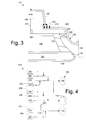
- Fig. 3 shows a portion of a fuel nozzle 100 as may be described herein.
- the fuel nozzle 100 may be used in a combustor 110 such as the combustor 25 described above. Any number of the fuel nozzles 100 may be used within the combustor 110. Fuel nozzles of differing configurations may be used herein.
- the fuel nozzle 100 may include a pilot or main passage 120.
- the main passage 120 may be an elongated tube 130 with one or more injection holes 140 thereon at a downstream end 145 thereof.
- the injection holes 140 may have differing configurations and locations.
- the main passage may flow natural gas, liquid fuels, or syngas. Different types of fuels may be used at different times and/or under different operating conditions. Other types of fuels, other components, and other configurations may be used herein.
- the secondary passages 150 Surrounding the main passage 120 may be one or more secondary passages 150.
- the secondary passages 150 also may be elongated tubes 160 with one or more injection holes 170 at the downstream end 145 thereof.
- the injection holes 170 may have differing configurations and locations.
- the secondary passages 150 may provide a flow of purge air, a flow of an inert purge such as nitrogen, or a flow of a low BTU fuel such as a syngas depending upon the mode of operation. Different types of fluid flows may be used at different times and/or under different operating conditions. Other types of fluid flows, other components, and other configurations may be used herein.
- the fuel nozzle 100 also may include an inert or a tertiary passage 180.
- the tertiary passage 180 may surround the secondary passage 150.
- the tertiary passage 180 may include an air plenum 190.
- the air plenum 190 may be defmed between a baffle plate 195 and a cover-ring 200 or otherwise.
- the baffle plate 195 may terminate about a shroud 210.
- the shroud 210 may be separated from a nozzle collar 220 and the like by a number of piston rings 230. Any number of piston rings 230 may be used herein.
- the shroud 210 and/or the nozzle collar 220 may define a flow channel 240 therein in communication with the air plenum 190 on one end and one or more flow holes 250 on another.
- the tertiary passage 180 may provide a flow of inert diluent, a flow of purge air, a flow of an inert purge such as nitrogen, or a flow of a low BTU fuel such as a syngas.
- Different types of fluid flows may be used at different times and/or under different operating conditions. Other types of fluid flows, other components, and other configurations may be used herein.
- Fig. 4 shows a fueling scheme for the fuel nozzle 100 of the combustor 110.
- the main passage 120 may be in communication with a natural gas source 260 with a flow of natural gas 265 therein and a low BTU fuel source 270 with a flow of low BTU fuel 275 therein.
- a liquid fuel source also may be used herein.
- the secondary passages 150 may be in communication with the low BTU fuel source 270, a purge air source 280 with a flow of purge air 285 therein, and a nitrogen purge source 290 with a flow of nitrogen 295 therein.
- the tertiary passage 180 may be in communication with the low BTU fuel source 270, the purge air source 280, the nitrogen purge source 290, and a diluent source 300 with a flow of diluent 305 therein.
- Various types of control valves 310 and by-pass lines 320 also may be used herein.
- Other types of flows, other components, and other configurations also may be used herein.
- multiple low BTU fuel sources 270 are shown in the drawings, it will be understood that a single source or multiple sources may be used for each of the fluid flow described herein.
- the low BTU fuel source is intended to mean a fuel that has lower calorific value than conventional gaseous, liquid, or solid fuels (e.g., methane) but which has a calorific value that is high enough to create a combustible mixture and allow continuous burning.
- Low BTU fuels may be characterized as having a calorific range between 90 and 700 BTU/scf (British thermal units per standard cubic feet).
- the calorific value is a fuel property that defines the amount of heat released when burned.
- Low BTU fuels may have a higher concentration of constituents with no or low calorific value (e.g., carbon monoxide, carbon dioxide, nitrogen, and so forth). Other types of fuel ranges may be used herein.
- the fuel nozzle 100 thus may have many different modes of operation.
- natural gas may be provided to the main passage 120 and purge air may be provided to the secondary passage 150 and tertiary passage 180.
- purge air may be provided to the secondary passage 150
- diluent may be provided to the tertiary passage 180.
- Liquid fuel operations also may be used herein.
- natural gas may be supplied to the main passage 120, purge air may be provided to the secondary passage 150, and the low BTU fuel may be provided to the tertiary passages 180.
- the low BTU fuel may be provided to the main passage 120, purge air may be provided to the secondary passage 150, and the low BTU fuel may be provided to the tertiary passage 180.
- the low BTU fuel may be provided to the main passage 120, nitrogen may be provided to the secondary passage, and the low BTU fuel may be provided to the tertiary passage 180.
- the low BTU fuel may be provided to the main passage, the secondary passage, and the tertiary passage 180.
- Other options may be used herein.
- natural gas may be provided to the main passage 120, purge air may be provided to the secondary passage 150, and nitrogen may be provided to the tertiary passage 180.
- natural gas may be provided to the main passage 120, purge air may be provided to the secondary passages 150, and the low BTU fuel may be provided to the tertiary passage 180.
- natural gas may be provided to the main passage 120, nitrogen may be provided to the secondary passage 150, and the low BTU fuel may be provided to the tertiary passage 180.
- natural gas may be provided to the main passage 120 while the low BTU fuel may be provided to the secondary passage 150 and the tertiary passage 180.
- the low BTU fuel may be provided to the main passage 120, the secondary passage 150, and the tertiary passage 180.
- Other options also may be used herein.
- modes of operation include diluent injection for suppression of nitrogen oxides with natural gas, liquid fuel, medium BTU fuels, low BTU fuels, and ultra low BTU fuels. Further, a number of co-fire modes also may be used herein. Other modes of operation and combinations thereof may be used herein.
- the fuel nozzle 100 thus may control combustion dynamics by varying the pressure ratios in the secondary passage 150 and the tertiary passage 180 when operating on low BTU fuels, including ultra low BTU fuel.
- the fuel nozzle 100 requires less inert purge flow (nitrogen) so as to help dynamics abatement during mode transfer.
- the fuel nozzle 100 also may lower the risk of flame holding by active control of the flows at the downstream end 145 and within the combustion zone 65.
- the fuel nozzle 100 also allows turndown extensions with the use of the low and the ultra low BTU fuels and the like.
- combustors 100 may be used herein.
- can, can annular, or annular types of combustion systems may be used herein.
- Liquid fuel, natural gas, medium BTU fuels, low BTU fuels, and ultra low BTU fuels, or any combination thereof may be used herein.
Landscapes
- Engineering & Computer Science (AREA)
- Chemical & Material Sciences (AREA)
- Combustion & Propulsion (AREA)
- Mechanical Engineering (AREA)
- General Engineering & Computer Science (AREA)
- Feeding And Controlling Fuel (AREA)
Abstract
Description
- The present application relates generally to gas turbine engines and more particularly relates to a fuel flexible combustor fuel nozzle for use with ultra low to medium BTU fuel applications as well as other types of fuels and/or combinations of fuels.
- Modem gas turbine engines may offer fuel flexibility in that both natural gas and highly reactive fuels such as syngas and the like may be used. The use of a diverse fuel spectrum provides increased operational flexibility, cost control, plant efficiency, and/or improved emissions characteristics. Such fuel flexibility provides customers with the ability to select a fuel source based upon availability, price, and other variables.
- The combustor of the gas turbine engine, however, must be able to accommodate the significant differences between the characteristics of natural gas and syngas such as in Wobbe number and fuel reactivity. For example, the volumetric flow rate for syngas may be more than double the volumetric flow rate for natural gas for the same combustion temperature. As such, the syngas fuel pressure ratios may be extremely high. Moreover, the use of such highly reactive fuels may lead to flame holding and possible nozzle damage.
- There is a desire for improved combustor fuel nozzle designs that provide fuel flexibility to accommodate a variety of fuels. The combustor fuel nozzle should be able to accommodate both natural gas and syngas without limiting durability or efficiency. The combustor fuel nozzle preferably provides syngas combustion with comparable performance to natural gas combustion in terms of flow, mixing, dynamics, and emission patterns.
- The present invention provides a flexible combustor fuel nozzle. The flexible combustor fuel nozzle includes a main passage in communication with a source of natural gas and a source of low BTU fuel, a secondary passage surrounding the main passage and in communication with the source of low BTU fuel and a source of purge air, and a tertiary passage surrounding the secondary passage and in communication with the source of low BTU fuel, the source of purge air, and a source of diluent.
- The present invention further provides a method of operating a combustor fuel nozzle. The method includes the steps of flowing a natural gas or a low BTU fuel from a main passage, flowing the low BTU fuel or a purge air flow from a secondary passage, and flowing the low BTU fuel, the purge air flow, or a diluent flow from a tertiary passage.
- These and other features of the present application and the resultant patent will become apparent to one of ordinary skill in the art upon review of the following detailed description when taken in conjunction with the several drawings and the appended claims.
- Embodiments of the present invention will now be described, by way of example only, with reference to the accompanying drawings in which:
-
Fig. 1 is a schematic view of a gas turbine engine. -
Fig. 2 is a side cross-sectional view of a combustor of the gas turbine engine. -
Fig. 3 is a side cross-sectional view of a portion of a fuel nozzle as may be described herein. -
Fig. 4 is a schematic of a combustor fuel scheme using the fuel nozzle ofFig. 3 . - Referring now to the drawings, in which like numerals refer to like elements throughout the several views,
Fig. 1 shows a schematic view ofgas turbine engine 10 as may be used herein. Thegas turbine engine 10 may include acompressor 15. Thecompressor 15 compresses an incoming flow ofair 20. Thecompressor 15 delivers the compressed flow ofair 20 to acombustor 25. Thecombustor 25 mixes the compressed flow ofair 20 with a compressed flow offuel 30 and ignites the mixture to create a flow ofcombustion gases 35. Although only asingle combustor 25 is shown, thegas turbine engine 10 may include any number ofcombustors 25. The flow ofcombustion gases 35 is in turn delivered to aturbine 40. The flow ofcombustion gases 35 drives theturbine 40 so as to produce mechanical work. The mechanical work produced in theturbine 40 drives thecompressor 15 via ashaft 45 and anexternal load 50 such as an electrical generator and the like. Other components and other configurations may be used herein. - The
gas turbine engine 10 may use natural gas, various types of syngas, and/or other types of fuels. Thegas turbine engine 10 may be any one of a number of different gas turbine engines, including but not limited to, those offered by General Electric Company of Schenectady, New York and the like. Thegas turbine engine 10 may have different configurations and may use other types of components. Other types of gas turbine engines also may be used herein. Multiple gas turbine engines, other types of turbines, and other types of power generation equipment also may be used herein together. -
Fig. 2 shows an example of thecombustor 25. As is shown, thecombustor 25 includes a number offuel nozzles 55. Any number of thefuel nozzles 55 may be used herein. Thefuel nozzles 55 may be positioned within an endcover 60 or other type of support structure. As described above, thefuel nozzles 55 ignite the flow ofair 20 and the flow offuel 30 to create the flow ofcombustion gases 35 within acombustion zone 65 for use in driving theturbine 40. Other components and other configurations may be used herein. -
Fig. 3 shows a portion of afuel nozzle 100 as may be described herein. Thefuel nozzle 100 may be used in acombustor 110 such as thecombustor 25 described above. Any number of thefuel nozzles 100 may be used within thecombustor 110. Fuel nozzles of differing configurations may be used herein. - The
fuel nozzle 100 may include a pilot ormain passage 120. Themain passage 120 may be anelongated tube 130 with one ormore injection holes 140 thereon at adownstream end 145 thereof. Theinjection holes 140 may have differing configurations and locations. The main passage may flow natural gas, liquid fuels, or syngas. Different types of fuels may be used at different times and/or under different operating conditions. Other types of fuels, other components, and other configurations may be used herein. - Surrounding the
main passage 120 may be one or moresecondary passages 150. Thesecondary passages 150 also may beelongated tubes 160 with one ormore injection holes 170 at thedownstream end 145 thereof. Theinjection holes 170 may have differing configurations and locations. Thesecondary passages 150 may provide a flow of purge air, a flow of an inert purge such as nitrogen, or a flow of a low BTU fuel such as a syngas depending upon the mode of operation. Different types of fluid flows may be used at different times and/or under different operating conditions. Other types of fluid flows, other components, and other configurations may be used herein. - The
fuel nozzle 100 also may include an inert or atertiary passage 180. Thetertiary passage 180 may surround thesecondary passage 150. Thetertiary passage 180 may include anair plenum 190. Theair plenum 190 may be defmed between abaffle plate 195 and a cover-ring 200 or otherwise. Thebaffle plate 195 may terminate about ashroud 210. Theshroud 210 may be separated from anozzle collar 220 and the like by a number of piston rings 230. Any number ofpiston rings 230 may be used herein. Theshroud 210 and/or thenozzle collar 220 may define aflow channel 240 therein in communication with theair plenum 190 on one end and one or more flow holes 250 on another. Thetertiary passage 180 may provide a flow of inert diluent, a flow of purge air, a flow of an inert purge such as nitrogen, or a flow of a low BTU fuel such as a syngas. Different types of fluid flows may be used at different times and/or under different operating conditions. Other types of fluid flows, other components, and other configurations may be used herein. -
Fig. 4 shows a fueling scheme for thefuel nozzle 100 of thecombustor 110. As is shown, themain passage 120 may be in communication with anatural gas source 260 with a flow ofnatural gas 265 therein and a lowBTU fuel source 270 with a flow oflow BTU fuel 275 therein. A liquid fuel source also may be used herein. Thesecondary passages 150 may be in communication with the lowBTU fuel source 270, apurge air source 280 with a flow ofpurge air 285 therein, and anitrogen purge source 290 with a flow ofnitrogen 295 therein. Thetertiary passage 180 may be in communication with the lowBTU fuel source 270, thepurge air source 280, thenitrogen purge source 290, and adiluent source 300 with a flow ofdiluent 305 therein. Various types ofcontrol valves 310 and by-pass lines 320 also may be used herein. Other types of flows, other components, and other configurations also may be used herein. Although, for example, multiple lowBTU fuel sources 270 are shown in the drawings, it will be understood that a single source or multiple sources may be used for each of the fluid flow described herein. - The low BTU fuel source is intended to mean a fuel that has lower calorific value than conventional gaseous, liquid, or solid fuels (e.g., methane) but which has a calorific value that is high enough to create a combustible mixture and allow continuous burning. Low BTU fuels may be characterized as having a calorific range between 90 and 700 BTU/scf (British thermal units per standard cubic feet). The calorific value is a fuel property that defines the amount of heat released when burned. Low BTU fuels may have a higher concentration of constituents with no or low calorific value (e.g., carbon monoxide, carbon dioxide, nitrogen, and so forth). Other types of fuel ranges may be used herein.
- The
fuel nozzle 100 thus may have many different modes of operation. For example, in an unabated natural gas mode, natural gas may be provided to themain passage 120 and purge air may be provided to thesecondary passage 150 andtertiary passage 180. In an abated mode, natural gas may be provided to themain passage 120, purge air may be provided to thesecondary passage 150, and diluent may be provided to thetertiary passage 180. Liquid fuel operations also may be used herein. - In an abated transfer mode from natural gas or liquid fuel to syngas, many different options may be used herein. In a first option, natural gas may be supplied to the
main passage 120, purge air may be provided to thesecondary passage 150, and the low BTU fuel may be provided to thetertiary passages 180. In a second option, the low BTU fuel may be provided to themain passage 120, purge air may be provided to thesecondary passage 150, and the low BTU fuel may be provided to thetertiary passage 180. In a third option, the low BTU fuel may be provided to themain passage 120, nitrogen may be provided to the secondary passage, and the low BTU fuel may be provided to thetertiary passage 180. In a fourth option, the low BTU fuel may be provided to the main passage, the secondary passage, and thetertiary passage 180. Other options may be used herein. - In an unabated transfer mode, several different options also may be used. In a first option, natural gas may be provided to the
main passage 120, purge air may be provided to thesecondary passage 150, and nitrogen may be provided to thetertiary passage 180. In a second option, natural gas may be provided to themain passage 120, purge air may be provided to thesecondary passages 150, and the low BTU fuel may be provided to thetertiary passage 180. In a third option, natural gas may be provided to themain passage 120, nitrogen may be provided to thesecondary passage 150, and the low BTU fuel may be provided to thetertiary passage 180. In a fourth option, natural gas may be provided to themain passage 120 while the low BTU fuel may be provided to thesecondary passage 150 and thetertiary passage 180. In a fifth option, the low BTU fuel may be provided to themain passage 120, thesecondary passage 150, and thetertiary passage 180. Other options also may be used herein. - Other modes of operation include diluent injection for suppression of nitrogen oxides with natural gas, liquid fuel, medium BTU fuels, low BTU fuels, and ultra low BTU fuels. Further, a number of co-fire modes also may be used herein. Other modes of operation and combinations thereof may be used herein.
- The
fuel nozzle 100 thus may control combustion dynamics by varying the pressure ratios in thesecondary passage 150 and thetertiary passage 180 when operating on low BTU fuels, including ultra low BTU fuel. Thefuel nozzle 100 requires less inert purge flow (nitrogen) so as to help dynamics abatement during mode transfer. Thefuel nozzle 100 also may lower the risk of flame holding by active control of the flows at thedownstream end 145 and within thecombustion zone 65. Thefuel nozzle 100 also allows turndown extensions with the use of the low and the ultra low BTU fuels and the like. - Different types of
combustors 100 may be used herein. For example, can, can annular, or annular types of combustion systems may be used herein. Liquid fuel, natural gas, medium BTU fuels, low BTU fuels, and ultra low BTU fuels, or any combination thereof may be used herein. - It should be apparent that the foregoing relates only to certain embodiments of the present application and the resultant patent. Numerous changes and modifications may be made herein by one of ordinary skill in the art without departing from the general spirit and scope of the invention as defined by the following claims and the equivalents thereof.
Claims (15)
- A flexible combustor fuel nozzle (100), comprising:a main passage (120);the main passage (120) in communication with a source of natural gas (260) and a source of low BTU fuel (270);a secondary passage (150) surrounding the main passage (120);the secondary passage (150) in communication with the source of low BTU fuel (270) and a source of purge air (280); anda tertiary passage (180) surrounding the secondary passage (150);the tertiary passage (180) in communication with the source of low BTU fuel (270), the source of purge air (280), and a source of diluent (300).
- The flexible combustor fuel nozzle (100) of claim 1, wherein the main passage (120) comprises an elongated tube (130) and one or more injection holes (140) at a downstream end (145) thereof.
- The flexible combustor fuel nozzle (100) of claim 1 or 2, wherein the secondary passage (150) comprises an elongated tube (160) and one or more injection holes (170) at a downstream end (145) thereof.
- The flexible combustor fuel nozzle (100) of any of claims 1 to 3, further comprising a plurality of secondary nozzles (150).
- The flexible combustor fuel nozzle (100) of any of claims 1 to 4, wherein the tertiary passage (180) comprises a shroud (210) and a plurality of piston rings (230).
- The flexible combustor fuel nozzle (100) of any of claims 1 to 5, wherein the tertiary passage (180) comprises an air plenum (190) therein.
- The flexible combustor fuel nozzle (100) of claim 6, wherein the tertiary passage (180) comprises a flow channel (240) extending from the air plenum (190) to one or more flow holes (250).
- The flexible combustor fuel nozzle (100) of any preceding claim, further comprising a source of nitrogen (290) in communication with the secondary passage (150) and the tertiary passage (180).
- The flexible combustor fuel nozzle (100) of any preceding claim, wherein the main passage (120) comprises a flow of natural gas (265) or a flow of low BTU fuel (275) therein.
- The flexible combustor fuel nozzle (100) of any preceding claim, wherein the secondary passage (150) comprises a flow of low BTU fuel (275) or a flow of purge air therein (285).
- The flexible combustor fuel nozzle (100) of any preceding claim, wherein the tertiary passage (180) comprises a flow of low BTU fuel (275), a flow of purge air (285), or a flow of diluent (305) therein.
- The flexible combustor fuel nozzle (100) of any preceding claim, further comprising a by-pass line (320) positioned between the main passage (120) and the secondary passage (150) and/or between the secondary passage (150) and the tertiary passage (180).
- The flexible combustor fuel nozzle (100) of any preceding claim, further comprising one or more control valves (310) positioned on the main passage (120), the secondary passage (150), and/or the tertiary passage (180).
- The flexible combustor fuel nozzle (100) of any preceding claim, further comprising a nozzle collar (220) at a downstream end (145) thereof.
- A method of operating a combustor fuel nozzle (100), comprising:flowing a natural gas (265) or a low BTU fuel (275) from a main passage (120);flowing the low BTU fuel (275) or a purge air flow (285) from a secondary passage (150); andflowing the low BTU fuel (275), the purge air flow (285), or a diluent flow (305) from a tertiary passage (180).
Applications Claiming Priority (1)
| Application Number | Priority Date | Filing Date | Title |
|---|---|---|---|
| US13/111,036 US8448442B2 (en) | 2011-05-19 | 2011-05-19 | Flexible combustor fuel nozzle |
Publications (1)
| Publication Number | Publication Date |
|---|---|
| EP2525153A1 true EP2525153A1 (en) | 2012-11-21 |
Family
ID=46085845
Family Applications (1)
| Application Number | Title | Priority Date | Filing Date |
|---|---|---|---|
| EP12168243A Withdrawn EP2525153A1 (en) | 2011-05-19 | 2012-05-16 | Flexible combustor fuel nozzle |
Country Status (3)
| Country | Link |
|---|---|
| US (1) | US8448442B2 (en) |
| EP (1) | EP2525153A1 (en) |
| CN (1) | CN102788369B (en) |
Cited By (1)
| Publication number | Priority date | Publication date | Assignee | Title |
|---|---|---|---|---|
| WO2016063222A1 (en) * | 2014-10-20 | 2016-04-28 | A.S.EN. ANSALDO SVILUPPO ENERGIA S.r.l. | Gas turbine unit with multifluid fuel supply and method of supplying a burner of a gas turbine unit |
Families Citing this family (3)
| Publication number | Priority date | Publication date | Assignee | Title |
|---|---|---|---|---|
| US10480403B2 (en) | 2016-02-22 | 2019-11-19 | King Fahd University Of Petroleum And Minerals | Combustor with adjustable swirler and a combustion system |
| CN107166435A (en) * | 2017-07-07 | 2017-09-15 | 西安富兰克石油技术有限公司 | A kind of multi fuel nozzle, fuel spray system and its turbogenerator |
| US11680549B2 (en) * | 2019-10-04 | 2023-06-20 | Hamilton Sundstrand Corporation | Fluid injection systems for fluid line purging |
Citations (4)
| Publication number | Priority date | Publication date | Assignee | Title |
|---|---|---|---|---|
| US5451160A (en) * | 1991-04-25 | 1995-09-19 | Siemens Aktiengesellschaft | Burner configuration, particularly for gas turbines, for the low-pollutant combustion of coal gas and other fuels |
| EP1391657A2 (en) * | 2002-08-22 | 2004-02-25 | Hitachi, Ltd. | Gas turbine combustor, combustion method of the gas turbine combustor, and method of remodeling a gas turbine combustor |
| US20100089021A1 (en) * | 2008-10-14 | 2010-04-15 | General Electric Company | Method and apparatus of introducing diluent flow into a combustor |
| US20100281876A1 (en) * | 2009-05-05 | 2010-11-11 | Abdul Rafey Khan | Fuel blanketing by inert gas or less reactive fuel layer to prevent flame holding in premixers |
Family Cites Families (6)
| Publication number | Priority date | Publication date | Assignee | Title |
|---|---|---|---|---|
| US7536862B2 (en) * | 2005-09-01 | 2009-05-26 | General Electric Company | Fuel nozzle for gas turbine engines |
| US20100089020A1 (en) | 2008-10-14 | 2010-04-15 | General Electric Company | Metering of diluent flow in combustor |
| US9121609B2 (en) * | 2008-10-14 | 2015-09-01 | General Electric Company | Method and apparatus for introducing diluent flow into a combustor |
| US20100089022A1 (en) | 2008-10-14 | 2010-04-15 | General Electric Company | Method and apparatus of fuel nozzle diluent introduction |
| US8220272B2 (en) | 2008-12-04 | 2012-07-17 | General Electric Company | Combustor housing for combustion of low-BTU fuel gases and methods of making and using the same |
| US8359870B2 (en) * | 2009-05-12 | 2013-01-29 | General Electric Company | Automatic fuel nozzle flame-holding quench |
-
2011
- 2011-05-19 US US13/111,036 patent/US8448442B2/en active Active
-
2012
- 2012-05-16 EP EP12168243A patent/EP2525153A1/en not_active Withdrawn
- 2012-05-18 CN CN201210165235.7A patent/CN102788369B/en not_active Expired - Fee Related
Patent Citations (4)
| Publication number | Priority date | Publication date | Assignee | Title |
|---|---|---|---|---|
| US5451160A (en) * | 1991-04-25 | 1995-09-19 | Siemens Aktiengesellschaft | Burner configuration, particularly for gas turbines, for the low-pollutant combustion of coal gas and other fuels |
| EP1391657A2 (en) * | 2002-08-22 | 2004-02-25 | Hitachi, Ltd. | Gas turbine combustor, combustion method of the gas turbine combustor, and method of remodeling a gas turbine combustor |
| US20100089021A1 (en) * | 2008-10-14 | 2010-04-15 | General Electric Company | Method and apparatus of introducing diluent flow into a combustor |
| US20100281876A1 (en) * | 2009-05-05 | 2010-11-11 | Abdul Rafey Khan | Fuel blanketing by inert gas or less reactive fuel layer to prevent flame holding in premixers |
Cited By (1)
| Publication number | Priority date | Publication date | Assignee | Title |
|---|---|---|---|---|
| WO2016063222A1 (en) * | 2014-10-20 | 2016-04-28 | A.S.EN. ANSALDO SVILUPPO ENERGIA S.r.l. | Gas turbine unit with multifluid fuel supply and method of supplying a burner of a gas turbine unit |
Also Published As
| Publication number | Publication date |
|---|---|
| US20120291448A1 (en) | 2012-11-22 |
| CN102788369A (en) | 2012-11-21 |
| CN102788369B (en) | 2016-01-20 |
| US8448442B2 (en) | 2013-05-28 |
Similar Documents
| Publication | Publication Date | Title |
|---|---|---|
| US8112999B2 (en) | Turbomachine injection nozzle including a coolant delivery system | |
| EP2657611B1 (en) | System for supplying fuel to a combustor | |
| EP2657483B1 (en) | System for supplying fuel to a combustor | |
| US20190162414A1 (en) | Gas turbine combustor | |
| US8113002B2 (en) | Combustor burner vanelets | |
| EP2557362A2 (en) | Turbomachine combustor assembly | |
| EP2520857A1 (en) | A Combustor Nozzle And Method For Supplying Fuel To A Combustor | |
| EP2657605A2 (en) | System and Method for Supplying a Working Fluid to a Combustor | |
| EP2664854B1 (en) | Secondary combustion system | |
| US20120006033A1 (en) | Combustor and Combustor Screech Mitigation Methods | |
| CN102809176A (en) | Aerodynamic fuel nozzle | |
| JP2018508735A (en) | System and method for high volume oxidant flow in a gas turbine engine with exhaust recirculation | |
| JP2011064447A (en) | Radial inlet guide vane for combustor | |
| US8613187B2 (en) | Fuel flexible combustor systems and methods | |
| US8448442B2 (en) | Flexible combustor fuel nozzle | |
| EP2592349A2 (en) | Combustor and method for supplying fuel to a combustor | |
| US9360220B2 (en) | Micro-mixer nozzle | |
| US20130227928A1 (en) | Fuel nozzle assembly for use in turbine engines and method of assembling same | |
| EP2626632A2 (en) | Fuel injection assembly for use in turbine engines and method of assembling same | |
| US9500367B2 (en) | Combustion casing manifold for high pressure air delivery to a fuel nozzle pilot system | |
| CN111623373A (en) | Sequential combustor for a gas turbine, method of operating the same and method of refurbishing the same |
Legal Events
| Date | Code | Title | Description |
|---|---|---|---|
| PUAI | Public reference made under article 153(3) epc to a published international application that has entered the european phase |
Free format text: ORIGINAL CODE: 0009012 |
|
| AK | Designated contracting states |
Kind code of ref document: A1 Designated state(s): AL AT BE BG CH CY CZ DE DK EE ES FI FR GB GR HR HU IE IS IT LI LT LU LV MC MK MT NL NO PL PT RO RS SE SI SK SM TR |
|
| AX | Request for extension of the european patent |
Extension state: BA ME |
|
| 17P | Request for examination filed |
Effective date: 20130521 |
|
| GRAP | Despatch of communication of intention to grant a patent |
Free format text: ORIGINAL CODE: EPIDOSNIGR1 |
|
| INTG | Intention to grant announced |
Effective date: 20161215 |
|
| GRAS | Grant fee paid |
Free format text: ORIGINAL CODE: EPIDOSNIGR3 |
|
| GRAJ | Information related to disapproval of communication of intention to grant by the applicant or resumption of examination proceedings by the epo deleted |
Free format text: ORIGINAL CODE: EPIDOSDIGR1 |
|
| GRAL | Information related to payment of fee for publishing/printing deleted |
Free format text: ORIGINAL CODE: EPIDOSDIGR3 |
|
| INTC | Intention to grant announced (deleted) | ||
| 17Q | First examination report despatched |
Effective date: 20170322 |
|
| STAA | Information on the status of an ep patent application or granted ep patent |
Free format text: STATUS: THE APPLICATION IS DEEMED TO BE WITHDRAWN |
|
| 18D | Application deemed to be withdrawn |
Effective date: 20170802 |