EP1391657A2 - Gas turbine combustor, combustion method of the gas turbine combustor, and method of remodeling a gas turbine combustor - Google Patents
Gas turbine combustor, combustion method of the gas turbine combustor, and method of remodeling a gas turbine combustor Download PDFInfo
- Publication number
- EP1391657A2 EP1391657A2 EP03005446A EP03005446A EP1391657A2 EP 1391657 A2 EP1391657 A2 EP 1391657A2 EP 03005446 A EP03005446 A EP 03005446A EP 03005446 A EP03005446 A EP 03005446A EP 1391657 A2 EP1391657 A2 EP 1391657A2
- Authority
- EP
- European Patent Office
- Prior art keywords
- burner
- premixed
- flame
- fuel
- disposed
- Prior art date
- Legal status (The legal status is an assumption and is not a legal conclusion. Google has not performed a legal analysis and makes no representation as to the accuracy of the status listed.)
- Granted
Links
Images


Classifications
-
- F—MECHANICAL ENGINEERING; LIGHTING; HEATING; WEAPONS; BLASTING
- F23—COMBUSTION APPARATUS; COMBUSTION PROCESSES
- F23R—GENERATING COMBUSTION PRODUCTS OF HIGH PRESSURE OR HIGH VELOCITY, e.g. GAS-TURBINE COMBUSTION CHAMBERS
- F23R3/00—Continuous combustion chambers using liquid or gaseous fuel
- F23R3/28—Continuous combustion chambers using liquid or gaseous fuel characterised by the fuel supply
- F23R3/36—Supply of different fuels
-
- F—MECHANICAL ENGINEERING; LIGHTING; HEATING; WEAPONS; BLASTING
- F23—COMBUSTION APPARATUS; COMBUSTION PROCESSES
- F23R—GENERATING COMBUSTION PRODUCTS OF HIGH PRESSURE OR HIGH VELOCITY, e.g. GAS-TURBINE COMBUSTION CHAMBERS
- F23R3/00—Continuous combustion chambers using liquid or gaseous fuel
- F23R3/02—Continuous combustion chambers using liquid or gaseous fuel characterised by the air-flow or gas-flow configuration
- F23R3/16—Continuous combustion chambers using liquid or gaseous fuel characterised by the air-flow or gas-flow configuration with devices inside the flame tube or the combustion chamber to influence the air or gas flow
- F23R3/18—Flame stabilising means, e.g. flame holders for after-burners of jet-propulsion plants
-
- F—MECHANICAL ENGINEERING; LIGHTING; HEATING; WEAPONS; BLASTING
- F23—COMBUSTION APPARATUS; COMBUSTION PROCESSES
- F23R—GENERATING COMBUSTION PRODUCTS OF HIGH PRESSURE OR HIGH VELOCITY, e.g. GAS-TURBINE COMBUSTION CHAMBERS
- F23R3/00—Continuous combustion chambers using liquid or gaseous fuel
- F23R3/28—Continuous combustion chambers using liquid or gaseous fuel characterised by the fuel supply
- F23R3/286—Continuous combustion chambers using liquid or gaseous fuel characterised by the fuel supply having fuel-air premixing devices
-
- F—MECHANICAL ENGINEERING; LIGHTING; HEATING; WEAPONS; BLASTING
- F23—COMBUSTION APPARATUS; COMBUSTION PROCESSES
- F23R—GENERATING COMBUSTION PRODUCTS OF HIGH PRESSURE OR HIGH VELOCITY, e.g. GAS-TURBINE COMBUSTION CHAMBERS
- F23R3/00—Continuous combustion chambers using liquid or gaseous fuel
- F23R3/28—Continuous combustion chambers using liquid or gaseous fuel characterised by the fuel supply
- F23R3/34—Feeding into different combustion zones
- F23R3/343—Pilot flames, i.e. fuel nozzles or injectors using only a very small proportion of the total fuel to insure continuous combustion
Definitions
- the present invention relates to a gas turbine combustor, a combustion method of the gas turbine combustor and a method of remodeling a gas turbine combustor.
- Patent Documents 1 and 2 Examples of conventional gas turbine combustors using both a premixed combustion method and a diffusion combustion method are disclosed by Patent Documents 1 and 2, etc.
- pre-evaporation mixing is made using liquid fuel
- pre-evaporation cannot be made because air temperature at the time of ignition is too low. This requires use of a pilot burner, and the above-described problem with flame transmission becomes more significant.
- an object of the present invention is to provide a gas turbine combustor that makes adequate combustion with a combustor for which gas fuel and/or liquid fuel can be used, and that is excellent in minimizing NOx, a combustion method of the gas turbine combustor, and a method of remodeling a gas turbine combustor.
- Flame stabilizers are arranged radially in the exit of the premixed combustion burner, and air is spouted out at the position outside the pilot burner and/or inside said premixed combustion burner.
- a gas turbine combustor can comprise a pilot burner, a premixed combustion burner disposed on the outer circumference of the pilot burner, and/or a combustor liner in an approximately cylindrical shape which is disposed on the downstream side of the premixed combustion burner, and which defines a combustion chamber in the inner wall.
- the gas turbine combustor can comprise flame stabilizers radially disposed at the exit of the premixed combustion burner, and/or a plurality of air nozzles located inside the premixed combustion burner, which spout out air into the combustion chamber.
- the pilot burner can be provided with a fuel injection means which injects at least one of gas fuel and liquid fuel.
- flame stabilizers are radially disposed at the exit of the premixing burner, fuel of the pilot burner can form flame on the flame stabilizing surface.
- premixed flame can be stabilized, and when liquid fuel is used, mixing of air ejected from the premixed combustion burner with fuel of the pilot burner can be promoted, preventing extension of diffusion flame.
- the air nozzle between the pilot burner and premixed combustion burner can prevent a rise in the temperature of the flame stabilizing surface, and/or stabilizes diffusion flame.
- a temperature distribution at the exit of the combustor can be uniformed by providing radially disposed flame stabilizers. This further contributes to protection of the turbine.
- the radially disposed flame stabilizers can have a shape in which a plurality of projections project from the inner circumference side to the outer circumference side (outside in the radial direction) of the flame stabilizers, as viewed from the combustion chamber to the pilot burner.
- the gas turbine combustor can be provided with the flame stabilizers radially disposed at the exit of the premixed combustion burner and/or a cross-fire tube provided with an opening which is disposed in the side wall of the liner and which is circumferentially aligned with at least one of the flame stabilizers.
- the cross-fire tube can be connected to the side wall of the combustor liner by way of the opening which is circumferentially aligned with one of the cross-fire tubes as described above.
- the flame stabilizers can be each inclined so that the outer circumferential side is positioned on the downstream side relative to the inner circumferential side at the edge on the downstream side, and desirably, the inclination angle relative to the center axis of the combustor is set to 30° or more and 60° or less.
- premixed combustion gas on the outer circumferential side deflects in the direction in which the premixed combustion gas on the outer circumferential side converges to the axial center of the combustor after passing through the edge downstream of the flame stabilizers, causing diffusion combustion gas on the inner circumferential side to be diluted and mixed sufficiently.
- extension of diffusion flame is prevented to reduce production of NOx, and occurrence of combustion temperature deviation at the combustor exit is prevented, protecting damage to turbine blades.
- the radially disposed flame stabilizers can be slanted so that the outer circumferential side thereof is positioned on the downstream side thereof relative to the inner circumferential side at edges an the downstream side. This arrangement is effective in further improving stability of flame.
- the inner circumference of the flame stabilizers can be fixed to the premixed combustion burner, and the edges on the outer circumferential side of the flame stabilizers can be separated from the premixed combustion burner outer circumferential wall.
- stress caused by thermal expansion of the flame stabilizers and the like can be released.
- premixture or air ejected into the combustion chamber through the space between the edge on the downstream side of the flame stabilizers and premixed combustion burner outer circumferential wall can prevent a rise in the temperature of combustion chamber sidewall due to diffusion flame.
- the air nozzle can be configured in such a manner to spout out air swirlingly.
- air is spread by the swirling, improving cooling of the flame stabilizing surface.
- expansion of a swirl flow range made by the swirling air further stabilizes diffusion flame.
- a slit can be provided outside the air nozzle and inside the premixed combustion burner.
- the slit is provided with a means of allowing air to flow toward the flame stabilizers.
- the air inlet portion or the air outlet portion of the pilot burner can be provided with a nozzle capable of ejecting water or steam. This nozzle supplies water or steam to near the fuel injection unit at the time of diffusion combustion of liquid fuel, effectively reducing NOx.
- a partition can be provided to divide a passage of the premixed combustion burner in the circumferential direction.
- the drift of premixture (or air for premixing) which flows in the circumferential direction in the premixed combustion burner is suppressed.
- deviations of flow velocity and fuel concentration at the exit of the premixed combustion burner are reduced, causing NOx to be reduced and preventing flashback.
- the flame stabilizers can be each disposed in such a manner as to be positioned between the partition and a partition adjacent thereto.
- the circumferential drift of premixture (or air for premixing) which flows on the circumferential side of the flame stabilizer is suppressed.
- deviations of flow velocity and fuel concentration at the exit of the premixed combustion burner are reduced, causing NOx to be reduced and preventing flashback.
- the partition can be so arranged as to project into the combustion chamber toward the downstream side of the flame stabilizers. With this arrangement, a stabilized premixed swirl flow can be formed downstream of the flame stabilizing surface, improving stability of the premixing flame.
- the flame stabilizers can be provided with a plurality of nozzles which spout out premixture or air into the combustion chamber. With this structure, flame surface cooling performance is improved. In addition, in a case of the premixture, jet flame on the flame surface can attain the stabilization of premixed flame.
- the edge of the inside wall of the premixed combustion burner can have an inclined surface in which, from the upstream toward the downstream, the cross-sectional area of the premixture or air passage of the premixed combustion chamber is enlarged.
- this inclined surface the premixture or air for premixing is likely to flow into the combustion chamber toward the combustor center axis. This improves mixing performance with diffusion fuel and reduces NOx.
- a fuel nozzle which is capable of directly injecting auxiliary fuel into the combustion chamber can be provided between the flame stabilizers and the pilot burner.
- a nozzle capable of injecting auxiliary fuel and an air Passage are provided between the premixed combustion burner and the pilot burner. With this nozzle and air passage, fuel and air are mixed in advance.
- a second premixture combustion burner is provided to burn the premixture in the combustion chamber.
- a means which is capable of injecting auxiliary fuel to a passage for air or the premixture of the premixed combustion burner is provided between the flame stabilizers disposed radially and the flame stabilizers circumferentially adjacent thereto, and downstream of the fuel injection nozzle of the premixed combustion burner. With this construction, carry-over of diffusion flame and premixed flame can surely be made by charging the auxiliary fuel when burning gas fuel. At the same time, oscillatory combustion can be reduced by dispersing fuel supply positions in the radial direction of the combustion chamber.
- the premixed combustion burner can be configured so that fuel is controllably supplied by a plurality of fuel nozzles divided into several groups.
- the premixed combustion burner has a control method in which a combination of fuel nozzles injecting fuel of fuel nozzles divided in response to gas turbine loads is changed. With this configuration, the total fuel flow can be controlled in response to loads while maintaining the stability of premixed flame at the time of gas fuel combustion.
- FIG. 1 The schematic configuration of a gas turbine combustor according to a first embodiment of the present invention is illustrated in Figs. 1 through 3.
- the combustor is surrounded by an outer casing 1 and an end flange 2, and comprises a combustion chamber 4 surrounded by a liner 3, a diffusion swirl burner 5 which makes diffusion combustion, a premixer 6 which mixes fuel with air to create a premixture, a cross-fire tube 7 which propagates flame to the other combustor at the time of ignition, and a fuel and air supply systems.
- the diffusion swirl burner 5 disposed on the central axis of the combustor circulates diffusion combustion air 12b distributed from combustion air 12a with a swirl blade or swirler 8. Further, the diffusion swirl burner 5 mixes the air with gas 13a or fuel ejected from a liquid fuel nozzle 14 in the combustion chamber 4, forming a diffuse flame.
- a plurality of swirl combustion air nozzles 26 for supplying diffusion combustion air 12b into the combustion chamber 4 is provided on the surrounding of the diffusion swirl burner 5.
- An atomizing air nozzle 27 is provided on the surrounding of liquid fuel nozzle 14a. Liquid fuel for diffusion combustion is atomized by a jet stream of atomizing air supplied from the atomizing air nozzle 27.
- the air inlet of the swirler 8 is provided with water injection nozzles 29. Through these nozzles, water is mixed with the diffusion combustion air 12b so as to supply steam 30 into the combustion chamber.
- the annular premixer 6 provided on the surrounding of the diffusion swirl burner 5 preliminarily mixes fuel ejected from gas 13a which is injected out from a plurality of premixing fuel nozzles 9 with air for premixing 12c distributed from combustion air 12a so as to create a premixture 11.
- Flame stabilizers 10 are provided in the entrance of the combustion chamber 4 located downstream of this premixture 11.
- the flame stabilizers 10 form premixed flame 18 to stabilize flame.
- the plurality of flame stabilizers 10 are disposed radially relative to the central axis of the combustor. Further, each of the flame stabilizers 10 is provided slantly relative to the central axis of the combustor.
- the premixer 6 is provided with partitions 22 so as to circumferentially divide the passage of the premixer 6 from the entrance of the premixer to the upstream of the flame stabilizers 10.
- the flame stabilizers 10 disposed slantly relative to the combustor center axis may, as viewed from the side of the combustor, not only be in a near plane but also be in a slight convex or concave.
- Fig. 2 is a transverse sectional view of two combustors of Fig. 1 coupled through the cross-fire tube 7.
- Eight flame stabilizers 10 are provided for each combustor.
- Each of the flame stabilizers 10 is disposed between and upstream of the partitions 22 of the premixer 6 and between and upstream of the fuel nozzles for premixing.
- Each end of the cross-fire tube 7 is connected to the liner 3 in a radial direction relative to one of the flame stabilizers 10 disposed in the combustor, thereby connecting two combustion chambers 4.
- Fig. 3 is an enlarged sectional view of the diffusion swirl burner of the combustor indicated in Fig. 1. The function of each part and the flowing direction of fluid passing through each part are described hereunder.
- Diffusion combustion air 12b of the diffusion swirl burner is changed to a swirling flow of air by the swirler 8. Further, the air flows into the combustion chamber with a certain inward directional angle directed to the combustor center axis.
- Liquid fuel ejected from the liquid fuel nozzle is atomized by atomizing air. Since this atomized liquid fuel is rapidly mixed with the swirling flow of air, occurrence of soot caused by combustion with an insufficient air is prevented and stable diffuse flame can be formed.
- the water injection nozzles 29 provided upstream of the swirler 8 inject water toward the swirler 8 causing diffusion combustion air 12b to be mixed with water. Further, thereafter, water is rapidly mixed with liquid fuel in the combustion chamber 4, so that heating density of fuel can be efficiently lowered and NOx can be reduced.
- the gas fuel nozzles provided near the air outlet of the swirler 8 spout gas fuel 15b with a certain outward directional angle relative to the combustor center axis. When a flow of the spouted out gas fuel is small (when a load of the gas turbine is low), the velocity of flow of gas fuel is slow and penetrating force against diffusion combustion air 12b is small.
- gas fuel for diffusion combustion 15b is mixed mainly with diffusion combustion air 12b to burn in the vicinity of the combustor center axis, allowing stable combustion.
- gas fuel for diffusion combustion 15b increases, penetration force of gas fuel increases and it is mixed with air (premixture) flowing in from the swirl combustion air nozzles 26 and premixer 6, so that an NOx reduction due to lean combustion can be attained.
- the swirl combustion air nozzles 26 are disposed on the surrounding of the diffusion combustion burner so that diffusion combustion air 12b is allowed to flow into the combustion chamber in the same swirling direction as the swirler 8. This arrangement is to increase swirl flow in the vicinity of the combustor center axis and to stabilize flame.
- the swirl flow expands air toward the premixer 6, preventing sticking of diffuse flame to the face, of the flame stabilizers 10, in contact with the combustion chamber 4 and a temperature rise of the flame stabilizers 10.
- a slit 28 is provided on the periphery of the swirl combustion air nozzles 26, so that diffusion combustion air is formed in a film state, and is allowed to flow out to the face, of the flame stabilizers 10, in contact with the combustion chamber 4. With this configuration, a temperature rise of the flame stabilizers 10 is further prevented.
- the flame stabilizers 10 disposed slantly relative to the combustor center axis make the passage of the annular premixer 6 narrow in the circumferential direction, and at the same time, wide in the inclined direction.
- the flame stabilizers 10 are slantly disposed so that its outer circumferential side is positioned on the downstream side relative to its inner circumferential side at the edge on the downstream side, and desirably, the inclination angle relative to the combustor center axis is set to 30° or more and 60° or less.
- the inclination angle of the flame stabilizers 10 is set to 30° or more and 60° or less.
- the amplitude ⁇ of oscillatory combustion increases in the manner of an exponential function.
- premixed combustion gas converges to the combustor center axis, causing high temperature diffusion combustion gas to be diluted.
- This further causes stability of flame to drop down and amplitude of oscillatory combustion to be increase.
- amplitude of oscillatory combustion remarkably increases.
- a deviation of temperature ⁇ at the exit of the combustor increases in the manner of an exponential function as the inclination angle of the flame stabilizers 10 relative to the combustor center axis increases. Since the inclination angle of the flame stabilizers is large, an amount of displacement toward the direction in which the premixed combustion gas converges to the combustor axis center is small. For this reason, premixed combustion gas goes through the combustion chamber 4 approximately directly. Thus, diffusion combustion gas on the inner circumferential side is not sufficiently mixed with premixed combustion gas. Then, temperature distribution at the exit of the combustor is put out of balance, causing damage to the turbine blades in the downstream.
- the inclination angle exceeds 60°, the temperature distribution at the exit of the combustor remarkably deviates.
- a description will be made of the operating principle of a combustor provided with flame stabilizers disposed radially at the exit of a premixed combustion burner in a premixed type gas turbine combustor comprising a pilot burner, a premixed combustion burner disposed on the periphery of the pilot burner, and a combustor liner in an approximately cylindrical shape which defines a combustion chamber in the combustor liner.
- premixed combustion gas flows into the combustion chamber 4 with the annular form thereof kept as is.
- premixed combustion gas is crossed with the diffusion combustion gas flowing out from the pilot burner.
- mixing of gas is promoted, and production of NOx is reduced by preventing extension of diffusion flame.
- occurrence of combustion temperature deviation at the exit of the combustor is prevented, and the turbine blades are protected from being damaged.
- the flame stabilizers 10 radially disposed at the exit of the premixed combustion burner and the face of the flame stabilizers that are in contact with the combustion chamber 4 are inclined relative to the combustor center axis. With the multiplier effects of these inclinations, stability of flame can be further improved.
- the passages of the premixed gas extending from the face of flame stabilizers 10 that is in contact with the combustion chamber 4 are not always needed to be spaced equally in the circumferential direction. As shown in Fig. 14, even if the passages of premixed fuel 11 are spaced unequally, diffusion combustion gas spouted out from the pilot burner can be effectively diluted and mixed. Furthermore, as shown in Fig. 15, the passages of the premixed fuel 11 may be provided with rotating components centered on the axial center of the combustor. Providing the rotating components like this, additional effects to stir diffusion combustion gas and premixed combustion gas can be expected.
- the purposes of the arrangement wherein the radially disposed flame stabilizers 10 inclined relative to the combustor center axis are provided at the exit of the premixed combustion burner are to prevent the premixed combustion gas from flowing into the combustion chamber 4 with the annular form thereof kept as is and to displace the premixed combustion gas to the diffusion combustion burner side. These purposes may be accomplished, for example, without providing flame stabilizers.
- annular premixed combustion burners disposed on the periphery of a pilot burner are divided in the circumferential direction with partitions, and the exit of the premixed combustion burner is faced to the side of the pilot burner.
- premixed combustion gas flowing out from the premixed combustion burner is distributed so that strength of currents is lined up alternately in the circumferential direction, and the passage is displaced to the diffusion combustion burner side.
- the same premixed fuel passage as that when the radially disposed flame stabilizers 10 are provided.
- the purposes to prevent the premixed combustion gas from flowing into the combustion chamber 4 with the annular form thereof kept as is and to displace the premixed combustion gas to the side of the diffusion combustion burner can be accomplished by a simple construction.
- the flame stabilizers 10 are hold in a cantilever manner on the inner circumferential side.
- the flame stabilizers 10 are supported by (fixed to) the premixed combustion burner on the inner circumferential side, and the edges on the outer circumferential side of the flame stabilizers 10 are separate from the premixed combustion burner outer circumferential wall.
- stress caused by thermal expansion of the flame stabilizers 10 and the like can be released.
- premixture 11 or air ejected into the combustion chamber through the space between the edge on the downstream side of the flame stabilizers 10 and premixed combustion burner outer circumferential wall prevents a temperature rise of combustion chamber side wall due to diffusion flame.
- Fig. 4 indicates a combustion state at the time of combustor ignition.
- the shape of flame at the time of gas fuel combustion is indicated on the upper side of the combustor center axis.
- the shape of flame at the time of liquid fuel combustion is indicated on the lower side of the combustor center axis.
- gas 15a or liquid fuel 16a is supplied to the diffusion swirl burner 5, and an ignition device is used to form diffuse flame 19.
- the gas 15a forms diffuse flame 19 after being mixed with diffusion combustion air 12b. Flame of the gas 15a is stabilized by the diffusion swirl burner 5. Further, the downstream of the flame stabilizers 10 is in a low velocity swirl flow region. For this reason, the diffuse flame 19 expands radially along each of the flame stabilizers 10.
- the cross-fire tube 7 is disposed on the outer circumference of the flame stabilizers 10, so that a high temperature combustion gas 20 is allowed to flow into the cross-fire tube 7 through the flame stabilizers 10 without being diluted by the air for premixing 12c, allowing the adjacent combustor to be ignited. Further, in a case of using gas fuel, another combustor is ignited by the cross-fire tube 7, premixing fuel 15b is supplied in addition to the gas 15a, and premixed flame 18 is also formed, whereby flame propagating performance can be enhanced.
- Fig. 5 shows flame shapes at the time of gas fuel combustion and liquid fuel combustion during the gas turbine operations respectively on the upper and lower sides of the combustor center axis.
- premixing fuel is used to cause lean premixed combustion.
- the flame stabilizers 10 are arranged radially, and further, inclined toward the direction of the combustor center axis.
- the diffuse flame 19 spreads radially along the flame stabilizers 10 as aforementioned. Further, with the inclined flame stabilizers 10, the air for premixing 12c flows out toward the combustor center axis, in other words, toward the downstream of the diffusion swirl burner 5. Then, mixing of the air for premixing 12c and combustion gas made by the diffuse flame 19 is promoted downstream of the combustion chambers 4, temperature deviation at the combustor exit is suppressed, whereby seizure of turbine blades can be prevented. Further, the diluting effect by the air for premixing 12c can prevent the long flame of the diffuse flame 19. As a result, a high temperature combustion region reduces, allowing reduction of the amount of NOx emission.
- the combustion chamber wall surface is cooled down and a rise in temperature is prevented under all combustion states.
- Fig. 6 indicates an example of fuel and water flow control during the period from the ignition of the combustor to the rated load operation.
- the premixed fuel nozzles are divided into four sections (F1 through F4). With this construction, premixing gas fuel can be controlled by respective separate systems.
- Fig. 6B indicates fuel flows for gas turbine loads at the time of gas fuel combustion and liquid fuel combustion.
- the gas turbine combustor is operated with diffuse fuel during the period from ignition of the combustor to a certain partial load through the increased speed of the gas turbine.
- premixed fuel is charged sequentially from F1 up to F4 in response to load rising.
- the premixing fuel can be controlled with its mixing ratio of fuel to air kept at the optimum level, allowing control of the premixed combustion to prevent unstable combustion and flashback.
- the gas turbine combustor is operated by diffusion fuel only.
- water is charged at the time of a certain partial load in which combustion is stabilized, thereby intending to reduce the concentration of NOx.
- Fig. 7 indicates a case in which partition 22 is disposed to extend from the flame stabilizers 10 to the downstream portion. This partition 22 circumferentially restrains the flow of a premixture from spaces among flame stabilizers 10 toward the downstream. With this design, the circulation flow formed at the face, of the flame stabilizers 10, in contact with the combustion chamber 4 can be stabilized, preventing unstable combustion and vibration combustion of the premixture.
- NOx can be reduced and flashback can be prevented by reducing current deviation and fuel concentration deviation at the exit of the premixed combustion burner.
- Fig. 8 indicates a construction in which a slit 28 and a plurality of cooling holes 31 are provided on the inner circumferential side of the flame stabilizer 10.
- the cooling holes 31 provided in the slit 28 spout film-like air branched out from diffusion combustion air 12b from the vicinity of the flame stabilizers toward the face, of the flame stabilizers 10, in contact with the combustion chamber 4.
- a rise in the temperature of the flame stabilizer 10 can be securely prevented.
- the flame stabilizer 10 can be directly cooled down by providing the flame stabilizer 10 with the cooling holes at a portion extending from the inside of the premixer 6 toward the downstream of the flame stabilizer 10.
- the premixture ejected from the face, of the flame stabilizers 10, in contact with the combustion chamber 4 through the cooling holes can make jet stream flame, improving stability of premixing flame.
- Fig. 9 indicates a construction of the edge of the inner wall of the premixer 6 between the flame stabilizers 10.
- the edge has such an inclined surface as to enlarge the cross-sectional area of a passage for air or premixture 11 of the premixed combustion burner from the upstream part toward the downstream part.
- FIG. 10 Another embodiment according to the present invention having a construction shown in Fig. 10 is described referring to the combustor shown in Figs. 1 to 3.
- a passage is made between the premixer 6 and diffusion swirl burner so as to supply auxiliary fuel 23 therethrough.
- auxiliary fuel nozzles 24 are provide in such a manner that fuel can be injected directly to the combustion chamber 4 from between the flame stabilizers 10 and swirl combustion air nozzles 26.
- carry-over of premixed flame from diffuse flame may not be made well, causing unburned fuel to be ejected.
- gas fuel is injected into the combustion chamber from the auxiliary fuel nozzles 24 disposed in the vicinity of the flame stabilizers 10. Then, the concentration of fuel on the inner circumferential side of the premixture 11 increases, allowing premixture 11 to be combusted completely. Further, if the diffuse gas fuel is reduced so as to decrease NOx, the diffuse flame becomes unstable. Together with the unstable diffuse flame, premixing flame may sway, causing a large oscillatory combustion to occur. In such a case, the diffuse flame can be dispersed by charging the auxiliary fuel 23, enabling the oscillatory combustion to be suppressed.
- a combustor according to another embodiment of the present invention will be described with reference to Fig. 11, which is a longitudinal sectional view.
- a passage through which auxiliary fuel 23 can be supplied is provided.
- the premixer 6 is located at the upstream portion between the flame stabilizers 10 close to the exit of the premixer.
- the inner periphery wall of the premixer 6 is provided with auxiliary fuel nozzles 24 through which fuel can be injected into the premixer 6.
- the fuel ejected from the auxiliary fuel nozzles 24 is mixed with premixture 11 or air for premixing, and the mixed fuel is supplied into the combustion chamber 4 through between the flame stabilizers 10.
- the effect is similar to that of the embodiment of Fig. 10. However, since auxiliary fuel 23 is mixed partially with the premixture 11 or air for premixing, NOx can be further reduced.
- FIG. 12 shows an auxiliary premixer 32 provided between the premixer 6 and diffusion swirl burner 5.
- the oscillatory combustion suppressing effect and reduction of unburned fuel at the time of partial loads are similar to those of the combustors of Figs. 10 and 11.
- radial type flame stabilizers 10' are provided also at the exit of the auxiliary premixer 32, the premixing flame made by the auxiliary fuel 23 is stabilized.
- the diffusion flame can pass through the face, of the flame stabilizers 10', in contact with the combustion chamber 4 of the auxiliary premixer 32, NOx can be further reduced without impairing flame propagating performance toward the adjacent furnace at the time of ignition and uniform temperature characteristics at the exit of the combustor.
- the flame stabilizers When providing the radially disposed flame stabilizers on an already existing gas turbine combustor equipped with a pilot burner and a premixed combustion burner disposed on the periphery of the pilot burner, the flame stabilizers must be slanted so that the outer circumferential side thereof is positioned on the downstream side thereof relative to the inner circumferential side at edges on the downstream side. Further, desirably, the inclination angle relative to the combustor center axis must be 30° or more and 60° or less.
- a premixed combustion gas on the outer circumferential side deflects in the direction in which the premixed combustion gas converges to the axial center of the combustor after passing through the edge on the front side of the flame stabilizers, causing diffusion combustion gas on the inner circumferential side to be diluted and mixed sufficiently.
- extension of diffusion flame is prevented to reduce the production of NOx, and occurrence of combustion temperature deviation at the exit of the combustor is prevented, protecting damage to turbine blades.
- the inner circumference of the flame stabilizers is fixed in a cantilever manner.
- the flame stabilizers are supported (fixed) on the premixed combustion burner on the inner circumference side of the flame stabilizers 10, and the edges on the outer circumferential side of the flame stabilizers 10 is separated from the outer circumferential wall of the premixed combustion burner.
- stress caused by the thermal expansion and the like of the flame stabilizers 10 can be released.
- premixed fuel 11 or air ejected into the combustion chamber through the space between the edge on the downstream side of the flame stabilizers 10 and the outer circumferential wall of the premixed combustion burner prevents a rise in the temperature of combustion chamber sidewall due to diffusion flame.
- the already existing combustor is not replaced of a new combustor produced by providing the radially disposed flame stabilizers 10 thereto but the already existing combustor is remodeled by providing the radially disposed flame combustors 10 thereto, whereby approximately equivalent performance can be displayed and production cost can be reduced.
- combustion forms adaptable to gas and liquid fuel can be realized by applying the present invention to gas turbine combustors, and both stabilization of fuel and reduction of NOx can be compatible. Further, mixing of fuel with air is promoted at a combustion field, causing the temperature of fuel gas at the entrance of the gas turbine to be uniformed, and damage to turbine blades can be prevented. Furthermore, when a gas turbine system comprises multiple combustors and cross-fire tubes are used to ignite the individual combustors, the present invention improves the flame propagating performance, enabling a range of ignition to expand.
- a gas turbine combustor that provides adequate combustion using combustors capable of using gas fuel and liquid fuel, and low-NOx performance, as well as a combustion method of the gas turbine combustor and a method of remodeling a gas turbine combustor.
Abstract
Description
- The present invention relates to a gas turbine combustor, a combustion method of the gas turbine combustor and a method of remodeling a gas turbine combustor.
- Examples of conventional gas turbine combustors using both a premixed combustion method and a diffusion combustion method are disclosed by
Patent Documents - Japanese Patent Laid-open No. 11-94255
- Japanese Patent Laid-open No. 3-255815
- With the technique described in
Patent Document 1, liquid fuel not evaporated completely and remained in the evaporating process after injection sticks to the flame stabilizers as it is. The stuck fuel is carbonated, and this is likely to cause a caulking phenomenon. This poses problems that self-ignition of air fuel mixture due to the char and flashback caused by flame flowing into the premixed combustion burner occur. There arise other problems that cooling performance is lowered at the char stuck portion of a structure and peeling-off chars collide against another structure to damage it. Further, the system has to be complicated because pre-evaporation premixed system is used together with the diffusion combustion system, which requires a means of preventing caulking in the fuel nozzle and maintenance work. - With the technique described in
Patent Document 2, the same problems as described above occur even when the pre-evaporation premixed combustion system uses liquid fuel. Further, when a plurality of combustors are disposed on the outer circumference of a gas turbine, and premixed combustion burners are coaxially disposed on the outer circumference of a diffusion combustion burner which is a pilot burner, air for premixing covers around diffuse flame which is a pilot flame. This poses a problem that the diffusion flame cannot reach the cross-fire tube connected to the side wall of the combustor, which makes it impossible to ignite the adjacent combustor. - Further, when pre-evaporation mixing is made using liquid fuel, pre-evaporation cannot be made because air temperature at the time of ignition is too low. This requires use of a pilot burner, and the above-described problem with flame transmission becomes more significant.
- Accordingly, an object of the present invention is to provide a gas turbine combustor that makes adequate combustion with a combustor for which gas fuel and/or liquid fuel can be used, and that is excellent in minimizing NOx, a combustion method of the gas turbine combustor, and a method of remodeling a gas turbine combustor.
- Flame stabilizers are arranged radially in the exit of the premixed combustion burner, and air is spouted out at the position outside the pilot burner and/or inside said premixed combustion burner.
- A gas turbine combustor can comprise a pilot burner, a premixed combustion burner disposed on the outer circumference of the pilot burner, and/or a combustor liner in an approximately cylindrical shape which is disposed on the downstream side of the premixed combustion burner, and which defines a combustion chamber in the inner wall. In addition, the gas turbine combustor can comprise flame stabilizers radially disposed at the exit of the premixed combustion burner, and/or a plurality of air nozzles located inside the premixed combustion burner, which spout out air into the combustion chamber. The pilot burner can be provided with a fuel injection means which injects at least one of gas fuel and liquid fuel. Since flame stabilizers are radially disposed at the exit of the premixing burner, fuel of the pilot burner can form flame on the flame stabilizing surface. When gas fuel is used, premixed flame can be stabilized, and when liquid fuel is used, mixing of air ejected from the premixed combustion burner with fuel of the pilot burner can be promoted, preventing extension of diffusion flame. Further, the air nozzle between the pilot burner and premixed combustion burner can prevent a rise in the temperature of the flame stabilizing surface, and/or stabilizes diffusion flame.
- Further, a temperature distribution at the exit of the combustor can be uniformed by providing radially disposed flame stabilizers. This further contributes to protection of the turbine. Here, the radially disposed flame stabilizers can have a shape in which a plurality of projections project from the inner circumference side to the outer circumference side (outside in the radial direction) of the flame stabilizers, as viewed from the combustion chamber to the pilot burner.
- Further, the gas turbine combustor can be provided with the flame stabilizers radially disposed at the exit of the premixed combustion burner and/or a cross-fire tube provided with an opening which is disposed in the side wall of the liner and which is circumferentially aligned with at least one of the flame stabilizers. The cross-fire tube can be connected to the side wall of the combustor liner by way of the opening which is circumferentially aligned with one of the cross-fire tubes as described above. With this construction, of diffusion flame reached the exit of the premixed combustion burner, only flame diffused along flame stabilizing surface of the flame stabilizers, without being diluted by premixture, reaches the cross-fire tube positioned in the outer periphery side, allowing another combustor to be ignited.
- Further, the flame stabilizers can be each inclined so that the outer circumferential side is positioned on the downstream side relative to the inner circumferential side at the edge on the downstream side, and desirably, the inclination angle relative to the center axis of the combustor is set to 30° or more and 60° or less. With this construction, premixed combustion gas on the outer circumferential side deflects in the direction in which the premixed combustion gas on the outer circumferential side converges to the axial center of the combustor after passing through the edge downstream of the flame stabilizers, causing diffusion combustion gas on the inner circumferential side to be diluted and mixed sufficiently. As a result, extension of diffusion flame is prevented to reduce production of NOx, and occurrence of combustion temperature deviation at the combustor exit is prevented, protecting damage to turbine blades.
- The radially disposed flame stabilizers can be slanted so that the outer circumferential side thereof is positioned on the downstream side thereof relative to the inner circumferential side at edges an the downstream side. This arrangement is effective in further improving stability of flame.
- Further, the inner circumference of the flame stabilizers can be fixed to the premixed combustion burner, and the edges on the outer circumferential side of the flame stabilizers can be separated from the premixed combustion burner outer circumferential wall. With this construction, stress caused by thermal expansion of the flame stabilizers and the like can be released. Further, with this construction, premixture or air ejected into the combustion chamber through the space between the edge on the downstream side of the flame stabilizers and premixed combustion burner outer circumferential wall can prevent a rise in the temperature of combustion chamber sidewall due to diffusion flame.
- Further, the air nozzle can be configured in such a manner to spout out air swirlingly. With this structure, air is spread by the swirling, improving cooling of the flame stabilizing surface. In addition, expansion of a swirl flow range made by the swirling air further stabilizes diffusion flame.
- Further, a slit can be provided outside the air nozzle and inside the premixed combustion burner. The slit is provided with a means of allowing air to flow toward the flame stabilizers. With this construction, air in a film state ejected from the slit covers the flame surface, improving cooling performance.
- Further, the air inlet portion or the air outlet portion of the pilot burner can be provided with a nozzle capable of ejecting water or steam. This nozzle supplies water or steam to near the fuel injection unit at the time of diffusion combustion of liquid fuel, effectively reducing NOx.
- Further, a partition can be provided to divide a passage of the premixed combustion burner in the circumferential direction. With this partition, the drift of premixture (or air for premixing) which flows in the circumferential direction in the premixed combustion burner is suppressed. In addition, deviations of flow velocity and fuel concentration at the exit of the premixed combustion burner are reduced, causing NOx to be reduced and preventing flashback.
- Further, the flame stabilizers can be each disposed in such a manner as to be positioned between the partition and a partition adjacent thereto. With this arrangement, the circumferential drift of premixture (or air for premixing) which flows on the circumferential side of the flame stabilizer is suppressed. In addition, deviations of flow velocity and fuel concentration at the exit of the premixed combustion burner are reduced, causing NOx to be reduced and preventing flashback.
- Further, the partition can be so arranged as to project into the combustion chamber toward the downstream side of the flame stabilizers. With this arrangement, a stabilized premixed swirl flow can be formed downstream of the flame stabilizing surface, improving stability of the premixing flame.
- Further, the flame stabilizers can be provided with a plurality of nozzles which spout out premixture or air into the combustion chamber. With this structure, flame surface cooling performance is improved. In addition, in a case of the premixture, jet flame on the flame surface can attain the stabilization of premixed flame.
- Further, the edge of the inside wall of the premixed combustion burner can have an inclined surface in which, from the upstream toward the downstream, the cross-sectional area of the premixture or air passage of the premixed combustion chamber is enlarged. With this inclined surface, the premixture or air for premixing is likely to flow into the combustion chamber toward the combustor center axis. This improves mixing performance with diffusion fuel and reduces NOx.
- Further, a fuel nozzle which is capable of directly injecting auxiliary fuel into the combustion chamber can be provided between the flame stabilizers and the pilot burner. Alternatively, a nozzle capable of injecting auxiliary fuel and an air Passage are provided between the premixed combustion burner and the pilot burner. With this nozzle and air passage, fuel and air are mixed in advance. Thus, a second premixture combustion burner is provided to burn the premixture in the combustion chamber. Alternatively, a means which is capable of injecting auxiliary fuel to a passage for air or the premixture of the premixed combustion burner is provided between the flame stabilizers disposed radially and the flame stabilizers circumferentially adjacent thereto, and downstream of the fuel injection nozzle of the premixed combustion burner. With this construction, carry-over of diffusion flame and premixed flame can surely be made by charging the auxiliary fuel when burning gas fuel. At the same time, oscillatory combustion can be reduced by dispersing fuel supply positions in the radial direction of the combustion chamber.
- Further, the premixed combustion burner can be configured so that fuel is controllably supplied by a plurality of fuel nozzles divided into several groups. In addition, the premixed combustion burner has a control method in which a combination of fuel nozzles injecting fuel of fuel nozzles divided in response to gas turbine loads is changed. With this configuration, the total fuel flow can be controlled in response to loads while maintaining the stability of premixed flame at the time of gas fuel combustion.
- Other objects and advantages of the invention will become apparent from the following description of embodiments with reference to the accompanying drawings in which:
- Fig. 1 is a sectional view of a gas turbine combustor according to the present invention;
- Fig. 2 is a sectional view showing a configuration wherein two combustors are connected with a cross-fire tube;
- Fig. 3 is a sectional view of fuel nozzles and flame stabilizers of the combustor;
- Fig. 4 is a sectional view of flame forms at the time of diffusion combustion of the combustor;
- Fig. 5 is a sectional view of flame forms at the times of diffusion combustion and premixed combustion of the combustor;
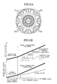
- Fig. 6A is an end view of flame stabilizers;
- Fig. 6B is a diagram showing the relation of amounts of flows;
- Fig. 7 is a partially enlarged sectional view of a premixer according to the present invention;
- Fig. 8 is a partially enlarged sectional view of another premixer according to the present invention;
- Fig. 9 is a partially enlarged sectional view of another premixer according to the present invention;
- Fig. 10 is a sectional view of another combustor according to the present invention;
- Fig. 11 is a sectional view of another combustor according to the present invention;
- Fig. 12 is a sectional view of another combustor according to the present invention;
- Fig. 13 is a diagram indicating the inclination angles of flame stabilizers relative to the combustor center axis and the degrees of influence of phenomena appearing depending on the inclination angle;
- Fig. 14 is an end view of flame stabilizers showing a case in which premixed fuel passages are not uniform in the circumferential direction; and
- Fig. 15 is an end view of flame stabilizers showing a case in which the premixed fuel passages are provided with rotating components centered on the combustor axis center.
-
- The schematic configuration of a gas turbine combustor according to a first embodiment of the present invention is illustrated in Figs. 1 through 3. As shown in Fig. 1, the combustor is surrounded by an
outer casing 1 and anend flange 2, and comprises acombustion chamber 4 surrounded by aliner 3, adiffusion swirl burner 5 which makes diffusion combustion, apremixer 6 which mixes fuel with air to create a premixture, across-fire tube 7 which propagates flame to the other combustor at the time of ignition, and a fuel and air supply systems. - The
diffusion swirl burner 5 disposed on the central axis of the combustor circulatesdiffusion combustion air 12b distributed fromcombustion air 12a with a swirl blade orswirler 8. Further, thediffusion swirl burner 5 mixes the air withgas 13a or fuel ejected from aliquid fuel nozzle 14 in thecombustion chamber 4, forming a diffuse flame. A plurality of swirlcombustion air nozzles 26 for supplyingdiffusion combustion air 12b into thecombustion chamber 4 is provided on the surrounding of thediffusion swirl burner 5. An atomizingair nozzle 27 is provided on the surrounding of liquid fuel nozzle 14a. Liquid fuel for diffusion combustion is atomized by a jet stream of atomizing air supplied from the atomizingair nozzle 27. The air inlet of theswirler 8 is provided withwater injection nozzles 29. Through these nozzles, water is mixed with thediffusion combustion air 12b so as to supplysteam 30 into the combustion chamber. - The
annular premixer 6 provided on the surrounding of thediffusion swirl burner 5 preliminarily mixes fuel ejected fromgas 13a which is injected out from a plurality ofpremixing fuel nozzles 9 with air forpremixing 12c distributed fromcombustion air 12a so as to create apremixture 11.Flame stabilizers 10 are provided in the entrance of thecombustion chamber 4 located downstream of thispremixture 11. Theflame stabilizers 10 form premixedflame 18 to stabilize flame. The plurality offlame stabilizers 10 are disposed radially relative to the central axis of the combustor. Further, each of theflame stabilizers 10 is provided slantly relative to the central axis of the combustor. Thepremixer 6 is provided withpartitions 22 so as to circumferentially divide the passage of thepremixer 6 from the entrance of the premixer to the upstream of theflame stabilizers 10. - The
flame stabilizers 10 disposed slantly relative to the combustor center axis may, as viewed from the side of the combustor, not only be in a near plane but also be in a slight convex or concave. - Fig. 2 is a transverse sectional view of two combustors of Fig. 1 coupled through the
cross-fire tube 7. Eightflame stabilizers 10 are provided for each combustor. Each of theflame stabilizers 10 is disposed between and upstream of thepartitions 22 of thepremixer 6 and between and upstream of the fuel nozzles for premixing. Each end of thecross-fire tube 7 is connected to theliner 3 in a radial direction relative to one of theflame stabilizers 10 disposed in the combustor, thereby connecting twocombustion chambers 4. - Fig. 3 is an enlarged sectional view of the diffusion swirl burner of the combustor indicated in Fig. 1. The function of each part and the flowing direction of fluid passing through each part are described hereunder.
Diffusion combustion air 12b of the diffusion swirl burner is changed to a swirling flow of air by theswirler 8. Further, the air flows into the combustion chamber with a certain inward directional angle directed to the combustor center axis. Liquid fuel ejected from the liquid fuel nozzle is atomized by atomizing air. Since this atomized liquid fuel is rapidly mixed with the swirling flow of air, occurrence of soot caused by combustion with an insufficient air is prevented and stable diffuse flame can be formed. Thewater injection nozzles 29 provided upstream of theswirler 8 inject water toward theswirler 8 causingdiffusion combustion air 12b to be mixed with water. Further, thereafter, water is rapidly mixed with liquid fuel in thecombustion chamber 4, so that heating density of fuel can be efficiently lowered and NOx can be reduced. The gas fuel nozzles provided near the air outlet of theswirler 8spout gas fuel 15b with a certain outward directional angle relative to the combustor center axis. When a flow of the spouted out gas fuel is small (when a load of the gas turbine is low), the velocity of flow of gas fuel is slow and penetrating force againstdiffusion combustion air 12b is small. For this reason, gas fuel fordiffusion combustion 15b is mixed mainly withdiffusion combustion air 12b to burn in the vicinity of the combustor center axis, allowing stable combustion. When a gas turbine load rises and gas fuel fordiffusion combustion 15b increases, penetration force of gas fuel increases and it is mixed with air (premixture) flowing in from the swirlcombustion air nozzles 26 andpremixer 6, so that an NOx reduction due to lean combustion can be attained. The swirlcombustion air nozzles 26 are disposed on the surrounding of the diffusion combustion burner so thatdiffusion combustion air 12b is allowed to flow into the combustion chamber in the same swirling direction as theswirler 8. This arrangement is to increase swirl flow in the vicinity of the combustor center axis and to stabilize flame. At the same time, the swirl flow expands air toward thepremixer 6, preventing sticking of diffuse flame to the face, of theflame stabilizers 10, in contact with thecombustion chamber 4 and a temperature rise of theflame stabilizers 10. Aslit 28 is provided on the periphery of the swirlcombustion air nozzles 26, so that diffusion combustion air is formed in a film state, and is allowed to flow out to the face, of theflame stabilizers 10, in contact with thecombustion chamber 4. With this configuration, a temperature rise of theflame stabilizers 10 is further prevented. Theflame stabilizers 10 disposed slantly relative to the combustor center axis make the passage of theannular premixer 6 narrow in the circumferential direction, and at the same time, wide in the inclined direction. Therefore, an increase in pressure loss at thepremixer 6 is suppressed, and at the same time, the air forpremixing 12c orpremixture 11 is ejected from thepremixer 6 in the direction of the combustor center axis of thecombustion chambers 4. - The
flame stabilizers 10 are slantly disposed so that its outer circumferential side is positioned on the downstream side relative to its inner circumferential side at the edge on the downstream side, and desirably, the inclination angle relative to the combustor center axis is set to 30° or more and 60° or less. With this configuration, after passing through the edge downstream of the flame stabilizers, the premixed combustion gas on the outer circumferential side deflects in the direction in which the premixed combustion gas converges to the axis center of the combustor, causing the diffusion combustion gas on the inner circumferential side to be diluted and mixed sufficiently. As a result, extension of the diffusion flame is prevented, reducing production of NOx, and occurrence of combustion temperature variations at the combustor exit is prevented, protecting turbine blades from being damaged. - The reason why the inclination angle of the
flame stabilizers 10 is set to 30° or more and 60° or less is explained. As shown in Fig. 13, as the inclination angle offlame stabilizers 10 relative to the combustor center axis reduces, the amplitude α of oscillatory combustion increases in the manner of an exponential function. When the inclination angle of theflame stabilizers 10 reduces, premixed combustion gas converges to the combustor center axis, causing high temperature diffusion combustion gas to be diluted. This further causes stability of flame to drop down and amplitude of oscillatory combustion to be increase. In particular, when an inclination angle reduces below 30°, amplitude of oscillatory combustion remarkably increases. A deviation of temperature β at the exit of the combustor increases in the manner of an exponential function as the inclination angle of theflame stabilizers 10 relative to the combustor center axis increases. Since the inclination angle of the flame stabilizers is large, an amount of displacement toward the direction in which the premixed combustion gas converges to the combustor axis center is small. For this reason, premixed combustion gas goes through thecombustion chamber 4 approximately directly. Thus, diffusion combustion gas on the inner circumferential side is not sufficiently mixed with premixed combustion gas. Then, temperature distribution at the exit of the combustor is put out of balance, causing damage to the turbine blades in the downstream. In particular, when the inclination angle exceeds 60°, the temperature distribution at the exit of the combustor remarkably deviates. Thus, when both the influences of amplitude of oscillatory combustion and temperature deviation at the exit of the combustor are taken into considerations, it is desirable to set the inclination angle to 30° or more and 60° or less. - Next, a description will be made of the operating principle of a combustor provided with flame stabilizers disposed radially at the exit of a premixed combustion burner in a premixed type gas turbine combustor comprising a pilot burner, a premixed combustion burner disposed on the periphery of the pilot burner, and a combustor liner in an approximately cylindrical shape which defines a combustion chamber in the combustor liner. In the case of an annular premixed combustion burner without flame stabilizers disposed at the exit of the premixed combustion burner, premixed combustion gas flows into the
combustion chamber 4 with the annular form thereof kept as is. This causes the flow of premixed combustion gas to cover up diffusion combustion gas spouted out from the pilot burner. The flow of the premixed combustion gas does not intend to actively put the flow of the diffusion combustion gas into disorder. Therefore, it is difficult to uniformly stir the premixed combustion gas with the diffusion combustion gas. Accordingly, the fuel is unevenly distributed, causing NOx to be produced. In contrast to this, flame stabilizers radially disposed at the exit of the premixed combustion burner are provided in the present embodiment. With these flame stabilizers, gas flowing out from the premixed combustion burner flows some portions and does not flow the other portions in the circumferential direction, which causes a distribution in which differences in the velocity of flow of fluid are alternately lined up in the circumferential direction. With the distribution like this, when gas fuel is used, premixed flame is stabilized, and when liquid fuel is used, mixing of air ejected from the premixed burner with the fuel of the pilot burner is promoted, preventing extension of diffusion flame. Since the temperature distribution at the exit of the combustor is uniformed, the turbine itself is protected, also. Further, a face of theflame stabilizers 10 that is in contact with thecombustion chamber 4 is inclined toward the combustor center axis. With this arrangement, premixed combustion gas flowing out from the premixed combustion burner is deflected toward the direction in which the premixed combustion gas converges actively to the combustor axis center. Then, premixed combustion gas is crossed with the diffusion combustion gas flowing out from the pilot burner. Thus mixing of gas is promoted, and production of NOx is reduced by preventing extension of diffusion flame. Further, occurrence of combustion temperature deviation at the exit of the combustor is prevented, and the turbine blades are protected from being damaged. Theflame stabilizers 10 radially disposed at the exit of the premixed combustion burner and the face of the flame stabilizers that are in contact with thecombustion chamber 4 are inclined relative to the combustor center axis. With the multiplier effects of these inclinations, stability of flame can be further improved. Further, the passages of the premixed gas extending from the face offlame stabilizers 10 that is in contact with thecombustion chamber 4 are not always needed to be spaced equally in the circumferential direction. As shown in Fig. 14, even if the passages ofpremixed fuel 11 are spaced unequally, diffusion combustion gas spouted out from the pilot burner can be effectively diluted and mixed. Furthermore, as shown in Fig. 15, the passages of the premixedfuel 11 may be provided with rotating components centered on the axial center of the combustor. Providing the rotating components like this, additional effects to stir diffusion combustion gas and premixed combustion gas can be expected. Further, the purposes of the arrangement wherein the radially disposedflame stabilizers 10 inclined relative to the combustor center axis are provided at the exit of the premixed combustion burner are to prevent the premixed combustion gas from flowing into thecombustion chamber 4 with the annular form thereof kept as is and to displace the premixed combustion gas to the diffusion combustion burner side. These purposes may be accomplished, for example, without providing flame stabilizers. To be more specific, annular premixed combustion burners disposed on the periphery of a pilot burner are divided in the circumferential direction with partitions, and the exit of the premixed combustion burner is faced to the side of the pilot burner. Then, premixed combustion gas flowing out from the premixed combustion burner is distributed so that strength of currents is lined up alternately in the circumferential direction, and the passage is displaced to the diffusion combustion burner side. Thus, it is possible to make the same premixed fuel passage as that when the radially disposedflame stabilizers 10 are provided. However, by forming flame stabilizers as described in the present embodiment, the purposes to prevent the premixed combustion gas from flowing into thecombustion chamber 4 with the annular form thereof kept as is and to displace the premixed combustion gas to the side of the diffusion combustion burner can be accomplished by a simple construction. - Further, the
flame stabilizers 10 are hold in a cantilever manner on the inner circumferential side. In other words, theflame stabilizers 10 are supported by (fixed to) the premixed combustion burner on the inner circumferential side, and the edges on the outer circumferential side of theflame stabilizers 10 are separate from the premixed combustion burner outer circumferential wall. With this configuration, stress caused by thermal expansion of theflame stabilizers 10 and the like can be released. Further, with this configuration, premixture 11 or air ejected into the combustion chamber through the space between the edge on the downstream side of theflame stabilizers 10 and premixed combustion burner outer circumferential wall prevents a temperature rise of combustion chamber side wall due to diffusion flame. - In regard to the combustor shown in Figs. 1, 2, and 3, examples of operating conditions and flame shapes at the time of gas fuel combustion and liquid fuel combustion are indicated in Figs. 4 and 5.
- Fig. 4 indicates a combustion state at the time of combustor ignition. The shape of flame at the time of gas fuel combustion is indicated on the upper side of the combustor center axis. The shape of flame at the time of liquid fuel combustion is indicated on the lower side of the combustor center axis. First of all, in one of the combustors,
gas 15a orliquid fuel 16a is supplied to thediffusion swirl burner 5, and an ignition device is used to form diffuseflame 19. Thegas 15a forms diffuseflame 19 after being mixed withdiffusion combustion air 12b. Flame of thegas 15a is stabilized by thediffusion swirl burner 5. Further, the downstream of theflame stabilizers 10 is in a low velocity swirl flow region. For this reason, the diffuseflame 19 expands radially along each of theflame stabilizers 10. Thecross-fire tube 7 is disposed on the outer circumference of theflame stabilizers 10, so that a high temperature combustion gas 20 is allowed to flow into thecross-fire tube 7 through theflame stabilizers 10 without being diluted by the air forpremixing 12c, allowing the adjacent combustor to be ignited. Further, in a case of using gas fuel, another combustor is ignited by thecross-fire tube 7, premixingfuel 15b is supplied in addition to thegas 15a, andpremixed flame 18 is also formed, whereby flame propagating performance can be enhanced. - After igniting the combustors, an amount of fuel supply is increased, and the gas turbine performs a speedup operation and a load operation. Fig. 5 shows flame shapes at the time of gas fuel combustion and liquid fuel combustion during the gas turbine operations respectively on the upper and lower sides of the combustor center axis. At the time of high load combustion with gas fuel, in order to attain diffusion combustion for stabilization of combustion and reduce NOx, premixing fuel is used to cause lean premixed combustion. The
flame stabilizers 10 are arranged radially, and further, inclined toward the direction of the combustor center axis. With these flame stabilizers, diffuseflame 19 spreads radially in the radial direction of the combustor along theflame stabilizers 10, andpremixing flame 18 grows in the direction of the combustor center axis. Thus, high temperature diffuseflame 19 and low temperature premixedflame 18 made by lean combustion cross each other in the circumferential direction of the combustor, thereby making momentary temperature at the combustor head uniform. The uniformity of momentary temperature at the combustor head promotes reduction of NOx and stabilization of combustion. - When liquid fuel is used, the diffuse
flame 19 spreads radially along theflame stabilizers 10 as aforementioned. Further, with theinclined flame stabilizers 10, the air forpremixing 12c flows out toward the combustor center axis, in other words, toward the downstream of thediffusion swirl burner 5. Then, mixing of the air forpremixing 12c and combustion gas made by the diffuseflame 19 is promoted downstream of thecombustion chambers 4, temperature deviation at the combustor exit is suppressed, whereby seizure of turbine blades can be prevented. Further, the diluting effect by the air forpremixing 12c can prevent the long flame of the diffuseflame 19. As a result, a high temperature combustion region reduces, allowing reduction of the amount of NOx emission. - Further, since the space is defined between the
flame stabilizers 10 and the outer circumferential wall of thepremixer 6, and high velocity air or premixture spouts out along the combustion chamber wall surface, the combustion chamber wall surface is cooled down and a rise in temperature is prevented under all combustion states. - Fig. 6 indicates an example of fuel and water flow control during the period from the ignition of the combustor to the rated load operation. As shown in Fig. 6A, the premixed fuel nozzles are divided into four sections (F1 through F4). With this construction, premixing gas fuel can be controlled by respective separate systems.
- Fig. 6B indicates fuel flows for gas turbine loads at the time of gas fuel combustion and liquid fuel combustion. In the case of gas fuel combustion, the gas turbine combustor is operated with diffuse fuel during the period from ignition of the combustor to a certain partial load through the increased speed of the gas turbine. Thereafter, premixed fuel is charged sequentially from F1 up to F4 in response to load rising. By charging the premixing fuel in this stepping manner, the premixing fuel can be controlled with its mixing ratio of fuel to air kept at the optimum level, allowing control of the premixed combustion to prevent unstable combustion and flashback.
- Further, at the time of liquid fuel combustion, the gas turbine combustor is operated by diffusion fuel only. However, water is charged at the time of a certain partial load in which combustion is stabilized, thereby intending to reduce the concentration of NOx.
- In the embodiment shown in Figs. 1 to 3, the present invention is applied to other constructions of
premixers 6 illustrated in Figs. 7, 8, and 9, respectively. - Fig. 7 indicates a case in which
partition 22 is disposed to extend from theflame stabilizers 10 to the downstream portion. Thispartition 22 circumferentially restrains the flow of a premixture from spaces amongflame stabilizers 10 toward the downstream. With this design, the circulation flow formed at the face, of theflame stabilizers 10, in contact with thecombustion chamber 4 can be stabilized, preventing unstable combustion and vibration combustion of the premixture. - In addition, NOx can be reduced and flashback can be prevented by reducing current deviation and fuel concentration deviation at the exit of the premixed combustion burner.
- Fig. 8 indicates a construction in which a
slit 28 and a plurality of cooling holes 31 are provided on the inner circumferential side of theflame stabilizer 10. The cooling holes 31 provided in theslit 28 spout film-like air branched out fromdiffusion combustion air 12b from the vicinity of the flame stabilizers toward the face, of theflame stabilizers 10, in contact with thecombustion chamber 4. With this construction, a rise in the temperature of theflame stabilizer 10 can be securely prevented. Further, theflame stabilizer 10 can be directly cooled down by providing theflame stabilizer 10 with the cooling holes at a portion extending from the inside of thepremixer 6 toward the downstream of theflame stabilizer 10. At the same time, the premixture ejected from the face, of theflame stabilizers 10, in contact with thecombustion chamber 4 through the cooling holes can make jet stream flame, improving stability of premixing flame. - Fig. 9 indicates a construction of the edge of the inner wall of the
premixer 6 between theflame stabilizers 10. In this construction, the edge has such an inclined surface as to enlarge the cross-sectional area of a passage for air orpremixture 11 of the premixed combustion burner from the upstream part toward the downstream part. With this construction, in the combustion chamber, the premixture or air for premixing becomes easy to flow in toward the combustor center axis, thereby improving mixing performance with diffuse fuel and reducing NOx. - Another embodiment according to the present invention having a construction shown in Fig. 10 is described referring to the combustor shown in Figs. 1 to 3. In this construction, a passage is made between the
premixer 6 and diffusion swirl burner so as to supplyauxiliary fuel 23 therethrough. In addition, a plurality ofauxiliary fuel nozzles 24 are provide in such a manner that fuel can be injected directly to thecombustion chamber 4 from between theflame stabilizers 10 and swirlcombustion air nozzles 26. At the time of gas fuel combustion, particularly at the time of partial load operation of the gas turbine, carry-over of premixed flame from diffuse flame may not be made well, causing unburned fuel to be ejected. In such a case, gas fuel is injected into the combustion chamber from theauxiliary fuel nozzles 24 disposed in the vicinity of theflame stabilizers 10. Then, the concentration of fuel on the inner circumferential side of thepremixture 11 increases, allowingpremixture 11 to be combusted completely. Further, if the diffuse gas fuel is reduced so as to decrease NOx, the diffuse flame becomes unstable. Together with the unstable diffuse flame, premixing flame may sway, causing a large oscillatory combustion to occur. In such a case, the diffuse flame can be dispersed by charging theauxiliary fuel 23, enabling the oscillatory combustion to be suppressed. - A combustor according to another embodiment of the present invention will be described with reference to Fig. 11, which is a longitudinal sectional view. Similarly to the embodiment of Fig. 10, a passage through which
auxiliary fuel 23 can be supplied is provided. Thepremixer 6 is located at the upstream portion between theflame stabilizers 10 close to the exit of the premixer. The inner periphery wall of thepremixer 6 is provided withauxiliary fuel nozzles 24 through which fuel can be injected into thepremixer 6. The fuel ejected from theauxiliary fuel nozzles 24 is mixed withpremixture 11 or air for premixing, and the mixed fuel is supplied into thecombustion chamber 4 through between theflame stabilizers 10. The effect is similar to that of the embodiment of Fig. 10. However, sinceauxiliary fuel 23 is mixed partially with thepremixture 11 or air for premixing, NOx can be further reduced. - Further, at the time of gas fuel combustion, carry-over of diffusion flame and premixed flame is secured by supplying
auxiliary fuel 23. At the same time, oscillatory combustion is reduced by dispersing fuel supplying positions in the radial direction of the combustion chamber radius. - Another embodiment of the present invention is described referring to Fig. 12 in relation to the combustor of Figs. 10 and 11. Fig. 12 shows an
auxiliary premixer 32 provided between thepremixer 6 anddiffusion swirl burner 5. The oscillatory combustion suppressing effect and reduction of unburned fuel at the time of partial loads are similar to those of the combustors of Figs. 10 and 11. However, since radial type flame stabilizers 10' are provided also at the exit of theauxiliary premixer 32, the premixing flame made by theauxiliary fuel 23 is stabilized. Further, since the diffusion flame can pass through the face, of the flame stabilizers 10', in contact with thecombustion chamber 4 of theauxiliary premixer 32, NOx can be further reduced without impairing flame propagating performance toward the adjacent furnace at the time of ignition and uniform temperature characteristics at the exit of the combustor. - Next, a description will below be made of a method of remodeling an already existing gas turbine combustor provided with a pilot burner and a premixed combustion burner disposed on the periphery of the pilot burner by providing flame stabilizers. When providing the radially disposed flame stabilizers on an already existing gas turbine combustor equipped with a pilot burner and a premixed combustion burner disposed on the periphery of the pilot burner, the flame stabilizers must be slanted so that the outer circumferential side thereof is positioned on the downstream side thereof relative to the inner circumferential side at edges on the downstream side. Further, desirably, the inclination angle relative to the combustor center axis must be 30° or more and 60° or less. With this construction, a premixed combustion gas on the outer circumferential side deflects in the direction in which the premixed combustion gas converges to the axial center of the combustor after passing through the edge on the front side of the flame stabilizers, causing diffusion combustion gas on the inner circumferential side to be diluted and mixed sufficiently. As a result, extension of diffusion flame is prevented to reduce the production of NOx, and occurrence of combustion temperature deviation at the exit of the combustor is prevented, protecting damage to turbine blades. Next, when providing radially disposed flame stabilizers, the inner circumference of the flame stabilizers is fixed in a cantilever manner. In other words, the flame stabilizers are supported (fixed) on the premixed combustion burner on the inner circumference side of the
flame stabilizers 10, and the edges on the outer circumferential side of theflame stabilizers 10 is separated from the outer circumferential wall of the premixed combustion burner. With this construction, stress caused by the thermal expansion and the like of theflame stabilizers 10 can be released. Further, with this construction,premixed fuel 11 or air ejected into the combustion chamber through the space between the edge on the downstream side of theflame stabilizers 10 and the outer circumferential wall of the premixed combustion burner prevents a rise in the temperature of combustion chamber sidewall due to diffusion flame. As described above, in a gas turbine of such a type as that the already installed combustor is equipped with a pilot burner and a premixed combustion burner disposed on the outer circumference of the pilot burner, the already existing combustor is not replaced of a new combustor produced by providing the radially disposedflame stabilizers 10 thereto but the already existing combustor is remodeled by providing the radially disposedflame combustors 10 thereto, whereby approximately equivalent performance can be displayed and production cost can be reduced. - As described above, combustion forms adaptable to gas and liquid fuel can be realized by applying the present invention to gas turbine combustors, and both stabilization of fuel and reduction of NOx can be compatible. Further, mixing of fuel with air is promoted at a combustion field, causing the temperature of fuel gas at the entrance of the gas turbine to be uniformed, and damage to turbine blades can be prevented. Furthermore, when a gas turbine system comprises multiple combustors and cross-fire tubes are used to ignite the individual combustors, the present invention improves the flame propagating performance, enabling a range of ignition to expand.
- Further, also in the case of an already existing gas turbine combustor equipped with a pilot burner and a premixed combustion burner disposed on the outer circumference of the pilot burner, the same effect as that of a gas turbine combustor equipped with radially disposed flame stabilizers from the beginning can be expected by providing the radially disposed flame stabilizers at the exit of the premixed combustion burner.
- According to the present invention, there are provided a gas turbine combustor that provides adequate combustion using combustors capable of using gas fuel and liquid fuel, and low-NOx performance, as well as a combustion method of the gas turbine combustor and a method of remodeling a gas turbine combustor.
- While the invention has been described in its preferred embodiments, it is to be understood that the words which have been used are words of description rather than limitation and that changes within the purview of the appended claims may be made without departing from the true scope and spirit of the invention in its broader aspects.
Claims (12)
- A gas turbine combustor comprising:wherein the pilot burner is provided with a fuel injection means which ejects at least one of gas fuel (15) and liquid fuel (16), anda pilot burner;a premixed combustion burner disposed on the circumference of said pilot burner;a liner (3) in an approximately cylindrical shape which is disposed on the downstream side of said premixed combustion burner, and which defines a combustion chamber (4) in the liner (3); andflame stabilizers (10) radially disposed at the exit of said premixed combustion burner;
a plurality of air nozzles (26) for injecting air into the combustion chamber (4) are located on the outside of said pilot burner and the inside of said premixed combustion chamber. - The gas turbine combustor according to claim 1, further comprising a cross-fire tube (7) provided with an opening which is disposed at the side wall of said liner (3) and which is circumferentially aligned with one of said flame stabilizers (10).
- The gas turbine combustor according to claim 1, wherein said flame stabilizers (10) are each inclined so that the outer circumferential side thereof is positioned on the downstream side relative to the inner circumferential side thereof at the edge thereof on the downstream side, and the inclination angle of the flame stabilizer (10) is 30° or more and 60° or less relative to the center axis of the combustor.
- The gas turbine combustor according to claim 1, wherein the inner circumferential sides of said flame stabilizers (10) are fixed to said premixed combustion burner, and edges, on the outer periphery side, of said flame stabilizers (10) are separated from the outer circumferential wall of said premixed combustion burner.
- The gas turbine combustor according to claim 1, wherein said air nozzle (27) is configured in such a manner as to spout out air swirlingly.
- The gas turbine combustor according to claim 1, wherein a slit (28) is provided outside said air nozzle (27) and inside said premixed combustion burner, and a means of allowing air to flow toward the flame stabilizer (10) is provided in said slit (28).
- The gas turbine combustor according to claim 1, wherein an air inlet portion or an air outlet portion of said pilot burner is provided with a nozzle (29) capable of ejecting water or steam.
- The gas turbine combustor according to claim 1, further comprising a partition (22) which divides a passage of said premixed combustion burner in the circumferential direction.
- A gas turbine combustor comprising:wherein said flame stabilizers (10) are slantly disposed so that the outer circumferential side thereof is positioned on the downstream side thereof relative to the inner circumferential side at the edge, on the downstream side, of the flame stabilizer (10), said flame stabilizers (10) are fixed to said premixed combustion burner on the inner circumferential side, and edges, on the outer circumferential side, of said flame stabilizers (10) are separated from the outer circumferential wall of said premixed combustion burner.a pilot burner which is provided with a fuel injection means capable of injecting gas fuel (15) and liquid fuel (16) ;a premixed combustion burner disposed in the outer circumference of said pilot burner;a liner (3) in an approximately cylindrical shape which is disposed on the downstream side of said premixed combustion burner, and which defines a combustion chamber (4) in the inner wall; andflame stabilizers (10) radially disposed at the exit of said premixed combustion burner;
- A combustion method of a gas turbine combustor including a pilot burner, a premixed combustion burner disposed on the outer circumference of said pilot burner, and a liner (3) in an approximately cylindrical shape which is disposed on the downstream side of said premixed combustion burner, and which defines a combustion chamber (4) in the inner wall, comprising the steps of:disposing flame stabilizers (10) radially at the exit of said premixed combustion burner;injecting at least one of gas fuel (15) and liquid fuel (16) from said pilot burner; andspouting out air into the combustion chamber (4) from a plurality of air nozzles (26) disposed outside said pilot burner and inside said premixed combustion burner.
- A method of remodeling a gas turbine combustor comprising: a pilot burner which is provided with a fuel injection means capable of injecting gas fuel (15) and liquid fuel (16); a premixed combustion burner disposed within a premixed fuel passage on the outer circumference of said pilot burner; and a combustor liner (3) in an approximately cylindrical shape which is disposed on the downstream side of said premixed combustion burner, and which defines a combustion chamber (4) therein;
said method characterized in that
flame stabilizers (10) are radially disposed at the exit of said premixed combustion burner,
said flame stabilizers are slantly disposed so that the outer circumferential side thereof is positioned on the downstream side thereof relative to the inner circumferential side, and edges on the outer circumferential side of said flame stabilizers and outer circumferential wall of said premixed combustion burner are disposed so as to define a space between said edges and said outer circumferential wall. - A premixed type gas turbine combustor comprising:wherein said annular premixed passage facing said combustion chamber (4) is configured such that, firstly, fluids in said premixed fuel passage are different from one another in the velocity of flow of fluid at the exit of the premixed fuel passage, secondary, the fluids are directed toward the center side of the combustor, and thirdly, the fluids intersect fuel spouted out from said pilot burner.a pilot burner;a premixed fuel passage disposed on the outer circumference of said pilot burner; anda combustor liner (3) in an approximately cylindrical shape which is disposed on the downstream side of said premixed fuel passage, and which defines a combustion chamber (4) therein;
Applications Claiming Priority (2)
| Application Number | Priority Date | Filing Date | Title |
|---|---|---|---|
| JP2002241291 | 2002-08-22 | ||
| JP2002241291 | 2002-08-22 |
Publications (3)
| Publication Number | Publication Date |
|---|---|
| EP1391657A2 true EP1391657A2 (en) | 2004-02-25 |
| EP1391657A3 EP1391657A3 (en) | 2005-04-27 |
| EP1391657B1 EP1391657B1 (en) | 2016-05-11 |
Family
ID=31185207
Family Applications (1)
| Application Number | Title | Priority Date | Filing Date |
|---|---|---|---|
| EP03005446.4A Expired - Lifetime EP1391657B1 (en) | 2002-08-22 | 2003-03-14 | Gas turbine combustor, combustion method of the gas turbine combustor, and method of remodeling a gas turbine combustor |
Country Status (2)
| Country | Link |
|---|---|
| US (1) | US7143583B2 (en) |
| EP (1) | EP1391657B1 (en) |
Cited By (12)
| Publication number | Priority date | Publication date | Assignee | Title |
|---|---|---|---|---|
| EP1591720A1 (en) * | 2004-04-30 | 2005-11-02 | United Technologies Corporation | Air assist fuel injector for a combustor |
| EP1736707A2 (en) * | 2005-06-24 | 2006-12-27 | Hitachi, Ltd. | Burner, gas turbine combustor, burner cooling method, and burner modifying method |
| GB2442331A (en) * | 2006-09-29 | 2008-04-02 | Gen Electric | An Injector for Injecting Fuel and Steam into a Gas Turbine Engine |
| EP2182287A2 (en) * | 2008-10-29 | 2010-05-05 | General Electric Company | Diluent Shroud for Combustor |
| CN102788369A (en) * | 2011-05-19 | 2012-11-21 | 通用电气公司 | Flexible combustor fuel nozzle |
| US8707671B2 (en) | 2008-10-01 | 2014-04-29 | Mitsubishi Heavy Industries, Ltd. | Fuel control method and fuel control apparatus for gas turbine and gas turbine |
| CN105318320A (en) * | 2015-10-30 | 2016-02-10 | 北京神雾环境能源科技集团股份有限公司 | Semi coke powder and lean gas mixing combustion device, system and method |
| EP3076077A4 (en) * | 2013-11-29 | 2017-07-12 | Mitsubishi Hitachi Power Systems, Ltd. | Nozzle, combustion apparatus, and gas turbine |
| EP2177834A3 (en) * | 2008-10-14 | 2017-08-16 | General Electric Company | Method and apparatus of introducing diluent flow into a combustor |
| CN108800205A (en) * | 2018-04-24 | 2018-11-13 | 南京航空航天大学 | A kind of eddy flow reinforcing/stamping combustion chamber |
| CN112283708A (en) * | 2020-11-16 | 2021-01-29 | 哈尔滨工业大学 | Multichannel air distribution adjusting rotary kiln humidifying low-nitrogen combustor |
| EP3896341A1 (en) * | 2020-04-15 | 2021-10-20 | Marvel-Tech Ltd | Gas turbine combustor |
Families Citing this family (81)
| Publication number | Priority date | Publication date | Assignee | Title |
|---|---|---|---|---|
| DE10049203A1 (en) * | 2000-10-05 | 2002-05-23 | Alstom Switzerland Ltd | Process for introducing fuel into a premix burner |
| DE10326720A1 (en) * | 2003-06-06 | 2004-12-23 | Rolls-Royce Deutschland Ltd & Co Kg | Burner for a gas turbine combustor |
| US7661269B2 (en) * | 2003-07-25 | 2010-02-16 | Ansaldo Energia S.P.A. | Gas turbine burner |
| GB2404729B (en) * | 2003-08-08 | 2008-01-23 | Rolls Royce Plc | Fuel injection |
| DE10353423B3 (en) * | 2003-11-15 | 2005-04-14 | Eads Space Transportation Gmbh | Rocket motor casing has cooling passages for fuel or liquid oxygen within concentric structure |
| US7086235B2 (en) * | 2003-11-26 | 2006-08-08 | United Technologies Corporation | Cascade ignition of catalytic combustors |
| KR100436601B1 (en) * | 2003-12-20 | 2004-06-18 | 학교법인 영남학원 | The multi-nozzle arrays for low NOx emission and high heating load combustor |
| US7093444B2 (en) * | 2003-12-20 | 2006-08-22 | Yeungnam Educational Foundation | Simultaneous combustion with premixed and non-premixed fuels and fuel injector for such combustion |
| ITMI20032621A1 (en) * | 2003-12-30 | 2005-06-30 | Nuovo Pignone Spa | COMBUSTION SYSTEM WITH LOW POLLUTING EMISSIONS |
| WO2005085709A1 (en) * | 2004-03-03 | 2005-09-15 | Mitsubishi Heavy Industries, Ltd. | Combustor |
| US7082765B2 (en) * | 2004-09-01 | 2006-08-01 | General Electric Company | Methods and apparatus for reducing gas turbine engine emissions |
| WO2006090466A1 (en) * | 2005-02-25 | 2006-08-31 | Ihi Corporation | Fuel injection valve, combustor using the fuel injection valve, and fuel injection method for the fuel injection valve |
| US8062027B2 (en) * | 2005-08-11 | 2011-11-22 | Elster Gmbh | Industrial burner and method for operating an industrial burner |
| US7536862B2 (en) * | 2005-09-01 | 2009-05-26 | General Electric Company | Fuel nozzle for gas turbine engines |
| US8881531B2 (en) * | 2005-12-14 | 2014-11-11 | Rolls-Royce Power Engineering Plc | Gas turbine engine premix injectors |
| FR2896031B1 (en) * | 2006-01-09 | 2008-04-18 | Snecma Sa | MULTIMODE INJECTION DEVICE FOR COMBUSTION CHAMBER, IN PARTICULAR A TURBOREACTOR |
| US20070204624A1 (en) * | 2006-03-01 | 2007-09-06 | Smith Kenneth O | Fuel injector for a turbine engine |
| US7810333B2 (en) * | 2006-10-02 | 2010-10-12 | General Electric Company | Method and apparatus for operating a turbine engine |
| US20080081301A1 (en) * | 2006-10-03 | 2008-04-03 | Hannum Mark C | Low NOx combustion |
| GB2454247A (en) * | 2007-11-02 | 2009-05-06 | Siemens Ag | A Combustor for a Gas-Turbine Engine Has a Burner Head with Fuel Delivered at a Compound Angle |
| EP2241808B1 (en) * | 2007-11-29 | 2016-02-17 | United Technologies Corporation | Method of operation a gas turbine engine |
| JP4959524B2 (en) | 2007-11-29 | 2012-06-27 | 三菱重工業株式会社 | Burning burner |
| JP2009156542A (en) * | 2007-12-27 | 2009-07-16 | Mitsubishi Heavy Ind Ltd | Burner for gas turbine |
| US8042339B2 (en) * | 2008-03-12 | 2011-10-25 | General Electric Company | Lean direct injection combustion system |
| GB0814791D0 (en) * | 2008-08-14 | 2008-09-17 | Rolls Royce Plc | Liquid ejector |
| US20100089020A1 (en) * | 2008-10-14 | 2010-04-15 | General Electric Company | Metering of diluent flow in combustor |
| US20100089022A1 (en) * | 2008-10-14 | 2010-04-15 | General Electric Company | Method and apparatus of fuel nozzle diluent introduction |
| US9121609B2 (en) | 2008-10-14 | 2015-09-01 | General Electric Company | Method and apparatus for introducing diluent flow into a combustor |
| US20100192582A1 (en) | 2009-02-04 | 2010-08-05 | Robert Bland | Combustor nozzle |
| EP2299091A1 (en) * | 2009-09-07 | 2011-03-23 | Alstom Technology Ltd | Method for Switching over a Gas Turbine Burner Operation from Liquid to Gas Fuel and Vice-Versa |
| US8584467B2 (en) * | 2010-02-12 | 2013-11-19 | General Electric Company | Method of controlling a combustor for a gas turbine |
| US8468834B2 (en) * | 2010-02-12 | 2013-06-25 | General Electric Company | Fuel injector nozzle |
| US8555648B2 (en) * | 2010-02-12 | 2013-10-15 | General Electric Company | Fuel injector nozzle |
| US9017064B2 (en) | 2010-06-08 | 2015-04-28 | Siemens Energy, Inc. | Utilizing a diluent to lower combustion instabilities in a gas turbine engine |
| JP5156066B2 (en) * | 2010-08-27 | 2013-03-06 | 株式会社日立製作所 | Gas turbine combustor |
| JP5546432B2 (en) * | 2010-11-30 | 2014-07-09 | 株式会社日立製作所 | Gas turbine combustor and fuel supply method |
| US8863525B2 (en) | 2011-01-03 | 2014-10-21 | General Electric Company | Combustor with fuel staggering for flame holding mitigation |
| US20120210717A1 (en) * | 2011-02-21 | 2012-08-23 | General Electric Company | Apparatus for injecting fluid into a combustion chamber of a combustor |
| US9068750B2 (en) * | 2011-03-04 | 2015-06-30 | General Electric Company | Combustor with a pre-nozzle mixing cap assembly |
| US8365534B2 (en) * | 2011-03-15 | 2013-02-05 | General Electric Company | Gas turbine combustor having a fuel nozzle for flame anchoring |
| US8826667B2 (en) | 2011-05-24 | 2014-09-09 | General Electric Company | System and method for flow control in gas turbine engine |
| US8997452B2 (en) * | 2011-10-20 | 2015-04-07 | General Electric Company | Systems and methods for regulating fuel and reactive fluid supply in turbine engines |
| US8943832B2 (en) * | 2011-10-26 | 2015-02-03 | General Electric Company | Fuel nozzle assembly for use in turbine engines and methods of assembling same |
| US20130152594A1 (en) * | 2011-12-15 | 2013-06-20 | Solar Turbines Inc. | Gas turbine and fuel injector for the same |
| US9217570B2 (en) * | 2012-01-20 | 2015-12-22 | General Electric Company | Axial flow fuel nozzle with a stepped center body |
| US20130219897A1 (en) * | 2012-02-28 | 2013-08-29 | Mitsubishi Heavy Industries, Ltd. | Combustor and gas turbine |
| JP5486619B2 (en) * | 2012-02-28 | 2014-05-07 | 株式会社日立製作所 | Gas turbine combustor and operation method thereof |
| US20130263605A1 (en) * | 2012-04-04 | 2013-10-10 | General Electric | Diffusion Combustor Fuel Nozzle |
| DE102012216080A1 (en) * | 2012-08-17 | 2014-02-20 | Dürr Systems GmbH | burner |
| JP5889754B2 (en) * | 2012-09-05 | 2016-03-22 | 三菱日立パワーシステムズ株式会社 | Gas turbine combustor |
| US9677766B2 (en) * | 2012-11-28 | 2017-06-13 | General Electric Company | Fuel nozzle for use in a turbine engine and method of assembly |
| US20140260302A1 (en) * | 2013-03-14 | 2014-09-18 | General Electric Company | DIFFUSION COMBUSTOR FUEL NOZZLE FOR LIMITING NOx EMISSIONS |
| ITMI20131816A1 (en) * | 2013-10-31 | 2015-05-01 | Ansaldo Energia Spa | INJECTOR WITH A DOUBLE NOZZLE SPEAR GAS TURBINE SYSTEM, GAS TURBINE SYSTEM AND A GAS TURBINE FEEDING METHOD |
| US9500367B2 (en) | 2013-11-11 | 2016-11-22 | General Electric Company | Combustion casing manifold for high pressure air delivery to a fuel nozzle pilot system |
| US20160348911A1 (en) * | 2013-12-12 | 2016-12-01 | Siemens Energy, Inc. | W501 d5/d5a df42 combustion system |
| JP6177187B2 (en) | 2014-04-30 | 2017-08-09 | 三菱日立パワーシステムズ株式会社 | Gas turbine combustor, gas turbine, control apparatus and control method |
| US10094565B2 (en) * | 2014-05-23 | 2018-10-09 | Mitsubishi Hitachi Power Systems, Ltd. | Gas turbine combustor and gas turbine |
| AU2015265278B2 (en) * | 2014-05-30 | 2018-04-05 | B&B Agema Gmbh | Combustor for gas turbine engine |
| US10161635B2 (en) * | 2014-06-13 | 2018-12-25 | Rolls-Royce Corporation | Combustor with spring-loaded crossover tubes |
| JP6325930B2 (en) * | 2014-07-24 | 2018-05-16 | 三菱日立パワーシステムズ株式会社 | Gas turbine combustor |
| US20160053681A1 (en) * | 2014-08-20 | 2016-02-25 | General Electric Company | Liquid fuel combustor having an oxygen-depleted gas (odg) injection system for a gas turbomachine |
| US10317083B2 (en) * | 2014-10-03 | 2019-06-11 | Pratt & Whitney Canada Corp. | Fuel nozzle |
| GB201511841D0 (en) * | 2015-07-07 | 2015-08-19 | Rolls Royce Plc | Fuel spray nozel for a gas turbine engine |
| RU2015156419A (en) | 2015-12-28 | 2017-07-04 | Дженерал Электрик Компани | The fuel injector assembly made with a flame stabilizer pre-mixed mixture |
| DE112017002620B4 (en) | 2016-05-23 | 2023-01-26 | Mitsubishi Heavy Industries, Ltd. | combustor and gas turbine |
| JP6779097B2 (en) * | 2016-10-24 | 2020-11-04 | 三菱パワー株式会社 | Gas turbine combustor and its operation method |
| EP3677839B1 (en) * | 2017-08-28 | 2023-05-03 | Kawasaki Jukogyo Kabushiki Kaisha | Fuel injector |
| CN107575864A (en) * | 2017-09-20 | 2018-01-12 | 上海岱鼎工业设备有限公司 | A kind of linear low nitrogen gas burner |
| KR102046457B1 (en) * | 2017-11-09 | 2019-11-19 | 두산중공업 주식회사 | Combustor and gas turbine including the same |
| CN107975822B (en) * | 2017-12-19 | 2023-03-14 | 中国科学院工程热物理研究所 | Combustion chamber of gas turbine and gas turbine using combustion chamber |
| CN108332234B (en) * | 2018-01-24 | 2019-12-20 | 中国航发湖南动力机械研究所 | Multi-fuel-adaptive combustion chamber and multi-stage fuel supply premixing and control method |
| KR102071324B1 (en) * | 2018-02-20 | 2020-01-30 | 두산중공업 주식회사 | Nozzle for combustor, combustor, and gas turbine including the same |
| US10941941B2 (en) * | 2018-07-05 | 2021-03-09 | Solar Turbines Incorporated | Fuel injector with a center body assembly |
| US11286884B2 (en) | 2018-12-12 | 2022-03-29 | General Electric Company | Combustion section and fuel injector assembly for a heat engine |
| US11073114B2 (en) | 2018-12-12 | 2021-07-27 | General Electric Company | Fuel injector assembly for a heat engine |
| US11156360B2 (en) * | 2019-02-18 | 2021-10-26 | General Electric Company | Fuel nozzle assembly |
| JP7257358B2 (en) * | 2020-05-01 | 2023-04-13 | 三菱重工業株式会社 | gas turbine combustor |
| US11958024B2 (en) * | 2020-10-15 | 2024-04-16 | Pruitt Production Services, Inc. | Flares for mixing and burning multiple gasses |
| KR102382634B1 (en) * | 2020-12-22 | 2022-04-01 | 두산중공업 주식회사 | Nozzle for combustor, combustor, and gas turbine including the same |
| EP4317787A1 (en) * | 2021-03-26 | 2024-02-07 | IHI Corporation | Combustion device and gas turbine system |
| CN114017773B (en) * | 2021-12-16 | 2022-04-22 | 东营市悦凯石油装备有限公司 | Novel anti-backfire gas mixer for gas generator set |
Citations (2)
| Publication number | Priority date | Publication date | Assignee | Title |
|---|---|---|---|---|
| JPH03255815A (en) | 1990-03-02 | 1991-11-14 | Hitachi Ltd | Low nox gas turbine combustor |
| JPH1194255A (en) | 1997-09-24 | 1999-04-09 | Mitsubishi Heavy Ind Ltd | Combustor for oil/gas-burning gas turbine |
Family Cites Families (16)
| Publication number | Priority date | Publication date | Assignee | Title |
|---|---|---|---|---|
| US2984979A (en) * | 1951-03-27 | 1961-05-23 | Eldon R Babcock | Vortex pilot flame source for ramjet engines |
| US2715813A (en) * | 1952-04-14 | 1955-08-23 | Frederick T Holmes | Fuel injector and flame holder |
| JPS59208131A (en) | 1983-05-12 | 1984-11-26 | Hitachi Ltd | Component for gas turbine combustor |
| JPH01114623A (en) * | 1987-10-27 | 1989-05-08 | Toshiba Corp | Gas turbine combustor |
| US5228283A (en) * | 1990-05-01 | 1993-07-20 | General Electric Company | Method of reducing nox emissions in a gas turbine engine |
| US5285632A (en) * | 1993-02-08 | 1994-02-15 | General Electric Company | Low NOx combustor |
| US5575153A (en) * | 1993-04-07 | 1996-11-19 | Hitachi, Ltd. | Stabilizer for gas turbine combustors and gas turbine combustor equipped with the stabilizer |
| FR2706588B1 (en) * | 1993-06-16 | 1995-07-21 | Snecma | Fuel injection system for combustion chamber. |
| JP2954480B2 (en) * | 1994-04-08 | 1999-09-27 | 株式会社日立製作所 | Gas turbine combustor |
| JP3346034B2 (en) * | 1994-06-30 | 2002-11-18 | 石川島播磨重工業株式会社 | Gas turbine combustion equipment |
| JP3183053B2 (en) * | 1994-07-20 | 2001-07-03 | 株式会社日立製作所 | Gas turbine combustor and gas turbine |
| US5836164A (en) * | 1995-01-30 | 1998-11-17 | Hitachi, Ltd. | Gas turbine combustor |
| US6038861A (en) * | 1998-06-10 | 2000-03-21 | Siemens Westinghouse Power Corporation | Main stage fuel mixer with premixing transition for dry low Nox (DLN) combustors |
| US6082111A (en) * | 1998-06-11 | 2000-07-04 | Siemens Westinghouse Power Corporation | Annular premix section for dry low-NOx combustors |
| DE69930455T2 (en) * | 1998-11-12 | 2006-11-23 | Mitsubishi Heavy Industries, Ltd. | Gas turbine combustor |
| JP4709433B2 (en) * | 2001-06-29 | 2011-06-22 | 三菱重工業株式会社 | Gas turbine combustor |
-
2003
- 2003-03-07 US US10/382,500 patent/US7143583B2/en not_active Expired - Lifetime
- 2003-03-14 EP EP03005446.4A patent/EP1391657B1/en not_active Expired - Lifetime
Patent Citations (2)
| Publication number | Priority date | Publication date | Assignee | Title |
|---|---|---|---|---|
| JPH03255815A (en) | 1990-03-02 | 1991-11-14 | Hitachi Ltd | Low nox gas turbine combustor |
| JPH1194255A (en) | 1997-09-24 | 1999-04-09 | Mitsubishi Heavy Ind Ltd | Combustor for oil/gas-burning gas turbine |
Cited By (23)
| Publication number | Priority date | Publication date | Assignee | Title |
|---|---|---|---|---|
| US7251940B2 (en) | 2004-04-30 | 2007-08-07 | United Technologies Corporation | Air assist fuel injector for a combustor |
| EP1591720A1 (en) * | 2004-04-30 | 2005-11-02 | United Technologies Corporation | Air assist fuel injector for a combustor |
| EP1736707A3 (en) * | 2005-06-24 | 2014-03-19 | Hitachi, Ltd. | Burner, gas turbine combustor, burner cooling method, and burner modifying method |
| EP1736707A2 (en) * | 2005-06-24 | 2006-12-27 | Hitachi, Ltd. | Burner, gas turbine combustor, burner cooling method, and burner modifying method |
| GB2442331A (en) * | 2006-09-29 | 2008-04-02 | Gen Electric | An Injector for Injecting Fuel and Steam into a Gas Turbine Engine |
| GB2442331B (en) * | 2006-09-29 | 2011-02-23 | Gen Electric | Methods and apparatus for injecting fluids into a turbine engine |
| US8707671B2 (en) | 2008-10-01 | 2014-04-29 | Mitsubishi Heavy Industries, Ltd. | Fuel control method and fuel control apparatus for gas turbine and gas turbine |
| US9631559B2 (en) | 2008-10-01 | 2017-04-25 | Mitsubishi Hitachi Power Systems, Ltd. | Fuel control method and fuel control apparatus for gas turbine and gas turbine |
| EP2177834A3 (en) * | 2008-10-14 | 2017-08-16 | General Electric Company | Method and apparatus of introducing diluent flow into a combustor |
| EP2182287A2 (en) * | 2008-10-29 | 2010-05-05 | General Electric Company | Diluent Shroud for Combustor |
| EP2182287A3 (en) * | 2008-10-29 | 2017-05-03 | General Electric Company | Diluent Shroud for Combustor |
| US8448442B2 (en) | 2011-05-19 | 2013-05-28 | General Electric Company | Flexible combustor fuel nozzle |
| CN102788369A (en) * | 2011-05-19 | 2012-11-21 | 通用电气公司 | Flexible combustor fuel nozzle |
| EP2525153A1 (en) * | 2011-05-19 | 2012-11-21 | General Electric Company | Flexible combustor fuel nozzle |
| US10570820B2 (en) | 2013-11-29 | 2020-02-25 | Mitsubishi Hitachi Power Systems, Ltd. | Nozzle, combustion apparatus, and gas turbine |
| EP3076077A4 (en) * | 2013-11-29 | 2017-07-12 | Mitsubishi Hitachi Power Systems, Ltd. | Nozzle, combustion apparatus, and gas turbine |
| CN105318320A (en) * | 2015-10-30 | 2016-02-10 | 北京神雾环境能源科技集团股份有限公司 | Semi coke powder and lean gas mixing combustion device, system and method |
| CN105318320B (en) * | 2015-10-30 | 2018-06-08 | 神雾科技集团股份有限公司 | A kind of semi-coke powder and poor gas mixed combustion apparatus, system and method |
| CN108800205A (en) * | 2018-04-24 | 2018-11-13 | 南京航空航天大学 | A kind of eddy flow reinforcing/stamping combustion chamber |
| CN108800205B (en) * | 2018-04-24 | 2020-04-24 | 南京航空航天大学 | Swirl afterburning/stamping combustion chamber |
| EP3896341A1 (en) * | 2020-04-15 | 2021-10-20 | Marvel-Tech Ltd | Gas turbine combustor |
| US11365885B2 (en) | 2020-04-15 | 2022-06-21 | Marvel-Tech Ltd. | Gas turbine combustor with fuel injector including a downstream guide member |
| CN112283708A (en) * | 2020-11-16 | 2021-01-29 | 哈尔滨工业大学 | Multichannel air distribution adjusting rotary kiln humidifying low-nitrogen combustor |
Also Published As
| Publication number | Publication date |
|---|---|
| EP1391657A3 (en) | 2005-04-27 |
| EP1391657B1 (en) | 2016-05-11 |
| US20040035114A1 (en) | 2004-02-26 |
| US7143583B2 (en) | 2006-12-05 |
Similar Documents
| Publication | Publication Date | Title |
|---|---|---|
| US7143583B2 (en) | Gas turbine combustor, combustion method of the gas turbine combustor, and method of remodeling a gas turbine combustor | |
| EP3141817B1 (en) | Gas turbine combustor | |
| EP1985926B1 (en) | Combustion equipment and combustion method | |
| JP4846271B2 (en) | Premix burner with impingement cooled centerbody and cooling method for centerbody | |
| EP2530382B1 (en) | Fuel injector | |
| JP3183053B2 (en) | Gas turbine combustor and gas turbine | |
| US6301899B1 (en) | Mixer having intervane fuel injection | |
| EP1543272B1 (en) | Turbine engine fuel nozzle | |
| JP2007033025A (en) | Gas turbine combustor, combustion method for gas turbine combustor, and method of modifying gas turbine combustor | |
| US20090056336A1 (en) | Gas turbine premixer with radially staged flow passages and method for mixing air and gas in a gas turbine | |
| EP0905443A2 (en) | Dual-fuel nozzle for inhibiting carbon deposition onto combustor surfaces in a gas turbine | |
| EP0728989B1 (en) | Gas turbine engine combustor | |
| US20090320484A1 (en) | Methods and systems to facilitate reducing flashback/flame holding in combustion systems | |
| EP1826485B1 (en) | Burner and method of combustion with the burner | |
| EP1389713A1 (en) | Premixed exit ring pilot burner | |
| JP5940227B2 (en) | Gas turbine combustor | |
| KR102165972B1 (en) | Burner assembly, combustor, and gas turbine | |
| JP3956882B2 (en) | Gas turbine combustor and gas turbine combustor remodeling method | |
| CN109642730B (en) | Burner with combined fuel and air supply in the wall of the burner | |
| US20160146464A1 (en) | Combustor with annular bluff body | |
| JP2009531642A (en) | Burner for heat generator operation | |
| JP3192055B2 (en) | Gas turbine combustor | |
| JP4066658B2 (en) | Gas turbine combustor, gas turbine combustor premixing device, and gas turbine combustor premixing method | |
| JP2007146697A (en) | Combustor and combustion air supply method of combustor | |
| JP3872960B2 (en) | Gas turbine combustor |
Legal Events
| Date | Code | Title | Description |
|---|---|---|---|
| PUAI | Public reference made under article 153(3) epc to a published international application that has entered the european phase |
Free format text: ORIGINAL CODE: 0009012 |
|
| AK | Designated contracting states |
Kind code of ref document: A2 Designated state(s): AT BE BG CH CY CZ DE DK EE ES FI FR GB GR HU IE IT LI LU MC NL PT RO SE SI SK TR |
|
| AX | Request for extension of the european patent |
Extension state: AL LT LV MK |
|
| PUAL | Search report despatched |
Free format text: ORIGINAL CODE: 0009013 |
|
| AK | Designated contracting states |
Kind code of ref document: A3 Designated state(s): AT BE BG CH CY CZ DE DK EE ES FI FR GB GR HU IE IT LI LU MC NL PT RO SE SI SK TR |
|
| AX | Request for extension of the european patent |
Extension state: AL LT LV MK |
|
| RIC1 | Information provided on ipc code assigned before grant |
Ipc: 7F 23R 3/48 B Ipc: 7F 23D 14/70 B Ipc: 7F 23R 3/28 A Ipc: 7F 23R 3/18 B |
|
| 17P | Request for examination filed |
Effective date: 20050818 |
|
| AKX | Designation fees paid |
Designated state(s): DE FR GB |
|
| 17Q | First examination report despatched |
Effective date: 20071213 |
|
| RAP1 | Party data changed (applicant data changed or rights of an application transferred) |
Owner name: MITSUBISHI HITACHI POWER SYSTEMS, LTD. |
|
| RAP1 | Party data changed (applicant data changed or rights of an application transferred) |
Owner name: MITSUBISHI HITACHI POWER SYSTEMS, LTD. |
|
| GRAP | Despatch of communication of intention to grant a patent |
Free format text: ORIGINAL CODE: EPIDOSNIGR1 |
|
| INTG | Intention to grant announced |
Effective date: 20150925 |
|
| GRAS | Grant fee paid |
Free format text: ORIGINAL CODE: EPIDOSNIGR3 |
|
| GRAA | (expected) grant |
Free format text: ORIGINAL CODE: 0009210 |
|
| AK | Designated contracting states |
Kind code of ref document: B1 Designated state(s): DE FR GB |
|
| REG | Reference to a national code |
Ref country code: GB Ref legal event code: FG4D |
|
| REG | Reference to a national code |
Ref country code: DE Ref legal event code: R096 Ref document number: 60348924 Country of ref document: DE |
|
| REG | Reference to a national code |
Ref country code: FR Ref legal event code: PLFP Year of fee payment: 15 |
|
| REG | Reference to a national code |
Ref country code: DE Ref legal event code: R097 Ref document number: 60348924 Country of ref document: DE |
|
| PLBE | No opposition filed within time limit |
Free format text: ORIGINAL CODE: 0009261 |
|
| STAA | Information on the status of an ep patent application or granted ep patent |
Free format text: STATUS: NO OPPOSITION FILED WITHIN TIME LIMIT |
|
| 26N | No opposition filed |
Effective date: 20170214 |
|
| REG | Reference to a national code |
Ref country code: FR Ref legal event code: PLFP Year of fee payment: 16 |
|
| PGFP | Annual fee paid to national office [announced via postgrant information from national office to epo] |
Ref country code: GB Payment date: 20220127 Year of fee payment: 20 Ref country code: DE Payment date: 20220203 Year of fee payment: 20 |
|
| PGFP | Annual fee paid to national office [announced via postgrant information from national office to epo] |
Ref country code: FR Payment date: 20220209 Year of fee payment: 20 |
|
| REG | Reference to a national code |
Ref country code: DE Ref legal event code: R071 Ref document number: 60348924 Country of ref document: DE |
|
| REG | Reference to a national code |
Ref country code: GB Ref legal event code: PE20 Expiry date: 20230313 |
|
| PG25 | Lapsed in a contracting state [announced via postgrant information from national office to epo] |
Ref country code: GB Free format text: LAPSE BECAUSE OF EXPIRATION OF PROTECTION Effective date: 20230313 |