EP2525152A2 - Injecteurs multipoints - Google Patents
Injecteurs multipoints Download PDFInfo
- Publication number
- EP2525152A2 EP2525152A2 EP12165814A EP12165814A EP2525152A2 EP 2525152 A2 EP2525152 A2 EP 2525152A2 EP 12165814 A EP12165814 A EP 12165814A EP 12165814 A EP12165814 A EP 12165814A EP 2525152 A2 EP2525152 A2 EP 2525152A2
- Authority
- EP
- European Patent Office
- Prior art keywords
- fuel
- air
- ring
- swirlers
- injector
- Prior art date
- Legal status (The legal status is an assumption and is not a legal conclusion. Google has not performed a legal analysis and makes no representation as to the accuracy of the status listed.)
- Granted
Links
Images


Classifications
-
- F—MECHANICAL ENGINEERING; LIGHTING; HEATING; WEAPONS; BLASTING
- F23—COMBUSTION APPARATUS; COMBUSTION PROCESSES
- F23R—GENERATING COMBUSTION PRODUCTS OF HIGH PRESSURE OR HIGH VELOCITY, e.g. GAS-TURBINE COMBUSTION CHAMBERS
- F23R3/00—Continuous combustion chambers using liquid or gaseous fuel
- F23R3/28—Continuous combustion chambers using liquid or gaseous fuel characterised by the fuel supply
- F23R3/283—Attaching or cooling of fuel injecting means including supports for fuel injectors, stems, or lances
-
- F—MECHANICAL ENGINEERING; LIGHTING; HEATING; WEAPONS; BLASTING
- F23—COMBUSTION APPARATUS; COMBUSTION PROCESSES
- F23D—BURNERS
- F23D11/00—Burners using a direct spraying action of liquid droplets or vaporised liquid into the combustion space
- F23D11/10—Burners using a direct spraying action of liquid droplets or vaporised liquid into the combustion space the spraying being induced by a gaseous medium, e.g. water vapour
- F23D11/101—Burners using a direct spraying action of liquid droplets or vaporised liquid into the combustion space the spraying being induced by a gaseous medium, e.g. water vapour medium and fuel meeting before the burner outlet
- F23D11/102—Burners using a direct spraying action of liquid droplets or vaporised liquid into the combustion space the spraying being induced by a gaseous medium, e.g. water vapour medium and fuel meeting before the burner outlet in an internal mixing chamber
- F23D11/103—Burners using a direct spraying action of liquid droplets or vaporised liquid into the combustion space the spraying being induced by a gaseous medium, e.g. water vapour medium and fuel meeting before the burner outlet in an internal mixing chamber with means creating a swirl inside the mixing chamber
-
- F—MECHANICAL ENGINEERING; LIGHTING; HEATING; WEAPONS; BLASTING
- F23—COMBUSTION APPARATUS; COMBUSTION PROCESSES
- F23D—BURNERS
- F23D11/00—Burners using a direct spraying action of liquid droplets or vaporised liquid into the combustion space
- F23D11/36—Details
- F23D11/38—Nozzles; Cleaning devices therefor
- F23D11/383—Nozzles; Cleaning devices therefor with swirl means
-
- F—MECHANICAL ENGINEERING; LIGHTING; HEATING; WEAPONS; BLASTING
- F23—COMBUSTION APPARATUS; COMBUSTION PROCESSES
- F23R—GENERATING COMBUSTION PRODUCTS OF HIGH PRESSURE OR HIGH VELOCITY, e.g. GAS-TURBINE COMBUSTION CHAMBERS
- F23R3/00—Continuous combustion chambers using liquid or gaseous fuel
- F23R3/02—Continuous combustion chambers using liquid or gaseous fuel characterised by the air-flow or gas-flow configuration
- F23R3/04—Air inlet arrangements
- F23R3/10—Air inlet arrangements for primary air
- F23R3/12—Air inlet arrangements for primary air inducing a vortex
-
- F—MECHANICAL ENGINEERING; LIGHTING; HEATING; WEAPONS; BLASTING
- F23—COMBUSTION APPARATUS; COMBUSTION PROCESSES
- F23R—GENERATING COMBUSTION PRODUCTS OF HIGH PRESSURE OR HIGH VELOCITY, e.g. GAS-TURBINE COMBUSTION CHAMBERS
- F23R3/00—Continuous combustion chambers using liquid or gaseous fuel
- F23R3/28—Continuous combustion chambers using liquid or gaseous fuel characterised by the fuel supply
- F23R3/34—Feeding into different combustion zones
- F23R3/346—Feeding into different combustion zones for staged combustion
Definitions
- the present invention relates to injectors and nozzles, and more particularly to injectors and nozzles for atomizing liquids.
- the drive for cleaner, quieter, and more efficient aircraft has created a demand to develop lean burn jet engines, where most of the combustion air enters the combustor via the fuel injectors.
- Lean burning combustion creates leaner, lower temperature flames, which reduces the NO x emissions and improves fuel efficiency.
- maintaining stability over the entire power curve can be a challenge in lean burning engines, especially at low power conditions.
- the fuel injection process becomes extremely critical at low power conditions, where fuel and air must be mixed very rapidly to achieve flow patterns that yield a stable flame.
- LPI Lean Direct Injection
- LPP Lean Premixed Pre-vaporized Injection
- NASA has conducted in-depth research on a number of multipoint LDI fuel injectors including injectors having nine, twenty-five, thirty-six, and forty-nine individual injection points in a flame tube combustor and a sector rig. All of these configurations have demonstrated the ability of multipoint injection to dramatically reduce NO x emissions.
- a similar multipoint injector having a square, thirty-six injection point array is described in U.S. Patent No. 6,533,954 to Mansour et al.
- the multipoint injectors that have been investigated by NASA and others have generally employed flat, rectangular arrays of injection points. Swirling air is introduced around each injection point, producing small, individual recirculation zones for flame anchoring. Although tests of these multipoint injectors have shown some promise in reducing emissions, there is still a need to improve the stability.
- most medium and large gas turbine engines in use employ air blast injectors. In these designs, fuel is deployed as a conical sheet and is broken up into droplets as it is sheared by inlet air that is accelerated by concentric swirlers. A central recirculation zone created by the large air swirlers serves to anchor the flame and provide stability.
- the multipoint injectors of NASA and others described above are not conducive to operating in the same physical envelope as traditional air blast injectors, especially with respect to providing the volume of airflow and dominant aerodynamic structure for flame anchoring, typical of air blast injectors.
- the subject invention is directed to a new and useful multipoint injector ring.
- the multipoint injector ring includes a distributor ring defining a central axis and having a fluid inlet and a plurality of swirlers in fluid communication with the fluid inlet for imparting swirl on fluid from the fluid inlet.
- the swirlers are defined in a downstream surface of the distributor ring.
- An orifice ring is mounted to the distributor ring.
- the orifice ring defines a plurality of fluid outlets circumferentially spaced apart with respect to the central axis. Each fluid outlet is aligned downstream of a respective swirler for injecting swirling fluid from the swirlers in a downstream direction.
- a fuel circuit is defined from the fluid inlet, through the swirlers to the fluid outlets.
- the swirlers and fluid outlets are configured and adapted to inject a swirling, pressure atomized spray of fuel therefrom.
- An air swirler ring can be mounted proximate the orifice ring, wherein the air swirler ring defines a plurality of air swirlers in an upstream facing surface thereof.
- An air outlet can be defined through the air swirler ring in fluid communication with each respective air swirler. Each air outlet can be aligned downstream of a respective fluid outlet of the orifice ring to impart swirl on a flow of air to assist atomization of fuel from each fluid outlet.
- the air swirler ring can include an inboard air inlet in fluid communication with the air swirlers for providing a flow of air from a radially inboard source, and/or the air swirler ring can include an outboard air inlet in fluid communication with the air swirlers for providing a flow of air from a radially outboard source.
- an air circuit is defined from the fluid inlet, through the swirlers to the fluid outlets.
- the multipoint injector ring can further include a fuel circuit including a plurality of fuel swirl chambers defined in an upstream surface of the distributor ring for imparting swirl onto a flow of fuel passing therethrough.
- a fuel outlet orifice can be provided in fluid communication with each respective fuel swirl chamber, with each fuel outlet orifice passing through the distributor ring from the respective fuel swirl chamber to a downstream surface of the distributor ring.
- Each fuel outlet orifice can be aligned with a respective one of the swirlers of the air circuit for injecting a swirling flow of fuel and air for air-assisted injection of fuel.
- the invention also provides a fuel injector.
- the fuel injector includes an outer fuel sleeve defining a longitudinal central axis and having a fuel inlet defined therein for receiving fuel from an external source.
- An inner fuel sleeve is mounted inboard of the outer fuel sleeve with the inner and outer fuel sleeves forming an injector body.
- a fuel passage is defined between the outer and inner fuel sleeves. The fuel passage places the fuel inlet in fluid communication with a plurality of fuel outlets defined in the injector body.
- a distributor ring is mounted to the injector body having a plurality of fuel inlets aligned with respective fuel outlets of the inner fuel sleeve.
- the distributor ring includes a plurality of fuel swirlers, each in fluid communication with a respective fuel inlet of the distributor ring, for imparting swirl on fuel passing through the distributor ring.
- the fuel swirlers are defined in an upstream surface of the distributor ring, and each fuel swirler includes a spray orifice defined through the distributor ring for injecting a swirling spray of fuel therefrom.
- An air body ring is mounted downstream of the distributor ring.
- the air body ring defines a plurality of air outlets therethrough circumferentially spaced apart with respect to the central axis.
- a plurality of air swirlers are defined between the distributor ring and the air body ring. Each air swirler is aligned with a respective air outlet, and each air outlet is aligned downstream of a respective spray orifice for injecting a swirling flow of fuel and air for air-assisted injection of fuel.
- the air swirlers are defined in a downstream face of the distributor ring, and each air swirler includes at least one inboard air inlet in fluid communication therewith defined in a radially inboard surface of the distributor ring. Each air swirler also includes at least one outboard air inlet in fluid communication therewith defined in a radially outboard surface of the distributor ring. Each of the air inlets of the air swirlers can be radially off set with respect to the respective spray orifice thereof to form a radial air swirler about the respective spray orifice. It is also contemplated that the air swirlers can be defined in an upstream face of the air body ring. It is also contemplated that each air outlet of the air body ring can include an aerodynamically angled downstream surface configured to be aerodynamically wiped to resist carbon formation thereon.
- the fuel inlet of the outer fuel sleeve can include separate fuel circuit inlets, each in fluid communication with a separate one of a plurality of fuel circuits defined through the injector body. Each fuel circuit can be in fluid communication with a separate, fluidly isolated subset of the fuel swirlers for separate staging of fuel flow through the plurality of fuel circuits.
- the injector body includes a first fuel circuit that includes an axial channel defined in a radially outer surface of the inner fuel sleeve in fluid communication with a circumferential channel defined in the radially outer surface of the inner fuel sleeve for distributing fuel around the distributor ring to a first subset of the fuel inlets thereof.
- the injector body can include a second fuel circuit that has an axial channel defined in the radially outer surface of the inner fuel sleeve in fluid communication with a circumferential channel defined in the radially inner surface of the outer fuel sleeve for distributing fuel around the distributor ring to a second subset of the fuel inlets thereof.
- the invention also provides a fuel injector having a fuel orifice ring.
- the fuel injector includes inner and outer fuel sleeves as described above.
- a fuel swirler ring is mounted to the injector body having a fluid inlet in fluid communication with a fuel outlet of the injector body formed by the inner and outer fuel sleeves.
- the fuel swirler ring includes a plurality of fuel swirlers in fluid communication with the fluid inlet for imparting swirl on fuel from the fluid inlet.
- the fuel swirlers are defined in a downstream surface of the fuel swirler ring.
- a fuel orifice ring is mounted to the fuel swirler ring with the fuel orifice ring defining a plurality of fuel outlet orifices circumferentially spaced apart with respect to the central axis. Each fuel outlet orifice is aligned downstream of a respective fuel swirler for injecting a swirling spray of fuel from the fuel swirlers in a downstream direction.
- the fuel injector can include an air swirler ring mounted to the fuel orifice ring.
- the air swirler ring includes a plurality of spray outlets defined therethrough, each spray outlet being aligned with a respective one of the fuel outlet orifices.
- a plurality of air swirlers are defined in an upstream surface of the air swirler ring, each air swirler being in fluid communication with a respective one of the spray outlets for injecting a swirling flow of fuel and air for air-assisted injection of fuel.
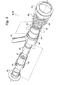
- Fig. 1 a partial view of an exemplary embodiment of a multipoint injector in accordance with the invention is shown in Fig. 1 and is designated generally by reference character 100.
- Other embodiments of multipoint injectors in accordance with the invention, or aspects thereof, are provided in Figs. 2-45 , as will be described.
- the systems and methods of the invention can be used to provide multipoint swirl stabilized discrete injection atomization, with particular applications in lean direct injection, to improve flame stabilization.
- the benefits of multipoint injection are added to the benefits of the stability provided by a central recirculation zone as in airblast injectors, rather than on numerous distributed zones as in traditional multipoint injection systems.
- injector 100 includes a mounting flange 102 with associated inlet fittings 104 for connecting injector 100 with a fuel source, such as fuel lines in a gas turbine engine.
- Feed arm 106 structurally connects between mounting flange 102 and nozzle body 108, and places inlet fittings 104 in fluid communication with nozzle body 108.
- Nozzle body 108 of injector 100 is mounted in an upstream wall of combustor 10 to issue a flow of fuel and air for combustion therein.
- Feed arm 106 includes three concentric fuel conduits 110, 112, and 114, each of which conducts fuel from one of the inlet fittings 104 to a respective one of three fuel circuits or stages, which are described in greater detail below.
- the components of nozzle body 108 generally form an outer air swirler 116, multipoint injection ring 118, an inner air swirler 120, and an inner fuel injector 122.
- FIG. 3 the individual components of nozzle body 108 are shown separated from one another.
- a downstream portion of feed arm 106 forms an outer heat shield 124, and an upstream portion 126 of outer heat shield 124 forms an exterior of nozzle body 108.
- Air body 128 is mounted downstream of the upstream portion 126 of outer heat shield 124, and is radially outboard of the downstream portion thereof.
- a fuel injector body 130 defines a longitudinal central axis A and has a fuel inlet 132 defined therein for receiving fuel from an external source.
- Fuel injector body 130 includes an inner fuel sleeve mounted inboard of an outer fuel sleeve, as described below with reference to Fig. 9 . Fuel passages are defined between the outer and inner fuel sleeves of the injector body as described in greater detail below.
- a distributor ring 136 is mounted to the downstream end of injector body 130.
- Distributor ring 136 includes a plurality of fuel inlets aligned with respective fuel outlets of fuel injector body 130, as described in greater detail below with reference to Figs. 18-19 .
- Distributor ring 136 includes a plurality of fuel swirlers defined in an upstream surface thereof, and a plurality of air swirlers defined in a downstream surface thereof, as described in greater detail below. Each of the fuel and air swirlers is positioned to impart swirl on an individual spray point, and together the multiple spray points form a multipoint injector ring.
- Air body 128 is in the general form of a ring is mounted outboard of outer heat shield 124, with its downstream portion wrapping around the downstream facing portion of distributor ring 136.
- Air cap 140 is mounted to air body 128 to form outer air swirler 116 of nozzle body 108 (shown in Fig. 2 ).
- Upstream inner heat shield 142 is mounted to the upstream end of nozzle body 108 inboard of fuel injector body 130.
- a downstream inner heat shield 134 is mounted inboard of injector body 130. Together, upstream and downstream inner heat shields 142 and 134 form a portion of inner air swirler 120 (shown in Fig. 2 ) and provide thermal shielding for fuel passing through injector body 130.
- air body 128 directs air for outer air swirler 116 of injector body 108, and provides a portion of the air used in the air swirlers of distributor ring 136.
- Air for outer air swirler 116 passes through swirl vanes 144, which together with air cap 140 (shown in Fig. 3 ) form an axial outer air swirler 116 of nozzle body 108.
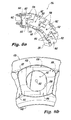
- a portion of the air for the swirler of distributor ring 136 is diverted prior to encountering swirl vanes 144 by passing through radial ports 146, and on to a plurality of air outlets 138.
- Outlets 138 are circumferentially spaced apart with respect to central axis A, with each air outlet 138 being aligned with a respective spray point of distributor ring 136 when air body 128 and distributor ring 136 are mounted together as shown in Fig. 2 . While the total number of air outlets 138 is s fifteen, for sake of clarity only some of the air outlets 138 are labeled in Figs. 4-5 . Another portion of the air for the fuel swirlers of distributor ring 136 is diverted from the inner air swirler 120 of nozzle body 108, shown in Fig. 2 , by inner lip 148, identified in Fig. 5 . As shown in Fig.
- each air outlet 138 of air body ring 128 includes an aerodynamically angled downstream surface 150 configured to be aerodynamically wiped to resist carbon formation thereon. Even if fuel flow for a given injection point is staged off, the aerodynamic wiping of the respective surface 150 can continue as air continues to flow through the injection point. This continued air flow can additionally draw out small, purging flows of fuel from the respective injection point, reducing coking within the inactive fuel stage. Only one of the angled downstream surfaces 150 is identified in Fig. 4 , for sake of clarity.
- distributor ring 136 has swirlers defined in its upstream and its downstream facing surfaces.
- air swirlers 152 are defined in a downstream face of distributor ring 136.
- Each air swirler 152 includes two inboard air inlets 154 in fluid communication therewith defined in a radially inboard surface 156 of distributor ring 136.
- Each air swirler 152 also includes two outboard air inlets 158 in fluid communication therewith defined in a radially outboard surface 160 of distributor ring 136.
- Each of the air inlets 154 and 158 of air swirlers 152 is radially off set with respect to the respective spray orifice 162 thereof to form a radial air swirler about the respective spray orifice 162.
- the volumes of air swirlers 152 are defined between distributor ring 136 and air body ring 128.
- Fig. 6b schematically shows how inlets 154 and 158 are covered by air body 128, so that in order for air to pass through each outlet 138, it must pass through the tangentially offset inlets 154 and 158 thereby imparting swirl onto the air flow through each outlet 138.
- Each air swirler 152 is aligned with a respective air outlet 138, and each air outlet 138 is aligned downstream of a respective spray orifice 162 for injecting a swirling flow of fuel and air for air-assisted injection of fuel.
- each fuel swirler 164 includes a central swirl chamber 166, and two inlet chambers 168.
- Each inlet chamber 168 is fluidly connected to its respective central swirl chamber 166 by an offset fuel passage 170 configured to impart clockwise rotation on fuel in the respective central swirl chamber 166, as viewed in Fig. 8 .
- any suitable number of fuel and air swirlers can be circumferentially spaced around the axis of distributor ring 136, and that the swirl chambers can be configured for counter clockwise swirl, or can be set up with any configuration of counter- or co- rotational patterns among the swirlers without departing from the spirit and scope of the invention.
- Fuel swirlers 164 and air swirlers 152 impart swirl onto fuel and air issuing from each injection point through the respective spray orifice 162 of distributor ring 136 and air outlet 138 of air body 128.
- injector body 130 includes an inner fuel sleeve 172, which when assembled is mounted inboard of outer fuel sleeve 174 to form injector body 130.
- the assembly of inner and outer fuel sleeves 172 and 174 can be done by any suitable process, including the process combining thermal resizing and brazing describe in commonly owned U.S. Patent Application Publication No. 2009/0140073 , for example.
- Fuel inlet 132 of injector body 130 is formed in outer fuel sleeve 174 to accommodate separate fuel flows from concentric conduits 110, 112, and 114.
- Inner air swirler body 176 having axial swirl vanes, is mounted on central post 178 of inner fuel sleeve 172.
- Fuel inlet 132 includes an inner bore 186 through which conduit 114 passes to feed fuel to a first stage fuel injector. There is a clearance between bore 186 and conduit 114, when assembled, that allows passage of fuel from conduit 112 (shown in Fig. 9 ) into channel 182 (also shown in Fig. 9 ) to a second stage of fuel injector points. Conduit 112 mates with the large diameter portion 190 of bore 186. Fuel inlet 132 also includes an outer passage 188 for conducting fuel from conduit 110 into channel 184 (shown in Fig. 9 ) for supplying a third stage of injector points. A cantilever 192 is provided to connect the structure of inner bore 186 to the main portion of outer fuel sleeve 174.
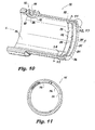
- Channel 194 forms a portion of the third stage fuel circuit.
- Channel 194 is a generally annular channel set in from the main inner surface 196 of outer fuel sleeve 174.
- Channel 194 runs in a circumferential direction with respect to axis-A, but is interrupted at its top most portion, as oriented in Fig. 10 , by a land 198 that is flush with the rest of the main inner surface 196.
- Fig. 11 shows a channel 194 and land 198 in cross-section. The thicknesses of outer fuel sleeve 174 and channel 194 are somewhat exaggerated in Fig. 11 for sake of clarity.
- Channel 194 is not concentric with the adjacent inner and outer diameters of inner fuel sleeve 174. Rather, channel 194 is eccentric with respect to main inner surface 196. As shown in Figs. 11 and 13 , channel 194 is relatively deep at a position near land 198, i.e., near the top of outer fuel sleeve 174 as oriented in Fig. 10 . As shown in Figs. 11 and 14 , channel 194 is relatively shallow at a position near the bottom of outer fuel sleeve 174 as oriented in Fig. 10 . The eccentricity of channel 194 accounts for pressure drop to allow for even flow to all of the injection points of the third fuel stage.
- Channel 194 is a main circumferential channel that is in fluid communication with adjacent circumferential channel 200, which has a constant depth around its circumference, interrupted only by land 198.
- Third stage fuel bores 202 extend from downstream surface 204 of outer fuel sleeve 174.
- Fuel bores 202 can be formed, for example, by drilling in an axial direction from downstream surface 204 into channel 200.
- Fig. 12 shows one of the fuel bores 206 of the second fuel stage, which is described in greater detail below. There are a total of six fuel bores 206, however, only one fuel bore 206 is identified with a reference character in Fig. 10 for sake of clarity.
- inner fuel sleeve 172 includes portions of the first, second, and third stage fuel circuits.
- Fuel bore 180 mates with conduit 114 (shown in Fig. 20 ) to allow passage of fuel into central post 178, which when fully assembled leads to a centerline injection point of the first fuel stage.
- Channel 182 is defined in the outboard surface of inner fuel sleeve 172 and extends from fuel bore 180 in an axial direction to circumferential channel 183 to form a portion of the second stage fuel circuit.
- Enlarged portion 181 of bore 180 allows for a clearance between conduit 114 and bore 180 at the upstream end of channel 182 to allow fuel from conduit 112 to pass into the second stage fuel circuit.
- a u-shaped channel 184 defined in the radially outer surface of inner fuel sleeve 172 and extending in a generally axial direction, fluidly connects outer passage 188 (shown in Fig. 10 ) and conduit 110 to the third stage fuel circuit.
- An upstream opening 208 in central post 178 allows for assembly of fuel injector components inside central post 178.
- Second stage fuel from conduit 112 passes through bore 186 (shown in Fig. 10 ) and into fuel bore 180 and channel 182.
- Main inner surface 196 of outer fuel sleeve 174 encloses channel 182, and land 198 prevents second stage fuel in channel 182 from reaching channel 184 or channel 194 of outer fuel sleeve 174.
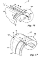
- channel 182 joins circumferential channel 183. Fuel in channel 183 can feed out through fuel bores 206, as indicated by the arrow labeled "fuel out" in Fig. 16 .
- Fuel channel 183 narrows in the axial direction (i.e., it is wider near the top of Fig. 15 , and narrower at the bottom) in order to provide even flow to all of the second stage injection points. This can be seen by comparing the axial width of channel 183 as shown in Figs. 23 and 25 .
- conduit 110 feeds second stage fuel through outer passage 188 (shown in Fig. 10 ) into channel 184 as shown in Fig. 17 .
- Main inner surface 196 of outer fuel sleeve 174 encloses channel 184 except at the downstream ends thereof, which are in fluid communication with channel 194.
- third stage fuel from channel 184 feeds channel 200 and fuel bores 202 of the third fuel stage.
- fuel bores 202 and 206 of outer fuel sleeve 174 are in fluid communication with the fuel swirlers 164 of distributor ring 136.
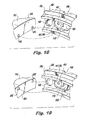
- Two of the fuel bores 206 of the second stage fuel circuit are shown in Fig. 18 , which shows schematically where the fuel bores 206 feed into inlet chambers 168 of a fuel swirler 164.
- Fig. 19 shows schematically where two of the fuel bores 202 of the third stage fuel circuit feed into inlet chambers 168 of another fuel swirler 164.
- Each fuel swirler 164 is in fluid communication with two fuel bores 202 or 206 of outer fuel sleeve 174.
- swirler configuration of swirlers 164 is exemplary, and those skilled in the art will readily appreciate that any suitable swirler configurations can be used without departing from the spirit and scope of the invention.
- swirler configurations shown in commonly owned, copending U.S. Patent Application Serial No. 12/535,122 Publication No. 2011/0031333 ) can be used as appropriate from application to application.
- the first fuel stage includes conduit 114 and inner fuel injector 122, which is a pressure atomizer.
- the second fuel stage includes the space between conduits 112 and 114, includes enlarged bore portion 181 and bore 186, channels 182 and 183, and the spray orifices 162 associated with the second stage fuel bores 206 as described above with reference to Fig. 16 .
- the third fuel stage includes the space between conduits 110 and 112, passage 188 (shown in Fig. 10 ), u-shaped channel 184 of inner fuel sleeve 172 (shown in Fig. 9 ), channels 194 and 200 of outer fuel sleeve 174 (shown in Fig. 10 ), and the spray orifices 162 associated with the third stage fuel bores 202 as described above with reference to Fig. 17 .
- Inner air swirler body 176, upstream inner heat shield 142, and downstream inner heat shield 134 define inner air swirler 120, which provides a swirling flow of air outboard of spray from inner fuel injector 122, and inboard of spray orifices 162.
- Air cap 140 and air body 128 define outer air swirler 116, which provides a swirling flow of air outboard of spray orifices 162.
- Inner air swirler 120 and outer air swirler 116 form inner and outer air circuits, respectively. These inner and outer air circuits can induce more or less spin into the fuel spray from the multiple injection points, depending on whether the air circuits are co- or counter-rotating. Those skilled in the art will readily appreciate that either co-rotating or counter-rotating configurations can be used from application to application.
- each individual air swirler 152 shown in Fig. 6a ) of distributor ring 136 for air assisted injection at each corresponding injection point.
- a first portion of the air for swirlers 152 is supplied from outboard of air body 128 through radial ports 146, through the annular space between air body 128 and outer heat shield 124, and into air swirlers 152 through their respective outboard air inlets 158 (shown in Fig. 6a ).
- Each radial port 146 is aligned with the upstream end of a swirl vane 144 to help force air into the radial port 146 (as shown in Fig. 5 ).
- a second portion of the air for swirlers 152 is supplied from inboard of air body 128 from inner air swirler 120.
- Inner lip 148 protrudes into inner air swirler 120 and directs a portion of the air flow therefrom into inboard inlets 154 (shown in Fig. 6a ) of air swirlers 152.
- Heat shielding is provided for the fuel circuits of all three fuel stages as they flow from feed arm 106 to the downstream end of nozzle body 108.
- the air flowing through and around air blast fuel injectors can be in excess of 400°F, which is hot enough to decompose fuel into its constituent parts. If left unchecked, fuel reaching these temperatures can form coke deposits in the fuel passages, which can restrict or even block fuel flow.
- the fuel passages in nozzle body 108 are thermally isolated from external conditions.
- Feed arm 106 includes an insulation gap 210 for thermally isolating all three of the conduits 110, 112, and 114 passing therethrough from external conditions.
- the first stage fuel circuit includes an insulation gap 212 between inner fuel sleeve 172 and conduit 114.
- a seal 185 (shown in Fig. 20 ) seals between conduit 114 and enlarged portion 181 of bore 180 to separate the second fuel stage from insulating gap 212.
- An axial insulation gap 214 is provided between inner air swirler body 176 and central post 178 to thermally isolate fuel flowing through centerline fuel passage 216 to inner fuel injector 122 from air flowing through inner air swirler 120.
- Upstream and downstream inner heat shields 142 and 134 are spaced radially apart from inner fuel sleeve 172 to provide an insulation gap 218 therebetween.
- Gap 218 provides thermal isolation to second and third stage fuel passing between inner and outer fuel sleeves 172 and 174 from air flowing through inner air swirler 120.
- Outer heat shield 124 is spaced radially apart from outer fuel sleeve 174 to provide an insulation gap 220 therebetween.
- Gap 220 provides thermal isolation to the second and third stage fuel passing between inner and outer fuel sleeves 172 and 174 from air flowing through outer air swirler 116, and from air flowing between outer heat shield 124 and air body 128.
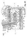
- FIG. 21 an enlargement of the portion of nozzle body 108 indicated in Fig. 20 is shown.
- Fig. 21 shows insulating gaps 218 and 220. Channels 182 and 183 between inner and outer fuel sleeves 172 and 174 are shown, as described above.
- the cross-section of the view in Fig. 21 cuts through spray orifice 162 to show how this fluidly connects central swirl chamber 166 of fuel swirler 164 to air swirler 152 of distributor ring 136. Lip 148 and radial ports 146 of air body 128 for feeding air to air swirler 152 are also shown.
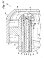
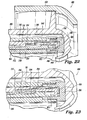
- Fig. 22 shows a similar cross-section as that shown in Fig. 21 , however, the cross-section in Fig.
- FIG. 22 is taken through fuel bore 202 of the third fuel stage.
- Channels 184 and 194 and fuel bore 202 are shown in fluid communication with each other for supplying fuel to fuel bore 202, which is in fluid communication with inlet chamber 168 of fuel swirler 164.
- a portion of channel 183 of the second fuel stage is also shown in Fig. 22 , in fluid isolation from channel 184.
- Fig. 23 shows channels 184, 194, and 200 of the third fuel stage filled with fuel being supplied to fuel bore 202 and inlet chamber 168 of fuel swirler 164.
- Channel 183 of the second fuel stage is shown without fuel therein.
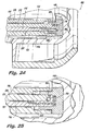
- Figs 24 and 25 correspond to Figs.
- FIG. 22 and 23 being similar cross-sections through a different fuel bore 202 of the third fuel stage, showing the third stage fuel passages without fuel and with fuel, respectively.
- Comparing Fig. 22 to Fig. 24 , and comparing Fig. 23 with Fig. 25 shows the eccentricity of channel 194 in outer fuel sleeve 174.
- channel 194 is relatively deep, and in the opposite side of outer fuel sleeve 174, Figs. 23 and 25 , channel 194 is relatively shallow. This eccentricity of channel 194 compensates for pressure drop in the third fuel circuit to help ensure even flow to all of the fuel bores 202 as described above.
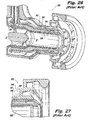
- FIG. 26 an illustration is shown of an exemplary airblast fuel injector 300, for example, a PN 158998 fuel injector available from Goodrich Corporation of Charlotte, North Carolina.
- Injector 300 is a prefilming airblast injector and includes an outer air swirler 302, a prefilmer 304, a fuel swirler 306, and an inner air swirler 308, all defining a central axis B.
- Fig. 27 shows an enlarged view of the downstream ends of air cap 302, a prefilmer 304, a fuel swirler 306, and an inner air swirler 308.
- a fuel circuit 310 passes between prefilmer 304 and fuel swirler 306.
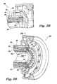
- injector 300 of Fig. 26 is shown converted to a multipoint configuration. This example is presented in order to exemplify the simplicity and space minimizing features of the present invention.
- the portions of Fig. 28 shown in phantom lines indicate where components of injector 300 are modified, and Fig. 29 shows multipoint components mounted in injector 300.
- Three multipoint injector components namely distributor ring 312, fuel orifice ring 314, and air swirler ring 316 are all that is required in order to convert the fuel dispersion function of prefilmer 304 and fuel swirler 306 to a 40 point air assisted pressure atomizing injector, all the while retaining the flame stabilizing benefit of a strong swirl imparted by outer air swirler 302 and inner air swirler 308.
- the exemplary modifications shown in Figs. 28-29 can be performed as a retrofit on existing traditional injectors, and that the modifications can also be performed at the design level to produce new injectors with the modified design.
- the modifications provide the benefits of air assisted multipoint lean direct injection for existing gas turbine engines without requiring modification to other existing engine components, since the form factor envelope needed for the modified injectors is not impacted.
- distributor ring 312 is shown separately.
- the downstream surface 318 of distributor ring 312 is a generally diverging, frustoconical surface.
- two arrays of radial fuel swirlers are defined in downstream face 318.
- the first array of fuel swirlers 320 is radially outboard of the second array of swirlers 322.
- Each of the fuel swirlers 320 and 322 has a radially offset outboard inlet 324 and a radially offset inboard inlet 326.
- the radially offset inlets 324 and 326 impart swirl onto fuel flowing into the central chamber of each fuel swirler 320 and 322.
- the outer circumference 328 and upstream surface 330 of distributor ring 312 are castellated so that fuel can flow from fuel circuit 310 (shown in Fig. 29 ) through gaps 332 into outboard inlets 324 (shown in Fig. 30 ) of fuel swirlers 320 and 322.
- fuel circuit 310 shown in Fig. 29
- outboard inlets 324 shown in Fig. 30
- not all of the gaps 332 are identified with reference characters in Fig. 31 .
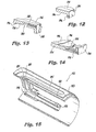
- Fuel orifice ring 314 is shown separate from the other components of injector 300 as viewed from downstream and upstream, respectively.
- Fuel orifice ring 314 includes a main downstream section 334 that is generally frustoconical.
- An inboard array of fuel outlet orifices 336 and an outboard array of fuel outlet orifices 338 are defined through section 334, for a total of forty outlet orifices.
- the multipoint array would have a total flow number of 60.
- Fuel orifices 336 and 338 are circumferentially spaced apart with respect to the central axis B (identified by reference characters in Fig. 26 ).
- An inboard flange 340 and an outboard flange 342 extend axially upstream from section 334 for engagement with the components of injector 300, as shown in Fig. 29 .
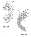
- air swirler ring 316 is shown as viewed from a point downstream and from a point upstream, respectively.
- Main section 344 of air swirler ring 316 is generally frustoconical and includes inboard and outboard arrays of outlet orifices 346 and 348, respectively, corresponding to fuel swirlers 322 and 320 and fuel orifices 336 and 338 described above.
- Orifices 346 and 348 are outlets for air and fuel issuing from injector 300, as described below in greater detail.
- not all of the outlet orifices 346 and 348 are identified with reference characters in Figs. 34 and 35 . As shown in Fig.
- each outlet orifice 346 and 348 has an air swirler 350 in fluid communication therewith.
- the air swirlers 350 are single-inlet air swirlers defined in the main upstream surface of main section 344. Between adjacent swirlers 350 there is a land 352 formed in the main upstream surface of main section 344. Swirlers 350 are radially offset with respect to the respective outlet orifices 346 and 348 to induce swirl on air flowing therethrough.
- An inboard air scoop 354 and an outboard air scoop 356 extend generally upstream from main section 344 to function as air inlets by diverting airflow from the inner and outer air circuits of injector 300, respectively, into swirlers 350.
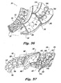
- FIG. 36 and 37 the engagement of distributor ring 312, fuel orifice ring 314, and air swirler ring 316 is indicated as viewed from points downstream and upstream respectively.
- the downstream face 318 of distributor ring 312 is mounted to the upstream surface of section 344 of fuel orifice ring 314.
- the outer circumference 328 of distributor ring 312 engages outboard flange 342 of fuel orifice ring 314.
- the gaps 332 allow for fuel flow to the swirlers 320 and 322 of distributor ring 312, as described above.
- Distributor ring 312 and fuel orifice ring 314 are mounted so that each respective swirler 322 and 320 is aligned with a respective fuel orifice 336 and 338.
- Land 352 of air swirler ring 316 is mounted to the downstream surface of main section 344 of fuel orifice ring 314.
- Air swirler ring 316 is mounted to fuel orifice ring 314, oriented so that each respective outlet orifice 346 and 348 of air swirler ring 316 is aligned with a respective fuel orifice 336 and 338.
- air swirler ring 316 allows clearance between air scoop 354 and inboard flange 340, as well as between air scoop 356 and outboard flange 342 so that air can be supplied to air swirlers 350 for air-assisted injection of fuel from fuel orifices 336 and 338.
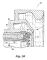
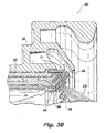
- Figs. 38 and 39 the outlet portion of injector 300 is shown with the multipoint modification.
- the assembly of distributor ring 312, fuel orifice ring 314, and air swirler ring 316 is engaged to injector 300 by mounting fuel orifice ring 314 to prefilmer 304 and fuel swirler 306 as described above.
- fuel orifice ring 314 seals of the downstream end of fuel circuit 310 so that fuel must pass through fuel swirlers 322 and 320 and on through fuel orifices 336 and 338 in order to reach the combustor downstream.
- prefilmer 304 and fuel swirler 306 serve as the inner and outer fuel sleeves for modified injector 300.
- FIG. 39 schematically indicates fuel and airflow through the modified portion of injector 300.
- spray 358 is only indicated for one injection point in Fig. 39 , however, it is intended that all of the injection points produce a spray simultaneously.
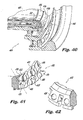
- injector 400 is similar in most aspects to injector 300 described above, including outer air swirler 402 and inner air swirler 408. However, injector 400 does not include a multipoint air swirler ring. Rather, the swirlers and fluid outlets are configured and adapted to inject a swirling, pressure atomized spray of fuel therefrom. Injector 400 thus provides for multi-point lean direct injection without individualized assist air for each injection point.
- An additional difference between injector 400 and injector 300 described above is the shape of the respective distributor rings and fuel orifice rings.
- distributor ring 412 and fuel orifice ring 414 are shaped so that inboard fuel orifices 436 are directed to a radially converging direction and outboard fuel orifices 438 are directed axially downstream, i.e., fuel orifices 438 do not converge or diverge.
- distributor ring 412 includes through bores 425 for feeding the outboard inlets of inboard swirlers 422 and the inboard inlets of outboard swirlers 420.
- Swirlers 420 are defined in an axially downstream facing surface 419, and swirlers 422 are defined in a frustoconical surface 418 to engage the interior downstream facing and frustoconical surfaces of fuel orifice ring 414.
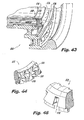
- FIG. 43-45 another exemplary embodiment of an injector 500 is shown.
- Injector 500 is similar in most respects to injector 400 described above.
- distributor ring 512 and fuel orifice ring 514 are configured so that all of the fuel orifices 536 and 538 are directed in an axially downstream direction.
- all of the fuel swirlers 522 and 520 are formed in a surface 518 of distributor ring 512 that faces axially downstream.
- injectors 400 and 500 are described above in the exemplary context of no air-assist, those skilled in the art will readily appreciate that air swirler rings, like air swirler ring 316 described above, can be added to injectors 400 and 500 for applications where air-assist is advantageous.
- injectors 300, 400 and 500 are advantageously configured so that the largest pressure drop in the multipoint fuel circuit occurs at the fuel orifices. In retrofit applications, this can be accomplished by opening or widening the metering slots of the original, umnodified design if necessary.
- the multipoint configurations described herein allow for control of location and orientation of injection, as well as the ability to intersperse air and fuel inlets, enabling very rapid mixing and more flexibility to control the flow field.
- the ability to deliberately direct the fuel to create a desired pattern is a distinct advantage over a prefilming airblast injector, which is mostly dependent on the air flow field to influence fuel dispersion.
- the multipoint configurations described herein still retain the advantage of a stabilizing, dominant, swirling air flow field typical of airblast injectors.
- the multipoint configurations described herein provide for the benefits of lean direct injection and air-assisted lean direct injection without the need to alter the form factor or envelope of existing air blast fuel injectors.
- multipoint injectors integrated with a traditional engine architecture in accordance with the invention include simpler heat management, neutral weight gain (compared to air blast injectors), simplified construction, and the option to retrofit existing engines. While described above with exemplary numbers of injection points, any suitable number of individual injection points can be used from application to application without departing from the invention.
- multipoint injectors in accordance with the invention can be practiced in any other suitable spray application.
- suitable applications include (but are not limited to) fuel cell reformers, fire suppression, misting, and rich burn applications.
- Exemplary embodiments have been described above with air-assisted injection, however, any suitable gas can be used for gas assisted injection in accordance with the invention.
- the exemplary injectors described herein can be constructed using conventional machining practices without etching or macro laminate, however those skilled in the art will readily appreciate that any suitable processes can be used to construct injectors as described above without departing from the spirit and scope of the invention.
- the multipoint injection described above includes injection points that converge axially, or that are aligned axially. However, it is also contemplated that some or all of the injection points can have spray directions that diverge from the axial direction.
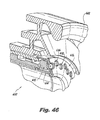
- Figs. 46-49 another exemplary embodiment of a fuel injector 600 is shown, in which the spray direction diverges from the central axis. As shown in Fig. 46 , injector 600 includes a distributor ring 612, fuel orifice ring 614, and air swirler ring 616 much like those described above, however, these three rings are configured so that all of the fuel and air outlets diverge away from the central axis of injector 600.
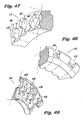
- Distributor ring 612 shown in Fig.
- FIG. 47 includes inboard and outboard swirlers 620 and 622 defined in diverging down stream face 618, all of which define a diverging downstream aspect for distributor ring 612.
- the upstream portion of distributor ring 612 shown in Fig. 48 , includes features similar to distributor ring 312 described above, including gaps 632 for passage of fuel around distributor ring 612.
- air swirler ring 616 includes inboard and outboard orifices 638 and 636, respectively, much as described above.
- air swirlers 650 which operate much as air swirlers 350 described above, with the outboard inlets into swirlers 650 being open to receive air in a generally radial direction from outboard thereof. Since the components of injector 600 are configured do inject a multipoint spray of fuel and air in a diverging direction toward the converging flow form the outer air swirler 602, shown in Fig. 46 , the interaction of the converging outer air flow with the diverging flow of air and fuel can provide enhanced fuel distribution and atomization.
- the methods and systems of the present invention provide for multipoint swirl stabilized discrete injection atomization.
- Mechanical features are incorporated to atomize fuel, therefore the methods and systems of the present invention avoid the disadvantages of relying on air for atomization as in a jet in cross flow.
- Lean direct injection, with optional air assist provided at each injection point enables more efficient combustion and lower emissions.
- staging of fuel circuits for improved turndown ratios is more easily accomplished than in air blast injectors.
- the benefits of multipoint injection are added to the benefits of the stability provided by a central recirculation zone as in airblast injectors, rather than on numerous individual distributed zones.
- the exemplary configurations can be fit into the form envelopes of airblast fuel injectors. While the apparatus and methods of the subject invention have been shown and described with reference to preferred embodiments, those skilled in the art will readily appreciate that changes and/or modifications may be made thereto without departing from the spirit and scope of the subject invention.
Landscapes
- Engineering & Computer Science (AREA)
- Chemical & Material Sciences (AREA)
- Combustion & Propulsion (AREA)
- Mechanical Engineering (AREA)
- General Engineering & Computer Science (AREA)
- Fuel-Injection Apparatus (AREA)
- Nozzles (AREA)
Applications Claiming Priority (1)
| Application Number | Priority Date | Filing Date | Title |
|---|---|---|---|
| US13/110,371 US8616471B2 (en) | 2011-05-18 | 2011-05-18 | Multipoint injectors with standard envelope characteristics |
Publications (3)
| Publication Number | Publication Date |
|---|---|
| EP2525152A2 true EP2525152A2 (fr) | 2012-11-21 |
| EP2525152A3 EP2525152A3 (fr) | 2017-09-13 |
| EP2525152B1 EP2525152B1 (fr) | 2018-12-12 |
Family
ID=46049250
Family Applications (1)
| Application Number | Title | Priority Date | Filing Date |
|---|---|---|---|
| EP12165814.0A Not-in-force EP2525152B1 (fr) | 2011-05-18 | 2012-04-26 | Anneau d'injection multipoint |
Country Status (2)
| Country | Link |
|---|---|
| US (1) | US8616471B2 (fr) |
| EP (1) | EP2525152B1 (fr) |
Cited By (6)
| Publication number | Priority date | Publication date | Assignee | Title |
|---|---|---|---|---|
| US9562691B2 (en) | 2013-09-30 | 2017-02-07 | Rolls-Royce Plc | Airblast fuel injector |
| EP3156732A1 (fr) * | 2015-10-16 | 2017-04-19 | Delavan, Inc. | Injecteurs à jet porté |
| US9927126B2 (en) | 2015-06-10 | 2018-03-27 | General Electric Company | Prefilming air blast (PAB) pilot for low emissions combustors |
| CN109073227A (zh) * | 2016-04-15 | 2018-12-21 | 索拉透平公司 | 用于内燃机的燃料喷射器和分级燃料输送方法 |
| US10184665B2 (en) | 2015-06-10 | 2019-01-22 | General Electric Company | Prefilming air blast (PAB) pilot having annular splitter surrounding a pilot fuel injector |
| EP3499126A1 (fr) * | 2017-12-15 | 2019-06-19 | Delavan, Inc. | Ensemble d'injecteurs de carburant |
Families Citing this family (21)
| Publication number | Priority date | Publication date | Assignee | Title |
|---|---|---|---|---|
| US8375548B2 (en) * | 2009-10-07 | 2013-02-19 | Pratt & Whitney Canada Corp. | Fuel nozzle and method of repair |
| US9745936B2 (en) | 2012-02-16 | 2017-08-29 | Delavan Inc | Variable angle multi-point injection |
| US10094352B2 (en) | 2012-02-16 | 2018-10-09 | Delavan Inc. | Swirl impingement prefilming |
| US9333518B2 (en) | 2013-02-27 | 2016-05-10 | Delavan Inc | Multipoint injectors |
| US20150107256A1 (en) * | 2013-10-17 | 2015-04-23 | Pratt & Whitney Canada Corp. | Combustor for gas turbine engine |
| US20140215828A1 (en) * | 2014-04-07 | 2014-08-07 | Electro-Motive Diesel, Inc. | Valve mounting fixture for an internal combustion engine |
| US9453461B2 (en) | 2014-12-23 | 2016-09-27 | General Electric Company | Fuel nozzle structure |
| WO2017116266A1 (fr) * | 2015-12-30 | 2017-07-06 | General Electric Company | Buses à combustible liquide pour chambres de combustion à double carburant |
| GB2548585B (en) * | 2016-03-22 | 2020-05-27 | Rolls Royce Plc | A combustion chamber assembly |
| EP3225915B1 (fr) * | 2016-03-31 | 2019-02-06 | Rolls-Royce plc | Injecteur de carburent et procédé de fabrication |
| US10502425B2 (en) * | 2016-06-03 | 2019-12-10 | General Electric Company | Contoured shroud swirling pre-mix fuel injector assembly |
| US10935245B2 (en) | 2018-11-20 | 2021-03-02 | General Electric Company | Annular concentric fuel nozzle assembly with annular depression and radial inlet ports |
| US11156360B2 (en) | 2019-02-18 | 2021-10-26 | General Electric Company | Fuel nozzle assembly |
| US12326259B2 (en) | 2020-11-24 | 2025-06-10 | Pratt & Whitney Canada Corp. | Fuel swirler for pressure fuel nozzles |
| EP4091802B1 (fr) * | 2021-05-17 | 2026-01-28 | Siemens Gamesa Renewable Energy A/S | Outil de zone sèche pour la création d'une zone sèche dans une pièce composite |
| US12059693B2 (en) | 2021-09-29 | 2024-08-13 | Kidde Technologies, Inc. | Nozzle geometry to create rotational vortex |
| CN114738798A (zh) * | 2022-03-21 | 2022-07-12 | 南京航空航天大学 | 一种预膜式气动多点燃油雾化装置 |
| DE102022202936A1 (de) | 2022-03-24 | 2023-09-28 | Rolls-Royce Deutschland Ltd & Co Kg | Düsenbaugruppe mit gegen eine Einströmung von Luft abgedichtetem zentralen Kraftstoffrohr |
| GB202307700D0 (en) | 2023-05-23 | 2023-07-05 | Rolls Royce Plc | An improved combustor apparatus |
| GB202307701D0 (en) | 2023-05-23 | 2023-07-05 | Rolls Royce Plc | An improved combustor apparatus |
| US12486984B2 (en) * | 2024-05-10 | 2025-12-02 | Pratt & Whitney Canada Corp. | Controlled gap fuel nozzle heat shield |
Citations (3)
| Publication number | Priority date | Publication date | Assignee | Title |
|---|---|---|---|---|
| US6533954B2 (en) | 2000-02-28 | 2003-03-18 | Parker-Hannifin Corporation | Integrated fluid injection air mixing system |
| US20090140073A1 (en) | 2007-11-30 | 2009-06-04 | Delavan Inc | Method of fuel nozzle construction |
| US20110031333A1 (en) | 2009-08-04 | 2011-02-10 | Delavan Inc | Multi-point injector ring |
Family Cites Families (5)
| Publication number | Priority date | Publication date | Assignee | Title |
|---|---|---|---|---|
| US3680793A (en) | 1970-11-09 | 1972-08-01 | Delavan Manufacturing Co | Eccentric spiral swirl chamber nozzle |
| US5409169A (en) * | 1991-06-19 | 1995-04-25 | Hitachi America, Ltd. | Air-assist fuel injection system |
| US6363726B1 (en) | 2000-09-29 | 2002-04-02 | General Electric Company | Mixer having multiple swirlers |
| US6755024B1 (en) | 2001-08-23 | 2004-06-29 | Delavan Inc. | Multiplex injector |
| US6854670B2 (en) * | 2002-05-17 | 2005-02-15 | Keihin Corporation | Fuel injection valve |
-
2011
- 2011-05-18 US US13/110,371 patent/US8616471B2/en not_active Expired - Fee Related
-
2012
- 2012-04-26 EP EP12165814.0A patent/EP2525152B1/fr not_active Not-in-force
Patent Citations (3)
| Publication number | Priority date | Publication date | Assignee | Title |
|---|---|---|---|---|
| US6533954B2 (en) | 2000-02-28 | 2003-03-18 | Parker-Hannifin Corporation | Integrated fluid injection air mixing system |
| US20090140073A1 (en) | 2007-11-30 | 2009-06-04 | Delavan Inc | Method of fuel nozzle construction |
| US20110031333A1 (en) | 2009-08-04 | 2011-02-10 | Delavan Inc | Multi-point injector ring |
Cited By (9)
| Publication number | Priority date | Publication date | Assignee | Title |
|---|---|---|---|---|
| US9562691B2 (en) | 2013-09-30 | 2017-02-07 | Rolls-Royce Plc | Airblast fuel injector |
| US9927126B2 (en) | 2015-06-10 | 2018-03-27 | General Electric Company | Prefilming air blast (PAB) pilot for low emissions combustors |
| US10184665B2 (en) | 2015-06-10 | 2019-01-22 | General Electric Company | Prefilming air blast (PAB) pilot having annular splitter surrounding a pilot fuel injector |
| EP3156732A1 (fr) * | 2015-10-16 | 2017-04-19 | Delavan, Inc. | Injecteurs à jet porté |
| US10132500B2 (en) | 2015-10-16 | 2018-11-20 | Delavan Inc. | Airblast injectors |
| CN109073227A (zh) * | 2016-04-15 | 2018-12-21 | 索拉透平公司 | 用于内燃机的燃料喷射器和分级燃料输送方法 |
| EP3499126A1 (fr) * | 2017-12-15 | 2019-06-19 | Delavan, Inc. | Ensemble d'injecteurs de carburant |
| US10830446B2 (en) | 2017-12-15 | 2020-11-10 | Delavan Inc. | Fuel injector assemblies |
| US11761634B2 (en) | 2017-12-15 | 2023-09-19 | Collins Engine Nozzles, Inc. | Fuel injector assemblies |
Also Published As
| Publication number | Publication date |
|---|---|
| EP2525152B1 (fr) | 2018-12-12 |
| EP2525152A3 (fr) | 2017-09-13 |
| US8616471B2 (en) | 2013-12-31 |
| US20120292408A1 (en) | 2012-11-22 |
Similar Documents
| Publication | Publication Date | Title |
|---|---|---|
| US8616471B2 (en) | Multipoint injectors with standard envelope characteristics | |
| US11525403B2 (en) | Fuel nozzle with integrated metering and flashback system | |
| US12007116B2 (en) | Dual pressure fuel nozzles | |
| US10415832B2 (en) | Multi-swirler fuel/air mixer with centralized fuel injection | |
| US10072848B2 (en) | Fuel injector with premix pilot nozzle | |
| US9239167B2 (en) | Lean burn injectors having multiple pilot circuits | |
| US10480472B2 (en) | Variable angle multi-point injection | |
| EP1323982B1 (fr) | Buse de combustible pour une turbine à gaz | |
| US8671691B2 (en) | Hybrid prefilming airblast, prevaporizing, lean-premixing dual-fuel nozzle for gas turbine combustor | |
| US9046039B2 (en) | Staged pilots in pure airblast injectors for gas turbine engines | |
| US10883719B2 (en) | Prefilming fuel/air mixer | |
| GB2486545A (en) | Aerodynamically enhanced fuel nozzle with rounded and straight sections | |
| JP2009074792A (ja) | Dlnガスタービンの二次燃料ノズル用トロイダルリングマニホルド | |
| EP2592351B1 (fr) | Brûleurs pilotes étagés dans des injecteurs d'air comprimé pour moteurs de turbine à gaz | |
| US8851401B2 (en) | Flat fan air assist injectors | |
| CN109945233B (zh) | 燃烧室及其雾化装置、航空燃气涡轮发动机 | |
| US11448175B1 (en) | Fuel nozzle |
Legal Events
| Date | Code | Title | Description |
|---|---|---|---|
| PUAI | Public reference made under article 153(3) epc to a published international application that has entered the european phase |
Free format text: ORIGINAL CODE: 0009012 |
|
| 17P | Request for examination filed |
Effective date: 20120426 |
|
| AK | Designated contracting states |
Kind code of ref document: A2 Designated state(s): AL AT BE BG CH CY CZ DE DK EE ES FI FR GB GR HR HU IE IS IT LI LT LU LV MC MK MT NL NO PL PT RO RS SE SI SK SM TR |
|
| AX | Request for extension of the european patent |
Extension state: BA ME |
|
| PUAL | Search report despatched |
Free format text: ORIGINAL CODE: 0009013 |
|
| AK | Designated contracting states |
Kind code of ref document: A3 Designated state(s): AL AT BE BG CH CY CZ DE DK EE ES FI FR GB GR HR HU IE IS IT LI LT LU LV MC MK MT NL NO PL PT RO RS SE SI SK SM TR |
|
| AX | Request for extension of the european patent |
Extension state: BA ME |
|
| RIC1 | Information provided on ipc code assigned before grant |
Ipc: F23R 3/34 20060101ALI20170807BHEP Ipc: F23R 3/28 20060101AFI20170807BHEP Ipc: F23D 11/10 20060101ALI20170807BHEP Ipc: F23D 11/38 20060101ALI20170807BHEP Ipc: F23R 3/12 20060101ALI20170807BHEP |
|
| GRAP | Despatch of communication of intention to grant a patent |
Free format text: ORIGINAL CODE: EPIDOSNIGR1 |
|
| STAA | Information on the status of an ep patent application or granted ep patent |
Free format text: STATUS: GRANT OF PATENT IS INTENDED |
|
| INTG | Intention to grant announced |
Effective date: 20180621 |
|
| GRAS | Grant fee paid |
Free format text: ORIGINAL CODE: EPIDOSNIGR3 |
|
| GRAA | (expected) grant |
Free format text: ORIGINAL CODE: 0009210 |
|
| STAA | Information on the status of an ep patent application or granted ep patent |
Free format text: STATUS: THE PATENT HAS BEEN GRANTED |
|
| AK | Designated contracting states |
Kind code of ref document: B1 Designated state(s): AL AT BE BG CH CY CZ DE DK EE ES FI FR GB GR HR HU IE IS IT LI LT LU LV MC MK MT NL NO PL PT RO RS SE SI SK SM TR |
|
| REG | Reference to a national code |
Ref country code: GB Ref legal event code: FG4D |
|
| REG | Reference to a national code |
Ref country code: CH Ref legal event code: EP |
|
| REG | Reference to a national code |
Ref country code: AT Ref legal event code: REF Ref document number: 1076532 Country of ref document: AT Kind code of ref document: T Effective date: 20181215 |
|
| REG | Reference to a national code |
Ref country code: DE Ref legal event code: R096 Ref document number: 602012054561 Country of ref document: DE |
|
| REG | Reference to a national code |
Ref country code: IE Ref legal event code: FG4D |
|
| REG | Reference to a national code |
Ref country code: NL Ref legal event code: MP Effective date: 20181212 |
|
| REG | Reference to a national code |
Ref country code: LT Ref legal event code: MG4D |
|
| PG25 | Lapsed in a contracting state [announced via postgrant information from national office to epo] |
Ref country code: ES Free format text: LAPSE BECAUSE OF FAILURE TO SUBMIT A TRANSLATION OF THE DESCRIPTION OR TO PAY THE FEE WITHIN THE PRESCRIBED TIME-LIMIT Effective date: 20181212 Ref country code: LV Free format text: LAPSE BECAUSE OF FAILURE TO SUBMIT A TRANSLATION OF THE DESCRIPTION OR TO PAY THE FEE WITHIN THE PRESCRIBED TIME-LIMIT Effective date: 20181212 Ref country code: FI Free format text: LAPSE BECAUSE OF FAILURE TO SUBMIT A TRANSLATION OF THE DESCRIPTION OR TO PAY THE FEE WITHIN THE PRESCRIBED TIME-LIMIT Effective date: 20181212 Ref country code: NO Free format text: LAPSE BECAUSE OF FAILURE TO SUBMIT A TRANSLATION OF THE DESCRIPTION OR TO PAY THE FEE WITHIN THE PRESCRIBED TIME-LIMIT Effective date: 20190312 Ref country code: LT Free format text: LAPSE BECAUSE OF FAILURE TO SUBMIT A TRANSLATION OF THE DESCRIPTION OR TO PAY THE FEE WITHIN THE PRESCRIBED TIME-LIMIT Effective date: 20181212 Ref country code: HR Free format text: LAPSE BECAUSE OF FAILURE TO SUBMIT A TRANSLATION OF THE DESCRIPTION OR TO PAY THE FEE WITHIN THE PRESCRIBED TIME-LIMIT Effective date: 20181212 Ref country code: BG Free format text: LAPSE BECAUSE OF FAILURE TO SUBMIT A TRANSLATION OF THE DESCRIPTION OR TO PAY THE FEE WITHIN THE PRESCRIBED TIME-LIMIT Effective date: 20190312 |
|
| REG | Reference to a national code |
Ref country code: AT Ref legal event code: MK05 Ref document number: 1076532 Country of ref document: AT Kind code of ref document: T Effective date: 20181212 |
|
| PG25 | Lapsed in a contracting state [announced via postgrant information from national office to epo] |
Ref country code: RS Free format text: LAPSE BECAUSE OF FAILURE TO SUBMIT A TRANSLATION OF THE DESCRIPTION OR TO PAY THE FEE WITHIN THE PRESCRIBED TIME-LIMIT Effective date: 20181212 Ref country code: GR Free format text: LAPSE BECAUSE OF FAILURE TO SUBMIT A TRANSLATION OF THE DESCRIPTION OR TO PAY THE FEE WITHIN THE PRESCRIBED TIME-LIMIT Effective date: 20190313 Ref country code: SE Free format text: LAPSE BECAUSE OF FAILURE TO SUBMIT A TRANSLATION OF THE DESCRIPTION OR TO PAY THE FEE WITHIN THE PRESCRIBED TIME-LIMIT Effective date: 20181212 Ref country code: AL Free format text: LAPSE BECAUSE OF FAILURE TO SUBMIT A TRANSLATION OF THE DESCRIPTION OR TO PAY THE FEE WITHIN THE PRESCRIBED TIME-LIMIT Effective date: 20181212 |
|
| PG25 | Lapsed in a contracting state [announced via postgrant information from national office to epo] |
Ref country code: NL Free format text: LAPSE BECAUSE OF FAILURE TO SUBMIT A TRANSLATION OF THE DESCRIPTION OR TO PAY THE FEE WITHIN THE PRESCRIBED TIME-LIMIT Effective date: 20181212 |
|
| PG25 | Lapsed in a contracting state [announced via postgrant information from national office to epo] |
Ref country code: PT Free format text: LAPSE BECAUSE OF FAILURE TO SUBMIT A TRANSLATION OF THE DESCRIPTION OR TO PAY THE FEE WITHIN THE PRESCRIBED TIME-LIMIT Effective date: 20190412 Ref country code: PL Free format text: LAPSE BECAUSE OF FAILURE TO SUBMIT A TRANSLATION OF THE DESCRIPTION OR TO PAY THE FEE WITHIN THE PRESCRIBED TIME-LIMIT Effective date: 20181212 Ref country code: CZ Free format text: LAPSE BECAUSE OF FAILURE TO SUBMIT A TRANSLATION OF THE DESCRIPTION OR TO PAY THE FEE WITHIN THE PRESCRIBED TIME-LIMIT Effective date: 20181212 Ref country code: IT Free format text: LAPSE BECAUSE OF FAILURE TO SUBMIT A TRANSLATION OF THE DESCRIPTION OR TO PAY THE FEE WITHIN THE PRESCRIBED TIME-LIMIT Effective date: 20181212 |
|
| PG25 | Lapsed in a contracting state [announced via postgrant information from national office to epo] |
Ref country code: IS Free format text: LAPSE BECAUSE OF FAILURE TO SUBMIT A TRANSLATION OF THE DESCRIPTION OR TO PAY THE FEE WITHIN THE PRESCRIBED TIME-LIMIT Effective date: 20190412 Ref country code: SK Free format text: LAPSE BECAUSE OF FAILURE TO SUBMIT A TRANSLATION OF THE DESCRIPTION OR TO PAY THE FEE WITHIN THE PRESCRIBED TIME-LIMIT Effective date: 20181212 Ref country code: RO Free format text: LAPSE BECAUSE OF FAILURE TO SUBMIT A TRANSLATION OF THE DESCRIPTION OR TO PAY THE FEE WITHIN THE PRESCRIBED TIME-LIMIT Effective date: 20181212 Ref country code: EE Free format text: LAPSE BECAUSE OF FAILURE TO SUBMIT A TRANSLATION OF THE DESCRIPTION OR TO PAY THE FEE WITHIN THE PRESCRIBED TIME-LIMIT Effective date: 20181212 Ref country code: SM Free format text: LAPSE BECAUSE OF FAILURE TO SUBMIT A TRANSLATION OF THE DESCRIPTION OR TO PAY THE FEE WITHIN THE PRESCRIBED TIME-LIMIT Effective date: 20181212 |
|
| REG | Reference to a national code |
Ref country code: DE Ref legal event code: R097 Ref document number: 602012054561 Country of ref document: DE |
|
| PLBE | No opposition filed within time limit |
Free format text: ORIGINAL CODE: 0009261 |
|
| STAA | Information on the status of an ep patent application or granted ep patent |
Free format text: STATUS: NO OPPOSITION FILED WITHIN TIME LIMIT |
|
| PG25 | Lapsed in a contracting state [announced via postgrant information from national office to epo] |
Ref country code: SI Free format text: LAPSE BECAUSE OF FAILURE TO SUBMIT A TRANSLATION OF THE DESCRIPTION OR TO PAY THE FEE WITHIN THE PRESCRIBED TIME-LIMIT Effective date: 20181212 Ref country code: AT Free format text: LAPSE BECAUSE OF FAILURE TO SUBMIT A TRANSLATION OF THE DESCRIPTION OR TO PAY THE FEE WITHIN THE PRESCRIBED TIME-LIMIT Effective date: 20181212 Ref country code: DK Free format text: LAPSE BECAUSE OF FAILURE TO SUBMIT A TRANSLATION OF THE DESCRIPTION OR TO PAY THE FEE WITHIN THE PRESCRIBED TIME-LIMIT Effective date: 20181212 |
|
| 26N | No opposition filed |
Effective date: 20190913 |
|
| REG | Reference to a national code |
Ref country code: CH Ref legal event code: PL |
|
| REG | Reference to a national code |
Ref country code: BE Ref legal event code: MM Effective date: 20190430 |
|
| PG25 | Lapsed in a contracting state [announced via postgrant information from national office to epo] |
Ref country code: MC Free format text: LAPSE BECAUSE OF FAILURE TO SUBMIT A TRANSLATION OF THE DESCRIPTION OR TO PAY THE FEE WITHIN THE PRESCRIBED TIME-LIMIT Effective date: 20181212 Ref country code: LU Free format text: LAPSE BECAUSE OF NON-PAYMENT OF DUE FEES Effective date: 20190426 |
|
| PG25 | Lapsed in a contracting state [announced via postgrant information from national office to epo] |
Ref country code: CH Free format text: LAPSE BECAUSE OF NON-PAYMENT OF DUE FEES Effective date: 20190430 Ref country code: LI Free format text: LAPSE BECAUSE OF NON-PAYMENT OF DUE FEES Effective date: 20190430 |
|
| PG25 | Lapsed in a contracting state [announced via postgrant information from national office to epo] |
Ref country code: BE Free format text: LAPSE BECAUSE OF NON-PAYMENT OF DUE FEES Effective date: 20190430 |
|
| PG25 | Lapsed in a contracting state [announced via postgrant information from national office to epo] |
Ref country code: TR Free format text: LAPSE BECAUSE OF FAILURE TO SUBMIT A TRANSLATION OF THE DESCRIPTION OR TO PAY THE FEE WITHIN THE PRESCRIBED TIME-LIMIT Effective date: 20181212 |
|
| PG25 | Lapsed in a contracting state [announced via postgrant information from national office to epo] |
Ref country code: IE Free format text: LAPSE BECAUSE OF NON-PAYMENT OF DUE FEES Effective date: 20190426 |
|
| PGFP | Annual fee paid to national office [announced via postgrant information from national office to epo] |
Ref country code: GB Payment date: 20200323 Year of fee payment: 9 |
|
| PGFP | Annual fee paid to national office [announced via postgrant information from national office to epo] |
Ref country code: FR Payment date: 20200319 Year of fee payment: 9 |
|
| PGFP | Annual fee paid to national office [announced via postgrant information from national office to epo] |
Ref country code: DE Payment date: 20200319 Year of fee payment: 9 |
|
| PG25 | Lapsed in a contracting state [announced via postgrant information from national office to epo] |
Ref country code: CY Free format text: LAPSE BECAUSE OF FAILURE TO SUBMIT A TRANSLATION OF THE DESCRIPTION OR TO PAY THE FEE WITHIN THE PRESCRIBED TIME-LIMIT Effective date: 20181212 |
|
| PG25 | Lapsed in a contracting state [announced via postgrant information from national office to epo] |
Ref country code: MT Free format text: LAPSE BECAUSE OF FAILURE TO SUBMIT A TRANSLATION OF THE DESCRIPTION OR TO PAY THE FEE WITHIN THE PRESCRIBED TIME-LIMIT Effective date: 20181212 Ref country code: HU Free format text: LAPSE BECAUSE OF FAILURE TO SUBMIT A TRANSLATION OF THE DESCRIPTION OR TO PAY THE FEE WITHIN THE PRESCRIBED TIME-LIMIT; INVALID AB INITIO Effective date: 20120426 |
|
| REG | Reference to a national code |
Ref country code: DE Ref legal event code: R119 Ref document number: 602012054561 Country of ref document: DE |
|
| GBPC | Gb: european patent ceased through non-payment of renewal fee |
Effective date: 20210426 |
|
| PG25 | Lapsed in a contracting state [announced via postgrant information from national office to epo] |
Ref country code: FR Free format text: LAPSE BECAUSE OF NON-PAYMENT OF DUE FEES Effective date: 20210430 Ref country code: GB Free format text: LAPSE BECAUSE OF NON-PAYMENT OF DUE FEES Effective date: 20210426 Ref country code: DE Free format text: LAPSE BECAUSE OF NON-PAYMENT OF DUE FEES Effective date: 20211103 |
|
| PG25 | Lapsed in a contracting state [announced via postgrant information from national office to epo] |
Ref country code: MK Free format text: LAPSE BECAUSE OF FAILURE TO SUBMIT A TRANSLATION OF THE DESCRIPTION OR TO PAY THE FEE WITHIN THE PRESCRIBED TIME-LIMIT Effective date: 20181212 |