EP2524728A2 - Apparatus for securely processing biological sample - Google Patents
Apparatus for securely processing biological sample Download PDFInfo
- Publication number
- EP2524728A2 EP2524728A2 EP20120168081 EP12168081A EP2524728A2 EP 2524728 A2 EP2524728 A2 EP 2524728A2 EP 20120168081 EP20120168081 EP 20120168081 EP 12168081 A EP12168081 A EP 12168081A EP 2524728 A2 EP2524728 A2 EP 2524728A2
- Authority
- EP
- European Patent Office
- Prior art keywords
- column
- semi
- sealing element
- permeable
- slot
- Prior art date
- Legal status (The legal status is an assumption and is not a legal conclusion. Google has not performed a legal analysis and makes no representation as to the accuracy of the status listed.)
- Granted
Links
- 239000012472 biological sample Substances 0.000 title claims abstract description 17
- 238000012545 processing Methods 0.000 title claims abstract description 17
- 238000007789 sealing Methods 0.000 claims abstract description 77
- 239000012528 membrane Substances 0.000 claims abstract description 40
- 239000007788 liquid Substances 0.000 abstract description 29
- 239000000523 sample Substances 0.000 abstract description 17
- 108091032973 (ribonucleotides)n+m Proteins 0.000 abstract description 3
- 108020004414 DNA Proteins 0.000 abstract description 3
- 102000004169 proteins and genes Human genes 0.000 abstract description 3
- 108090000623 proteins and genes Proteins 0.000 abstract description 3
- 102000040650 (ribonucleotides)n+m Human genes 0.000 abstract description 2
- 238000012864 cross contamination Methods 0.000 description 6
- 238000003780 insertion Methods 0.000 description 3
- 230000037431 insertion Effects 0.000 description 3
- 238000000034 method Methods 0.000 description 3
- 239000012858 resilient material Substances 0.000 description 2
- 238000012360 testing method Methods 0.000 description 2
- 239000002253 acid Substances 0.000 description 1
- 230000002411 adverse Effects 0.000 description 1
- 238000004891 communication Methods 0.000 description 1
- 238000013461 design Methods 0.000 description 1
- 230000000694 effects Effects 0.000 description 1
- 238000002474 experimental method Methods 0.000 description 1
- 239000000463 material Substances 0.000 description 1
- 238000005406 washing Methods 0.000 description 1
Images


Classifications
-
- B—PERFORMING OPERATIONS; TRANSPORTING
- B01—PHYSICAL OR CHEMICAL PROCESSES OR APPARATUS IN GENERAL
- B01L—CHEMICAL OR PHYSICAL LABORATORY APPARATUS FOR GENERAL USE
- B01L3/00—Containers or dishes for laboratory use, e.g. laboratory glassware; Droppers
- B01L3/50—Containers for the purpose of retaining a material to be analysed, e.g. test tubes
- B01L3/502—Containers for the purpose of retaining a material to be analysed, e.g. test tubes with fluid transport, e.g. in multi-compartment structures
- B01L3/5025—Containers for the purpose of retaining a material to be analysed, e.g. test tubes with fluid transport, e.g. in multi-compartment structures for parallel transport of multiple samples
- B01L3/50255—Multi-well filtration
-
- C—CHEMISTRY; METALLURGY
- C12—BIOCHEMISTRY; BEER; SPIRITS; WINE; VINEGAR; MICROBIOLOGY; ENZYMOLOGY; MUTATION OR GENETIC ENGINEERING
- C12N—MICROORGANISMS OR ENZYMES; COMPOSITIONS THEREOF; PROPAGATING, PRESERVING, OR MAINTAINING MICROORGANISMS; MUTATION OR GENETIC ENGINEERING; CULTURE MEDIA
- C12N15/00—Mutation or genetic engineering; DNA or RNA concerning genetic engineering, vectors, e.g. plasmids, or their isolation, preparation or purification; Use of hosts therefor
- C12N15/09—Recombinant DNA-technology
- C12N15/10—Processes for the isolation, preparation or purification of DNA or RNA
-
- B—PERFORMING OPERATIONS; TRANSPORTING
- B01—PHYSICAL OR CHEMICAL PROCESSES OR APPARATUS IN GENERAL
- B01L—CHEMICAL OR PHYSICAL LABORATORY APPARATUS FOR GENERAL USE
- B01L3/00—Containers or dishes for laboratory use, e.g. laboratory glassware; Droppers
- B01L3/50—Containers for the purpose of retaining a material to be analysed, e.g. test tubes
- B01L3/502—Containers for the purpose of retaining a material to be analysed, e.g. test tubes with fluid transport, e.g. in multi-compartment structures
-
- C—CHEMISTRY; METALLURGY
- C12—BIOCHEMISTRY; BEER; SPIRITS; WINE; VINEGAR; MICROBIOLOGY; ENZYMOLOGY; MUTATION OR GENETIC ENGINEERING
- C12M—APPARATUS FOR ENZYMOLOGY OR MICROBIOLOGY; APPARATUS FOR CULTURING MICROORGANISMS FOR PRODUCING BIOMASS, FOR GROWING CELLS OR FOR OBTAINING FERMENTATION OR METABOLIC PRODUCTS, i.e. BIOREACTORS OR FERMENTERS
- C12M1/00—Apparatus for enzymology or microbiology
- C12M1/12—Apparatus for enzymology or microbiology with sterilisation, filtration or dialysis means
-
- B—PERFORMING OPERATIONS; TRANSPORTING
- B01—PHYSICAL OR CHEMICAL PROCESSES OR APPARATUS IN GENERAL
- B01L—CHEMICAL OR PHYSICAL LABORATORY APPARATUS FOR GENERAL USE
- B01L2200/00—Solutions for specific problems relating to chemical or physical laboratory apparatus
- B01L2200/02—Adapting objects or devices to another
-
- B—PERFORMING OPERATIONS; TRANSPORTING
- B01—PHYSICAL OR CHEMICAL PROCESSES OR APPARATUS IN GENERAL
- B01L—CHEMICAL OR PHYSICAL LABORATORY APPARATUS FOR GENERAL USE
- B01L2200/00—Solutions for specific problems relating to chemical or physical laboratory apparatus
- B01L2200/06—Fluid handling related problems
- B01L2200/0689—Sealing
-
- B—PERFORMING OPERATIONS; TRANSPORTING
- B01—PHYSICAL OR CHEMICAL PROCESSES OR APPARATUS IN GENERAL
- B01L—CHEMICAL OR PHYSICAL LABORATORY APPARATUS FOR GENERAL USE
- B01L2300/00—Additional constructional details
- B01L2300/04—Closures and closing means
- B01L2300/041—Connecting closures to device or container
- B01L2300/043—Hinged closures
-
- B—PERFORMING OPERATIONS; TRANSPORTING
- B01—PHYSICAL OR CHEMICAL PROCESSES OR APPARATUS IN GENERAL
- B01L—CHEMICAL OR PHYSICAL LABORATORY APPARATUS FOR GENERAL USE
- B01L2300/00—Additional constructional details
- B01L2300/06—Auxiliary integrated devices, integrated components
- B01L2300/0681—Filter
-
- B—PERFORMING OPERATIONS; TRANSPORTING
- B01—PHYSICAL OR CHEMICAL PROCESSES OR APPARATUS IN GENERAL
- B01L—CHEMICAL OR PHYSICAL LABORATORY APPARATUS FOR GENERAL USE
- B01L2400/00—Moving or stopping fluids
- B01L2400/04—Moving fluids with specific forces or mechanical means
- B01L2400/0475—Moving fluids with specific forces or mechanical means specific mechanical means and fluid pressure
- B01L2400/0487—Moving fluids with specific forces or mechanical means specific mechanical means and fluid pressure fluid pressure, pneumatics
- B01L2400/049—Moving fluids with specific forces or mechanical means specific mechanical means and fluid pressure fluid pressure, pneumatics vacuum
-
- Y—GENERAL TAGGING OF NEW TECHNOLOGICAL DEVELOPMENTS; GENERAL TAGGING OF CROSS-SECTIONAL TECHNOLOGIES SPANNING OVER SEVERAL SECTIONS OF THE IPC; TECHNICAL SUBJECTS COVERED BY FORMER USPC CROSS-REFERENCE ART COLLECTIONS [XRACs] AND DIGESTS
- Y10—TECHNICAL SUBJECTS COVERED BY FORMER USPC
- Y10T—TECHNICAL SUBJECTS COVERED BY FORMER US CLASSIFICATION
- Y10T137/00—Fluid handling
- Y10T137/4891—With holder for solid, flaky or pulverized material to be dissolved or entrained
Definitions
- the present invention is related to an apparatus for securely processing biological sample.
- Liquid semi-permeable membrane columns are commonly used in laboratory for washing, separating, or purifying biological molecules, such as DNA, RNA, and proteins.
- Semi-permeable membrane columns that are commonly used are mostly cylindrical in shape, wherein the bottom is provided with one or more pieces of semi-permeable membranes of special purposes. The column is infused with liquid, and an adequate force is then applied to the liquid in the column, forcing the liquid out of the column through the semi-permeable membranes.
- the applied force can be a centrifugal force or air pressure.
- the column is usually placed in a liquid collecting tube, and then the liquid is infused in the column.
- the liquid collecting tube and the column are then placed into a centrifuge.
- the centrifuge is turned on to spin at high speed to generate a high centrifugal force.
- the liquid in the column is forced out of the column through the semi-permeable membranes and collected in the liquid collecting tube.
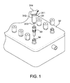
- a conventional semi-permeable column 31 (see Fig. 1 ) generally comprises three parts: an upper cervical section 311, a middle tubular section 312, and a lower tapered section 313.
- the diameter of the upper cervical section 311 is larger than that of the middle tubular section 312.
- Some of the columns include a lid 314.
- the middle tubular section 312 is provided for containing liquid sample, and its internal bottom part includes one or more specific purposed semi-permeable membranes (not shown in the figure).
- Some of the columns have a design of lower tapered sections 313.
- the engagement of the traditional semi-permeable membrane column 31 with a vacuum manifold 32 is in a tight insertion style: the lower tapered section 313 of the liquid semi-permeable membrane column 31 is inserted into a hole 34 of the vacuum manifold 32 directly or via an insertable adaptor column 33.
- the insertable adaptor column 33 is used to avoid direct insertion of the semi-permeable membrane column 31 into the hole 34 of the vacuum manifold 32, as the hole 34 of the vacuum manifold 32 may come in contact with the sample contained in the semi-permeable membrane column, and such can lead to cross contamination amongst different samples.
- the insertable adaptor column 33 can be of a disposable type or can be easily cleaned for repeated use.
- the insertable adaptor column 33 When the insertable adaptor column 33 is used, the lower tapered section 313 of the semi-permeable membrane column 31 is inserted into the insertable adaptor column 33. Then this ensemble is inserted to the hole 34 of the vacuum manifold 32, and forms the following structure from top to bottom: the semi-permeable membrane column 31 - the insertable adaptor column 33 - the vacuum manifold 32.
- Many applications utilize the insertable adaptor column 33, especially experiments which require no cross contamination of the samples, such as using purified nuclear acid for PCR reaction. It is therefore very important that this engagement must be tightly secured to avoid any gas leakage. Often, an operator has to hand-hold the semi-permeable membrane column 31 and the insertable adaptor column 33 to ensure tight engagement.
- the semi-permeable membrane column 31 remains protruding outwardly from the apparatus during operation, and it is inserted into the hole 34 merely at its tip. Thus, it can easily become disengaged from the hole 34 due to any unintentional collision.
- This invention provides an apparatus for processing biological sample, in which a semi-permeable column can be easily placed in the slot of a vacuum manifold.
- an adaptor column can be used to avoid cross-contamination and to prevent the operator coming in direct contact with the liquid sample.
- the semi-permeable column is placed in the adaptor column, and the adaptor column is placed in the slot of the vacuum manifold. In doing so, the operator can easily operate the apparatus, and even repeated perform the operations without causing pain to the operator's fingers.
- the semi-permeable column is loosely received in the slot of the vacuum manifold before air pressure or vacuum is applied. If an adaptor column is introduced between the semi-permeable column and the slot of the vacuum manifold, the gaps existing between the two columns and between the adaptor column and the slot will render that the adaptor column is loosely received in the slot and that the semi-permeable column is loosely received in the adaptor column. Due to the gaps, the semi-permeable column and/or the adaptor column can become unstable during operation, and the accuracy of tests will thus be adversely affected.
- a seal having the effect of sealing and securing the column in position is provided such that when the semi-permeable column in placed in the slot of the vacuum manifold, air-tight condition can be maintained between the column and the slot, and that the semi-permeable column and the adaptor column will be secured in position without shaking and shifting during operation, and the accuracy of test results can be secured.
- the present invention provides an apparatus for processing biological sample, which comprises at least a semi-permeable column and a vacuum manifold, and optionally comprises at least one adaptor column.
- the semi-permeable column is loosely received in the slot of the vacuum manifold, or in the adaptor column, and sealing elements made of resilient material are positioned between the semi-permeable column and the slot of vacuum manifold, or between the adaptor column and the slot of vacuum manifold or between the adaptor column and the semi-permeable column, such that when the semi-permeable column in which contains liquid sample is placed in the slot of the vacuum manifold and vacuum is applied to the vacuum manifold, the liquid sample in the semi-permeable column will be pressurized to pass through the semi-permeable membrane to achieve the desired objective.
- the semi-permeable column comprises an inner portion, a top portion, and a bottom portion.
- the inner portion defines a first receiving space; the top portion has a first opening and a radially protruding first flange; the bottom portion has a protruding first outlet and at least one semi-permeable membrane.
- the adaptor column is used optionally. It is used particularly when the liquid sample is highly contagious and thus direct contact with the liquid sample and cross-contamination should be avoided.
- the adaptor column comprises an inner portion, a top portion, and a bottom portion.
- the inner portion of the adaptor column defines a second receiving space.
- the top portion has a second opening, and a radially protruding second flange.
- the bottom portion has a second outlet.
- the vacuum manifold comprises a base and a lid.
- the interior of the base defines a receiving space.
- the lid comprises at least one slot for receiving at least one semi-permeable column or adaptor column.
- the bottom of the slot has an opening in communication with the receiving space of the base.
- the semi-permeable column is inserted into the slot of the vacuum manifold.
- a sealing element which can be a circular gasket with a central hole, is placed at the bottom of the slot. The central hole allows the protruding outlet of the semi-permeable column to pass through while remaining secured in position to form a sealed contact when the semi-permeable column is inserted into the slot.
- the sealing element is not placed at the bottom of the slot, but instead is placed around the wall of the slot.
- a circular groove is accordingly formed around the wall of the slot of the vacuum manifold to receive a sealing element, which can be an O-ring.
- the sealing element will help to secure the semi-permeable column in position and form a sealed contact with the semi-permeable column when the semi-permeable column is inserted into the slot of the vacuum manifold.
- the semi-permeable column can instead be inserted into the adaptor column.
- the inner diameter of the adaptor column is slightly larger than the outer diameter of the semi-permeable column such that the semi-permeable column can be loosely received in the adaptor column and the first flange of the top portion can rest on the second flange of the adaptor column.
- the second flange is fitted with a sealing element, which is made of a resilient material and in a ring shape.
- Another sealing element is provided between the second outlet at the bottom of the adaptor column and the through hole at the bottom of the slot such that when the air pressure in the first receiving space of the semi-permeable column is higher than that of the reservoir space of the vacuum manifold, the first flange of the semi-permeable column will be in a sealed contact with the second flange of the adaptor column, and the bottom of the adaptor column will be in a sealed contact with the bottom of the slot.
- the sealing element is not positioned at the bottom of the slot, but instead is positioned on the wall of the slot.
- the slot of the vacuum manifold takes a circular groove form on the wall thereof to receive a sealing element, which can be an O-ring.
- Fig. 1 illustrates a conventional apparatus for processing biological sample
- Fig. 2 illustrates a first embodiment of the present invention
- Fig. 3 illustrates a second embodiment of the present invention
- Fig. 4 illustrates a third embodiment of the present invention.
- Fig. 5 illustrates a fourth embodiment of the present invention.
- Fig. 2 illustrates a first embodiment of the present invention, wherein the semi-permeable column 11 is a conventional one.
- Conventional semi-permeable column is generally cylindrical in shape, which comprises an inner portion, a top portion, and a bottom portion.
- the inner portion defines a first receiving space 111, wherein at least one semi-permeable membrane 112 is placed.
- the top portion forms a first opening 116 and a first flange 113 extending radially outwardly from the top portion.
- a first outlet 114 is formed at the bottom portion.
- a sealing element 125 is positioned at the bottom of the slot 143.
- the center of the sealing element 125 has an opening.
- the sealing element 125 will allow the first outlet 114 of the semi-permeable column 11 to be inserted through its central opening. Accordingly, the semi-permeable column 11 can be secured in the slot 143 and the first outlet 114 and the sealing element 125 will form a sealed contact.
- a vacuum is applied to the receiving space 145 of the vacuum manifold 14
- a sealed contact between the slot 143 and the sealing element 125 will be formed and air will be prevented from flowing therebetween.
- the sealed contacts between the first outlet 114 and the sealing element 125 and between the slot 143 and the sealing element 125 ensure that the liquid sample in the semi-permeable column 11 is forced through only the semi-permeable membrane and out of the column under the atmospheric pressure.
- the inventive concept of the present invention is to provide a sealing element such that it not only forms a sealed contact surface but also secures a column in position within the slot of a vacuum manifold.
- a sealing element can be also positioned on the wall of the slot 143 (shown in Fig. 3 ) instead of at the bottom of the slot 143 (shown in Fig. 2 ).
- the wall of the slot 143 is provided with a round groove 147 for receiving a sealing element 125', which can be an O-ring.
- the sealing element 125' can guide to secure it in position, and when a vacuum is applied to the receiving space 145 of the vacuum manifold 14, air would not flow through between the semi-permeable column 11 and the sealing element 125'; this ensures that the sample liquid in the semi-permeable column 11 will only be forced through the semi-permeable membrane 112 and out of the column 11 under the atmospheric pressure.
- an adaptor column 12 can be used and it is inserted between the semi-permeable column 11 and the slot 143, as shown in Fig. 4 , to avoid cross-contamination of the sample liquid.
- the adaptor column 12 generally has the shape of a column, and can be made of any appropriate materials.
- the adaptor column 12 comprises an inner portion, a top portion, and a bottom portion.
- the inner portion defines a second receiving space 121.
- the top portion has a second opening 127 and a second flange 122 extending radially and outwardly from the top portion.
- the flange 122 is fitted a resilient sealing element 13 around the circumference thereof.
- the bottom portion has a second outlet 123.
- the inner diameter of the adaptor column 12 is slightly larger than the outer diameter of the body of the semi-permeable column 11, but smaller than the diameter of the first flange 113 of the semi-permeable column 11 such that the semi-permeable column 11 can be inserted into the adaptor column 12 and be loosely received in the second receiving space 121 of the adaptor column 12 and that the first flange 113 of the top portion of the semi-permeable column 11 can rest on the sealing element 13.
- Fig. 4 shows a third embodiment of the present invention.
- the third embodiment further includes an adaptor column 12.
- a sealing element 13 fits around the circumference of the second flange 122 of the adaptor column 12.
- the sealing element 13 is preferably a resilient ring.
- the adaptor column 12 has a primary function of preventing direct contact between the slot 143 of the vacuum manifold 14 and the semi-permeable column 11 in order to eliminate cross-contamination resulting from repeated use of the semi-permeable column.
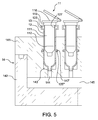
- the sealing element 125" in the third embodiment shown in Fig. 4 does not necessarily need to be positioned at the bottom of the slot 143.
- the slot 143 similar to that of the second embodiment, has a circular groove 147' formed on the wall thereof.
- An O-ring shape sealing element 125"' is fitted to the circular groove 147'.
- the objectives of the present invention are to provide an easily assembled and disassembled apparatus for processing biological samples, to stably secure the columns in position, and to eliminate the disadvantages existing in the conventional apparatus. Since the semi-permeable column or the adaptor column has the advantage of easy insertion into and removal from the slot, the apparatus of the present invention can be used in automatic operation by robot when moving the columns is required.
- the present invention provides an apparatus for securely processing biological sample is used to wash, separate, or purify biological molecules, such as DNAs, RNAs, and proteins.
- the apparatus comprises at least one semi-permeable membrane column, a vacuum manifold, and at least one optional adaptor column.
- the semi-permeable membrane column is loosely received in the slot of the vacuum manifold.
- the adaptor column is used, the semi-permeable membrane column is loosely received in the adaptor column, and the adaptor column is loosely received in the slot of the vacuum manifold.
- the apparatus also comprises sealing elements which are inserted between the column and the slot.
- the apparatus for securely processing biological sample comprises:
Abstract
Description
- The present invention is related to an apparatus for securely processing biological sample.
- Liquid semi-permeable membrane columns (or semi-permeable membrane columns) are commonly used in laboratory for washing, separating, or purifying biological molecules, such as DNA, RNA, and proteins. Semi-permeable membrane columns that are commonly used are mostly cylindrical in shape, wherein the bottom is provided with one or more pieces of semi-permeable membranes of special purposes. The column is infused with liquid, and an adequate force is then applied to the liquid in the column, forcing the liquid out of the column through the semi-permeable membranes.
- Normally, the applied force can be a centrifugal force or air pressure. When centrifugal force is used, the column is usually placed in a liquid collecting tube, and then the liquid is infused in the column. The liquid collecting tube and the column are then placed into a centrifuge. The centrifuge is turned on to spin at high speed to generate a high centrifugal force. The liquid in the column is forced out of the column through the semi-permeable membranes and collected in the liquid collecting tube. The above process is only suitable for a single column. When an operation involving numerous columns is needed, the process would become overly cumbersome as the capacity of a centrifuge is limited. When air pressure is employed as an applied force, numerous semi-permeable membrane columns can be inserted into a vacuum manifold, which has a greater capacity than a centrifuge. By applying a positive or negative air pressure, the liquid is forced out of the columns through the semi-permeable membranes and is collected in the vacuum manifold. The process of using air pressure is more convenient when operating numerous samples or continuous operations.
- A conventional semi-permeable column 31 (see
Fig. 1 ) generally comprises three parts: an uppercervical section 311, a middletubular section 312, and a lowertapered section 313. The diameter of the uppercervical section 311 is larger than that of the middletubular section 312. Some of the columns include alid 314. The middletubular section 312 is provided for containing liquid sample, and its internal bottom part includes one or more specific purposed semi-permeable membranes (not shown in the figure). Some of the columns have a design of lowertapered sections 313. - As shown in
Figure 1 , the engagement of the traditionalsemi-permeable membrane column 31 with avacuum manifold 32 is in a tight insertion style: the lowertapered section 313 of the liquidsemi-permeable membrane column 31 is inserted into ahole 34 of thevacuum manifold 32 directly or via aninsertable adaptor column 33. Theinsertable adaptor column 33 is used to avoid direct insertion of thesemi-permeable membrane column 31 into thehole 34 of thevacuum manifold 32, as thehole 34 of thevacuum manifold 32 may come in contact with the sample contained in the semi-permeable membrane column, and such can lead to cross contamination amongst different samples. Theinsertable adaptor column 33 can be of a disposable type or can be easily cleaned for repeated use. When theinsertable adaptor column 33 is used, the lowertapered section 313 of thesemi-permeable membrane column 31 is inserted into theinsertable adaptor column 33. Then this ensemble is inserted to thehole 34 of thevacuum manifold 32, and forms the following structure from top to bottom: the semi-permeable membrane column 31 - the insertable adaptor column 33 - thevacuum manifold 32. Many applications utilize theinsertable adaptor column 33, especially experiments which require no cross contamination of the samples, such as using purified nuclear acid for PCR reaction. It is therefore very important that this engagement must be tightly secured to avoid any gas leakage. Often, an operator has to hand-hold thesemi-permeable membrane column 31 and theinsertable adaptor column 33 to ensure tight engagement. It is likely that the operator may experience discomfort at the fingers due to this maneuver. On the other hand, as can be better understood by referring toFig. 1 , thesemi-permeable membrane column 31 remains protruding outwardly from the apparatus during operation, and it is inserted into thehole 34 merely at its tip. Thus, it can easily become disengaged from thehole 34 due to any unintentional collision. - To overcome the above disadvantages, the applicant proposed an invention, which has been allowed as
TW 253957 - According to
TW 253957 - In view of this, the applicant makes improvement on
TW 253957 - To achieve the above-mentioned objectives, the present invention provides an apparatus for processing biological sample, which comprises at least a semi-permeable column and a vacuum manifold, and optionally comprises at least one adaptor column. The semi-permeable column is loosely received in the slot of the vacuum manifold, or in the adaptor column, and sealing elements made of resilient material are positioned between the semi-permeable column and the slot of vacuum manifold, or between the adaptor column and the slot of vacuum manifold or between the adaptor column and the semi-permeable column, such that when the semi-permeable column in which contains liquid sample is placed in the slot of the vacuum manifold and vacuum is applied to the vacuum manifold, the liquid sample in the semi-permeable column will be pressurized to pass through the semi-permeable membrane to achieve the desired objective.
- The semi-permeable column comprises an inner portion, a top portion, and a bottom portion. The inner portion defines a first receiving space; the top portion has a first opening and a radially protruding first flange; the bottom portion has a protruding first outlet and at least one semi-permeable membrane.
- The adaptor column is used optionally. It is used particularly when the liquid sample is highly contagious and thus direct contact with the liquid sample and cross-contamination should be avoided. The adaptor column comprises an inner portion, a top portion, and a bottom portion. The inner portion of the adaptor column defines a second receiving space. The top portion has a second opening, and a radially protruding second flange. The bottom portion has a second outlet.
- The vacuum manifold comprises a base and a lid. The interior of the base defines a receiving space. The lid comprises at least one slot for receiving at least one semi-permeable column or adaptor column. The bottom of the slot has an opening in communication with the receiving space of the base.
- During the operation of the apparatus of the present invention, the semi-permeable column is inserted into the slot of the vacuum manifold. A sealing element, which can be a circular gasket with a central hole, is placed at the bottom of the slot. The central hole allows the protruding outlet of the semi-permeable column to pass through while remaining secured in position to form a sealed contact when the semi-permeable column is inserted into the slot.
- In another embodiment, the sealing element is not placed at the bottom of the slot, but instead is placed around the wall of the slot. A circular groove is accordingly formed around the wall of the slot of the vacuum manifold to receive a sealing element, which can be an O-ring. The sealing element will help to secure the semi-permeable column in position and form a sealed contact with the semi-permeable column when the semi-permeable column is inserted into the slot of the vacuum manifold.
- In another embodiment, the semi-permeable column can instead be inserted into the adaptor column. The inner diameter of the adaptor column is slightly larger than the outer diameter of the semi-permeable column such that the semi-permeable column can be loosely received in the adaptor column and the first flange of the top portion can rest on the second flange of the adaptor column. The second flange is fitted with a sealing element, which is made of a resilient material and in a ring shape. Another sealing element is provided between the second outlet at the bottom of the adaptor column and the through hole at the bottom of the slot such that when the air pressure in the first receiving space of the semi-permeable column is higher than that of the reservoir space of the vacuum manifold, the first flange of the semi-permeable column will be in a sealed contact with the second flange of the adaptor column, and the bottom of the adaptor column will be in a sealed contact with the bottom of the slot.
- In another embodiment, the sealing element is not positioned at the bottom of the slot, but instead is positioned on the wall of the slot. In this scenario, the slot of the vacuum manifold takes a circular groove form on the wall thereof to receive a sealing element, which can be an O-ring. When the adaptor column is inserted into the slot of the vacuum manifold, the sealing element will help to secure the adaptor column in position and form a sealed contact therewith.
- To facilitate persons having general knowledge in the art to better understand the technical features of the present invention, and put it into practice, the following descriptions are provided with the accompanied drawings:
-
Fig. 1 illustrates a conventional apparatus for processing biological sample; -
Fig. 2 illustrates a first embodiment of the present invention; -
Fig. 3 illustrates a second embodiment of the present invention; -
Fig. 4 illustrates a third embodiment of the present invention; and -
Fig. 5 illustrates a fourth embodiment of the present invention. -
Fig. 2 illustrates a first embodiment of the present invention, wherein thesemi-permeable column 11 is a conventional one. Conventional semi-permeable column is generally cylindrical in shape, which comprises an inner portion, a top portion, and a bottom portion. The inner portion defines afirst receiving space 111, wherein at least onesemi-permeable membrane 112 is placed. The top portion forms afirst opening 116 and afirst flange 113 extending radially outwardly from the top portion. Afirst outlet 114 is formed at the bottom portion. - As shown in
Fig. 2 , a sealingelement 125 is positioned at the bottom of theslot 143. The center of the sealingelement 125 has an opening. When the semi-permeable column is inserted into theslot 143 of thevacuum manifold 14, the sealingelement 125 will allow thefirst outlet 114 of thesemi-permeable column 11 to be inserted through its central opening. Accordingly, thesemi-permeable column 11 can be secured in theslot 143 and thefirst outlet 114 and the sealingelement 125 will form a sealed contact. When a vacuum is applied to the receivingspace 145 of thevacuum manifold 14, a sealed contact between theslot 143 and the sealingelement 125 will be formed and air will be prevented from flowing therebetween. The sealed contacts between thefirst outlet 114 and the sealingelement 125 and between theslot 143 and the sealingelement 125 ensure that the liquid sample in thesemi-permeable column 11 is forced through only the semi-permeable membrane and out of the column under the atmospheric pressure. - The inventive concept of the present invention is to provide a sealing element such that it not only forms a sealed contact surface but also secures a column in position within the slot of a vacuum manifold. Based on this inventive concept, a sealing element can be also positioned on the wall of the slot 143 (shown in
Fig. 3 ) instead of at the bottom of the slot 143 (shown inFig. 2 ). The wall of theslot 143 is provided with around groove 147 for receiving a sealing element 125', which can be an O-ring. When thesemi-permeable column 11 is inserted into theslot 143, the sealing element 125' can guide to secure it in position, and when a vacuum is applied to the receivingspace 145 of thevacuum manifold 14, air would not flow through between thesemi-permeable column 11 and the sealing element 125'; this ensures that the sample liquid in thesemi-permeable column 11 will only be forced through thesemi-permeable membrane 112 and out of thecolumn 11 under the atmospheric pressure. - When the sample is highly contagious, an
adaptor column 12 can be used and it is inserted between thesemi-permeable column 11 and theslot 143, as shown inFig. 4 , to avoid cross-contamination of the sample liquid. - The
adaptor column 12 generally has the shape of a column, and can be made of any appropriate materials. Theadaptor column 12 comprises an inner portion, a top portion, and a bottom portion. The inner portion defines asecond receiving space 121. The top portion has asecond opening 127 and asecond flange 122 extending radially and outwardly from the top portion. Theflange 122 is fitted aresilient sealing element 13 around the circumference thereof. The bottom portion has asecond outlet 123. The inner diameter of theadaptor column 12 is slightly larger than the outer diameter of the body of thesemi-permeable column 11, but smaller than the diameter of thefirst flange 113 of thesemi-permeable column 11 such that thesemi-permeable column 11 can be inserted into theadaptor column 12 and be loosely received in thesecond receiving space 121 of theadaptor column 12 and that thefirst flange 113 of the top portion of thesemi-permeable column 11 can rest on the sealingelement 13. -
Fig. 4 shows a third embodiment of the present invention. With respect to the first embodiment, the third embodiment further includes anadaptor column 12. A sealingelement 13 fits around the circumference of thesecond flange 122 of theadaptor column 12. The sealingelement 13 is preferably a resilient ring. When a semi-permeable column containing sample liquid is positioned in theadaptor column 12 and theadaptor column 12 is positioned in theslot 143 of thevacuum manifold 14, and when applying a vacuum to thevacuum manifold 14 until the pressure in thefirst receiving space 111 of thesemi-permeable column 11 is greater than that of the receivingspace 145 of thevacuum manifold 14, thefirst flange 113 of thesemi-permeable column 11 and the sealingelement 13 around thesecond flange 122 of theadaptor column 12 will be in a sealed contact. In this scenario, the atmospheric pressure exerting on the sample liquid in thesemi-permeable column 11 will force the sample liquid to flow out of thecolumn 11. Apart from the loosely received and air-sealed features, theadaptor column 12 has a primary function of preventing direct contact between theslot 143 of thevacuum manifold 14 and thesemi-permeable column 11 in order to eliminate cross-contamination resulting from repeated use of the semi-permeable column. - The sealing
element 125" in the third embodiment shown inFig. 4 does not necessarily need to be positioned at the bottom of theslot 143. In the fourth embodiment shown inFig. 5 , theslot 143, similar to that of the second embodiment, has a circular groove 147' formed on the wall thereof. An O-ringshape sealing element 125"' is fitted to the circular groove 147'. When theadaptor column 12 is positioned into theslot 143, the sealingelement 125"' can secure theadaptor column 12 in position. When vacuum is applied to the receivingspace 145 of thevacuum manifold 14, air will not pass through between theadaptor column 12 and the sealingelement 125"' nor between thefirst flange 113 of thesemi-permeable column 11 and the sealingelement 13, and thus the liquid sample in thesemi-permeable column 11 will only be forced through thesemi-permeable membrane 112 and out of the column under the atmospheric pressure.
In summary, the objectives of the present invention are to provide an easily assembled and disassembled apparatus for processing biological samples, to stably secure the columns in position, and to eliminate the disadvantages existing in the conventional apparatus. Since the semi-permeable column or the adaptor column has the advantage of easy insertion into and removal from the slot, the apparatus of the present invention can be used in automatic operation by robot when moving the columns is required.
The present invention provides an apparatus for securely processing biological sample is used to wash, separate, or purify biological molecules, such as DNAs, RNAs, and proteins. The apparatus comprises at least one semi-permeable membrane column, a vacuum manifold, and at least one optional adaptor column. The semi-permeable membrane column is loosely received in the slot of the vacuum manifold. When the adaptor column is used, the semi-permeable membrane column is loosely received in the adaptor column, and the adaptor column is loosely received in the slot of the vacuum manifold. The apparatus also comprises sealing elements which are inserted between the column and the slot. When the semi-permeable membrane column contains liquid sample and vacuum is applied to the vacuum manifold, the liquid in the semi-permeable membrane column can be drawn out of the column through the membrane. When compared with conventional apparatuses, the assembling and disassembling of the apparatus of the present invention are more convenient and the safety of operation can be enhanced.
In a first embodiment (Fig. 2 ) the apparatus for securely processing biological sample, comprises: - at least one semi-permeable column, wherein the inner portion of which defines a first receiving space, the bottom of the first receiving space has at least one semi-permeable membrane, the top portion of the semi-permeable column has a first opening, and the bottom of the semi-permeable column has a first outlet;
- a vacuum manifold, comprising:
- a base, the interior of which defines a receiving space; and
- a lid covering the base, comprising at least one slot, wherein the internal diameter of which is slightly larger than the outer diameter of the semi-permeable column, and the slot forms a through hole at the bottom thereof for communicating with the receiving space of the base;
- at least one sealing element positioning at the bottom of the slot, and each of the sealing elements having an opening at its center, whereby when the semi-permeable column is inserted into the opening at the center of the sealing element, it can be secured in position, and when vacuum is applied to the vacuum manifold, air would not pass through between the first outlet and the sealing element.
- at least one semi-permeable column, wherein the inner portion of which defines a first receiving space, the bottom of the first receiving space has at least one semi-permeable membrane, the top portion of the semi-permeable column has a first opening, and the bottom of the semi-permeable column has a first outlet;
- a vacuum manifold, comprising:
- a base, the interior of which defines a receiving space; and
- a lid covering the base, comprising at least one slot, wherein the internal diameter of which is slightly larger than the outer diameter of the semi-permeable column, and the slot forms a through hole at the bottom thereof for communicating with the receiving space of the base, and further forms at least one annular groove around the wall thereof;
- at least one sealing element in the shape of an O-ring being inserted into the at least one annular groove around the wall of the slot, wherein the inner diameter of the sealing element is slightly smaller than the outer diameter of the semi-permeable column such that when the semi-permeable column is inserted into the slot, it can be secured in position, and when vacuum is applied to the vacuum manifold, air would not pass through between the semi-permeable column and the sealing element.
- at least one semi-permeable column, wherein the inner portion of which defines a first receiving space, the bottom of the first receiving space has at least one semi-permeable membrane, the top portion of the semi-permeable column has a first opening and a flange extending radially and outwardly from the first opening, and the bottom of the semi-permeable column has a first outlet;
- at least one adaptor column, wherein the interior of which defines a second receiving space, the top portion of which has a second opening and a second flange extending radially and outwardly from the second opening, the bottom portion of which has a second outlet protruding downwardly, the diameter of the second receiving space is slightly larger than the outer diameter of the semi-permeable column, the second flange having a second sealing element fitting therearound such that when the semi-permeable is inserted into the adaptor column, the first flange will rest on the second sealing element;
- a vacuum manifold, comprising:
- a base, the interior of which defines a receiving space; and
- a lid covering the base, comprising at least one slot, wherein the internal diameter of which is slightly larger than the outer diameter of the adaptor column, and the slot forms a through hole at the bottom thereof for communicating with the receiving space of the base;
- at least one sealing element positioning at the bottom of the slot, and each of the sealing elements having an opening at its center, whereby when the adaptor column is inserted into the opening at the center of the sealing element, it can be secured in position, and when vacuum is applied to the vacuum manifold, air would not pass through between the second outlet and the sealing element, nor through between the first flange and the second sealing element.
- at least one semi-permeable column, wherein the inner portion of which defines a first receiving space, the bottom of the first receiving space has at least one semi-permeable membrane, the top portion of the semi-permeable column has a first opening and a flange extending radially and outwardly from the first opening, and the bottom of the semi-permeable column has a first outlet;
- at least one adaptor column, wherein the interior of which defines a second receiving space, the top portion of which has a second opening and a second flange extending radially and outwardly from the second opening, the bottom portion of which has a second outlet protruding downwardly, the diameter of the second receiving space is slightly larger than the outer diameter of the semi-permeable column, the second flange having a second sealing element fitting therearound such that when the semi-permeable is inserted into the adaptor column, the first flange will rest on the second sealing element;
- a vacuum manifold, comprising:
- a base, the interior of which defines a receiving space; and
- a lid covering the base, comprising at least one slot, wherein the internal diameter of which is slightly larger than the outer diameter of the adaptor column, and the slot forms a through hole at the bottom thereof for communicating with the receiving space of the base, and further forms at least one annular groove formed on the wall of the slot;
- at least one sealing element in the shape of an O-ring being inserted into the at least one annular groove around the wall of the slot, wherein the inner diameter of the sealing element is slightly smaller than the outer diameter of the adaptor column such that when the adaptor column is inserted into the slot, it can be secured in position, and when vacuum is applied to the vacuum manifold, air would not pass through between the adaptor column and the sealing element and nor through between the first flange and the second sealing element.
- The invention may also be implemented in other specific ways without departing from the spirit and the essence of the invention. Thus, the above-mentioned embodiments should be regarded as explanatory and not restrictive. All changes that remain consistent with the scope of the claims and its equivalents should be deemed as falling within the scope claimed by the invention.
Claims (5)
- An apparatus for securely processing biological sample, comprising:at least one semi-permeable column (11), wherein the inner portion of which defines a first receiving space, the bottom of the first receiving space has at least one semi-permeable membrane, the top portion of the semi-permeable column has a first opening, and the bottom of the semi-permeable column has a first outlet;a vacuum manifold (14), comprising:a base, the interior of which defines a receiving space; anda lid covering the base, comprising at least one slot, wherein the internal diameter of which is slightly larger than the outer diameter of the semi-permeable column, and the slot forms a through hole at the bottom thereof for communicating with the receiving space of the base;at least one sealing element (125; 125', 125", 125") being secured in position such that, when vacuum is applied to the vacuum manifold, air would not pass through between the first outlet and the sealing element.
- An apparatus for securely processing biological sample of claim 1 wherein, the at least one sealing element (125) is positioned at the bottom of the slot, and each of the sealing elements having an opening at its center, whereby when the semi-permeable column is inserted into the opening at the center of the sealing element, it can be secured in position, and when vacuum is applied to the vacuum manifold, air would not pass through between the first outlet and the sealing element.
- An apparatus for securely processing biological sample of claim 1 wherein, the at least one sealing element (125') is in the shape of an O-ring being inserted into the at least one annular groove around the wall of the slot, wherein the inner diameter of the sealing element is slightly smaller than the outer diameter of the semi-permeable column such that when the semi-permeable column is inserted into the slot, it can be secured in position, and when vacuum is applied to the vacuum manifold, air would not pass through between the semi-permeable column and the sealing element.
- An apparatus for securely processing biological sample of claim 1 further comprising:at least one adaptor column (12), wherein the interior of which defines a second receiving space, the top portion of which has a second opening and a second flange extending radially and outwardly from the second opening, the bottom portion of which has a second outlet protruding downwardly, the diameter of the second receiving space is slightly larger than the outer diameter of the semi-permeable column, the second flange having a second sealing element fitting therearound such that when the semi-permeable is inserted into the adaptor column, the first flange will rest on the second sealing element;wherein the lid covering the base has an internal diameter which is slightly larger than the outer diameter of the adaptor column, and the slot forms a through hole at the bottom thereof for communicating with the receiving space of the base; and whereinthe at least one sealing element (125 ") is positioned at the bottom of the slot, and each of the sealing elements having an opening at its center, whereby when the adaptor column is inserted into the opening at the center of the sealing element, it can be secured in position, and when vacuum is applied to the vacuum manifold, air would not pass through between the second outlet and the sealing element, nor through between the first flange and the second sealing element.
- An apparatus for securely processing biological sample of claim 1 further comprising:at least one adaptor column (12), wherein the interior of which defines a second receiving space, the top portion of which has a second opening and a second flange extending radially and outwardly from the second opening, the bottom portion of which has a second outlet protruding downwardly, the diameter of the second receiving space is slightly larger than the outer diameter of the semi-permeable column, the second flange having a second sealing element fitting therearound such that when the semi-permeable is inserted into the adaptor column, the first flange will rest on the second sealing element;wherein te lid covering the base has an internal diameter which is slightly larger than the outer diameter of the adaptor column, and the slot forms a through hole at the bottom thereof for communicating with the receiving space of the base, and further forms at least one annular groove formed on the wall of the slot; and whereinthe at least one sealing element (125"') is in the shape of an O-ring being inserted into the at least one annular groove around the wall of the slot, wherein the inner diameter of the sealing element is slightly smaller than the outer diameter of the adaptor column such that when the adaptor column is inserted into the slot, it can be secured in position, and when vacuum is applied to the vacuum manifold, air would not pass through between the adaptor column and the sealing element and nor through between the first flange and the second sealing element.
Applications Claiming Priority (1)
| Application Number | Priority Date | Filing Date | Title |
|---|---|---|---|
| TW100117468A TWI406712B (en) | 2011-05-18 | 2011-05-18 | Apparatus for securely processing biological sample |
Publications (3)
| Publication Number | Publication Date |
|---|---|
| EP2524728A2 true EP2524728A2 (en) | 2012-11-21 |
| EP2524728A3 EP2524728A3 (en) | 2014-01-15 |
| EP2524728B1 EP2524728B1 (en) | 2024-02-21 |
Family
ID=46146687
Family Applications (1)
| Application Number | Title | Priority Date | Filing Date |
|---|---|---|---|
| EP12168081.3A Active EP2524728B1 (en) | 2011-05-18 | 2012-05-15 | Apparatus for securely processing biological sample |
Country Status (8)
| Country | Link |
|---|---|
| US (1) | US8658105B2 (en) |
| EP (1) | EP2524728B1 (en) |
| JP (1) | JP5365818B2 (en) |
| KR (1) | KR101408599B1 (en) |
| CN (1) | CN102788724B (en) |
| AU (1) | AU2012202681B2 (en) |
| SG (1) | SG185880A1 (en) |
| TW (1) | TWI406712B (en) |
Cited By (1)
| Publication number | Priority date | Publication date | Assignee | Title |
|---|---|---|---|---|
| CN115414701A (en) * | 2022-07-22 | 2022-12-02 | 黄淮学院 | Biomedical-based biological tissue extraction device and method |
Families Citing this family (7)
| Publication number | Priority date | Publication date | Assignee | Title |
|---|---|---|---|---|
| EP2775987A4 (en) | 2011-11-10 | 2015-11-25 | Biofire Diagnostics Llc | Loading vials |
| CN103087903B (en) * | 2013-02-05 | 2015-01-21 | 杭州百迈生物技术有限公司 | Nucleic acid purifying column system and its application in nucleic acid extraction |
| CN103792176A (en) * | 2014-03-04 | 2014-05-14 | 山东省纺织科学研究院 | Sample clamping device for testing medical mask air exchange pressure difference value |
| WO2015152255A1 (en) * | 2014-03-31 | 2015-10-08 | 株式会社ニコン | Supporting device and inspection method |
| CN104251898B (en) * | 2014-10-22 | 2015-07-01 | 威海出入境检验检疫局检验检疫技术中心 | Method for measuring residues of various beta-receptor stimulants by membrane dialysis-liquid chromatography tandem mass spectrometry |
| TWI629104B (en) * | 2017-09-06 | 2018-07-11 | 諾貝爾生物有限公司 | Apparatus for processing biological sample |
| CN110170182B (en) * | 2019-06-12 | 2021-08-10 | 江苏睿玻生物科技有限公司 | Negative pressure purification device and negative pressure purification method |
Family Cites Families (21)
| Publication number | Priority date | Publication date | Assignee | Title |
|---|---|---|---|---|
| AT368389B (en) * | 1981-02-27 | 1982-10-11 | C A Greiner Und Soehne Ges M B | EVACUABLE BLOOD TUBE TUBE CLOSED WITH A GASKET |
| JPS63202372A (en) * | 1987-02-17 | 1988-08-22 | N K Eng Kk | Filtration apparatus for object to be examined |
| US5264184A (en) * | 1991-03-19 | 1993-11-23 | Minnesota Mining And Manufacturing Company | Device and a method for separating liquid samples |
| US5736351A (en) * | 1995-01-09 | 1998-04-07 | New Horizons Diagnostics Corporation | Method for detection of contaminants |
| US5846493A (en) * | 1995-02-14 | 1998-12-08 | Promega Corporation | System for analyzing a substance from a solution following filtering of the substance from the solution |
| US5961925A (en) * | 1997-09-22 | 1999-10-05 | Bristol-Myers Squibb Company | Apparatus for synthesis of multiple organic compounds with pinch valve block |
| JP4245274B2 (en) * | 1998-02-27 | 2009-03-25 | ポール・コーポレーション | Test specimen preparation device and preparation method |
| CN2465801Y (en) * | 2001-04-02 | 2001-12-19 | 武汉市三人工贸有限公司 | Vacuum plastic test tube |
| US7438862B2 (en) * | 2001-08-17 | 2008-10-21 | United Chemical Technologies, Inc. | Apparatus for simultaneous processing of multiple samples |
| FR2830785B1 (en) * | 2001-10-12 | 2004-01-23 | Millipore Sas | METHOD AND INSTRUMENT FOR UNLOCKING A DEVICE COMPRISING TWO AXIALLY LATCHED BODIES |
| US20060177354A1 (en) * | 2005-02-04 | 2006-08-10 | Taigen Bioscience Corporation | Apparatus for processing biological sample |
| TWI253957B (en) * | 2005-02-04 | 2006-05-01 | Taigen Bioscience Corp | Apparatus for processing biochemical sample |
| CN201001985Y (en) * | 2006-11-30 | 2008-01-09 | 中国石油化工股份有限公司 | Filtering funnel |
| US20090011506A1 (en) * | 2007-07-02 | 2009-01-08 | Industrial Technology Research Institute | Apparatus and process for washing tissue and/or cell |
| CN100553751C (en) * | 2007-08-13 | 2009-10-28 | 南京九思高科技有限公司 | A kind of hollow fiber ceramic membrane element and assembly thereof |
| WO2009106760A2 (en) * | 2008-01-09 | 2009-09-03 | Metagenex | Device and method for isolating and cultivating live cells on a filter or extracting the genetic material thereof |
| EP2305789A4 (en) * | 2008-06-27 | 2013-12-25 | Hitachi Plant Technologies Ltd | Cartridge of microbial cell-capturing carrier, carrier treating device and method for counting microbial cells |
| CN201326841Y (en) * | 2008-11-21 | 2009-10-14 | 董阿能 | Connecting and sealing device |
| US20110313143A1 (en) * | 2008-12-15 | 2011-12-22 | Life Technologies Corporation | Nucleic acid purification apparatus and method |
| CN201464357U (en) * | 2009-07-29 | 2010-05-12 | 北京利达科信环境安全技术有限公司 | Sealed flow cell with double-layer glass tube structure |
| CN201651641U (en) * | 2010-03-20 | 2010-11-24 | 永高股份有限公司 | Elastic sealing ring type pipe joint |
-
2011
- 2011-05-18 TW TW100117468A patent/TWI406712B/en active
-
2012
- 2012-05-02 SG SG2012032439A patent/SG185880A1/en unknown
- 2012-05-02 JP JP2012105431A patent/JP5365818B2/en active Active
- 2012-05-07 CN CN201210138972.8A patent/CN102788724B/en active Active
- 2012-05-08 AU AU2012202681A patent/AU2012202681B2/en not_active Ceased
- 2012-05-15 US US13/472,191 patent/US8658105B2/en active Active
- 2012-05-15 EP EP12168081.3A patent/EP2524728B1/en active Active
- 2012-05-16 KR KR1020120051916A patent/KR101408599B1/en active IP Right Grant
Non-Patent Citations (1)
| Title |
|---|
| None |
Cited By (2)
| Publication number | Priority date | Publication date | Assignee | Title |
|---|---|---|---|---|
| CN115414701A (en) * | 2022-07-22 | 2022-12-02 | 黄淮学院 | Biomedical-based biological tissue extraction device and method |
| CN115414701B (en) * | 2022-07-22 | 2023-08-08 | 黄淮学院 | Biomedical-based biological tissue extraction device and method |
Also Published As
| Publication number | Publication date |
|---|---|
| AU2012202681B2 (en) | 2014-02-13 |
| KR20120129787A (en) | 2012-11-28 |
| SG185880A1 (en) | 2012-12-28 |
| CN102788724A (en) | 2012-11-21 |
| JP5365818B2 (en) | 2013-12-11 |
| JP2012254078A (en) | 2012-12-27 |
| TWI406712B (en) | 2013-09-01 |
| US20120294778A1 (en) | 2012-11-22 |
| CN102788724B (en) | 2015-10-28 |
| US8658105B2 (en) | 2014-02-25 |
| TW201247323A (en) | 2012-12-01 |
| EP2524728A3 (en) | 2014-01-15 |
| EP2524728B1 (en) | 2024-02-21 |
| KR101408599B1 (en) | 2014-06-17 |
| AU2012202681A1 (en) | 2012-12-06 |
Similar Documents
| Publication | Publication Date | Title |
|---|---|---|
| US8658105B2 (en) | Apparatus for securely processing biological sample | |
| EP2574326B1 (en) | Filter vial having a tubular piston a retainer cup and a filter | |
| US9897520B2 (en) | All-in-one sample preparation device and method | |
| JP5432891B2 (en) | Duplex container and dispensing method | |
| JP2023153792A (en) | isolation tube | |
| JP4459172B2 (en) | Apparatus for processing biological samples | |
| US20140023567A1 (en) | Filter vial | |
| US8937174B2 (en) | Method and device for the automated processing of a sample | |
| JP2005121655A (en) | Filtration and extraction device and method of using the same | |
| CN1815166B (en) | Apparatus for processing biological sample | |
| US11680233B2 (en) | Nucleic acid extraction and purification device and biochemical molecule extraction and purification device | |
| JPH08278234A (en) | Container for decreasing contamination when liquid is processed | |
| US20120087847A1 (en) | Filtering tube and microtube for the preparation and purification of small sample volumes | |
| US10882008B2 (en) | Apparatus for processing biological sample | |
| US20110079556A1 (en) | Separation of solids from liquids by filtration and centrifugation | |
| CN211553477U (en) | Sample processing cavity |
Legal Events
| Date | Code | Title | Description |
|---|---|---|---|
| PUAI | Public reference made under article 153(3) epc to a published international application that has entered the european phase |
Free format text: ORIGINAL CODE: 0009012 |
|
| AK | Designated contracting states |
Kind code of ref document: A2 Designated state(s): AL AT BE BG CH CY CZ DE DK EE ES FI FR GB GR HR HU IE IS IT LI LT LU LV MC MK MT NL NO PL PT RO RS SE SI SK SM TR |
|
| AX | Request for extension of the european patent |
Extension state: BA ME |
|
| PUAL | Search report despatched |
Free format text: ORIGINAL CODE: 0009013 |
|
| AK | Designated contracting states |
Kind code of ref document: A3 Designated state(s): AL AT BE BG CH CY CZ DE DK EE ES FI FR GB GR HR HU IE IS IT LI LT LU LV MC MK MT NL NO PL PT RO RS SE SI SK SM TR |
|
| AX | Request for extension of the european patent |
Extension state: BA ME |
|
| RIC1 | Information provided on ipc code assigned before grant |
Ipc: B01L 3/00 20060101AFI20131211BHEP |
|
| 17P | Request for examination filed |
Effective date: 20140709 |
|
| RBV | Designated contracting states (corrected) |
Designated state(s): AL AT BE BG CH CY CZ DE DK EE ES FI FR GB GR HR HU IE IS IT LI LT LU LV MC MK MT NL NO PL PT RO RS SE SI SK SM TR |
|
| STAA | Information on the status of an ep patent application or granted ep patent |
Free format text: STATUS: EXAMINATION IS IN PROGRESS |
|
| 17Q | First examination report despatched |
Effective date: 20171106 |
|
| STAA | Information on the status of an ep patent application or granted ep patent |
Free format text: STATUS: EXAMINATION IS IN PROGRESS |
|
| STAA | Information on the status of an ep patent application or granted ep patent |
Free format text: STATUS: EXAMINATION IS IN PROGRESS |
|
| GRAP | Despatch of communication of intention to grant a patent |
Free format text: ORIGINAL CODE: EPIDOSNIGR1 |
|
| STAA | Information on the status of an ep patent application or granted ep patent |
Free format text: STATUS: GRANT OF PATENT IS INTENDED |
|
| INTG | Intention to grant announced |
Effective date: 20231109 |
|
| RAP1 | Party data changed (applicant data changed or rights of an application transferred) |
Owner name: LABTURBO BIOTECH CORPORATION |
|
| GRAS | Grant fee paid |
Free format text: ORIGINAL CODE: EPIDOSNIGR3 |
|
| GRAA | (expected) grant |
Free format text: ORIGINAL CODE: 0009210 |
|
| STAA | Information on the status of an ep patent application or granted ep patent |
Free format text: STATUS: THE PATENT HAS BEEN GRANTED |
|
| AK | Designated contracting states |
Kind code of ref document: B1 Designated state(s): AL AT BE BG CH CY CZ DE DK EE ES FI FR GB GR HR HU IE IS IT LI LT LU LV MC MK MT NL NO PL PT RO RS SE SI SK SM TR |
|
| REG | Reference to a national code |
Ref country code: GB Ref legal event code: FG4D |
|
| REG | Reference to a national code |
Ref country code: CH Ref legal event code: EP |
|
| REG | Reference to a national code |
Ref country code: DE Ref legal event code: R096 Ref document number: 602012080558 Country of ref document: DE |
|
| REG | Reference to a national code |
Ref country code: IE Ref legal event code: FG4D |
|
| U01 | Request for unitary effect filed |
Effective date: 20240226 |
|
| U07 | Unitary effect registered |
Designated state(s): AT BE BG DE DK EE FI FR IT LT LU LV MT NL PT SE SI Effective date: 20240305 |