EP2523866B1 - Container - Google Patents
Container Download PDFInfo
- Publication number
- EP2523866B1 EP2523866B1 EP11700245.1A EP11700245A EP2523866B1 EP 2523866 B1 EP2523866 B1 EP 2523866B1 EP 11700245 A EP11700245 A EP 11700245A EP 2523866 B1 EP2523866 B1 EP 2523866B1
- Authority
- EP
- European Patent Office
- Prior art keywords
- lid
- skirt
- section
- bending
- directed ridge
- Prior art date
- Legal status (The legal status is an assumption and is not a legal conclusion. Google has not performed a legal analysis and makes no representation as to the accuracy of the status listed.)
- Not-in-force
Links
- 238000005452 bending Methods 0.000 claims description 75
- 239000000463 material Substances 0.000 claims description 9
- 230000000694 effects Effects 0.000 description 18
- 238000007789 sealing Methods 0.000 description 8
- 238000004519 manufacturing process Methods 0.000 description 2
- 230000001010 compromised effect Effects 0.000 description 1
- 239000013013 elastic material Substances 0.000 description 1
- 239000012530 fluid Substances 0.000 description 1
- 238000002347 injection Methods 0.000 description 1
- 239000007924 injection Substances 0.000 description 1
- 238000001746 injection moulding Methods 0.000 description 1
- 239000012528 membrane Substances 0.000 description 1
- 230000002093 peripheral effect Effects 0.000 description 1
- 230000003014 reinforcing effect Effects 0.000 description 1
- 238000000926 separation method Methods 0.000 description 1
- 230000003313 weakening effect Effects 0.000 description 1
Images




Classifications
-
- B—PERFORMING OPERATIONS; TRANSPORTING
- B65—CONVEYING; PACKING; STORING; HANDLING THIN OR FILAMENTARY MATERIAL
- B65D—CONTAINERS FOR STORAGE OR TRANSPORT OF ARTICLES OR MATERIALS, e.g. BAGS, BARRELS, BOTTLES, BOXES, CANS, CARTONS, CRATES, DRUMS, JARS, TANKS, HOPPERS, FORWARDING CONTAINERS; ACCESSORIES, CLOSURES, OR FITTINGS THEREFOR; PACKAGING ELEMENTS; PACKAGES
- B65D43/00—Lids or covers for rigid or semi-rigid containers
- B65D43/02—Removable lids or covers
- B65D43/0202—Removable lids or covers without integral tamper element
- B65D43/0204—Removable lids or covers without integral tamper element secured by snapping over beads or projections
- B65D43/0212—Removable lids or covers without integral tamper element secured by snapping over beads or projections only on the outside, or a part turned to the outside, of the mouth
-
- B—PERFORMING OPERATIONS; TRANSPORTING
- B65—CONVEYING; PACKING; STORING; HANDLING THIN OR FILAMENTARY MATERIAL
- B65D—CONTAINERS FOR STORAGE OR TRANSPORT OF ARTICLES OR MATERIALS, e.g. BAGS, BARRELS, BOTTLES, BOXES, CANS, CARTONS, CRATES, DRUMS, JARS, TANKS, HOPPERS, FORWARDING CONTAINERS; ACCESSORIES, CLOSURES, OR FITTINGS THEREFOR; PACKAGING ELEMENTS; PACKAGES
- B65D43/00—Lids or covers for rigid or semi-rigid containers
- B65D43/02—Removable lids or covers
-
- B—PERFORMING OPERATIONS; TRANSPORTING
- B65—CONVEYING; PACKING; STORING; HANDLING THIN OR FILAMENTARY MATERIAL
- B65D—CONTAINERS FOR STORAGE OR TRANSPORT OF ARTICLES OR MATERIALS, e.g. BAGS, BARRELS, BOTTLES, BOXES, CANS, CARTONS, CRATES, DRUMS, JARS, TANKS, HOPPERS, FORWARDING CONTAINERS; ACCESSORIES, CLOSURES, OR FITTINGS THEREFOR; PACKAGING ELEMENTS; PACKAGES
- B65D43/00—Lids or covers for rigid or semi-rigid containers
- B65D43/02—Removable lids or covers
- B65D43/0235—Removable lids or covers with integral tamper element
- B65D43/0237—Removable lids or covers with integral tamper element secured by snapping over beads or projections before removal of the tamper element
- B65D43/0256—Removable lids or covers with integral tamper element secured by snapping over beads or projections before removal of the tamper element only on the outside, or a part turned to the outside, of the mouth of the container
-
- B—PERFORMING OPERATIONS; TRANSPORTING
- B65—CONVEYING; PACKING; STORING; HANDLING THIN OR FILAMENTARY MATERIAL
- B65D—CONTAINERS FOR STORAGE OR TRANSPORT OF ARTICLES OR MATERIALS, e.g. BAGS, BARRELS, BOTTLES, BOXES, CANS, CARTONS, CRATES, DRUMS, JARS, TANKS, HOPPERS, FORWARDING CONTAINERS; ACCESSORIES, CLOSURES, OR FITTINGS THEREFOR; PACKAGING ELEMENTS; PACKAGES
- B65D2543/00—Lids or covers essentially for box-like containers
- B65D2543/00009—Details of lids or covers for rigid or semi-rigid containers
- B65D2543/00018—Overall construction of the lid
- B65D2543/00064—Shape of the outer periphery
- B65D2543/0012—Shape of the outer periphery having straight sides, e.g. with curved corners
- B65D2543/00175—Shape of the outer periphery having straight sides, e.g. with curved corners four straight sides, e.g. trapezium or diamond
- B65D2543/00194—Shape of the outer periphery having straight sides, e.g. with curved corners four straight sides, e.g. trapezium or diamond square or rectangular
-
- B—PERFORMING OPERATIONS; TRANSPORTING
- B65—CONVEYING; PACKING; STORING; HANDLING THIN OR FILAMENTARY MATERIAL
- B65D—CONTAINERS FOR STORAGE OR TRANSPORT OF ARTICLES OR MATERIALS, e.g. BAGS, BARRELS, BOTTLES, BOXES, CANS, CARTONS, CRATES, DRUMS, JARS, TANKS, HOPPERS, FORWARDING CONTAINERS; ACCESSORIES, CLOSURES, OR FITTINGS THEREFOR; PACKAGING ELEMENTS; PACKAGES
- B65D2543/00—Lids or covers essentially for box-like containers
- B65D2543/00009—Details of lids or covers for rigid or semi-rigid containers
- B65D2543/00018—Overall construction of the lid
- B65D2543/00259—Materials used
- B65D2543/00296—Plastic
-
- B—PERFORMING OPERATIONS; TRANSPORTING
- B65—CONVEYING; PACKING; STORING; HANDLING THIN OR FILAMENTARY MATERIAL
- B65D—CONTAINERS FOR STORAGE OR TRANSPORT OF ARTICLES OR MATERIALS, e.g. BAGS, BARRELS, BOTTLES, BOXES, CANS, CARTONS, CRATES, DRUMS, JARS, TANKS, HOPPERS, FORWARDING CONTAINERS; ACCESSORIES, CLOSURES, OR FITTINGS THEREFOR; PACKAGING ELEMENTS; PACKAGES
- B65D2543/00—Lids or covers essentially for box-like containers
- B65D2543/00009—Details of lids or covers for rigid or semi-rigid containers
- B65D2543/00444—Contact between the container and the lid
- B65D2543/00592—Snapping means
- B65D2543/00601—Snapping means on the container
- B65D2543/00611—Profiles
- B65D2543/00629—Massive bead
-
- B—PERFORMING OPERATIONS; TRANSPORTING
- B65—CONVEYING; PACKING; STORING; HANDLING THIN OR FILAMENTARY MATERIAL
- B65D—CONTAINERS FOR STORAGE OR TRANSPORT OF ARTICLES OR MATERIALS, e.g. BAGS, BARRELS, BOTTLES, BOXES, CANS, CARTONS, CRATES, DRUMS, JARS, TANKS, HOPPERS, FORWARDING CONTAINERS; ACCESSORIES, CLOSURES, OR FITTINGS THEREFOR; PACKAGING ELEMENTS; PACKAGES
- B65D2543/00—Lids or covers essentially for box-like containers
- B65D2543/00009—Details of lids or covers for rigid or semi-rigid containers
- B65D2543/00444—Contact between the container and the lid
- B65D2543/00592—Snapping means
- B65D2543/00712—Snapping means on the lid
- B65D2543/00722—Profiles
- B65D2543/0074—Massive bead
-
- B—PERFORMING OPERATIONS; TRANSPORTING
- B65—CONVEYING; PACKING; STORING; HANDLING THIN OR FILAMENTARY MATERIAL
- B65D—CONTAINERS FOR STORAGE OR TRANSPORT OF ARTICLES OR MATERIALS, e.g. BAGS, BARRELS, BOTTLES, BOXES, CANS, CARTONS, CRATES, DRUMS, JARS, TANKS, HOPPERS, FORWARDING CONTAINERS; ACCESSORIES, CLOSURES, OR FITTINGS THEREFOR; PACKAGING ELEMENTS; PACKAGES
- B65D2543/00—Lids or covers essentially for box-like containers
- B65D2543/00009—Details of lids or covers for rigid or semi-rigid containers
- B65D2543/00824—Means for facilitating removing of the closure
- B65D2543/00833—Integral tabs, tongues, handles or similar
- B65D2543/00842—Integral tabs, tongues, handles or similar outside of the lid
Definitions
- the present invention relates to a container, according to the preamble of claim 1, comprising a number of side walls meeting at corners, a bottom, a top opening and a detachable lid covering the top opening, the top opening being provided with a peripherally extending outward directed ridge, the lid being provided with a peripherally extending downward bent engagement portion having an inward directed ridge adapted to grip under the outward directed ridge of the top opening, the lid further being provided with a skirt extending below the engagement portion from the inward directed ridge thereof, the outward directed ridge of the top opening and the corresponding inward directed ridge of the lid having curved corner sections at the corners at which the side walls of the container meet, said curved corner sections connecting side sections of the respective ridges, where at least one of the curved corner sections of the inward directed ridge of the lid is provided with a bendable skirt section being adapted to be bent to an outward directed position in such a way that a central part of the at least one curved corner section of the inward directed ridge
- EP 1 681 242 B1 discloses a container of this type, having four walls meeting at rounded corners.
- a recess is formed in the skirt of the container wall near a corner, so that a pair of fingers may be inserted into the recess and thereby press upward on the skirt of the lid:
- a considerable force may be necessary to disengage the inward directed ridge of the lid from the outward directed ridge of the top opening. Pressing on the lower edge of the thin wall of the skirt may be inconvenient for the user.
- a container comprising a number of side walls meeting at corners, a bottom, a top opening and a detachable lid covering the top opening, the top opening being provided with a peripherally extending outwardly directed ridge, the lid being provided with a peripherally extending downwardly bent engagement portion having an inwardly directed ridge adapted to grip under the outward directed ridge of the top opening, the lid further being provided with a skirt extending below the engagement portion from the inward directed ridge thereof, the outward directed ridge of the top opening and the corresponding inward directed ridge of the lid having curved corner sections at the corners at which the side walls of the container meet, said curved corner sections connecting side sections of the respective ridges, where at least one of the curved corner sections of the inward directed ridge of the lid is provided with a bendable skirt section being adapted to be bent to an outward directed position in such a way that a central part of
- the inward directed ridge of the lid and/or the outward directed ridge of the top opening with a smaller cross-section or a smaller protrusion in the radial direction in the area of the corner to be opened than along the rest of the peripheral extension of the lid and top opening.
- the cross-section or the protrusion in the radial direction of the ridges cannot be too small, and consequently the lid may still be somewhat difficult to open.
- the object of the present invention is to facilitate the opening of the container without compromising the sealing effect between the lid and the top opening.
- the bendable skirt section is separated from the remaining part of the skirt by means of at least two grooves formed in the outside surface of the skirt and extending downward from an area at the bending line to the lower edge of the skirt, said grooves reducing the wall thickness of the skirt so that the skirt may break along the grooves in order to bend the bendable skirt section to its outward directed position.
- a pair of fingers may press on the lower side of bendable skirt section, thereby bending it outward and consequently weakening the engagement between the corresponding ridges, so that the necessary opening force is reduced and opening thereby facilitated.
- the engagement between the corresponding ridges is not weakened, and therefore the sealing effect is not compromised.
- the cross-section and/or the radial protrusion of the corresponding ridges may additionally be reduced in the corner to be opened in order to further facilitate opening of the container. It is also possible to form the corresponding ridges of another material than the rest of the lid or of the container; for instance, one or both of the ridges or even a larger part of the corner of the lid and/or of the top opening of the container may be formed of a softer and/or more elastic material incorporated by co-injection.
- the ridges may be formed with unreduced cross-section and/or radial protrusion along the entire periphery of the container in order to improve the sealing effect before opening the container. Due to the levering effect according to the invention, opening of the lid may still be possible and/or facilitated without changing the ridge form at the corner or corners to be opened.
- the bendable skirt section is prepared for bending about a bending line along which the material of the lid is weakened or about which the material of the lid is pre-bent.
- the bending line may be predetermined at the design stage of the container, and it may be ensured that the bendable skirt section is bent along a line providing optimized levering effect in order to effectively lift the inward directed ridge of the lid away from the outward directed ridge of the top opening. Furthermore, bending of the bendable skirt section may be facilitated.
- a bending line is formed in a bending section connecting the peripherally extending downward bent engagement portion and the skirt, and the bending section has an outside extending obliquely downward and outward, the outside thereby forming an angle with both the peripherally extending downward bent engagement portion and the skirt.
- the bending line extends below mutually contacting faces of the outward directed ridge of the top opening and the corresponding inward directed ridge of the lid, respectively. Thereby, it may be ensured that the inward directed ridge of the lid will not break during bending, and consequently the sealing effect after re-closing of the lid may be good.
- a protrusion is formed next to a bending line and on the outside of the engagement portion or on the outside of the bendable skirt section, and in that said protrusion is adapted to be pinched between the bendable skirt section and the engagement portion when bending the bendable skirt section to its outward directed position. Thereby, the protrusion may enhance the levering effect in order to even more effectively lever a central part of the at least one curved corner section of the inward directed ridge of the lid away from the outward directed ridge of the top opening.
- At least a part of the bendable skirt section may be separated from the remaining part of the skirt by means of two spaced elastic elements, such as parts of the skirt having a wall thickness thinner than the remaining part of the skirt or parts of the skirt having a bellows-type configuration.
- the sealing effect of the lid after re-closing of the container may be improved in that the bendable skirt section may flex elastically back at least approximately to its initial position, thereby ensuring good engagement between the inward directed ridge of the lid and the outward directed ridge of the top opening after closing.
- spaced elastic or expandable elements may split at least part of the inward directed ridge of the lid at either side of the bendable skirt section. Thereby, disengagement between the inward directed ridge of the lid and the outward directed ridge of the top opening may be facilitated during opening of the container, thereby facilitating opening. This may be possible without compromising the sealing effect of the lid, because the spaced elastic or expandable elements may seal the split area of the inward directed ridge of the lid against fluid leakage.
- the bendable skirt section is separated from the remaining part of the skirt by means of two cuts or pre-cuts extending downward from an area below the inward directed ridge of the lid. This may be an embodiment easy to manufacture. In the case of pre-cuts, a tamper evident container may be provided.
- the bendable skirt section is separated from the remaining part of the skirt by means of at least two grooves formed in the outside surface of the skirt and extending downward from an area at the bending line to the lower edge of the skirt, said grooves reducing the wall thickness of the skirt so that the skirt may break along the grooves in order to bend the bendable skirt section to its outward directed position.
- This may be an embodiment easy to manufacture.
- a tamper evident container may be provided.
- the bendable skirt section is reinforced against bending along a line extending in its longitudinal direction, preferably by means of ribs extending at right angles to its longitudinal direction.
- the levering effect of the bendable skirt section may be improved in order to even more effectively lever the inward directed ridge of the lid away from the outward directed ridge of the top opening.
- the bendable skirt section is reinforced against bending along a line extending in its longitudinal direction by means of mutually spaced ribs extending at right angles to its longitudinal direction, said ribs having upper ends adapted to abut the outside of the engagement portion when bending the bendable skirt section to its outward directed position.
- the abutment of the protrusions in the form of the upper ends of the ribs may enhance the levering effect in order to even more effectively lever a central part of the at least one curved corner section of the inward directed ridge of the lid away from the outward directed ridge of the top opening.
- the curved corner section 11 of the inward directed ridge 8 of the lid 5 is provided with a bendable skirt section 12 being adapted to be bent to an outward directed position as it is seen in the figure and, for instance, approximately directed as indicated by the line 12' in Fig. 1 .
- the container 1 is further provided with a skirt section 24 extending downwards at the outside of the upper edge of the side walls 2.
- a grip opening not shown in Fig. 1 may be provided in the skirt section 24 below the bendable skirt section 12, so that a finger may be inserted into the grip opening in order to grip below the edge of the bendable skirt section 12 to bend it to its outward directed position.
- a grip opening may be provided in the bendable skirt section 12 itself or any other suitable gripping means, such as a protrusion, may be provided on the bendable skirt section 12 in order to facilitate gripping.
- One or more of the curved corner sections 11 of the inward directed ridge 8 of the lid 5 may be provided with such a bendable skirt section 12.
- two diagonally opposed corner sections 11 may be provided with a bendable skirt section 12, such as at the lower, right corner 3 and at the upper, left corner 3 of the container 1 as shown in Fig. 2 .
- This may be advantageous, for instance, in an embodiment as shown in Figs. 7 and 8 , wherein the container is substantially rectangular and is provided with diagonally opposed grip openings 23 in a skirt section 24 extending at the outside of the upper edge of the side walls 2. Due to this configuration, the lid 5 may be mounted on the opening 4 of the container in any of two possible positions, thereby facilitating the assembly. In any of these positions, a bendable skirt section 12 will be placed above a corresponding grip opening 23 in the skirt section 24.
- the bendable skirt section 12 may just as well be adapted to be bent to an outward directed position that is angled relative to the horizontal, for instance so that the outer free end of the bendable skirt section 12 is directed obliquely upwards.
- the outer free end of the bendable skirt section 12 may, in the bent out position of the bendable skirt section 12, be directed obliquely downwards.
- the arrow 13 indicates the bending direction in which the bendable skirt section 12 is bent in such a way that a central part of the curved corner section 11 of the inward directed ridge 8 of the lid 5 is levered away from the outward directed ridge 6 of the top opening 4 and that engagement between the corresponding ridges 6, 8 thereby is weakened in an area at said central part.
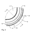
- the curved corner section 11 of the inward directed ridge 8 of the lid 5 is shown in cross-section in Fig. 1 and is not visible in Fig. 3 ; however, it is noted that the curved corner section 11 of the inward directed ridge 8 extends between the marks 14 and 15 in Fig. 3 and follows the rounded lines that are seen on the top side of the lid and that extend between these marks 14, 15.
- the above-mentioned central part of the curved corner section 11 of the inward directed ridge 8 of the lid 5 may, for instance, extend about 1/3 or about 1/2 of the length of the curved corner section 11.
- the expression inward, when relating to the ridges 6, 8 or anything else along the periphery of the container 1 means directed against a central vertical axis through the container when the container is placed with its bottom on a horizontal surface.
- Outward relates to the opposite direction, which is away from said vertical axis.
- all directions mentioned in this application relate to the container 1 when it is placed with its bottom on a horizontal surface.
- the bendable skirt section is prepared for bending about a bending line along which the material of the lid is weakened or about which the material of the lid is pre-bent or along which the material of the lid in any other suitable way is prepared or adapted to facilitate bending.
- a bending line 16 is formed in a bending section 17 connecting the peripherally extending downward bent engagement portion 7 and the skirt 9.
- the bending section 17 has an outside extending obliquely downward and outward, the outside thereby forming an angle with both the peripherally extending downward bent engagement portion 7 and the skirt 9.
- the bending line 16 is indicated in the area of the angle formed between the outside of the bending section 17 and the downward bent engagement portion 7; however, depending on the exact configuration of the form of the lid 5, the bending line 16 may also be located further downwards of the bending section 17.
- the bending line 16 may follow a path of different heights along the length of the curved corner section 11 of the inward directed ridge 8.
- the bending line 16 may be positioned slightly higher at the central part of the curved corner sections 11 than at end parts of the curved corner section 11.
- the bending line 16 may be positioned slightly lower at the central part of the curved corner section 11 than at end parts of the curved corner section 11.
- the bending line 16 extends below mutually contacting faces of the outward directed ridge 6 of the top opening 4 and the corresponding inward directed ridge 8 of the lid 5, respectively. Thereby, it may be ensured that the inward directed ridge 8 is not broken during the bending operation.
- the bending line 16 is formed in a bending section 17 located well below the inward directed ridge 8 of the lid 5.
- the bending line 16 is formed in a bending section 17 located at the upper part of the inward directed ridge 8 of the lid 5.
- the bendable skirt section 12 is separated from the remaining part of the skirt 9 by means of two cuts 18 or pre-cuts extending downward from an area below the inward directed ridge 8 of the lid 5.
- one or more further cuts separating the bendable skirt section 12 into two or more parts may be provided.
- the cuts 18 may extend further upward and split at least part of the inward directed ridge 8 of the lid 5 at either side of the bendable skirt section 12. However, in that case it may be preferred to cover the cut at least through the inward directed ridge 8 by means of elastic or expandable elements in order to ensure the sealing effect of the lid before and preferably also after opening and re-closing. It is noted that in such an example, the bending line 16 may in part or entirely extend above the angle between the engagement portion 7 and the bending section 17; in fact, it may in part or entirely extend at a level with or even above the inward directed ridge 8.
- At least a part of the bendable skirt section 12 may be separated from the remaining part of the skirt 9 by means of two, not shown spaced elastic elements, such as parts of the skirt 9 having a wall thickness thinner than the remaining part of the skirt or parts of the skirt having a bellows-type configuration. Thereby, the bendable skirt section 12 may return automatically to its initial position after opening of the lid.
- Such spaced elastic or expandable elements would split at least part of the inward directed ridge 8 of the lid at either side of the bendable skirt section 12.
- the bendable skirt section 12 is reinforced against bending along a line extending in its longitudinal direction, for instance, by means of reinforcing ribs or other suitable protrusions or the like. Thereby, the above-mentioned levering effect of the bendable skirt section 12 may be enhanced. In the embodiments shown in Figs. 4 to 12 , this is done by means of ribs (21) extending at right angles to the longitudinal direction of the bendable skirt section 12. Thereby, it may be ensured that the bendable skirt section 12 does not bend itself; on the contrary, it is rather bent in relation to the engagement portion 7 about a bending line 16.
- the bendable skirt section 12 is separated from the remaining part of the skirt 9 by means of two grooves 22 formed in the outside surface of the skirt 9 and extending downward from an area at the bending line 16 to the lower edge of the skirt 9.
- the grooves 22 reduce the wall thickness of the skirt 9 from a normal thickness T to a reduced thickness t, so that the skirt may break along the grooves 22 in order to bend the bendable skirt section 12 to its outward directed position 12'.
- the grooves 22 are seen to have a substantially triangular cross-sectional form.
- the bendable skirt section 12 is separated into two separate bendable skirt sections 12a, 12b by means of a groove 22' similar to the grooves 22 separating the bendable skirt section 12 from the remaining part of the skirt 9.
- the provision of this additional groove 22' may further facilitate the bending up of the bendable skirt section 12 in that the separation of the bendable skirt section 12 into two separate bendable skirt sections 12a, 12b may reduce tensions in the bendable skirt section 12 during bending, especially in the longitudinal direction of, and near the lower edge of, the bendable skirt section 12.
- the bendable skirt section 12 may further be separated into more separate bendable skirt sections by means of more supplementary grooves 22'.
- the grooves 22, 22' extend up to the obliquely, downward extending outside of the bending section 17 connecting the peripherally extending downward bent engagement portion 7 and the skirt 9.
- the grooves 22, 22' providing the reduced wall thickness t also extend up to the upper part of the inward directed ridge 8; however, because of the thickness of the inward directed ridge 8, the inward directed ridge 8 may not break when the skirt is broken along the grooves 22 in order to bend the bendable skirt section 12 to its outward directed position 12'.
- the bendable skirt section 12 when the bendable skirt section 12 is bent to its outward directed position 12', the part of the inward directed ridge 8 located above the grooves 22 may twist about its longitudinal axis in order to enable a central part of the curved corner section 11 of the inward directed ridge 8 of the lid 5 to be levered away from the outward directed ridge 6 of the top opening 4, whereby engagement between the corresponding ridges 6, 8 is weakened in an area at said central part.
- the bendable skirt section 12 is reinforced against bending along a line extending in its longitudinal direction by means of mutually spaced ribs 21 extending at right angles to its longitudinal direction, whereby the levering effect may be enhanced.
- the ribs 21 have upper ends 25 adapted to abut the outside of the engagement portion 7 when bending the bendable skirt section 12 to its outward directed position 12'. It is noted that, in this embodiment, the upper ends 25 of the ribs 21, in the not bent position of the bendable skirt section 12, are positioned above the bending section 17 and extend obliquely upwards in radial outward direction. During the bending operation, at a point in time, the upper ends 25 of the ribs 21 will abut the outside of the engagement portion 7, whereby the levering effect may be further enhanced.
- the configuration of the top opening 4, the peripherally extending outward directed ridge 6, the lid 5, the peripherally extending downward bent engagement portion 7, the inward directed ridge 8 and the skirt 9 corresponds to a large extend to that of the embodiment shown in Fig. 1 .
- the bendable skirt section 12 is reinforced against bending by means of mutually spaced ribs 21 extending at right angles to its longitudinal direction in a similar way to the embodiment shown in Figs. 4 and 5 .
- the upper ends 25 of the ribs 21, in the not bent position of the bendable skirt section 12, are positioned above the bending section 17 and extend obliquely downwards in radial outward direction.
- the bending line 16 due to the ribs 21, is formed somewhat above the bending section 17 that is located well below the inward directed ridge 8 of the lid 5.
- the bending line 16 is, though, formed below the inward directed ridge 8.
- the bendable skirt section 12 may be bent to a position even further than the position 12' indicated in Fig. 6 , in which position the bendable skirt section 12 may extend obliquely upwards in radially outwards direction, before the upper ends 25 of the ribs 21 abut the outside of the engagement portion 7.
- This may be advantageous in this embodiment, wherein the bending section 17, as mentioned above, is located well below the inward directed ridge 8 of the lid 5, and wherein the bending line 16 is located below the inward directed ridge 8.
- the grooves 22, 22' are formed in the outside surface of the skirt 9; however, they may just as well be formed in the inside surface of the skirt 9. In the latter case, the grooves 22, 22' may preferably extend no further up than to the lower area of the inward directed ridge 8 of the lid 5 in order not to break through the ridge.
- the substantially straight side walls 2 bend slightly in outward direction. They may, for instance, curve with a radius of 2 metres, but just as well with a radius of 30 centimetres or even less, whereas the curved corner section 10 of the outward directed ridge 6 and the curved corner section 11 of the inward directed ridge 8 may curve with a radius of about 3 centimetres. However, the radii of the curved corner sections 10, 11 may be even smaller, such as about 1 to 2 centimetres. These radii may however just as well be larger than 3 centimetres.
- the container may have any suitable number of side walls 2.
Landscapes
- Engineering & Computer Science (AREA)
- Mechanical Engineering (AREA)
- Closures For Containers (AREA)
- Containers Having Bodies Formed In One Piece (AREA)
Description
- The present invention relates to a container, according to the preamble of
claim 1, comprising a number of side walls meeting at corners, a bottom, a top opening and a detachable lid covering the top opening, the top opening being provided with a peripherally extending outward directed ridge, the lid being provided with a peripherally extending downward bent engagement portion having an inward directed ridge adapted to grip under the outward directed ridge of the top opening, the lid further being provided with a skirt extending below the engagement portion from the inward directed ridge thereof, the outward directed ridge of the top opening and the corresponding inward directed ridge of the lid having curved corner sections at the corners at which the side walls of the container meet, said curved corner sections connecting side sections of the respective ridges, where at least one of the curved corner sections of the inward directed ridge of the lid is provided with a bendable skirt section being adapted to be bent to an outward directed position in such a way that a central part of the at least one curved corner section of the inward directed ridge of the lid is levered away from the outward directed ridge of the top opening and that engagement between the corresponding ridges thereby is weakened in an area at said central part. -
EP 1 681 242 B1 (Superfos -
DE 201 12 433 U1 andEP 0 110 859 A1 each accord with the preamble ofclaim 1 and disclose a container comprising a number of side walls meeting at corners, a bottom, a top opening and a detachable lid covering the top opening, the top opening being provided with a peripherally extending outwardly directed ridge, the lid being provided with a peripherally extending downwardly bent engagement portion having an inwardly directed ridge adapted to grip under the outward directed ridge of the top opening, the lid further being provided with a skirt extending below the engagement portion from the inward directed ridge thereof, the outward directed ridge of the top opening and the corresponding inward directed ridge of the lid having curved corner sections at the corners at which the side walls of the container meet, said curved corner sections connecting side sections of the respective ridges, where at least one of the curved corner sections of the inward directed ridge of the lid is provided with a bendable skirt section being adapted to be bent to an outward directed position in such a way that a central part of the at least one curved corner section of the inward directed ridge of the lid is levered away from the outward directed ridge of the top opening and that engagement between the corresponding ridges thereby is weakened in an area at said central part. - In order to overcome the force necessary to open the container, it is known to form the inward directed ridge of the lid and/or the outward directed ridge of the top opening with a smaller cross-section or a smaller protrusion in the radial direction in the area of the corner to be opened than along the rest of the peripheral extension of the lid and top opening. However, as a proper sealing effect of the lid has to be maintained, the cross-section or the protrusion in the radial direction of the ridges cannot be too small, and consequently the lid may still be somewhat difficult to open. There are also known containers having a lid with a relatively thicker skirt in the corner to be opened in order not to hurt the fingers.
- The object of the present invention is to facilitate the opening of the container without compromising the sealing effect between the lid and the top opening.
- In view of this object, in that the bendable skirt section is separated from the remaining part of the skirt by means of at least two grooves formed in the outside surface of the skirt and extending downward from an area at the bending line to the lower edge of the skirt, said grooves reducing the wall thickness of the skirt so that the skirt may break along the grooves in order to bend the bendable skirt section to its outward directed position.
- Thereby, in order to open the container, a pair of fingers may press on the lower side of bendable skirt section, thereby bending it outward and consequently weakening the engagement between the corresponding ridges, so that the necessary opening force is reduced and opening thereby facilitated. Before opening, the engagement between the corresponding ridges is not weakened, and therefore the sealing effect is not compromised.
- The cross-section and/or the radial protrusion of the corresponding ridges may additionally be reduced in the corner to be opened in order to further facilitate opening of the container. It is also possible to form the corresponding ridges of another material than the rest of the lid or of the container; for instance, one or both of the ridges or even a larger part of the corner of the lid and/or of the top opening of the container may be formed of a softer and/or more elastic material incorporated by co-injection.
- Alternatively, the ridges may be formed with unreduced cross-section and/or radial protrusion along the entire periphery of the container in order to improve the sealing effect before opening the container. Due to the levering effect according to the invention, opening of the lid may still be possible and/or facilitated without changing the ridge form at the corner or corners to be opened.
- In an embodiment, the bendable skirt section is prepared for bending about a bending line along which the material of the lid is weakened or about which the material of the lid is pre-bent. Thereby, the bending line may be predetermined at the design stage of the container, and it may be ensured that the bendable skirt section is bent along a line providing optimized levering effect in order to effectively lift the inward directed ridge of the lid away from the outward directed ridge of the top opening. Furthermore, bending of the bendable skirt section may be facilitated.
- In an embodiment, a bending line is formed in a bending section connecting the peripherally extending downward bent engagement portion and the skirt, and the bending section has an outside extending obliquely downward and outward, the outside thereby forming an angle with both the peripherally extending downward bent engagement portion and the skirt. Thereby, bending of the bendable skirt section may start along the angled connection between the engagement portion and the bending section and further continue by bending over the entire bending section. In this way, the position of bending may be well controlled.
- In an embodiment, the bending line extends below mutually contacting faces of the outward directed ridge of the top opening and the corresponding inward directed ridge of the lid, respectively. Thereby, it may be ensured that the inward directed ridge of the lid will not break during bending, and consequently the sealing effect after re-closing of the lid may be good.
In an embodiment, a protrusion is formed next to a bending line and on the outside of the engagement portion or on the outside of the bendable skirt section, and in that said protrusion is adapted to be pinched between the bendable skirt section and the engagement portion when bending the bendable skirt section to its outward directed position. Thereby, the protrusion may enhance the levering effect in order to even more effectively lever a central part of the at least one curved corner section of the inward directed ridge of the lid away from the outward directed ridge of the top opening. - Though not forming a part of the invention, at least a part of the bendable skirt section may be separated from the remaining part of the skirt by means of two spaced elastic elements, such as parts of the skirt having a wall thickness thinner than the remaining part of the skirt or parts of the skirt having a bellows-type configuration. Thereby, the sealing effect of the lid after re-closing of the container may be improved in that the bendable skirt section may flex elastically back at least approximately to its initial position, thereby ensuring good engagement between the inward directed ridge of the lid and the outward directed ridge of the top opening after closing.
- Though not forming a part of the invention, spaced elastic or expandable elements may split at least part of the inward directed ridge of the lid at either side of the bendable skirt section. Thereby, disengagement between the inward directed ridge of the lid and the outward directed ridge of the top opening may be facilitated during opening of the container, thereby facilitating opening. This may be possible without compromising the sealing effect of the lid, because the spaced elastic or expandable elements may seal the split area of the inward directed ridge of the lid against fluid leakage.
- In an embodiment, the bendable skirt section is separated from the remaining part of the skirt by means of two cuts or pre-cuts extending downward from an area below the inward directed ridge of the lid. This may be an embodiment easy to manufacture. In the case of pre-cuts, a tamper evident container may be provided.
- In an embodiment, the bendable skirt section is separated from the remaining part of the skirt by means of at least two grooves formed in the outside surface of the skirt and extending downward from an area at the bending line to the lower edge of the skirt, said grooves reducing the wall thickness of the skirt so that the skirt may break along the grooves in order to bend the bendable skirt section to its outward directed position. This may be an embodiment easy to manufacture. In the case of pre-cuts, a tamper evident container may be provided.
- In an embodiment, the bendable skirt section is reinforced against bending along a line extending in its longitudinal direction, preferably by means of ribs extending at right angles to its longitudinal direction. Thereby, the levering effect of the bendable skirt section may be improved in order to even more effectively lever the inward directed ridge of the lid away from the outward directed ridge of the top opening.
- In an embodiment, the bendable skirt section is reinforced against bending along a line extending in its longitudinal direction by means of mutually spaced ribs extending at right angles to its longitudinal direction, said ribs having upper ends adapted to abut the outside of the engagement portion when bending the bendable skirt section to its outward directed position. Thereby, the abutment of the protrusions in the form of the upper ends of the ribs may enhance the levering effect in order to even more effectively lever a central part of the at least one curved corner section of the inward directed ridge of the lid away from the outward directed ridge of the top opening.
- The invention will now be explained in more detail below by means of examples of embodiments with reference to the very schematic drawing, in which
-
Fig. 1 is a cross-section through a corner of the container according to the invention along the line indicated inFig. 3 ; -
Fig. 2 is a top view of the container; -
Fig. 3 is a detail of the container as Indicated inFig. 2 ; -
Fig. 4 is a cross-sectional view corresponding to that ofFig. 1 of another embodiment of the container according to the invention; -
Fig. 5 is a perspective view of the outside of the corner of the lid of the container illustrated inFig. 4 ; -
Fig. 6 is a cross-sectional view corresponding to that ofFig. 1 of yet another embodiment of the container according to the invention; -
Fig. 7 and 8 are different perspective views of the embodiment of the container shown inFig. 6 , whereby a bendable skirt section of the lid is in its original position and in its bent out position, respectively; -
Fig. 9 and 10 are perspective views of the lid of the embodiment of the container shown inFig. 6 , whereby a bendable skirt section of the lid is in its original position and in its bent out position, respectively; and -
Fig 11 and 12 are different perspective views of a detail showing a bendable skirt section of the lid shown inFigs. 9 and 10 , whereby the bendable skirt section is in its original position and in its bent out position, respectively. -
Fig. 2 shows a top view of acontainer 1 according to the invention. Thecontainer 1 has fourside walls 2 meeting atcorners 3, a not shown bottom, a top opening 4 and adetachable lid 5 covering the top opening, see alsoFig. 1 . Thecontainer 1 and thelid 5 comprised by the container are preferably produced in plastic material by injection moulding. Thetop opening 4 is provided with a peripherally extending outward directedridge 6, and thelid 5 is provided with a peripherally extending downwardbent engagement portion 7 having an inward directedridge 8 adapted to grip under the outward directedridge 6 of thetop opening 4. In the embodiment shown, amembrane 20 of the lid is lowered in relation to the downwardbent engagement portion 7 by means of awall 19. Thelid 5 is further provided with askirt 9 extending below theengagement portion 7 from the inward directedridge 8 thereof. The outward directedridge 6 of thetop opening 4 and the corresponding inward directedridge 8 of thelid 5 havecurved corner sections corners 3 at which the sides of thecontainer 1 meet, saidcurved corner sections respective ridges curved corner section 10 of the outward directedridge 6 and thecurved corner section 11 of the inward directedridge 8 are visible in cross-section inFig. 1 . - At the lower,
right corner 3 of thecontainer 1 as shown inFig. 2 , thecurved corner section 11 of the inward directedridge 8 of thelid 5 is provided with abendable skirt section 12 being adapted to be bent to an outward directed position as it is seen in the figure and, for instance, approximately directed as indicated by the line 12' inFig. 1 . As it may be seen inFig. 1 , thecontainer 1 is further provided with askirt section 24 extending downwards at the outside of the upper edge of theside walls 2. A grip opening not shown inFig. 1 may be provided in theskirt section 24 below thebendable skirt section 12, so that a finger may be inserted into the grip opening in order to grip below the edge of thebendable skirt section 12 to bend it to its outward directed position. Alternatively, a grip opening may be provided in thebendable skirt section 12 itself or any other suitable gripping means, such as a protrusion, may be provided on thebendable skirt section 12 in order to facilitate gripping. - One or more of the
curved corner sections 11 of the inward directedridge 8 of thelid 5 may be provided with such abendable skirt section 12. Especially, two diagonallyopposed corner sections 11 may be provided with abendable skirt section 12, such as at the lower,right corner 3 and at the upper,left corner 3 of thecontainer 1 as shown inFig. 2 . This may be advantageous, for instance, in an embodiment as shown inFigs. 7 and 8 , wherein the container is substantially rectangular and is provided with diagonally opposedgrip openings 23 in askirt section 24 extending at the outside of the upper edge of theside walls 2. Due to this configuration, thelid 5 may be mounted on theopening 4 of the container in any of two possible positions, thereby facilitating the assembly. In any of these positions, abendable skirt section 12 will be placed above a corresponding grip opening 23 in theskirt section 24. - Although the line 12' in
Fig. 1 is shown as an approximately horizontal line, thebendable skirt section 12 may just as well be adapted to be bent to an outward directed position that is angled relative to the horizontal, for instance so that the outer free end of thebendable skirt section 12 is directed obliquely upwards. Alternatively, the outer free end of thebendable skirt section 12 may, in the bent out position of thebendable skirt section 12, be directed obliquely downwards. Thearrow 13 indicates the bending direction in which thebendable skirt section 12 is bent in such a way that a central part of thecurved corner section 11 of the inward directedridge 8 of thelid 5 is levered away from the outward directedridge 6 of thetop opening 4 and that engagement between the correspondingridges curved corner section 11 of the inward directedridge 8 of thelid 5 is shown in cross-section inFig. 1 and is not visible inFig. 3 ; however, it is noted that thecurved corner section 11 of the inward directedridge 8 extends between themarks Fig. 3 and follows the rounded lines that are seen on the top side of the lid and that extend between thesemarks curved corner section 11 of the inward directedridge 8 of thelid 5 may, for instance, extend about 1/3 or about 1/2 of the length of thecurved corner section 11. - In the context of this invention, the expression inward, when relating to the
ridges container 1 means directed against a central vertical axis through the container when the container is placed with its bottom on a horizontal surface. Outward relates to the opposite direction, which is away from said vertical axis. In fact, all directions mentioned in this application relate to thecontainer 1 when it is placed with its bottom on a horizontal surface. - Advantageously, the bendable skirt section is prepared for bending about a bending line along which the material of the lid is weakened or about which the material of the lid is pre-bent or along which the material of the lid in any other suitable way is prepared or adapted to facilitate bending.
- However, in the embodiment shown in
Fig. 1 , abending line 16 is formed in abending section 17 connecting the peripherally extending downwardbent engagement portion 7 and theskirt 9. The bendingsection 17 has an outside extending obliquely downward and outward, the outside thereby forming an angle with both the peripherally extending downwardbent engagement portion 7 and theskirt 9. InFig. 1 , the bendingline 16 is indicated in the area of the angle formed between the outside of thebending section 17 and the downwardbent engagement portion 7; however, depending on the exact configuration of the form of thelid 5, the bendingline 16 may also be located further downwards of thebending section 17. In fact, in order to optimize the levering effect of thebendable skirt section 12, the bendingline 16 may follow a path of different heights along the length of thecurved corner section 11 of the inward directedridge 8. For instance, the bendingline 16 may be positioned slightly higher at the central part of thecurved corner sections 11 than at end parts of thecurved corner section 11. For instance, in another embodiment, the bendingline 16 may be positioned slightly lower at the central part of thecurved corner section 11 than at end parts of thecurved corner section 11. - It may be preferred that the bending
line 16 extends below mutually contacting faces of the outward directedridge 6 of thetop opening 4 and the corresponding inward directedridge 8 of thelid 5, respectively. Thereby, it may be ensured that the inward directedridge 8 is not broken during the bending operation. - In the embodiment shown in
Fig. 1 , it is seen that the bendingline 16 is formed in abending section 17 located well below the inward directedridge 8 of thelid 5. In the embodiment shown inFig. 4 , it is seen that the bendingline 16 is formed in abending section 17 located at the upper part of the inward directedridge 8 of thelid 5. - In the embodiment shown in
Fig. 3 , it is seen that that thebendable skirt section 12 is separated from the remaining part of theskirt 9 by means of twocuts 18 or pre-cuts extending downward from an area below the inward directedridge 8 of thelid 5. In further embodiments, one or more further cuts separating thebendable skirt section 12 into two or more parts may be provided. - Though not forming a part of the invention, the
cuts 18 may extend further upward and split at least part of the inward directedridge 8 of thelid 5 at either side of thebendable skirt section 12. However, in that case it may be preferred to cover the cut at least through the inward directedridge 8 by means of elastic or expandable elements in order to ensure the sealing effect of the lid before and preferably also after opening and re-closing. It is noted that in such an example, the bendingline 16 may in part or entirely extend above the angle between theengagement portion 7 and thebending section 17; in fact, it may in part or entirely extend at a level with or even above the inward directedridge 8. - Though not forming a part of the invention, at least a part of the
bendable skirt section 12 may be separated from the remaining part of theskirt 9 by means of two, not shown spaced elastic elements, such as parts of theskirt 9 having a wall thickness thinner than the remaining part of the skirt or parts of the skirt having a bellows-type configuration. Thereby, thebendable skirt section 12 may return automatically to its initial position after opening of the lid. - Such spaced elastic or expandable elements would split at least part of the inward directed
ridge 8 of the lid at either side of thebendable skirt section 12. - In an embodiment, the
bendable skirt section 12 is reinforced against bending along a line extending in its longitudinal direction, for instance, by means of reinforcing ribs or other suitable protrusions or the like. Thereby, the above-mentioned levering effect of thebendable skirt section 12 may be enhanced. In the embodiments shown inFigs. 4 to 12 , this is done by means of ribs (21) extending at right angles to the longitudinal direction of thebendable skirt section 12. Thereby, it may be ensured that thebendable skirt section 12 does not bend itself; on the contrary, it is rather bent in relation to theengagement portion 7 about abending line 16. - In the embodiment shown in
Figs. 4 and5 , thebendable skirt section 12 is separated from the remaining part of theskirt 9 by means of twogrooves 22 formed in the outside surface of theskirt 9 and extending downward from an area at thebending line 16 to the lower edge of theskirt 9. Thegrooves 22 reduce the wall thickness of theskirt 9 from a normal thickness T to a reduced thickness t, so that the skirt may break along thegrooves 22 in order to bend thebendable skirt section 12 to its outward directed position 12'. In the embodiment shown, thegrooves 22 are seen to have a substantially triangular cross-sectional form. Furthermore, in the embodiment shown, thebendable skirt section 12 is separated into two separatebendable skirt sections grooves 22 separating thebendable skirt section 12 from the remaining part of theskirt 9. The provision of this additional groove 22' may further facilitate the bending up of thebendable skirt section 12 in that the separation of thebendable skirt section 12 into two separatebendable skirt sections bendable skirt section 12 during bending, especially in the longitudinal direction of, and near the lower edge of, thebendable skirt section 12. In other embodiments, thebendable skirt section 12 may further be separated into more separate bendable skirt sections by means of more supplementary grooves 22'. - It is noted that, in the embodiment shown in
Figs. 4 and5 , thegrooves 22, 22' extend up to the obliquely, downward extending outside of thebending section 17 connecting the peripherally extending downwardbent engagement portion 7 and theskirt 9. As thebending section 17 in this embodiment is located at the upper part of the inward directedridge 8 of thelid 5, thegrooves 22, 22' providing the reduced wall thickness t also extend up to the upper part of the inward directedridge 8; however, because of the thickness of the inward directedridge 8, the inward directedridge 8 may not break when the skirt is broken along thegrooves 22 in order to bend thebendable skirt section 12 to its outward directed position 12'. Therefore, when thebendable skirt section 12 is bent to its outward directed position 12', the part of the inward directedridge 8 located above thegrooves 22 may twist about its longitudinal axis in order to enable a central part of thecurved corner section 11 of the inward directedridge 8 of thelid 5 to be levered away from the outward directedridge 6 of thetop opening 4, whereby engagement between the correspondingridges Figs. 4 and5 , it is noted, as explained above, that thebendable skirt section 12 is reinforced against bending along a line extending in its longitudinal direction by means of mutually spacedribs 21 extending at right angles to its longitudinal direction, whereby the levering effect may be enhanced. Theribs 21 have upper ends 25 adapted to abut the outside of theengagement portion 7 when bending thebendable skirt section 12 to its outward directed position 12'. It is noted that, in this embodiment, the upper ends 25 of theribs 21, in the not bent position of thebendable skirt section 12, are positioned above the bendingsection 17 and extend obliquely upwards in radial outward direction. During the bending operation, at a point in time, the upper ends 25 of theribs 21 will abut the outside of theengagement portion 7, whereby the levering effect may be further enhanced. - In the embodiment shown in
Figs. 6 to 12 , the configuration of thetop opening 4, the peripherally extending outward directedridge 6, thelid 5, the peripherally extending downwardbent engagement portion 7, the inward directedridge 8 and theskirt 9 corresponds to a large extend to that of the embodiment shown inFig. 1 . However, thebendable skirt section 12 is reinforced against bending by means of mutually spacedribs 21 extending at right angles to its longitudinal direction in a similar way to the embodiment shown inFigs. 4 and5 . However, as it may be seen inFig. 6 , in this embodiment, the upper ends 25 of theribs 21, in the not bent position of thebendable skirt section 12, are positioned above the bendingsection 17 and extend obliquely downwards in radial outward direction. Further, it is noted that the bendingline 16, due to theribs 21, is formed somewhat above the bendingsection 17 that is located well below the inward directedridge 8 of thelid 5. The bendingline 16 is, though, formed below the inward directedridge 8. During the bending operation, at a point in time, the upper ends 25 of theribs 21 will abut the outside of theengagement portion 7, whereby the levering effect may be further enhanced. Due to the, in radial outward direction, obliquely downwards extent of the upper ends 25 of theribs 21, thebendable skirt section 12 may be bent to a position even further than the position 12' indicated inFig. 6 , in which position thebendable skirt section 12 may extend obliquely upwards in radially outwards direction, before the upper ends 25 of theribs 21 abut the outside of theengagement portion 7. This may be advantageous in this embodiment, wherein thebending section 17, as mentioned above, is located well below the inward directedridge 8 of thelid 5, and wherein thebending line 16 is located below the inward directedridge 8. - It is noted that in the embodiment shown in
Figs. 4 and5 as well as in the embodiment shown inFigs. 6 to 12 , thegrooves 22, 22' are formed in the outside surface of theskirt 9; however, they may just as well be formed in the inside surface of theskirt 9. In the latter case, thegrooves 22, 22' may preferably extend no further up than to the lower area of the inward directedridge 8 of thelid 5 in order not to break through the ridge. - In
Fig. 2 it is seen that, in the shown embodiment, the substantiallystraight side walls 2 bend slightly in outward direction. They may, for instance, curve with a radius of 2 metres, but just as well with a radius of 30 centimetres or even less, whereas thecurved corner section 10 of the outward directedridge 6 and thecurved corner section 11 of the inward directedridge 8 may curve with a radius of about 3 centimetres. However, the radii of thecurved corner sections side walls 2.
Claims (6)
- A container (1) comprising a number of side walls (2) meeting at corners (3), a bottom, a top opening (4) and a detachable lid (5) covering the top opening, the top opening being provided with a peripherally extending outwardly directed ridge (6), the lid (5) being provided with a peripherally extending downwardly bent engagement portion (7) having an inwardly directed ridge (8) adapted to grip under the outward directed ridge (6) of the top opening, the lid (5) further being provided with a skirt (9) extending below the engagement portion (7) from the inward directed ridge (8) thereof, the outward directed ridge (6) of the top opening (4) and the corresponding inward directed ridge (8) of the lid (5) having curved corner sections (10, 11) at the corners (3) at which the side walls (2) of the container meet, said curved corner sections (10, 11) connecting side sections of the respective ridges (6, 8), where at least one of the curved corner sections (11) of the inward directed ridge (8) of the lid (5) is provided with a bendable skirt section (12) being adapted to be bent to an outward directed position (12') in such a way that a central part of the at least one curved corner section (11) of the inward directed ridge (8) of the lid is levered away from the outward directed ridge (6) of the top opening (4) and that engagement between the corresponding ridges (6, 8) thereby is weakened in an area at said central part, characterized in that the bendable skirt section (12) is separated from the remaining part of the skirt (9) by means of two cuts (18) or pre-cuts extending downward from an area below the inward directed ridge (8) of the lid or by means of at least two grooves (22) formed in the outside surface of the skirt (9) and extending downward from an area at the bending line (16) to the lower edge of the skirt (9), said grooves (22) reducing the wall thickness of the skirt (9) so that the skirt is breakable along the grooves (22) in order to bend the bendable skirt section (12) to its outward directed position (12'), the bending line (16) extending below mutually contacting faces of the outward directed ridge (6) of the top opening (4) and the corresponding inward directed ridge (8) of the lid (5), respectively.
- A container according to claim 1, characterized in that the bendable skirt section (12) is prepared for bending about a bending line (16) along which the material of the lid (5) is weakened or about which the material of the lid is pre-bent.
- A container according to claim 1 or 2, characterized in that a bending line (16) is formed in a bending section (17) connecting the peripherally extending downward bent engagement portion (7) and the skirt (9), and in that the bending section (17) has an outside extending obliquely downward and outward, the outside thereby forming an angle with both the peripherally extending downward bent engagement portion and the skirt.
- A container according to any one of the preceding claims, characterized in that a protrusion is formed next to the bending line (16) and on the outside of the engagement portion (7) or on the outside of the bendable skirt section (12), and in that said protrusion is adapted to be pinched between the bendable skirt section (12) and the engagement portion (7) when bending the bendable skirt section (12) to its outward directed position (12').
- A container according to any one of the preceding claims, characterized in that the bendable skirt section (12) is reinforced against bending along a line extending in its longitudinal direction, preferably by means of ribs (21) extending at right angles to its longitudinal direction.
- A container according to any one of the preceding claims, characterized in that the bendable skirt section (12) is reinforced against bending along a line extending in its longitudinal direction by means of mutually spaced ribs (21) extending at right angles to its longitudinal direction, said ribs (21) having upper ends (25) adapted to abut the outside of the engagement portion (7) when bending the bendable skirt section (12) to its outward directed position (12').
Priority Applications (1)
| Application Number | Priority Date | Filing Date | Title |
|---|---|---|---|
| PL11700245T PL2523866T3 (en) | 2010-01-11 | 2011-01-07 | Container |
Applications Claiming Priority (3)
| Application Number | Priority Date | Filing Date | Title |
|---|---|---|---|
| DKPA201070010 | 2010-01-11 | ||
| DKPA201070066 | 2010-02-24 | ||
| PCT/EP2011/050152 WO2011083139A1 (en) | 2010-01-11 | 2011-01-07 | Container |
Publications (2)
| Publication Number | Publication Date |
|---|---|
| EP2523866A1 EP2523866A1 (en) | 2012-11-21 |
| EP2523866B1 true EP2523866B1 (en) | 2014-03-19 |
Family
ID=43639883
Family Applications (1)
| Application Number | Title | Priority Date | Filing Date |
|---|---|---|---|
| EP11700245.1A Not-in-force EP2523866B1 (en) | 2010-01-11 | 2011-01-07 | Container |
Country Status (15)
| Country | Link |
|---|---|
| US (2) | US20130098914A1 (en) |
| EP (1) | EP2523866B1 (en) |
| AU (1) | AU2011204619B2 (en) |
| CA (1) | CA2786808C (en) |
| DK (1) | DK2523866T3 (en) |
| ES (1) | ES2472946T3 (en) |
| MA (1) | MA33990B1 (en) |
| MX (1) | MX2012008013A (en) |
| NZ (1) | NZ601237A (en) |
| PL (1) | PL2523866T3 (en) |
| PT (1) | PT2523866E (en) |
| RU (1) | RU2531898C2 (en) |
| TN (1) | TN2012000354A1 (en) |
| WO (1) | WO2011083139A1 (en) |
| ZA (1) | ZA201205618B (en) |
Cited By (1)
| Publication number | Priority date | Publication date | Assignee | Title |
|---|---|---|---|---|
| US12037163B2 (en) | 2018-04-16 | 2024-07-16 | Berry Superfos Randers A/S | Injection moulded packaging with a container having a folded upper rim |
Families Citing this family (22)
| Publication number | Priority date | Publication date | Assignee | Title |
|---|---|---|---|---|
| EP2523866B1 (en) * | 2010-01-11 | 2014-03-19 | Superfos A/S | Container |
| JP6216636B2 (en) * | 2013-12-19 | 2017-10-18 | シロウマサイエンス株式会社 | container |
| KR200480372Y1 (en) * | 2014-09-02 | 2016-05-16 | 이민규 | multistage-food container |
| PL3215433T3 (en) * | 2014-11-07 | 2019-01-31 | Rpc Superfos A/S | Lid lever for container |
| US9834340B2 (en) | 2015-03-02 | 2017-12-05 | Dart Container Corporation | Tamper evident and resistant container |
| US9994369B2 (en) | 2015-03-02 | 2018-06-12 | Dart Container Corporation | Tamper evident and resistant container |
| EP3214007B1 (en) * | 2016-03-02 | 2019-01-02 | Dart Container Corporation | Tamper evident and resistant container |
| AU2016418327A1 (en) * | 2016-08-11 | 2019-03-21 | Kem Weichoreak Kang | An improved plastic container body and container closure and carry handle grip / container leverage opening tool assembly |
| US10279962B2 (en) * | 2017-03-21 | 2019-05-07 | Display Pack, Inc. | Tamper-evident thermoformed packaging |
| USD831961S1 (en) * | 2017-12-05 | 2018-10-30 | Iscar, Ltd. | Container |
| FR3081449B1 (en) * | 2018-05-28 | 2021-04-30 | Roquette Freres | PACKAGING INCLUDING A PLASTIC CONTAINER WITH NO CONSTANT STACKING |
| USD878054S1 (en) * | 2018-09-28 | 2020-03-17 | Creative Plastic Concepts, Llc | Sealing lid |
| FR3088059B1 (en) | 2018-11-06 | 2020-10-16 | Roquette Freres | OPENING INDICATOR PACKAGING |
| US11905074B2 (en) | 2018-11-06 | 2024-02-20 | Roquette Freres | Packaging with tamper-evident seal |
| USD919429S1 (en) * | 2019-05-13 | 2021-05-18 | Michael Hoerauf Maschinenfabrik Gmbh Und Co. Kg | Container |
| JP1650458S (en) * | 2019-05-31 | 2020-01-20 | ||
| USD988129S1 (en) * | 2019-09-16 | 2023-06-06 | Seung Il Corporation | Spray cap for aerosol container |
| FR3106337B1 (en) | 2020-01-17 | 2021-12-17 | Roquette Freres | Packaging |
| USD947020S1 (en) * | 2020-02-11 | 2022-03-29 | Ipl Plastics Inc. | Container |
| JP1689983S (en) * | 2021-02-24 | 2021-07-12 | ||
| DE202021101125U1 (en) * | 2021-03-05 | 2022-06-08 | Groku Kunststoffe Gmbh | Container with a removable lid |
| FR3130769A1 (en) * | 2021-12-17 | 2023-06-23 | Cm Finances | Lid for closing a container |
Family Cites Families (83)
| Publication number | Priority date | Publication date | Assignee | Title |
|---|---|---|---|---|
| US1026282A (en) * | 1911-08-21 | 1912-05-14 | American Bottle Cap Company | Cap or closure for milk and other bottles. |
| US2614727A (en) * | 1949-03-11 | 1952-10-21 | William H Robinson | Container and closure therefor |
| US2984382A (en) * | 1959-05-14 | 1961-05-16 | Jr Ivan P Florsheim | Container with flexible cover |
| US3422984A (en) * | 1968-01-16 | 1969-01-21 | Clark Mfg Co J L | Container with lift tab cover release |
| US3532244A (en) * | 1969-01-17 | 1970-10-06 | Growth Int Ind Corp | Seal for resealable bucket closure |
| SE329786B (en) * | 1969-03-12 | 1970-10-19 | R Winberg | |
| US3809284A (en) * | 1972-02-03 | 1974-05-07 | Vulcan Plastics Inc | Reusable plastic snap-on closure |
| USD271554S (en) * | 1981-08-20 | 1983-11-29 | Dart Industries Inc. | Container closure or the like |
| EP0110859A1 (en) * | 1982-10-26 | 1984-06-13 | N.V. Thovadec Plastics S.A. | Lid |
| USD286489S (en) * | 1983-04-06 | 1986-11-04 | Ritman Joost R | Serving tray |
| FI842848A7 (en) * | 1983-07-22 | 1985-01-23 | Patent Dev International Ltd | LOCK OCH BEHAOLLARE OCH DESSA BEROERANDE FOERBAETTRINGAR. |
| USD289719S (en) * | 1984-09-21 | 1987-05-12 | Dart Industries Inc. | Casserole dish cover |
| US4721210A (en) * | 1986-11-18 | 1988-01-26 | Lawrence Richard R | Tamper-evident package |
| US4718571A (en) * | 1987-03-27 | 1988-01-12 | Bordner Paul G | Molded lid assembly with primary and secondary latching features |
| US4966294A (en) * | 1990-01-16 | 1990-10-30 | Fabri-Kal Corporation | Tamper-evident closure for wide mouth container |
| US5027969A (en) * | 1990-07-03 | 1991-07-02 | Ipl Inc. | Closure and container combination |
| US5143219A (en) * | 1991-04-08 | 1992-09-01 | Yates Jr George | Stackable container with protected lid seal |
| DE4138879C1 (en) * | 1991-11-27 | 1992-12-17 | Jokey-Plastik Wipperfuerth Gmbh, 5272 Wipperfuerth, De | |
| USD352203S (en) * | 1992-12-04 | 1994-11-08 | Cambro Manufacturing Company | Compartmented serving tray |
| US5538154A (en) * | 1993-06-14 | 1996-07-23 | Von Holdt; John W. | Snap-on, flexible lid |
| US5437386A (en) * | 1993-08-11 | 1995-08-01 | Von Holdt; John W. | Container with tamper-evident lid removal means |
| DE4334486C2 (en) * | 1993-10-09 | 1998-02-19 | Jokey Plastik Wipperfuerth | Plastic container with snap-on lid |
| GB9323269D0 (en) * | 1993-11-11 | 1994-01-05 | Ind Containers Ltd | Tamper-evident container |
| GB2294034B (en) * | 1994-10-13 | 1998-09-23 | Plastictecnic | Container |
| US5518133A (en) * | 1995-02-08 | 1996-05-21 | Packaging Corp. Of America | Packaging tab |
| US5540349A (en) * | 1995-03-07 | 1996-07-30 | Bennett Industries, Inc. | Container closure with separable wall segments |
| US6279774B1 (en) * | 1996-08-30 | 2001-08-28 | Southcorp Packaging Usa | Cover locking mechanism |
| US5873482A (en) * | 1997-12-19 | 1999-02-23 | Plastican, Inc. | Tamper-evident container closure |
| AUPP792998A0 (en) * | 1998-12-24 | 1999-01-28 | Amcor Packaging (Australia) Pty Ltd | Closure |
| NZ515289A (en) * | 1999-02-04 | 2003-04-29 | Reese Viscount Ltd | Container with pivotal closure displacement lever frangibly connected to rim or wall to show tampering |
| US6196451B1 (en) * | 1999-10-13 | 2001-03-06 | Double “H” Plastics, Inc. | Paper-sided composite lid |
| US20020148847A1 (en) * | 2001-04-16 | 2002-10-17 | Ropak Corporation | Container lid for wet or dry applications |
| US6681947B2 (en) * | 2001-06-26 | 2004-01-27 | Portola Packaging, Inc. | Bottle cap having tear tab and sealing bead |
| DE20112433U1 (en) * | 2001-07-27 | 2001-12-20 | W. u. H. Fernholz (GmbH & Co KG), 58540 Meinerzhagen | Dish and lid for food preparations |
| DE10210486A1 (en) * | 2002-03-11 | 2003-10-09 | Jokey Plastik Gummersbach Gmbh | Container with a lid |
| KR200336235Y1 (en) * | 2003-08-30 | 2003-12-18 | 김상훈 | Bottle cap and bottle having it |
| USD496560S1 (en) * | 2003-09-29 | 2004-09-28 | William S. Lerner | Rectangular food storage container with removable thermal preservation insert |
| US20050269339A1 (en) * | 2004-06-04 | 2005-12-08 | Vince Ciccone | Apparatus for securing gasket prior to lid installation |
| ATE401252T1 (en) | 2005-01-14 | 2008-08-15 | Superfos As | CONTAINER |
| US20070062949A1 (en) * | 2005-09-12 | 2007-03-22 | Bordner Paul G | Locking container lid apparatus and method |
| USD564287S1 (en) * | 2006-08-14 | 2008-03-18 | North America I.M.L. Containers | Lid for container |
| PL1923321T3 (en) * | 2006-11-20 | 2010-11-30 | Superfos As | A method for making a range of injection moulded plastics packaging products that include a bucket and a lid |
| US20090314780A1 (en) * | 2007-07-23 | 2009-12-24 | Letica Corporation | Plastic container with double lock lid |
| US8127961B2 (en) * | 2007-11-10 | 2012-03-06 | Pwp Industries | Double ribbed secure container |
| USD598282S1 (en) * | 2008-06-23 | 2009-08-18 | Superfos A/S | Container |
| USD600111S1 (en) * | 2008-10-17 | 2009-09-15 | S.C. Johnson & Son, Inc. | Container |
| USD611807S1 (en) * | 2009-03-12 | 2010-03-16 | Medport Llc | Food storage container with contained freezer block |
| US8240504B2 (en) * | 2009-08-20 | 2012-08-14 | Berry Plastics Corporation | Container lid with printable rim |
| USD616705S1 (en) * | 2009-09-04 | 2010-06-01 | Dubois Tiena Lou | Reconfigurable container |
| EP2523866B1 (en) * | 2010-01-11 | 2014-03-19 | Superfos A/S | Container |
| PL2368809T3 (en) * | 2010-03-23 | 2014-02-28 | Superfos As | Container |
| USD665662S1 (en) * | 2010-05-07 | 2012-08-21 | Poppelmann Holding GmbH | Container |
| USD661543S1 (en) * | 2010-06-25 | 2012-06-12 | North America I.M.L. Containers | Plastic lid |
| US8387822B2 (en) * | 2010-07-08 | 2013-03-05 | Sonoco Development, Inc. | Sealing lid for a container |
| AU2011310084B2 (en) * | 2010-09-30 | 2015-06-18 | Superfos A/S | Plastic lid with integrally connected film and container comprising said lid |
| USD637489S1 (en) * | 2010-12-10 | 2011-05-10 | Pactiv Corporation | Pull grip feature of a container lid |
| USD638704S1 (en) * | 2010-12-10 | 2011-05-31 | Pactiv Corporation | Container lid |
| DE102011000392B4 (en) * | 2011-01-28 | 2014-02-06 | Emsa Gmbh | Aufbewahrungsbehälterset |
| US20120292323A1 (en) * | 2011-05-17 | 2012-11-22 | Plastic Enterprises Co., Inc. | Tamper evident lid for a container |
| USD682687S1 (en) * | 2011-11-04 | 2013-05-21 | Placon Corporation | Lid and upper regions of a container combination |
| US8863982B2 (en) * | 2012-03-07 | 2014-10-21 | Rehrig Pacific Company | Pail cover |
| USD703996S1 (en) * | 2012-05-11 | 2014-05-06 | Dart Industries Inc. | Seal for a produce storage container |
| USD693672S1 (en) * | 2012-06-22 | 2013-11-19 | Earthbound Farm Holdings | Container |
| USD693671S1 (en) * | 2012-06-22 | 2013-11-19 | Earthbound Farm Holdings | Container |
| USD686450S1 (en) * | 2012-08-16 | 2013-07-23 | Dart Industries Inc. | Cover for a food container |
| USD716603S1 (en) * | 2012-08-16 | 2014-11-04 | Dart Industries Inc. | Cover for a food container |
| AU345039S (en) * | 2012-09-21 | 2012-10-22 | Decor Corp Pty Ltd | Container base |
| AU345022S (en) * | 2012-09-21 | 2012-10-19 | Decor Corp Pty Ltd | Container base |
| AU345041S (en) * | 2012-09-21 | 2012-10-22 | Decor Corp Pty Ltd | Container base |
| AU345020S (en) * | 2012-09-21 | 2012-10-19 | Decor Corp Pty Ltd | Lid for container |
| AU345038S (en) * | 2012-09-21 | 2012-10-22 | Decor Corp Pty Ltd | Container base |
| AU345023S (en) * | 2012-09-21 | 2012-10-19 | Decor Corp Pty Ltd | Container base |
| AU345035S (en) * | 2012-09-21 | 2012-10-19 | Decor Corp Pty Ltd | Lid for a container |
| AU345019S (en) * | 2012-09-21 | 2012-10-19 | Decor Corp Pty Ltd | Lid for container |
| AU345021S (en) * | 2012-09-21 | 2012-10-19 | Decor Corp Pty Ltd | Lid for container |
| AU345036S (en) * | 2012-09-21 | 2012-10-19 | Decor Corp Pty Ltd | Lid for container |
| AU345040S (en) * | 2012-09-21 | 2012-10-22 | Decor Corp Pty Ltd | Container base |
| CA151964S (en) * | 2013-03-15 | 2014-04-17 | Dart Ind Inc | Cover for a food container |
| USD697764S1 (en) * | 2013-03-20 | 2014-01-21 | The Decor Corporation Pty Ltd. | Container base |
| USD697763S1 (en) * | 2013-03-20 | 2014-01-21 | The Decor Corporation Pty Ltd. | Container base |
| USD710146S1 (en) * | 2013-03-21 | 2014-08-05 | The Decor Corporation Pty Ltd. | Lid for container |
| USD717120S1 (en) * | 2013-05-20 | 2014-11-11 | The Decor Corporation Pty. Ltd. | Container base |
| USD717121S1 (en) * | 2013-05-20 | 2014-11-11 | The Decor Corporation Pty. Ltd. | Container base |
-
2011
- 2011-01-07 EP EP11700245.1A patent/EP2523866B1/en not_active Not-in-force
- 2011-01-07 MA MA35125A patent/MA33990B1/en unknown
- 2011-01-07 CA CA2786808A patent/CA2786808C/en not_active Expired - Fee Related
- 2011-01-07 AU AU2011204619A patent/AU2011204619B2/en not_active Ceased
- 2011-01-07 US US13/521,625 patent/US20130098914A1/en not_active Abandoned
- 2011-01-07 PT PT117002451T patent/PT2523866E/en unknown
- 2011-01-07 ES ES11700245.1T patent/ES2472946T3/en active Active
- 2011-01-07 WO PCT/EP2011/050152 patent/WO2011083139A1/en not_active Ceased
- 2011-01-07 DK DK11700245.1T patent/DK2523866T3/en active
- 2011-01-07 MX MX2012008013A patent/MX2012008013A/en active IP Right Grant
- 2011-01-07 NZ NZ601237A patent/NZ601237A/en not_active IP Right Cessation
- 2011-01-07 PL PL11700245T patent/PL2523866T3/en unknown
- 2011-01-07 RU RU2012133071/12A patent/RU2531898C2/en not_active IP Right Cessation
-
2012
- 2012-07-10 TN TNP2012000354A patent/TN2012000354A1/en unknown
- 2012-07-25 ZA ZA2012/05618A patent/ZA201205618B/en unknown
-
2016
- 2016-04-06 US US29/560,421 patent/USD826045S1/en active Active
Cited By (1)
| Publication number | Priority date | Publication date | Assignee | Title |
|---|---|---|---|---|
| US12037163B2 (en) | 2018-04-16 | 2024-07-16 | Berry Superfos Randers A/S | Injection moulded packaging with a container having a folded upper rim |
Also Published As
| Publication number | Publication date |
|---|---|
| DK2523866T3 (en) | 2014-06-30 |
| CA2786808A1 (en) | 2011-07-14 |
| US20130098914A1 (en) | 2013-04-25 |
| MX2012008013A (en) | 2012-11-30 |
| WO2011083139A1 (en) | 2011-07-14 |
| RU2012133071A (en) | 2014-02-20 |
| NZ601237A (en) | 2013-11-29 |
| RU2531898C2 (en) | 2014-10-27 |
| PT2523866E (en) | 2014-06-24 |
| AU2011204619B2 (en) | 2016-05-19 |
| PL2523866T3 (en) | 2014-09-30 |
| ZA201205618B (en) | 2013-04-24 |
| TN2012000354A1 (en) | 2014-01-30 |
| EP2523866A1 (en) | 2012-11-21 |
| CA2786808C (en) | 2019-05-21 |
| AU2011204619A1 (en) | 2012-08-02 |
| USD826045S1 (en) | 2018-08-21 |
| MA33990B1 (en) | 2013-02-01 |
| ES2472946T3 (en) | 2014-07-03 |
Similar Documents
| Publication | Publication Date | Title |
|---|---|---|
| US20130098914A1 (en) | Container | |
| EP1695918B1 (en) | Easy open container and lid structure | |
| US8469213B2 (en) | Synthetic resin container closure | |
| US8251236B1 (en) | Closure with lifting mechanism | |
| EP1945528B1 (en) | Sealing device for a container | |
| AU2005245119B2 (en) | Tamper-evident lid | |
| US6299005B1 (en) | Closure | |
| US8640914B2 (en) | Tamper-evident thermoformed package and tab arrangement | |
| US9586735B2 (en) | Cover for opening and closing cans | |
| JP5574582B2 (en) | Plastic container lid | |
| EP2969817B1 (en) | Closure for container | |
| EP1863721B1 (en) | Box and lid | |
| JP2011037470A (en) | Packaging container | |
| RU2461500C2 (en) | Container and method of its fabrication | |
| CA3072437A1 (en) | Improved tamper evident lid | |
| JP2008265790A (en) | Lid for container | |
| JP2007137482A (en) | Resin cap | |
| US20190193900A1 (en) | Snap closure with tamper-evident safety means | |
| JP2009269609A (en) | Resin cap | |
| EP1717156A1 (en) | Lid for containers | |
| JP6025403B2 (en) | Synthetic resin cap for easy separation and collection | |
| JP2025128793A (en) | Stopper cap | |
| WO2014116105A1 (en) | Thermoformed container with lockable lid | |
| JP5595836B2 (en) | Spout | |
| CN101171178A (en) | Box and cover |
Legal Events
| Date | Code | Title | Description |
|---|---|---|---|
| PUAI | Public reference made under article 153(3) epc to a published international application that has entered the european phase |
Free format text: ORIGINAL CODE: 0009012 |
|
| 17P | Request for examination filed |
Effective date: 20120807 |
|
| AK | Designated contracting states |
Kind code of ref document: A1 Designated state(s): AL AT BE BG CH CY CZ DE DK EE ES FI FR GB GR HR HU IE IS IT LI LT LU LV MC MK MT NL NO PL PT RO RS SE SI SK SM TR |
|
| DAX | Request for extension of the european patent (deleted) | ||
| GRAP | Despatch of communication of intention to grant a patent |
Free format text: ORIGINAL CODE: EPIDOSNIGR1 |
|
| INTG | Intention to grant announced |
Effective date: 20130827 |
|
| GRAS | Grant fee paid |
Free format text: ORIGINAL CODE: EPIDOSNIGR3 |
|
| GRAA | (expected) grant |
Free format text: ORIGINAL CODE: 0009210 |
|
| AK | Designated contracting states |
Kind code of ref document: B1 Designated state(s): AL AT BE BG CH CY CZ DE DK EE ES FI FR GB GR HR HU IE IS IT LI LT LU LV MC MK MT NL NO PL PT RO RS SE SI SK SM TR |
|
| REG | Reference to a national code |
Ref country code: GB Ref legal event code: FG4D |
|
| REG | Reference to a national code |
Ref country code: CH Ref legal event code: EP |
|
| REG | Reference to a national code |
Ref country code: AT Ref legal event code: REF Ref document number: 657511 Country of ref document: AT Kind code of ref document: T Effective date: 20140415 |
|
| REG | Reference to a national code |
Ref country code: IE Ref legal event code: FG4D |
|
| REG | Reference to a national code |
Ref country code: DE Ref legal event code: R096 Ref document number: 602011005507 Country of ref document: DE Effective date: 20140430 |
|
| REG | Reference to a national code |
Ref country code: PT Ref legal event code: SC4A Free format text: AVAILABILITY OF NATIONAL TRANSLATION Effective date: 20140612 |
|
| REG | Reference to a national code |
Ref country code: NL Ref legal event code: T3 |
|
| REG | Reference to a national code |
Ref country code: DK Ref legal event code: T3 Effective date: 20140624 |
|
| REG | Reference to a national code |
Ref country code: SE Ref legal event code: TRGR |
|
| REG | Reference to a national code |
Ref country code: ES Ref legal event code: FG2A Ref document number: 2472946 Country of ref document: ES Kind code of ref document: T3 Effective date: 20140703 |
|
| PG25 | Lapsed in a contracting state [announced via postgrant information from national office to epo] |
Ref country code: LT Free format text: LAPSE BECAUSE OF FAILURE TO SUBMIT A TRANSLATION OF THE DESCRIPTION OR TO PAY THE FEE WITHIN THE PRESCRIBED TIME-LIMIT Effective date: 20140319 |
|
| REG | Reference to a national code |
Ref country code: NO Ref legal event code: T2 Effective date: 20140319 Ref country code: LT Ref legal event code: MG4D |
|
| PG25 | Lapsed in a contracting state [announced via postgrant information from national office to epo] |
Ref country code: CY Free format text: LAPSE BECAUSE OF FAILURE TO SUBMIT A TRANSLATION OF THE DESCRIPTION OR TO PAY THE FEE WITHIN THE PRESCRIBED TIME-LIMIT Effective date: 20140319 |
|
| PG25 | Lapsed in a contracting state [announced via postgrant information from national office to epo] |
Ref country code: RS Free format text: LAPSE BECAUSE OF FAILURE TO SUBMIT A TRANSLATION OF THE DESCRIPTION OR TO PAY THE FEE WITHIN THE PRESCRIBED TIME-LIMIT Effective date: 20140319 Ref country code: HR Free format text: LAPSE BECAUSE OF FAILURE TO SUBMIT A TRANSLATION OF THE DESCRIPTION OR TO PAY THE FEE WITHIN THE PRESCRIBED TIME-LIMIT Effective date: 20140319 Ref country code: LV Free format text: LAPSE BECAUSE OF FAILURE TO SUBMIT A TRANSLATION OF THE DESCRIPTION OR TO PAY THE FEE WITHIN THE PRESCRIBED TIME-LIMIT Effective date: 20140319 |
|
| REG | Reference to a national code |
Ref country code: PL Ref legal event code: T3 |
|
| PG25 | Lapsed in a contracting state [announced via postgrant information from national office to epo] |
Ref country code: IS Free format text: LAPSE BECAUSE OF FAILURE TO SUBMIT A TRANSLATION OF THE DESCRIPTION OR TO PAY THE FEE WITHIN THE PRESCRIBED TIME-LIMIT Effective date: 20140719 Ref country code: RO Free format text: LAPSE BECAUSE OF FAILURE TO SUBMIT A TRANSLATION OF THE DESCRIPTION OR TO PAY THE FEE WITHIN THE PRESCRIBED TIME-LIMIT Effective date: 20140319 Ref country code: BG Free format text: LAPSE BECAUSE OF FAILURE TO SUBMIT A TRANSLATION OF THE DESCRIPTION OR TO PAY THE FEE WITHIN THE PRESCRIBED TIME-LIMIT Effective date: 20140619 Ref country code: EE Free format text: LAPSE BECAUSE OF FAILURE TO SUBMIT A TRANSLATION OF THE DESCRIPTION OR TO PAY THE FEE WITHIN THE PRESCRIBED TIME-LIMIT Effective date: 20140319 Ref country code: CZ Free format text: LAPSE BECAUSE OF FAILURE TO SUBMIT A TRANSLATION OF THE DESCRIPTION OR TO PAY THE FEE WITHIN THE PRESCRIBED TIME-LIMIT Effective date: 20140319 |
|
| PG25 | Lapsed in a contracting state [announced via postgrant information from national office to epo] |
Ref country code: SK Free format text: LAPSE BECAUSE OF FAILURE TO SUBMIT A TRANSLATION OF THE DESCRIPTION OR TO PAY THE FEE WITHIN THE PRESCRIBED TIME-LIMIT Effective date: 20140319 |
|
| REG | Reference to a national code |
Ref country code: DE Ref legal event code: R097 Ref document number: 602011005507 Country of ref document: DE |
|
| PLBE | No opposition filed within time limit |
Free format text: ORIGINAL CODE: 0009261 |
|
| STAA | Information on the status of an ep patent application or granted ep patent |
Free format text: STATUS: NO OPPOSITION FILED WITHIN TIME LIMIT |
|
| 26N | No opposition filed |
Effective date: 20141222 |
|
| REG | Reference to a national code |
Ref country code: DE Ref legal event code: R097 Ref document number: 602011005507 Country of ref document: DE Effective date: 20141222 |
|
| PG25 | Lapsed in a contracting state [announced via postgrant information from national office to epo] |
Ref country code: SI Free format text: LAPSE BECAUSE OF FAILURE TO SUBMIT A TRANSLATION OF THE DESCRIPTION OR TO PAY THE FEE WITHIN THE PRESCRIBED TIME-LIMIT Effective date: 20140319 |
|
| REG | Reference to a national code |
Ref country code: CH Ref legal event code: PL |
|
| PG25 | Lapsed in a contracting state [announced via postgrant information from national office to epo] |
Ref country code: LU Free format text: LAPSE BECAUSE OF FAILURE TO SUBMIT A TRANSLATION OF THE DESCRIPTION OR TO PAY THE FEE WITHIN THE PRESCRIBED TIME-LIMIT Effective date: 20150107 |
|
| PG25 | Lapsed in a contracting state [announced via postgrant information from national office to epo] |
Ref country code: MC Free format text: LAPSE BECAUSE OF FAILURE TO SUBMIT A TRANSLATION OF THE DESCRIPTION OR TO PAY THE FEE WITHIN THE PRESCRIBED TIME-LIMIT Effective date: 20140319 |
|
| PG25 | Lapsed in a contracting state [announced via postgrant information from national office to epo] |
Ref country code: CH Free format text: LAPSE BECAUSE OF NON-PAYMENT OF DUE FEES Effective date: 20150131 Ref country code: LI Free format text: LAPSE BECAUSE OF NON-PAYMENT OF DUE FEES Effective date: 20150131 |
|
| REG | Reference to a national code |
Ref country code: IE Ref legal event code: MM4A |
|
| REG | Reference to a national code |
Ref country code: FR Ref legal event code: PLFP Year of fee payment: 6 |
|
| PG25 | Lapsed in a contracting state [announced via postgrant information from national office to epo] |
Ref country code: IE Free format text: LAPSE BECAUSE OF NON-PAYMENT OF DUE FEES Effective date: 20150107 |
|
| PG25 | Lapsed in a contracting state [announced via postgrant information from national office to epo] |
Ref country code: GR Free format text: LAPSE BECAUSE OF FAILURE TO SUBMIT A TRANSLATION OF THE DESCRIPTION OR TO PAY THE FEE WITHIN THE PRESCRIBED TIME-LIMIT Effective date: 20140620 |
|
| PG25 | Lapsed in a contracting state [announced via postgrant information from national office to epo] |
Ref country code: MT Free format text: LAPSE BECAUSE OF FAILURE TO SUBMIT A TRANSLATION OF THE DESCRIPTION OR TO PAY THE FEE WITHIN THE PRESCRIBED TIME-LIMIT Effective date: 20140319 |
|
| REG | Reference to a national code |
Ref country code: FR Ref legal event code: PLFP Year of fee payment: 7 |
|
| PG25 | Lapsed in a contracting state [announced via postgrant information from national office to epo] |
Ref country code: HU Free format text: LAPSE BECAUSE OF FAILURE TO SUBMIT A TRANSLATION OF THE DESCRIPTION OR TO PAY THE FEE WITHIN THE PRESCRIBED TIME-LIMIT; INVALID AB INITIO Effective date: 20110107 Ref country code: SM Free format text: LAPSE BECAUSE OF FAILURE TO SUBMIT A TRANSLATION OF THE DESCRIPTION OR TO PAY THE FEE WITHIN THE PRESCRIBED TIME-LIMIT Effective date: 20140319 |
|
| PG25 | Lapsed in a contracting state [announced via postgrant information from national office to epo] |
Ref country code: TR Free format text: LAPSE BECAUSE OF FAILURE TO SUBMIT A TRANSLATION OF THE DESCRIPTION OR TO PAY THE FEE WITHIN THE PRESCRIBED TIME-LIMIT Effective date: 20140319 |
|
| REG | Reference to a national code |
Ref country code: FR Ref legal event code: PLFP Year of fee payment: 8 |
|
| PG25 | Lapsed in a contracting state [announced via postgrant information from national office to epo] |
Ref country code: MK Free format text: LAPSE BECAUSE OF FAILURE TO SUBMIT A TRANSLATION OF THE DESCRIPTION OR TO PAY THE FEE WITHIN THE PRESCRIBED TIME-LIMIT Effective date: 20140319 |
|
| PG25 | Lapsed in a contracting state [announced via postgrant information from national office to epo] |
Ref country code: AL Free format text: LAPSE BECAUSE OF FAILURE TO SUBMIT A TRANSLATION OF THE DESCRIPTION OR TO PAY THE FEE WITHIN THE PRESCRIBED TIME-LIMIT Effective date: 20140319 |
|
| PGFP | Annual fee paid to national office [announced via postgrant information from national office to epo] |
Ref country code: NL Payment date: 20200121 Year of fee payment: 10 Ref country code: PT Payment date: 20200102 Year of fee payment: 10 Ref country code: FI Payment date: 20200122 Year of fee payment: 10 Ref country code: NO Payment date: 20200123 Year of fee payment: 10 Ref country code: AT Payment date: 20200122 Year of fee payment: 10 |
|
| PGFP | Annual fee paid to national office [announced via postgrant information from national office to epo] |
Ref country code: BE Payment date: 20200121 Year of fee payment: 10 |
|
| PGFP | Annual fee paid to national office [announced via postgrant information from national office to epo] |
Ref country code: PL Payment date: 20201230 Year of fee payment: 11 |
|
| PGFP | Annual fee paid to national office [announced via postgrant information from national office to epo] |
Ref country code: IT Payment date: 20210121 Year of fee payment: 11 Ref country code: FR Payment date: 20210122 Year of fee payment: 11 |
|
| PGFP | Annual fee paid to national office [announced via postgrant information from national office to epo] |
Ref country code: DE Payment date: 20210120 Year of fee payment: 11 Ref country code: GB Payment date: 20210121 Year of fee payment: 11 Ref country code: ES Payment date: 20210326 Year of fee payment: 11 Ref country code: SE Payment date: 20210120 Year of fee payment: 11 Ref country code: DK Payment date: 20210122 Year of fee payment: 11 |
|
| REG | Reference to a national code |
Ref country code: FI Ref legal event code: MAE |
|
| REG | Reference to a national code |
Ref country code: NO Ref legal event code: MMEP |
|
| REG | Reference to a national code |
Ref country code: NL Ref legal event code: MM Effective date: 20210201 |
|
| REG | Reference to a national code |
Ref country code: AT Ref legal event code: MM01 Ref document number: 657511 Country of ref document: AT Kind code of ref document: T Effective date: 20210107 |
|
| REG | Reference to a national code |
Ref country code: BE Ref legal event code: MM Effective date: 20210131 |
|
| PG25 | Lapsed in a contracting state [announced via postgrant information from national office to epo] |
Ref country code: AT Free format text: LAPSE BECAUSE OF NON-PAYMENT OF DUE FEES Effective date: 20210107 Ref country code: NL Free format text: LAPSE BECAUSE OF NON-PAYMENT OF DUE FEES Effective date: 20210201 Ref country code: FI Free format text: LAPSE BECAUSE OF NON-PAYMENT OF DUE FEES Effective date: 20210107 |
|
| PG25 | Lapsed in a contracting state [announced via postgrant information from national office to epo] |
Ref country code: PT Free format text: LAPSE BECAUSE OF NON-PAYMENT OF DUE FEES Effective date: 20210707 Ref country code: NO Free format text: LAPSE BECAUSE OF NON-PAYMENT OF DUE FEES Effective date: 20210131 |
|
| PG25 | Lapsed in a contracting state [announced via postgrant information from national office to epo] |
Ref country code: BE Free format text: LAPSE BECAUSE OF NON-PAYMENT OF DUE FEES Effective date: 20210131 |
|
| REG | Reference to a national code |
Ref country code: DE Ref legal event code: R119 Ref document number: 602011005507 Country of ref document: DE |
|
| REG | Reference to a national code |
Ref country code: DK Ref legal event code: EBP Effective date: 20220131 |
|
| REG | Reference to a national code |
Ref country code: SE Ref legal event code: EUG |
|
| GBPC | Gb: european patent ceased through non-payment of renewal fee |
Effective date: 20220107 |
|
| PG25 | Lapsed in a contracting state [announced via postgrant information from national office to epo] |
Ref country code: SE Free format text: LAPSE BECAUSE OF NON-PAYMENT OF DUE FEES Effective date: 20220108 Ref country code: GB Free format text: LAPSE BECAUSE OF NON-PAYMENT OF DUE FEES Effective date: 20220107 Ref country code: DE Free format text: LAPSE BECAUSE OF NON-PAYMENT OF DUE FEES Effective date: 20220802 |
|
| PG25 | Lapsed in a contracting state [announced via postgrant information from national office to epo] |
Ref country code: FR Free format text: LAPSE BECAUSE OF NON-PAYMENT OF DUE FEES Effective date: 20220131 |
|
| PG25 | Lapsed in a contracting state [announced via postgrant information from national office to epo] |
Ref country code: IT Free format text: LAPSE BECAUSE OF NON-PAYMENT OF DUE FEES Effective date: 20220107 Ref country code: DK Free format text: LAPSE BECAUSE OF NON-PAYMENT OF DUE FEES Effective date: 20220131 |
|
| REG | Reference to a national code |
Ref country code: ES Ref legal event code: FD2A Effective date: 20230303 |
|
| PG25 | Lapsed in a contracting state [announced via postgrant information from national office to epo] |
Ref country code: ES Free format text: LAPSE BECAUSE OF NON-PAYMENT OF DUE FEES Effective date: 20220108 |
|
| PG25 | Lapsed in a contracting state [announced via postgrant information from national office to epo] |
Ref country code: PL Free format text: LAPSE BECAUSE OF NON-PAYMENT OF DUE FEES Effective date: 20220107 |