EP2523756B1 - Circuit for biological liquid - Google Patents
Circuit for biological liquid Download PDFInfo
- Publication number
- EP2523756B1 EP2523756B1 EP20110703032 EP11703032A EP2523756B1 EP 2523756 B1 EP2523756 B1 EP 2523756B1 EP 20110703032 EP20110703032 EP 20110703032 EP 11703032 A EP11703032 A EP 11703032A EP 2523756 B1 EP2523756 B1 EP 2523756B1
- Authority
- EP
- European Patent Office
- Prior art keywords
- shell
- pad
- pipe
- circuit according
- pinch
- Prior art date
- Legal status (The legal status is an assumption and is not a legal conclusion. Google has not performed a legal analysis and makes no representation as to the accuracy of the status listed.)
- Active
Links
- 239000007788 liquid Substances 0.000 title claims description 30
- 238000007493 shaping process Methods 0.000 claims description 38
- 239000012528 membrane Substances 0.000 claims description 13
- 230000004308 accommodation Effects 0.000 claims description 8
- 229920001296 polysiloxane Polymers 0.000 claims description 4
- 230000000284 resting effect Effects 0.000 claims description 4
- 239000000126 substance Substances 0.000 claims description 4
- 229920002457 flexible plastic Polymers 0.000 claims description 2
- 239000003795 chemical substances by application Substances 0.000 description 5
- 239000000463 material Substances 0.000 description 5
- 238000011282 treatment Methods 0.000 description 4
- 229920001862 ultra low molecular weight polyethylene Polymers 0.000 description 4
- 239000012530 fluid Substances 0.000 description 3
- 238000009434 installation Methods 0.000 description 3
- 229910001220 stainless steel Inorganic materials 0.000 description 3
- 239000010935 stainless steel Substances 0.000 description 3
- VGGSQFUCUMXWEO-UHFFFAOYSA-N Ethene Chemical compound C=C VGGSQFUCUMXWEO-UHFFFAOYSA-N 0.000 description 2
- 239000005977 Ethylene Substances 0.000 description 2
- 229960000074 biopharmaceutical Drugs 0.000 description 2
- 238000004140 cleaning Methods 0.000 description 2
- 229920001577 copolymer Polymers 0.000 description 2
- 230000000694 effects Effects 0.000 description 2
- BASFCYQUMIYNBI-UHFFFAOYSA-N platinum Chemical compound [Pt] BASFCYQUMIYNBI-UHFFFAOYSA-N 0.000 description 2
- IMROMDMJAWUWLK-UHFFFAOYSA-N Ethenol Chemical compound OC=C IMROMDMJAWUWLK-UHFFFAOYSA-N 0.000 description 1
- 102000007056 Recombinant Fusion Proteins Human genes 0.000 description 1
- 108010008281 Recombinant Fusion Proteins Proteins 0.000 description 1
- XTXRWKRVRITETP-UHFFFAOYSA-N Vinyl acetate Chemical compound CC(=O)OC=C XTXRWKRVRITETP-UHFFFAOYSA-N 0.000 description 1
- 241000700605 Viruses Species 0.000 description 1
- XAGFODPZIPBFFR-UHFFFAOYSA-N aluminium Chemical compound [Al] XAGFODPZIPBFFR-UHFFFAOYSA-N 0.000 description 1
- 229910052782 aluminium Inorganic materials 0.000 description 1
- 230000004888 barrier function Effects 0.000 description 1
- 239000011324 bead Substances 0.000 description 1
- 239000000919 ceramic Substances 0.000 description 1
- 238000011109 contamination Methods 0.000 description 1
- 239000007789 gas Substances 0.000 description 1
- 230000002209 hydrophobic effect Effects 0.000 description 1
- 238000002955 isolation Methods 0.000 description 1
- 238000000465 moulding Methods 0.000 description 1
- 229920003023 plastic Polymers 0.000 description 1
- 239000004033 plastic Substances 0.000 description 1
- 229910052697 platinum Inorganic materials 0.000 description 1
- 239000007787 solid Substances 0.000 description 1
- 229960005486 vaccine Drugs 0.000 description 1
- 238000012795 verification Methods 0.000 description 1
- 238000003466 welding Methods 0.000 description 1
- 239000002023 wood Substances 0.000 description 1
Images


Classifications
-
- F—MECHANICAL ENGINEERING; LIGHTING; HEATING; WEAPONS; BLASTING
- F04—POSITIVE - DISPLACEMENT MACHINES FOR LIQUIDS; PUMPS FOR LIQUIDS OR ELASTIC FLUIDS
- F04B—POSITIVE-DISPLACEMENT MACHINES FOR LIQUIDS; PUMPS
- F04B43/00—Machines, pumps, or pumping installations having flexible working members
- F04B43/12—Machines, pumps, or pumping installations having flexible working members having peristaltic action
- F04B43/14—Machines, pumps, or pumping installations having flexible working members having peristaltic action having plate-like flexible members
-
- B—PERFORMING OPERATIONS; TRANSPORTING
- B01—PHYSICAL OR CHEMICAL PROCESSES OR APPARATUS IN GENERAL
- B01L—CHEMICAL OR PHYSICAL LABORATORY APPARATUS FOR GENERAL USE
- B01L3/00—Containers or dishes for laboratory use, e.g. laboratory glassware; Droppers
- B01L3/50—Containers for the purpose of retaining a material to be analysed, e.g. test tubes
- B01L3/502—Containers for the purpose of retaining a material to be analysed, e.g. test tubes with fluid transport, e.g. in multi-compartment structures
- B01L3/5027—Containers for the purpose of retaining a material to be analysed, e.g. test tubes with fluid transport, e.g. in multi-compartment structures by integrated microfluidic structures, i.e. dimensions of channels and chambers are such that surface tension forces are important, e.g. lab-on-a-chip
- B01L3/502738—Containers for the purpose of retaining a material to be analysed, e.g. test tubes with fluid transport, e.g. in multi-compartment structures by integrated microfluidic structures, i.e. dimensions of channels and chambers are such that surface tension forces are important, e.g. lab-on-a-chip characterised by integrated valves
-
- F—MECHANICAL ENGINEERING; LIGHTING; HEATING; WEAPONS; BLASTING
- F04—POSITIVE - DISPLACEMENT MACHINES FOR LIQUIDS; PUMPS FOR LIQUIDS OR ELASTIC FLUIDS
- F04B—POSITIVE-DISPLACEMENT MACHINES FOR LIQUIDS; PUMPS
- F04B43/00—Machines, pumps, or pumping installations having flexible working members
- F04B43/02—Machines, pumps, or pumping installations having flexible working members having plate-like flexible members, e.g. diaphragms
- F04B43/04—Pumps having electric drive
- F04B43/043—Micropumps
-
- B—PERFORMING OPERATIONS; TRANSPORTING
- B01—PHYSICAL OR CHEMICAL PROCESSES OR APPARATUS IN GENERAL
- B01L—CHEMICAL OR PHYSICAL LABORATORY APPARATUS FOR GENERAL USE
- B01L2400/00—Moving or stopping fluids
- B01L2400/06—Valves, specific forms thereof
- B01L2400/0633—Valves, specific forms thereof with moving parts
- B01L2400/0655—Valves, specific forms thereof with moving parts pinch valves
-
- B—PERFORMING OPERATIONS; TRANSPORTING
- B01—PHYSICAL OR CHEMICAL PROCESSES OR APPARATUS IN GENERAL
- B01L—CHEMICAL OR PHYSICAL LABORATORY APPARATUS FOR GENERAL USE
- B01L3/00—Containers or dishes for laboratory use, e.g. laboratory glassware; Droppers
- B01L3/50—Containers for the purpose of retaining a material to be analysed, e.g. test tubes
- B01L3/502—Containers for the purpose of retaining a material to be analysed, e.g. test tubes with fluid transport, e.g. in multi-compartment structures
- B01L3/5027—Containers for the purpose of retaining a material to be analysed, e.g. test tubes with fluid transport, e.g. in multi-compartment structures by integrated microfluidic structures, i.e. dimensions of channels and chambers are such that surface tension forces are important, e.g. lab-on-a-chip
- B01L3/502753—Containers for the purpose of retaining a material to be analysed, e.g. test tubes with fluid transport, e.g. in multi-compartment structures by integrated microfluidic structures, i.e. dimensions of channels and chambers are such that surface tension forces are important, e.g. lab-on-a-chip characterised by bulk separation arrangements on lab-on-a-chip devices, e.g. for filtration or centrifugation
-
- Y—GENERAL TAGGING OF NEW TECHNOLOGICAL DEVELOPMENTS; GENERAL TAGGING OF CROSS-SECTIONAL TECHNOLOGIES SPANNING OVER SEVERAL SECTIONS OF THE IPC; TECHNICAL SUBJECTS COVERED BY FORMER USPC CROSS-REFERENCE ART COLLECTIONS [XRACs] AND DIGESTS
- Y10—TECHNICAL SUBJECTS COVERED BY FORMER USPC
- Y10T—TECHNICAL SUBJECTS COVERED BY FORMER US CLASSIFICATION
- Y10T137/00—Fluid handling
- Y10T137/8593—Systems
- Y10T137/85978—With pump
Landscapes
- Engineering & Computer Science (AREA)
- Chemical & Material Sciences (AREA)
- Health & Medical Sciences (AREA)
- Mechanical Engineering (AREA)
- General Engineering & Computer Science (AREA)
- Hematology (AREA)
- Analytical Chemistry (AREA)
- General Health & Medical Sciences (AREA)
- Dispersion Chemistry (AREA)
- Clinical Laboratory Science (AREA)
- Chemical Kinetics & Catalysis (AREA)
- Infusion, Injection, And Reservoir Apparatuses (AREA)
- Bag Frames (AREA)
- Apparatus Associated With Microorganisms And Enzymes (AREA)
- Public Health (AREA)
- Water Supply & Treatment (AREA)
Description
- The invention relates to circuits for biological liquid, in particular, but not exclusively, for purifying a biopharmaceutical liquid in order to obtain a product such as monoclonal antibodies, vaccines or recombinant proteins.
- It is known that biopharmaceutical liquids are in general obtained by culture in a bioreactor and that they must then be treated to achieve the required characteristics of purity, concentration, absence of viruses, etc.
- These treatments are conventionally carried out in dedicated installations comprising stainless steel pipes and other parts such as tanks or filter housings, which necessitate operations before and after the actual treatment, which are relatively onerous, in particular operations of cleaning after use.
- Within the last few years, these treatments have alternatively been carried out in installations in which the components in contact with the liquid are single-use components.
- Such single-use components have the advantage of avoiding cleaning operations, but, to provide the required degree of security, the implementation of an installation with such components necessitates operations of selection, assembly and verification which are relatively complex.
- This is especially the case when the number of pipes and other circuit components, for example connectors and pinch valves, is high and/or when the operating pressure is high.
- The patent application
US 2006/057030 discloses a fluid transport device comprising a network for routing liquid and a bag comprising two flexible films and at least partially the routing network. - The invention aims to provide a circuit having a high quality of obturation of the pinch valves in a simple, economical and convenient manner.
- For this, the invention concerns a circuit for biological liquid, comprising a plurality of connectors and a network for routing liquid between said connectors, characterized in that it comprises:
- a bag comprising two flexible films and said routing network connectors; and
- a press comprising a first shell and a second shell clamping said bag in a state in which pipes of said liquid routing network are formed between said films, said first shell comprising for each said pipe a shaping channel, said second shell comprising for each said pipe a shaping channel facing the corresponding shaping channel of the first shell; with
- By virtue of its compressibility, the elastically compressible pad according to the invention makes it possible to make up the differences in shape between the distal end of the moveable member of the pinch valve actuator and the second shell shaping channel.
- There is thus no need for the match in shape to be perfect between the distal end of said moveable member and said second shell shaping channel.
- To be precise, in the circuit according to the invention, it is not just two films of the pipe which are sandwiched, but rather the two said films of the pipe as well as the elastically compressible pad.
- Thus, the two films of the pipe are applied sealingly against each other, and no biological liquid can flow in the pinched portion of pipe.
- Preferably, said pipe to pinch has an elliptical contour.
- Compared with a circular pipe, this elliptical contour gives a height saving for the pipe, for an identical speed of passage of the liquid in said elliptical pipe.
- It is already known from the international application
WO 2010/084432 of the Applicant a circuit with a bag and a press clamping the bag. The circuit does not comprise a valve having an elastically compressible pad in register with a movable pinching member. - According to preferred features of the circuit according to the invention that are simple, convenient and economical:
- said pad forms part of a common sheet covering several pipes;
- said common sheet comprises at least one stiffening projection close to the pad;
- said pad forms part of an individual local plate;
- said pad forms a central portion of said local individual plate, which comprises lateral and transverse walls which surround said central portion;
- said first shell comprises a recessed accommodation adapted to receive said pad at least partially;
- said pad is fastened to said first shell;
- said pad comprises fastening lugs which fasten by complementarity of shape in corresponding apertures of said first shell;
- said pad is formed from elastically compressible flexible plastic molded in one piece;
- said pad is made of silicone;
- the moveable member of the actuator comprises a pneumatic membrane adapted to push said pad towards the second shell shaping channel;
- the moveable member of the actuator comprises a finger having an end shaped like the second shell shaping channel;
- at least one said shell comprises at least one sensor of a physicochemical value; and
- said sensor and said pad are disposed on said first shell.
- The disclosure of the invention will now be continued with the description of an example embodiment, given below by way of illustrative but non-limiting example, with reference to the accompanying drawings, in which:
-
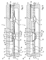
Figures 1 to 3 are cross-section views of a circuit for biological
liquid according to a first embodiment of the invention, respectively with an open valve and pipes not yet formed, with an open valve and formed pipes, and with a closed valve; -
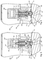
Figures 4 to 6 are cross-section views, similar to those ofFigures 1 to 3 , of the circuit according to a second embodiment of the invention; -
Figures 7 and 8 are views in perspective and in elevation of a portion of one of the shells of the circuit ofFigures 4 to 6 having an accommodation for an elastically compressible pad; -
Figure 9 is the cross-section view on IX-IX ofFigure 8 ; and -
Figures 10 to 13 are views respectively, in perspective, of a first side, in elevation, and in perspective of another side turned through 90° relative to the first side, of said elastically compressible pad. -
Figures 1 to 3 illustrate apress 10 and abag 11 which make it possible to obtain a circuit 1 for treatment of a biological liquid comprising a plurality of connectors forliquid 2 and anetwork 3 for liquid routing between thoseconnectors 2, of whichpipes 4 are visible. - The
press 10 comprises twoshells - The
shells shells -
Shell 13 has areference surface 15, which is flat here, and a plurality of shapingchannels 16 recessed intosurface 15. -
Shell 14 has aflat surface 17 on which is fastened asheet 30 having asurface 39, and shapingchannels 18 that are recessed relative to surface 39 ofsheet 30, each facing acorresponding shaping channel 16. - Generally, the
surfaces channels 18 is the mirror image of the arrangement of the shapingchannels 16. - The shaping
channels - The
surfaces channels -
Shell 14 comprises twoapertures 35, andsheet 30 comprises two fastening lugs 34 which fasten by complementarity of shape in the correspondingapertures 35 ofshell 14. - In addition to the
shells press 10 comprises, here implanted onshell 14,pinch valves 20 comprisingactuators 21 to pinch apipe 4, andsensors 22 of a physico-chemical value, for example pressure or temperature. - The
actuators 21 each comprise abody 23 fastened to theshell 14 and amoveable pinching membrane 24 having a retracted position when thevalve 20 is in an open position (seeFigures 1 and2 ), and an extended position when thevalve 20 is in a closed position (seeFigure 3 ). - The
body 23 is housed in arecess 25 ofshell 14. - In the extended position, the
moveable membrane 24 projects into one of thechannels 18. - The
valve 20 further comprises, in register with themoveable membrane 24, an elasticallycompressible pad 31, whichpad 31 forms part of thesilicone sheet 30 molded in one piece which covers the majority of thesurface 17 of theshell 14 so as to coverseveral pipes 4. - This
pad 31 has afirst face 32 nearest themoveable membrane 24 and asecond face 33 nearest the pipe to pinch 4. - The
second face 33 of the pad is concave and locally delimits the shapingchannel 18 of theshell 14. - The
common sheet 30 has two stiffeningprojections 38 close to thepad 31. - Each
sensor 22 is fastened to theshell 14 in register with achannel 18, with the distal end of thesensor 22 emerging into thatchannel 18, without actually having to touch the fluid. - Such sensors are well known and comprise for example pressure sensors which measure the pressure via the outer surface of the bag.
- At each
sensor 22, to enable the putting in place thereof, the shapingchannel 18 is not exactly the mirror image of thechannel 16. - The
bag 11 comprises twoflexible films - Here, each of the
films - The seal is a weld bead formed at the periphery of the
films - In addition to the
films connectors 2 for liquid, thebag 11 comprises a connector for apneumatic agent 5 to form thepipes 4. - The dimensions of the
bag 11 correspond to those of thesurfaces shells surface 39 of thesheet 30. - The
bag 11 is intended to be clamped by theshells bag 11 in contact with a face of the shell 13 (this face having thesurface 15 and the channels 16), and with the other face of thebag 11 being in contact with a face of the shell 30 (this face presenting surface 39). -
Figure 1 shows thebag 11 in place between theshells surfaces bag 11, but without theshells - The
bag 11 is then inflated: theconnectors 2 for liquid are obturated and a pneumatic agent is injected by theconnector 5 provided for that purpose. - The effect of the inflation of the
bag 11 is that thefilms shell 13 which presents thesurface 15 and thechannels 16, and the face of thesheet 30 which presents thesurface 39 and thechannels 18. - The
press 10 is then closed, that is to say that theshells bag 11 is clamped between theshells 13 and 14). - The
films shell 13 which presents thesurface 15 and thechannels 16 and the face of thesheet 30 which presents thesurface 39 and thechannels 18, adjacent thechannels pipes 4 of elliptical contour, as shown inFigure 2 . - The
press 10 and thebag 11 then form a circuit 1 for treating a biological liquid which is ready to be placed in service. - To simplify the drawings, the
shells Figures 1 and2 but, as indicated above, in the pre-closure position illustrated inFigure 1 , theshells - When the biological liquid to treat in the circuit formed by the
press 10 and thebag 11 has to be protected from contamination, thebag 11 is provided with obturating plugs in place on each of the connectors for liquid and on the connector for a pneumatic agent and it is sterilized, for example by gamma irradiation. The pneumatic agent injected inside thebag 11 is purified. - For example, the pneumatic agent is compressed air purified by a hydrophobic filter, such as an AERVENT® available from the company Millipore, connected to the inflating
connector 5. - The
sensors 22 have their distal end (the sensitive end) in contact with apipe 4. Eachsensor 22 makes it possible to know a physico-chemical characteristic of the liquid flowing in thepipe 4 with which its distal end is in contact, for example its temperature or its pressure. - Each
actuator 21 enables apipe 4 to be pinched between itsmoveable membrane 24 and theshell 13, to allow or prevent the passage of the liquid at that location. - To pinch the
pipe 4, thevalve 20 passes from its open position (visible inFigure 2 ) in which themoveable membrane 24 is in a retracted position in which it does not pinch thepipe 4, to its closed position (visible inFigure 3 ) in which themovable membrane 24 is in a position extended by pneumatic inflation of saidmembrane 24 in which it pinches thepipe 4. - The
membrane 24, at the time it is extended, pushes thepad 31 towards the shapingchannel 16 of theshell 13. - Thus, the
pad 31 passes from its resting configuration in which itssecond face 33 is concave and locally delimits the shapingchannel 18 of theshell 14 of thepipe 4 to pinch, to a pinching configuration in which itssecond face 33 is convex, with thefilms bag 11 at the local ity of thepipe 4 and thepad 31 being sandwiched between the shapingchannel 16 of theshell 13 of the pipe to pinch 4 and the moveablepneumatic pinching membrane 24. - By virtue of its compressibility, the
pad 31, enables possible differences in shape between theinflated membrane 24 and the shapingchannel 16 of theshell 13 to be made up. - By virtue of the elastically
compressible pad 31, the twofilms pipe 4 are thus applied sealingly against each other and the liquid can no longer flow in thepipe 4. - With the aid of
Figures 4 to 13 a second embodiment of the pinch valve will now be described. - In the same way as in the
press 10, thepress 110 comprises twoparallelepiped shells - The
shells shells Figures 1 to 3 in order to delimit anetwork 103 of cavities, each generally tubular so as then to formpipes 104 of acircuit 100. - For this,
shell 113 has areference surface 115, which is flat here, and a plurality of shapingchannels 116 recessed intosurface 115. - The
shell 114 has areference surface 117 and shapingchannels 118 recessed relative to surface 117, each facing acorresponding shaping channel 116. - Generally, the
surfaces channels 118 is the mirror image of the arrangement of the shapingchannels 116. -
Channels - In addition to the
shells press 110 comprisespinch valves 120 on theshell 114, which comprise actuators 121 for pinching apipe 104. - The
actuators 121 each comprise abody 123 fastened to theshell 114 and amoveable pinching finger 124 having a retracted position when thevalve 120 is in an open position, and an extended position when thevalve 120 is in a closed position. - The
body 123 comprises apneumatic chamber 126, apiston 127 and anaccommodation 128 provided with aspring 129 accommodated in the shell, with thespring 129 surrounding a rod linking thepiston 127 and thefinger 124. - The
pneumatic chamber 126, when it is under pressure, biases thepiston 127 against thespring 129. When thepiston 127 is at the end of its stroke, thefinger 124 is in retracted position (Figures 4 and5 ). - When the
pneumatic chamber 126 is at atmospheric pressure, thespring 129 biases thepiston 127 towards the other position of end of stroke. When the latter is reached, themoveable finger 124 is in extended position (Figure 6 ). - At its distal end, the
moveable finger 124 is shaped like the profile ofthe.shaping channel 116 of theshell 113. - In the extended position, the
moveable finger 124 projects into one of thechannels 118. - The
valve 120 further comprises, in register with themoveable finger 124, an elasticallycompressible pad 131, whichpad 131 forms part of an individual local plate 130 (shown in isolation inFigures 10 to 13 ) of silicone molded in one piece. - This
pad 131 has afirst face 132 nearest themoveable finger 124 and asecond face 133 nearest the pipe to pinch 104. - The
second face 133 of thepad 131 is concave and locally delimits the shapingchannel 118 of theshell 114. - As can be better seen in
Figures 7 to 9 , theshell 114 comprises a recessedaccommodation 160 having a curvedcentral portion 161 and two flatlateral portions 162. - The curved
central portion 161 has a cut-out 163 in the center that is adapted to allow themoveable pinching finger 124 to pass, and twoidentical apertures 164 situated at the edge of thecentral portion 161. - As better seen in
Figures 10 to 13 , thepad 131 forms an arcuate central portion of theplate 130, which comprises flatlateral walls 171 and arcuatetransverse walls 172 which surround said central portion. - Each flat
lateral wall 171 of theplate 130 is positioned on a flatlateral portion 162 of theaccommodation 160 in theshell 114, and each arcuatetransverse wall 172 is positioned on the curvedcentral portion 161 of theaccommodation 160 in theshell 114. - Thus, the
pad 131 is also positioned on the curvedcentral portion 161 of theaccommodation 160 in theshell 114. - For it to be fastened on the
shell 114, theplate 130 comprises afastening lug 173 extending from each arcuatetransverse wall 172 towards the face of theshell 114 which presents thesurface 117 and thechannels 118. - These
lugs 173 are fastened by complementarity of shape in the correspondingapertures 164 of theshell 114. - The
bag 111 comprises twoflexible films - The
bag 111 and thefilms bag 11 and thefilms Figures 1 to 3 . - Furthermore the
pipes 104 are formed in the same way as thepipes 4 ofFigures 1 to 3 . - The dimensions of the
bag 111 correspond to those of the reference surfaces 115 and 117 of theshells -
Figure 4 shows thebag 11 in place between theshells surface 117 in contact with thebag 111, but without theshells - The
bag 111 is then inflated and the effect of the inflation is that thefilms shell 113 which presents thesurface 115 and thechannels 116, and thesecond face 133 of thepad 131. - The
press 110 is then closes such that theshells bag 111. - The
films shell 113 which presents thesurface 115 and thechannels 116, and thesecond face 133 of thepad 131, adjacent thechannels pipes 104 of elliptical contour, as shown inFigure 5 . - The
press 110 and thebag 111 then form acircuit 100 for treating a biological liquid which is ready to be placed in service. - To simplify the drawings, the
shells Figures 4 and5 but, as indicated above, in the pre-closure position illustrated inFigure 4 , theshells - Each
actuator 121 enables apipe 104 to be pinched between itsmoveable finger 124 andshell 113, to allow or prevent the passage of the liquid at that location. - To pinch the
pipe 104, thevalve 120 passes from its open position (Figure 5 ) in which themoveable finger 124 is in a retracted position in which it does not pinch thepipe 104, to its closed position (Figure 6 ) in which themoveable finger 124 is in an extended position in which it pinches thepipe 104. - The
finger 124, at the time it is extended, pushes thepad 131 towards the shapingchannel 116 of theshell 113. - Thus, the
pad 131 passes from a resting configuration in which itssecond face 133 is concave and locally delimits the shapingchannel 118 of theshell 114 of thepipe 104 to pinch, to a pinching configuration in which itssecond face 133 is convex, with thepipe 104 and thepad 131 sandwiched between the shapingchannel 116 of theshell 113 of the pipe to pinch 104 and themoveable pinching finger 124. - In a variant not illustrated, the pipe to pinch has a circular contour.
- In the example illustrated in
Figures 4 to 13 , themoveable pinching member 124 of theactuator 121 has a thick edge at its end. As a variant, the moveable member of the actuator has thin edge, for example by virtue of a beveled end. - In variants not illustrated, the inflation of the bag is carried out after the clamping of the bag, or partially before and partially after the clamping of the bag.
- In a variant not illustrated, the pipes of the network for routing fluid are pre-formed, and the welding of the films is carried out before the bag is clamped between said shells.
- In a variant not illustrated, rather than being dispersed over the same shells, the sensor or sensors of a physico-chemical value and the pad are disposed on different shells; and/or no sensor is provided.
- In other variants not represented:
- instead of being in one piece, the shells are formed by a set of modular members associated with each other to delimit the different portions of the circuit, which members are provided with marks or labels to ensure that they are correctly disposed relative to each other, the marks and the labels comprising for example reference numbers or codes, and possibly being of the RFID type.
- the shells are of a material other than stainless steel, for example aluminum, plastic having in particular a high density, ceramic or wood;
- the films of the bag are of a material other than the PureFlex™ film, for example of another film with several layers compatible with biological liquids such as the film HyQ® CX5-14 available from the company Hyclone industries, or the film Platinum UltraPac available from the company Lonza;
- the single-acting pneumatic jack serving to actuate the finger such as 124 is replaced by a double-acting pneumatic jack and/or the jack is of a nature other than pneumatic, for example electrical;
- the pad is not a one-piece molding.
- It should be noted more generally that the invention is not limited to the examples described and represented.
said valve further comprising, in register with said moveable pinching member, an elastically compressible pad, which pad has a first face nearest the moveable member and a second face nearest the pipe to pinch, which pad, when the valve is in an open position, has a resting configuration in which said second face is concave and locally delimits the first shell shaping channel of the pipe to pinch, and, when the valve is in a closed position, has a pinching configuration in which said second face is convex, with said pipe and said pad sandwiched between the second shell shaping channel of the pipe to pinch and the moveable pinching member.
Claims (15)
- A circuit for biological liquid, comprising a plurality of connectors (2) and a network (3 ;103) for routing liquid between said connectors, characterized in that it comprises:- a bag (11 ;111) comprising two flexible films (45, 46 ; 145, 146) and said routing network connectors (2); and- a press (10 ; 110) comprising a first shell (14 ; 114) and a second shell (13 ; 113) clamping said bag (11 ; 111) in a state in which pipes (4 ; 104) of said liquid routing network (3 ; 103), are formed between said films (45, 46 ; 145, 146), said first shell (14 ; 114) comprising for each said pipe (4 ; 104) a shaping channel (18 ; 118), said second shell (13 ; 113) comprising for each said pipe (4 ; 104) a shaping channel (16 ; 116) facing the corresponding shaping channel (18 ; 118) of the first shell (14 ; 114); with said first shell (14 ; 114) comprising at least one pinch valve (20 ; 120) for a said pipe (4 ; 104), which valve (20 ; 120) comprises an actuator (21 ; 121) comprising a movable pinching member (24 ; 124), which valve (20 ; 120) has an open position in which the moveable member (24 ; 124) is in a retracted position in which it does not pinch the pipe (4 ; 104) and has a closed position in which the moveable member (24 ; 124) is in an extended position in which it pinches the pipe (4 ; 104);said valve (20 ; 120) further comprising, in register with said moveable pinching member (24 ; 124), an elastically compressible pad (31 ; 131), which pad (31 ; 131) has a first face (32 ; 132) nearest the moveable member (24 ; 124) and a second face (33 ; 133) nearest the pipe to pinch (4 ; 104), which pad (31 ; 131), when the valve (20 ; 120) is in an open position, has a resting configuration in which said second face (33 ; 133) is concave and locally delimits the first shell shaping channel (18 ; 118) of the pipe to pinch (4 ; 104), and, when the valve (20 ; 120) is in a closed position, has a pinching configuration in which said second face (33 ; 133) is convex, with said pipe (4 ; 104) and said pad (31 ; 131) sandwiched between the second shell shaping channel (16 ; 116) of the pipe to pinch (4 ; 104) and the moveable pinching member (24 ; 124).
- A circuit according to claim 1, characterized in that said pipe to pinch (4 ; 104) has an elliptical contour.
- A circuit according to one of claims 1 and 2, characterized in that said pad (31) forms part of a common sheet (30) covering several pipes (4).
- A circuit according to claim 3, characterized in that said common sheet (30) comprises at least one stiffening projection (38) close to the pad (31).
- A circuit according to one of claims 1 and 2, characterized in that said pad (131) forms part of an individual local plate (130).
- A circuit according to claim 5, characterized in that said pad (131) forms a central portion of said local individual plate (130), which comprises lateral (171) and transverse (172) walls which surround said central portion.
- A circuit according to any one of claims 1 to 6, characterized in that said first shell (114) comprises a recessed accommodation (160) adapted to receive said pad (131) at least partially.
- A circuit according to any one of claims 1 to 7, characterized in that said pad (31 ; 131) is fastened to said first shell (14 ; 114).
- A circuit according to claim 8, characterized in that said pad (31 ; 131) comprises fastening lugs (34, 35 ; 173) which fasten by complementarity of shape in corresponding apertures (36, 37 ; 164) of said first shell (14, 114).
- A circuit according to any one of claims 1 to 9, characterized in that said pad (31 ; 131) is formed from elastically compressible flexible plastic molded in one piece.
- A circuit according to any one of claims 1 to 10, characterized in that said pad (31 ; 131) is made of silicone.
- A circuit according to any one of claims 1 to 11, characterized in that the moveable member of the actuator (21) comprises a pneumatic membrane (24) adapted to push said pad (31) towards the second shell shaping channel (16).
- A circuit according to any one of claims 1 to 11, characterized in that the moveable member of the actuator (121) comprises a finger (124) having an end shaped like the second shell shaping channel (116).
- A circuit according to any one of claims 1 to 13, characterized in that at least one said shell (14) comprises at least one sensor (22) of a physico-chemical quantity.
- A circuit according to claim 14, characterized in that said sensor (22) and said pad (31) are disposed on said first shell (14).
Applications Claiming Priority (2)
| Application Number | Priority Date | Filing Date | Title |
|---|---|---|---|
| FR1050209A FR2955119B1 (en) | 2010-01-13 | 2010-01-13 | CIRCUIT FOR BIOLOGICAL LIQUID |
| PCT/IB2011/050089 WO2011086488A1 (en) | 2010-01-13 | 2011-01-10 | Circuit for biological liquid |
Publications (2)
| Publication Number | Publication Date |
|---|---|
| EP2523756A1 EP2523756A1 (en) | 2012-11-21 |
| EP2523756B1 true EP2523756B1 (en) | 2013-11-27 |
Family
ID=42735424
Family Applications (1)
| Application Number | Title | Priority Date | Filing Date |
|---|---|---|---|
| EP20110703032 Active EP2523756B1 (en) | 2010-01-13 | 2011-01-10 | Circuit for biological liquid |
Country Status (10)
| Country | Link |
|---|---|
| US (2) | US9051929B2 (en) |
| EP (1) | EP2523756B1 (en) |
| JP (1) | JP5606554B2 (en) |
| CN (1) | CN102753270B (en) |
| BR (1) | BR112012017273B1 (en) |
| ES (1) | ES2443190T3 (en) |
| FR (1) | FR2955119B1 (en) |
| IN (1) | IN2012DN06325A (en) |
| SG (1) | SG182380A1 (en) |
| WO (1) | WO2011086488A1 (en) |
Families Citing this family (20)
| Publication number | Priority date | Publication date | Assignee | Title |
|---|---|---|---|---|
| FR2931838B1 (en) | 2008-06-02 | 2010-06-11 | Millipore Corp | INSTALLATION FOR TREATING A BIOLOGICAL LIQUID. |
| FR2940145B1 (en) * | 2008-12-24 | 2011-03-25 | Millipore Corp | TROLLEY AND INSTALLATION FOR TREATING A BIOLOGICAL LIQUID |
| FR2941385B1 (en) | 2009-01-23 | 2011-04-01 | Millipore Corp | METHOD FOR PROVIDING A CIRCUIT FOR BIOLOGICAL LIQUID AND CIRCUIT OBTAINED |
| FR2955119B1 (en) | 2010-01-13 | 2012-12-28 | Millipore Corp | CIRCUIT FOR BIOLOGICAL LIQUID |
| FR2960794B1 (en) | 2010-06-08 | 2012-07-27 | Millipore Corp | DEVICE FOR A PLANT FOR TREATING BIOLOGICAL LIQUID |
| FR2960795B1 (en) | 2010-06-08 | 2012-07-27 | Millipore Corp | DEVICE FOR A PLANT FOR TREATING BIOLOGICAL LIQUID |
| FR2960796B1 (en) | 2010-06-08 | 2014-01-24 | Millipore Corp | DEVICE FOR A PLANT FOR TREATING BIOLOGICAL LIQUID |
| FR2961713B1 (en) | 2010-06-23 | 2012-08-10 | Millipore Corp | POCKET FOR CIRCUIT OF A BIOLOGICAL LIQUID TREATMENT FACILITY |
| FR2961711B1 (en) | 2010-06-23 | 2012-08-17 | Millipore Corp | POCKET FOR CIRCUIT OF A BIOLOGICAL LIQUID TREATMENT FACILITY |
| FR2963573B1 (en) | 2010-08-03 | 2012-08-31 | Millipore Corp | PUMPING TROLLEY FOR A BIOLOGICAL LIQUID TREATMENT FACILITY |
| FR2973396B1 (en) | 2011-03-28 | 2013-05-10 | Millipore Corp | FACILITY FOR TREATING BIOLOGICAL LIQUID |
| WO2012143693A1 (en) | 2011-04-18 | 2012-10-26 | Martin John Hofmann | Apparatus and methods for fluid processing and flow control |
| FR2993572B1 (en) * | 2012-07-23 | 2016-04-15 | Emd Millipore Corp | CIRCUIT FOR BIOLOGICAL LIQUID COMPRISING A PINCH VALVE |
| FR2993473B1 (en) * | 2012-07-23 | 2014-08-29 | Emd Millipore Corp | DEVICE FOR A PLANT FOR TREATING BIOLOGICAL LIQUID |
| JP2015021458A (en) * | 2013-07-22 | 2015-02-02 | Nkワークス株式会社 | Infusion pump |
| US9746391B2 (en) | 2013-10-30 | 2017-08-29 | Alphinity, Llc | Fluid monitoring device with disposable inner liner with sensor integration |
| CN106233119B (en) | 2014-01-17 | 2019-07-26 | 艾尔菲能堤有限责任公司 | Fluid inspection component with sensor function |
| BR112016027815B1 (en) * | 2014-05-27 | 2022-07-12 | Illumina, Inc. | SYSTEMS AND METHODS FOR BIOCHEMICAL ANALYSIS INCLUDING A BASE INSTRUMENT AND REMOVABLE CARTRIDGE |
| US10406252B2 (en) | 2017-01-19 | 2019-09-10 | Curium Us Llc | Systems and methods for autoclave cart loading and unloading system |
| US11639717B2 (en) * | 2019-04-09 | 2023-05-02 | Miltenyi Biotec B.V. & Co. KG | Perestaltic pump and device for isolating cells from biological tissue |
Family Cites Families (120)
| Publication number | Priority date | Publication date | Assignee | Title |
|---|---|---|---|---|
| US2413853A (en) | 1942-03-18 | 1947-01-07 | Metalwash Machinery Co | Article washing machine |
| US2787403A (en) | 1953-09-01 | 1957-04-02 | Fmc Corp | Pumping apparatus |
| US2941575A (en) | 1955-09-14 | 1960-06-21 | Paul R Malmberg | Apparatus for dielectric fabrication |
| US3022229A (en) | 1957-04-01 | 1962-02-20 | Getinge Mek Verkst S Aktiebola | Cultivation plant |
| US3179117A (en) | 1964-03-02 | 1965-04-20 | Cart Cleaning Corp Of America | Trailer mounted cleaner |
| US3667487A (en) | 1970-12-11 | 1972-06-06 | Richardson Chem Cleaning Servi | Integrated chemical cleaning apparatus |
| US3774762A (en) | 1971-01-20 | 1973-11-27 | E Lichtenstein | Analogue fluid flow programming structures |
| US4370983A (en) | 1971-01-20 | 1983-02-01 | Lichtenstein Eric Stefan | Computer-control medical care system |
| US3772154A (en) | 1971-05-03 | 1973-11-13 | Technicon Instr | Method and apparatus for automated antibiotic susceptibility analysis of bacteria samples |
| GB1434786A (en) | 1973-04-02 | 1976-05-05 | Lichtenstein E S | Apparatus including disposable array for processing body fluids |
| FR2241615A1 (en) | 1973-08-22 | 1975-03-21 | Aseta | Tilting fermentation and homogenisation tank - for e.g. making improved wines, and allowing easy evacuation of marc |
| US4113623A (en) | 1977-04-25 | 1978-09-12 | Food Automation-Service Techniques, Inc. | Filter apparatus |
| US4332750A (en) | 1980-03-11 | 1982-06-01 | Essex Chemical Corporation | Blow-molding and degating hollow shapes |
| IL69333A (en) | 1983-07-26 | 1986-04-29 | Biolog Ind | Process for plant tissue culture propagation |
| US5141866A (en) | 1983-07-26 | 1992-08-25 | Robert Levin | Process for plant tissue culture propagation |
| JPS6281543A (en) | 1985-10-07 | 1987-04-15 | Kyowa Seimitsu Kk | Apparatus for automatic pretreatment of specimen supplied to sampler in chromatograph apparatus |
| US4915119A (en) | 1986-04-21 | 1990-04-10 | Dober Chemical Corporation | Cleaning apparatus and method |
| US4784751A (en) | 1986-09-24 | 1988-11-15 | Keller Machine Works | Method and apparatus for reclaiming contaminated oil |
| US4790118A (en) | 1987-04-13 | 1988-12-13 | Econodose, Inc. | Medication packaging and dispensing system |
| JPS63319011A (en) | 1987-06-19 | 1988-12-27 | Takano:Kk | Parallel filtration circuit |
| US4852851A (en) | 1987-12-11 | 1989-08-01 | Integrated Fluidics, Inc. | Valve with flexible sheet member |
| JPH04348743A (en) | 1990-10-02 | 1992-12-03 | Daiichi Kogyo Kk | Automatic deaerating device for blood collecting tube |
| FR2673853B1 (en) | 1991-03-12 | 1993-07-16 | Leflond Odile | UNDERWATER ROTATING MIXER REACTOR, PARTICULARLY FOR THE ANAEROBIC FERMENTATION OF HUMIDIFIED HOUSEHOLD GARBAGE. |
| IT1251639B (en) | 1991-10-28 | 1995-05-17 | Sviluppo Settori Impiego Srl | PROCEDURE FOR THE PRODUCTION OF MANUFACTURES STARTING FROM REINFORCED THERMOPLASTIC SHEETS |
| US5290518A (en) | 1992-08-17 | 1994-03-01 | Eastman Kodak Company | Flexible extraction device with burstable sidewall |
| US5265912A (en) | 1992-10-19 | 1993-11-30 | Natividad Jeffrey A | Toy train apparatus |
| US5520885A (en) | 1993-01-19 | 1996-05-28 | Thermogenesis Corporation | Fibrinogen processing apparatus, method and container |
| DE69413166T2 (en) | 1993-03-03 | 1999-05-12 | Deka Products Lp | DEVICE FOR PERITONAL DIALYSIS WITH A LIQUID DISTRIBUTION AND PUMP CASSETTE EQUIPPED FOR AIR SEPARATION. |
| US5678568A (en) | 1993-07-27 | 1997-10-21 | Olympus Optical Co., Ltd. | System control apparatus, medical system control apparatus and image-plane display method of medical system control apparatus |
| WO1996012952A1 (en) | 1994-10-20 | 1996-05-02 | Eai Corporation | Air transportable, modular analytical laboratory |
| US5985653A (en) | 1995-06-07 | 1999-11-16 | Aastrom Biosciences, Inc. | Incubator apparatus for use in a system for maintaining and growing biological cells |
| JP2832586B2 (en) | 1995-08-04 | 1998-12-09 | 株式会社トミー精工 | DNA extraction and purification method |
| FR2747780B1 (en) | 1996-04-22 | 1998-06-05 | Cogema | DEVICE FOR TAKING HARMFUL LIQUID SAMPLES, ESPECIALLY LOADED WITH SOLID PARTICLES |
| US5738645A (en) | 1996-04-30 | 1998-04-14 | Medtronic, Inc. | Soft tip blood reservoir for heart-lung machines |
| US6808675B1 (en) | 1996-06-25 | 2004-10-26 | Thermogenesis Corp. | Freezing and thawing bag, mold, apparatus and method |
| US6146124A (en) | 1996-06-25 | 2000-11-14 | Thermogenesis Corp. | Freezing and thawing bag, mold, apparatus and method |
| US6213334B1 (en) | 1996-09-05 | 2001-04-10 | Baxter International Inc | Flexible, three-dimensional containers and methods for making them |
| US6073942A (en) | 1996-11-14 | 2000-06-13 | Windquest Companies, Inc. | Movable dual cart assembly |
| US6129099A (en) | 1997-09-17 | 2000-10-10 | Foster; James B. | Pallet washing apparatus and method |
| US6361642B1 (en) | 1997-12-02 | 2002-03-26 | Baxter International Inc. | Heat and pressure-formed flexible containers |
| JPH11169432A (en) | 1997-12-09 | 1999-06-29 | Hosokawa Yoko:Kk | Infusion bag and its production |
| DE1075328T1 (en) | 1998-05-01 | 2001-10-11 | Ammann Kelly G | AUTOMATIC DIAGNOSTIC ANALYSIS DEVICE AND METHOD |
| US6099734A (en) | 1998-07-08 | 2000-08-08 | Baxter International Inc. | Apparatus, membranes and methods for removing organic compounds from a biological fluid |
| US6228255B1 (en) | 1998-07-24 | 2001-05-08 | Dialysis Systems, Inc. | Portable water treatment facility |
| US20040222341A1 (en) | 1999-01-27 | 2004-11-11 | Health Science Technology, LLC | Intravenous equipment hangers |
| IL144421A (en) | 1999-02-22 | 2004-12-15 | Henry Kopf | Purification of biological substances |
| FR2795476B1 (en) | 1999-06-22 | 2001-07-27 | Biomerieux Sa | VALVE FOR DIRECTING A FLUID IN AN ANALYSIS CARD |
| EP1087010B1 (en) | 1999-09-08 | 2011-11-09 | Levitronix LLC | Bioreactor with single-use pump |
| US6303025B1 (en) | 2000-02-17 | 2001-10-16 | Jon E. Houchens | Water purification system with baffled flow |
| BR0102376A (en) * | 2000-06-16 | 2002-02-19 | Xerox Corp | Clamping tube mechanism |
| WO2002014462A1 (en) * | 2000-08-14 | 2002-02-21 | The Regents Of The University Of California | Biosensors and methods for their use |
| US8505959B2 (en) | 2000-09-18 | 2013-08-13 | Valiant Rock, Llc | Cart transportable mobile medical critical care point of need field installation units |
| EP1258260A3 (en) | 2000-10-04 | 2003-11-26 | Terumo Kabushiki Kaisha | Peritoneal dialysis apparatus |
| EP1239277A1 (en) | 2001-03-09 | 2002-09-11 | Infineon Technologies AG | Measurement arrangement |
| US6982063B2 (en) | 2001-05-25 | 2006-01-03 | Matrix Technologies Corp | Automated pipetting system |
| US6673595B2 (en) | 2001-08-27 | 2004-01-06 | Biocrystal, Ltd | Automated cell management system for growth and manipulation of cultured cells |
| US20030175947A1 (en) * | 2001-11-05 | 2003-09-18 | Liu Robin Hui | Enhanced mixing in microfluidic devices |
| MXPA04009532A (en) * | 2002-04-01 | 2005-01-25 | Emerson Electric Co | Pinch valve with pressure containing member. |
| US20040031507A1 (en) | 2002-05-09 | 2004-02-19 | Advanced Blending Corp. | Systems and method for automated cart washing |
| US7153286B2 (en) | 2002-05-24 | 2006-12-26 | Baxter International Inc. | Automated dialysis system |
| DE10224750A1 (en) | 2002-06-04 | 2003-12-24 | Fresenius Medical Care De Gmbh | Device for the treatment of a medical fluid |
| EP1511575B1 (en) | 2002-06-13 | 2009-01-14 | Graco Minnesota Inc. | Adjustable flow texture sprayer with peristaltic pump |
| US9283521B2 (en) | 2002-06-14 | 2016-03-15 | Parker-Hannifin Corporation | Single-use manifold and sensors for automated, aseptic transfer of solutions in bioprocessing applications |
| US7238164B2 (en) * | 2002-07-19 | 2007-07-03 | Baxter International Inc. | Systems, methods and apparatuses for pumping cassette-based therapies |
| FR2844052B1 (en) * | 2002-08-28 | 2005-07-01 | Commissariat Energie Atomique | DEVICE FOR MEASURING THE ELECTRIC ACTIVITY OF BIOLOGICAL ELEMENTS AND ITS APPLICATIONS |
| US7073765B2 (en) | 2002-11-13 | 2006-07-11 | Hill-Rom Services, Inc. | Apparatus for carrying medical equipment |
| US20040104153A1 (en) | 2002-11-29 | 2004-06-03 | Chung-Hsiang Yang | Portable water purifier |
| US20040259240A1 (en) | 2003-06-17 | 2004-12-23 | Fadden Stephen J. | Method and apparatus for filtration of bioreactor recombinant proteins |
| EP1508791A1 (en) | 2003-08-22 | 2005-02-23 | Ismatec SA, Laboratoriumstechnik | Device for automated bioreactor sampling |
| US8038639B2 (en) | 2004-11-04 | 2011-10-18 | Baxter International Inc. | Medical fluid system with flexible sheeting disposable unit |
| US7198052B2 (en) | 2004-03-12 | 2007-04-03 | General Electric Company | Mobile flushing unit and process |
| WO2005090403A2 (en) | 2004-03-12 | 2005-09-29 | Biovest International, Inc. | Method and apparatus for antibody purification |
| WO2005095089A1 (en) | 2004-03-30 | 2005-10-13 | Showa Denko Plastic Products Co., Ltd. | Method and apparatus for producing bag with mouth member |
| US7326355B2 (en) | 2004-03-31 | 2008-02-05 | Hyclone Laboratories, Inc. | Mobile filtration facility and methods of use |
| US20060024212A1 (en) | 2004-08-02 | 2006-02-02 | Hwang David S | Analytical equipment cart |
| KR100618320B1 (en) * | 2004-09-14 | 2006-08-31 | 삼성전자주식회사 | An apparatus for making a fluid flow, and a disposable chip having the same |
| JP4831436B2 (en) | 2004-10-21 | 2011-12-07 | ジーイー・ヘルスケア・バイオサイエンス・アクチボラグ | Chromatographic ligand |
| US7935074B2 (en) | 2005-02-28 | 2011-05-03 | Fresenius Medical Care Holdings, Inc. | Cassette system for peritoneal dialysis machine |
| KR20080072006A (en) | 2005-11-01 | 2008-08-05 | 가부시키가이샤 메디넷 | Shaker for cell culture and shaken culture system in cell culture method |
| JP5101819B2 (en) * | 2006-01-16 | 2012-12-19 | 株式会社カネカ | Cell culture equipment |
| US20100317102A1 (en) * | 2006-01-17 | 2010-12-16 | Tsutomu Suzuki | Cell Culture Method and Automatic Culture System Using the Method |
| WO2007094254A1 (en) | 2006-02-15 | 2007-08-23 | Aida Engineering, Ltd. | Microchannel chip and method for manufacturing such chip |
| CA2567559A1 (en) | 2006-02-28 | 2007-08-28 | Ian M. Moorey | Portable water purification system |
| US7485224B2 (en) | 2006-03-03 | 2009-02-03 | Sam Houston State University | Mobile bioremediation systems |
| DE102006018824A1 (en) | 2006-04-22 | 2007-10-25 | Bayer Technology Services Gmbh | Disposable bioreactor |
| DK2029722T3 (en) | 2006-05-22 | 2020-01-02 | Biovest Int Inc | METHOD AND CELL PRODUCTION PROCEDURE |
| JP4721227B2 (en) | 2006-05-22 | 2011-07-13 | アイダエンジニアリング株式会社 | Microchannel chip and manufacturing method thereof |
| US8545636B2 (en) | 2006-07-27 | 2013-10-01 | Atmel Corporation | Conductivity control of water content in solvent strip baths |
| US20080116122A1 (en) | 2006-11-22 | 2008-05-22 | Genitope Corporation | Chromatography systems comprising single-use components |
| CA2671750C (en) * | 2006-12-14 | 2015-04-07 | Boehringer Ingelheim Microparts Gmbh | Device for the intake or manipulation of a liquid |
| DE102006059459B4 (en) * | 2006-12-14 | 2009-06-18 | Boehringer Ingelheim Microparts Gmbh | Device for receiving or manipulating a liquid and method for producing such a device |
| JP4957260B2 (en) | 2007-01-16 | 2012-06-20 | 横河電機株式会社 | Chemical reaction cartridge and method of use thereof |
| GB0706240D0 (en) * | 2007-03-30 | 2007-05-09 | Concept 2 Manufacture Design O | A valve means for gas control devices |
| CN101765448A (en) | 2007-08-02 | 2010-06-30 | 米利波尔公司 | System and apparatus for processing fluid samples |
| US7798456B2 (en) | 2007-08-21 | 2010-09-21 | Hill-Rom Services, Inc. | Transferable patient care equipment support |
| US8105487B2 (en) | 2007-09-25 | 2012-01-31 | Fresenius Medical Care Holdings, Inc. | Manifolds for use in conducting dialysis |
| US8292857B2 (en) | 2007-10-04 | 2012-10-23 | Dornoch Medical Systems, Inc. | Medical waste fluid collection and disposal system |
| WO2009046989A2 (en) | 2007-10-11 | 2009-04-16 | Roche Diagnostics Gmbh | Carrier for an infusion system |
| US8114276B2 (en) | 2007-10-24 | 2012-02-14 | Baxter International Inc. | Personal hemodialysis system |
| US9415150B2 (en) | 2007-11-09 | 2016-08-16 | Baxter Healthcare S.A. | Balanced flow dialysis machine |
| CA3057806C (en) | 2007-11-29 | 2021-11-23 | Fresenius Medical Care Holdings, Inc. | System and method for conducting hemodialysis and hemofiltration |
| US8075468B2 (en) | 2008-02-27 | 2011-12-13 | Fenwal, Inc. | Systems and methods for mid-processing calculation of blood composition |
| FR2931838B1 (en) | 2008-06-02 | 2010-06-11 | Millipore Corp | INSTALLATION FOR TREATING A BIOLOGICAL LIQUID. |
| US7892496B2 (en) * | 2008-06-20 | 2011-02-22 | Silverbrook Research Pty Ltd | Mechanically-actuated microfluidic pinch valve |
| JP5762954B2 (en) | 2008-06-25 | 2015-08-12 | ジーイー・ヘルスケア・バイオサイエンス・バイオプロセス・コーポレイション | Automatic installation of disposable flow paths |
| FR2940145B1 (en) | 2008-12-24 | 2011-03-25 | Millipore Corp | TROLLEY AND INSTALLATION FOR TREATING A BIOLOGICAL LIQUID |
| DE102009005874A1 (en) | 2009-01-21 | 2010-07-22 | Thinxxs Microtechnology Ag | Valve, in particular for a component of microfluid technology |
| FR2941385B1 (en) * | 2009-01-23 | 2011-04-01 | Millipore Corp | METHOD FOR PROVIDING A CIRCUIT FOR BIOLOGICAL LIQUID AND CIRCUIT OBTAINED |
| CA2750473A1 (en) | 2009-02-06 | 2010-08-12 | Velomedix, Inc. | Method and apparatus for inducing therapeutic hypothermia |
| DE102009009728A1 (en) * | 2009-02-19 | 2010-09-02 | Thinxxs Microtechnology Ag | Flow cell with integrated fluid storage |
| FR2943134B1 (en) | 2009-03-13 | 2011-10-07 | Millipore Corp | DEVICE FOR DETERMINING A PHYSICAL SIZE OF A LIQUID CIRCULATING IN A CONDUIT |
| FR2955119B1 (en) | 2010-01-13 | 2012-12-28 | Millipore Corp | CIRCUIT FOR BIOLOGICAL LIQUID |
| CA2833001C (en) | 2010-04-21 | 2020-06-23 | Yves Larcher | Automated cell culture system |
| FR2960794B1 (en) | 2010-06-08 | 2012-07-27 | Millipore Corp | DEVICE FOR A PLANT FOR TREATING BIOLOGICAL LIQUID |
| FR2960796B1 (en) | 2010-06-08 | 2014-01-24 | Millipore Corp | DEVICE FOR A PLANT FOR TREATING BIOLOGICAL LIQUID |
| FR2960795B1 (en) | 2010-06-08 | 2012-07-27 | Millipore Corp | DEVICE FOR A PLANT FOR TREATING BIOLOGICAL LIQUID |
| FR2961713B1 (en) | 2010-06-23 | 2012-08-10 | Millipore Corp | POCKET FOR CIRCUIT OF A BIOLOGICAL LIQUID TREATMENT FACILITY |
| FR2961711B1 (en) | 2010-06-23 | 2012-08-17 | Millipore Corp | POCKET FOR CIRCUIT OF A BIOLOGICAL LIQUID TREATMENT FACILITY |
| FR2963573B1 (en) | 2010-08-03 | 2012-08-31 | Millipore Corp | PUMPING TROLLEY FOR A BIOLOGICAL LIQUID TREATMENT FACILITY |
| FR2973396B1 (en) | 2011-03-28 | 2013-05-10 | Millipore Corp | FACILITY FOR TREATING BIOLOGICAL LIQUID |
-
2010
- 2010-01-13 FR FR1050209A patent/FR2955119B1/en not_active Expired - Fee Related
-
2011
- 2011-01-10 CN CN201180009086.9A patent/CN102753270B/en active Active
- 2011-01-10 IN IN6325DEN2012 patent/IN2012DN06325A/en unknown
- 2011-01-10 WO PCT/IB2011/050089 patent/WO2011086488A1/en active Application Filing
- 2011-01-10 SG SG2012049813A patent/SG182380A1/en unknown
- 2011-01-10 EP EP20110703032 patent/EP2523756B1/en active Active
- 2011-01-10 JP JP2012548506A patent/JP5606554B2/en active Active
- 2011-01-10 ES ES11703032T patent/ES2443190T3/en active Active
- 2011-01-10 BR BR112012017273A patent/BR112012017273B1/en active IP Right Grant
- 2011-01-11 US US13/004,425 patent/US9051929B2/en active Active
-
2013
- 2013-11-15 US US14/080,826 patent/US9181941B2/en active Active
Also Published As
| Publication number | Publication date |
|---|---|
| US20120018018A1 (en) | 2012-01-26 |
| BR112012017273A2 (en) | 2016-04-19 |
| US9181941B2 (en) | 2015-11-10 |
| SG182380A1 (en) | 2012-08-30 |
| FR2955119A1 (en) | 2011-07-15 |
| ES2443190T3 (en) | 2014-02-18 |
| EP2523756A1 (en) | 2012-11-21 |
| FR2955119B1 (en) | 2012-12-28 |
| BR112012017273B1 (en) | 2019-12-10 |
| US20140069537A1 (en) | 2014-03-13 |
| JP2013516974A (en) | 2013-05-16 |
| US9051929B2 (en) | 2015-06-09 |
| JP5606554B2 (en) | 2014-10-15 |
| WO2011086488A1 (en) | 2011-07-21 |
| CN102753270B (en) | 2014-09-24 |
| IN2012DN06325A (en) | 2015-10-02 |
| CN102753270A (en) | 2012-10-24 |
Similar Documents
| Publication | Publication Date | Title |
|---|---|---|
| EP2523756B1 (en) | Circuit for biological liquid | |
| EP2874748B1 (en) | Circuit for biological liquid comprising a pinch valve | |
| US10195605B2 (en) | Method for providing a circuit for biological liquid and circuit obtained | |
| CN101109452A (en) | Vacuum valve | |
| EP2890421B1 (en) | Spring-open sheeting for fluid processing cassette | |
| EP2107243A3 (en) | Dual-cavity fluid conveying apparatus | |
| KR20160113636A (en) | Improved sealant liquid container and kit comprising such a container |
Legal Events
| Date | Code | Title | Description |
|---|---|---|---|
| PUAI | Public reference made under article 153(3) epc to a published international application that has entered the european phase |
Free format text: ORIGINAL CODE: 0009012 |
|
| 17P | Request for examination filed |
Effective date: 20120807 |
|
| AK | Designated contracting states |
Kind code of ref document: A1 Designated state(s): AL AT BE BG CH CY CZ DE DK EE ES FI FR GB GR HR HU IE IS IT LI LT LU LV MC MK MT NL NO PL PT RO RS SE SI SK SM TR |
|
| DAX | Request for extension of the european patent (deleted) | ||
| GRAP | Despatch of communication of intention to grant a patent |
Free format text: ORIGINAL CODE: EPIDOSNIGR1 |
|
| INTG | Intention to grant announced |
Effective date: 20130709 |
|
| GRAS | Grant fee paid |
Free format text: ORIGINAL CODE: EPIDOSNIGR3 |
|
| GRAA | (expected) grant |
Free format text: ORIGINAL CODE: 0009210 |
|
| AK | Designated contracting states |
Kind code of ref document: B1 Designated state(s): AL AT BE BG CH CY CZ DE DK EE ES FI FR GB GR HR HU IE IS IT LI LT LU LV MC MK MT NL NO PL PT RO RS SE SI SK SM TR |
|
| REG | Reference to a national code |
Ref country code: GB Ref legal event code: FG4D |
|
| REG | Reference to a national code |
Ref country code: CH Ref legal event code: EP |
|
| REG | Reference to a national code |
Ref country code: AT Ref legal event code: REF Ref document number: 642454 Country of ref document: AT Kind code of ref document: T Effective date: 20131215 |
|
| REG | Reference to a national code |
Ref country code: IE Ref legal event code: FG4D |
|
| REG | Reference to a national code |
Ref country code: CH Ref legal event code: NV Representative=s name: KIRKER AND CIE S.A., CH |
|
| REG | Reference to a national code |
Ref country code: DE Ref legal event code: R096 Ref document number: 602011003963 Country of ref document: DE Effective date: 20140123 |
|
| REG | Reference to a national code |
Ref country code: ES Ref legal event code: FG2A Ref document number: 2443190 Country of ref document: ES Kind code of ref document: T3 Effective date: 20140218 |
|
| REG | Reference to a national code |
Ref country code: NL Ref legal event code: T3 |
|
| REG | Reference to a national code |
Ref country code: AT Ref legal event code: MK05 Ref document number: 642454 Country of ref document: AT Kind code of ref document: T Effective date: 20131127 |
|
| REG | Reference to a national code |
Ref country code: LT Ref legal event code: MG4D |
|
| PG25 | Lapsed in a contracting state [announced via postgrant information from national office to epo] |
Ref country code: SE Free format text: LAPSE BECAUSE OF FAILURE TO SUBMIT A TRANSLATION OF THE DESCRIPTION OR TO PAY THE FEE WITHIN THE PRESCRIBED TIME-LIMIT Effective date: 20131127 Ref country code: HR Free format text: LAPSE BECAUSE OF FAILURE TO SUBMIT A TRANSLATION OF THE DESCRIPTION OR TO PAY THE FEE WITHIN THE PRESCRIBED TIME-LIMIT Effective date: 20131127 Ref country code: LT Free format text: LAPSE BECAUSE OF FAILURE TO SUBMIT A TRANSLATION OF THE DESCRIPTION OR TO PAY THE FEE WITHIN THE PRESCRIBED TIME-LIMIT Effective date: 20131127 Ref country code: FI Free format text: LAPSE BECAUSE OF FAILURE TO SUBMIT A TRANSLATION OF THE DESCRIPTION OR TO PAY THE FEE WITHIN THE PRESCRIBED TIME-LIMIT Effective date: 20131127 Ref country code: NO Free format text: LAPSE BECAUSE OF FAILURE TO SUBMIT A TRANSLATION OF THE DESCRIPTION OR TO PAY THE FEE WITHIN THE PRESCRIBED TIME-LIMIT Effective date: 20140227 Ref country code: IS Free format text: LAPSE BECAUSE OF FAILURE TO SUBMIT A TRANSLATION OF THE DESCRIPTION OR TO PAY THE FEE WITHIN THE PRESCRIBED TIME-LIMIT Effective date: 20140327 |
|
| PG25 | Lapsed in a contracting state [announced via postgrant information from national office to epo] |
Ref country code: LV Free format text: LAPSE BECAUSE OF FAILURE TO SUBMIT A TRANSLATION OF THE DESCRIPTION OR TO PAY THE FEE WITHIN THE PRESCRIBED TIME-LIMIT Effective date: 20131127 Ref country code: AT Free format text: LAPSE BECAUSE OF FAILURE TO SUBMIT A TRANSLATION OF THE DESCRIPTION OR TO PAY THE FEE WITHIN THE PRESCRIBED TIME-LIMIT Effective date: 20131127 Ref country code: RS Free format text: LAPSE BECAUSE OF FAILURE TO SUBMIT A TRANSLATION OF THE DESCRIPTION OR TO PAY THE FEE WITHIN THE PRESCRIBED TIME-LIMIT Effective date: 20131127 Ref country code: CY Free format text: LAPSE BECAUSE OF FAILURE TO SUBMIT A TRANSLATION OF THE DESCRIPTION OR TO PAY THE FEE WITHIN THE PRESCRIBED TIME-LIMIT Effective date: 20131127 |
|
| PG25 | Lapsed in a contracting state [announced via postgrant information from national office to epo] |
Ref country code: PT Free format text: LAPSE BECAUSE OF FAILURE TO SUBMIT A TRANSLATION OF THE DESCRIPTION OR TO PAY THE FEE WITHIN THE PRESCRIBED TIME-LIMIT Effective date: 20140327 |
|
| PG25 | Lapsed in a contracting state [announced via postgrant information from national office to epo] |
Ref country code: EE Free format text: LAPSE BECAUSE OF FAILURE TO SUBMIT A TRANSLATION OF THE DESCRIPTION OR TO PAY THE FEE WITHIN THE PRESCRIBED TIME-LIMIT Effective date: 20131127 |
|
| REG | Reference to a national code |
Ref country code: DE Ref legal event code: R097 Ref document number: 602011003963 Country of ref document: DE |
|
| PG25 | Lapsed in a contracting state [announced via postgrant information from national office to epo] |
Ref country code: SK Free format text: LAPSE BECAUSE OF FAILURE TO SUBMIT A TRANSLATION OF THE DESCRIPTION OR TO PAY THE FEE WITHIN THE PRESCRIBED TIME-LIMIT Effective date: 20131127 Ref country code: PL Free format text: LAPSE BECAUSE OF FAILURE TO SUBMIT A TRANSLATION OF THE DESCRIPTION OR TO PAY THE FEE WITHIN THE PRESCRIBED TIME-LIMIT Effective date: 20131127 Ref country code: RO Free format text: LAPSE BECAUSE OF FAILURE TO SUBMIT A TRANSLATION OF THE DESCRIPTION OR TO PAY THE FEE WITHIN THE PRESCRIBED TIME-LIMIT Effective date: 20131127 Ref country code: CZ Free format text: LAPSE BECAUSE OF FAILURE TO SUBMIT A TRANSLATION OF THE DESCRIPTION OR TO PAY THE FEE WITHIN THE PRESCRIBED TIME-LIMIT Effective date: 20131127 Ref country code: LU Free format text: LAPSE BECAUSE OF FAILURE TO SUBMIT A TRANSLATION OF THE DESCRIPTION OR TO PAY THE FEE WITHIN THE PRESCRIBED TIME-LIMIT Effective date: 20140110 |
|
| PG25 | Lapsed in a contracting state [announced via postgrant information from national office to epo] |
Ref country code: DK Free format text: LAPSE BECAUSE OF FAILURE TO SUBMIT A TRANSLATION OF THE DESCRIPTION OR TO PAY THE FEE WITHIN THE PRESCRIBED TIME-LIMIT Effective date: 20131127 |
|
| PLBE | No opposition filed within time limit |
Free format text: ORIGINAL CODE: 0009261 |
|
| STAA | Information on the status of an ep patent application or granted ep patent |
Free format text: STATUS: NO OPPOSITION FILED WITHIN TIME LIMIT |
|
| 26N | No opposition filed |
Effective date: 20140828 |
|
| REG | Reference to a national code |
Ref country code: IE Ref legal event code: MM4A |
|
| REG | Reference to a national code |
Ref country code: DE Ref legal event code: R097 Ref document number: 602011003963 Country of ref document: DE Effective date: 20140828 |
|
| PG25 | Lapsed in a contracting state [announced via postgrant information from national office to epo] |
Ref country code: IE Free format text: LAPSE BECAUSE OF NON-PAYMENT OF DUE FEES Effective date: 20140110 |
|
| PG25 | Lapsed in a contracting state [announced via postgrant information from national office to epo] |
Ref country code: SI Free format text: LAPSE BECAUSE OF FAILURE TO SUBMIT A TRANSLATION OF THE DESCRIPTION OR TO PAY THE FEE WITHIN THE PRESCRIBED TIME-LIMIT Effective date: 20131127 |
|
| PG25 | Lapsed in a contracting state [announced via postgrant information from national office to epo] |
Ref country code: MC Free format text: LAPSE BECAUSE OF FAILURE TO SUBMIT A TRANSLATION OF THE DESCRIPTION OR TO PAY THE FEE WITHIN THE PRESCRIBED TIME-LIMIT Effective date: 20131127 |
|
| REG | Reference to a national code |
Ref country code: FR Ref legal event code: PLFP Year of fee payment: 6 |
|
| PG25 | Lapsed in a contracting state [announced via postgrant information from national office to epo] |
Ref country code: MT Free format text: LAPSE BECAUSE OF FAILURE TO SUBMIT A TRANSLATION OF THE DESCRIPTION OR TO PAY THE FEE WITHIN THE PRESCRIBED TIME-LIMIT Effective date: 20131127 |
|
| PG25 | Lapsed in a contracting state [announced via postgrant information from national office to epo] |
Ref country code: SM Free format text: LAPSE BECAUSE OF FAILURE TO SUBMIT A TRANSLATION OF THE DESCRIPTION OR TO PAY THE FEE WITHIN THE PRESCRIBED TIME-LIMIT Effective date: 20131127 |
|
| PG25 | Lapsed in a contracting state [announced via postgrant information from national office to epo] |
Ref country code: BG Free format text: LAPSE BECAUSE OF FAILURE TO SUBMIT A TRANSLATION OF THE DESCRIPTION OR TO PAY THE FEE WITHIN THE PRESCRIBED TIME-LIMIT Effective date: 20131127 Ref country code: GR Free format text: LAPSE BECAUSE OF FAILURE TO SUBMIT A TRANSLATION OF THE DESCRIPTION OR TO PAY THE FEE WITHIN THE PRESCRIBED TIME-LIMIT Effective date: 20140228 |
|
| PG25 | Lapsed in a contracting state [announced via postgrant information from national office to epo] |
Ref country code: HU Free format text: LAPSE BECAUSE OF FAILURE TO SUBMIT A TRANSLATION OF THE DESCRIPTION OR TO PAY THE FEE WITHIN THE PRESCRIBED TIME-LIMIT; INVALID AB INITIO Effective date: 20110110 Ref country code: TR Free format text: LAPSE BECAUSE OF FAILURE TO SUBMIT A TRANSLATION OF THE DESCRIPTION OR TO PAY THE FEE WITHIN THE PRESCRIBED TIME-LIMIT Effective date: 20131127 |
|
| REG | Reference to a national code |
Ref country code: FR Ref legal event code: PLFP Year of fee payment: 7 |
|
| REG | Reference to a national code |
Ref country code: FR Ref legal event code: PLFP Year of fee payment: 8 |
|
| PG25 | Lapsed in a contracting state [announced via postgrant information from national office to epo] |
Ref country code: MK Free format text: LAPSE BECAUSE OF FAILURE TO SUBMIT A TRANSLATION OF THE DESCRIPTION OR TO PAY THE FEE WITHIN THE PRESCRIBED TIME-LIMIT Effective date: 20131127 |
|
| PG25 | Lapsed in a contracting state [announced via postgrant information from national office to epo] |
Ref country code: AL Free format text: LAPSE BECAUSE OF FAILURE TO SUBMIT A TRANSLATION OF THE DESCRIPTION OR TO PAY THE FEE WITHIN THE PRESCRIBED TIME-LIMIT Effective date: 20131127 |
|
| PGFP | Annual fee paid to national office [announced via postgrant information from national office to epo] |
Ref country code: BE Payment date: 20221216 Year of fee payment: 13 |
|
| PGFP | Annual fee paid to national office [announced via postgrant information from national office to epo] |
Ref country code: ES Payment date: 20230209 Year of fee payment: 13 Ref country code: CH Payment date: 20230106 Year of fee payment: 13 |
|
| PGFP | Annual fee paid to national office [announced via postgrant information from national office to epo] |
Ref country code: IT Payment date: 20221213 Year of fee payment: 13 Ref country code: DE Payment date: 20221207 Year of fee payment: 13 |
|
| P01 | Opt-out of the competence of the unified patent court (upc) registered |
Effective date: 20230602 |
|
| PGFP | Annual fee paid to national office [announced via postgrant information from national office to epo] |
Ref country code: GB Payment date: 20231207 Year of fee payment: 14 |
|
| PGFP | Annual fee paid to national office [announced via postgrant information from national office to epo] |
Ref country code: NL Payment date: 20231215 Year of fee payment: 14 Ref country code: FR Payment date: 20231212 Year of fee payment: 14 |
|
| PGFP | Annual fee paid to national office [announced via postgrant information from national office to epo] |
Ref country code: BE Payment date: 20231219 Year of fee payment: 14 |
|
| PGFP | Annual fee paid to national office [announced via postgrant information from national office to epo] |
Ref country code: ES Payment date: 20240202 Year of fee payment: 14 |